Embed Size (px)
Citation preview
Welding Engineering Program
WE Graduate Seminar, Autumn 1999
The Ultrasonic Weld MechanismState of the technology
Edgar de VriesKarl Graff
Welding Engineering Program
UIA 2002, New York, NY
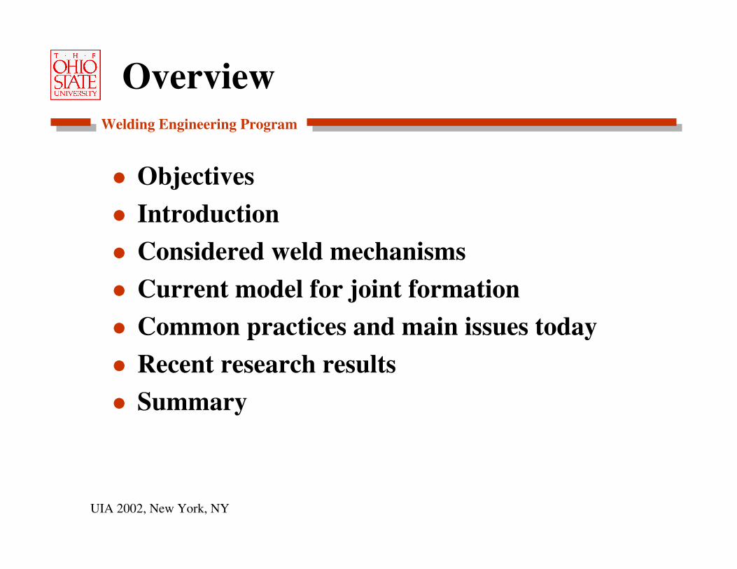
Overview
Objectives
Introduction
Considered weld mechanisms
Current model for joint formation
Common practices and main issues today
Recent research results
Summary
Welding Engineering Program
UIA 2002, New York, NY
Objectives
Collect and summarize the available literature on Ultrasonic Metal Welding (USMW).
Review key developments over 50+ years.
Identify the most recent theories on the mechanism of USMW.
Identify areas where further research is needed.
Welding Engineering Program
UIA 2002, New York, NY
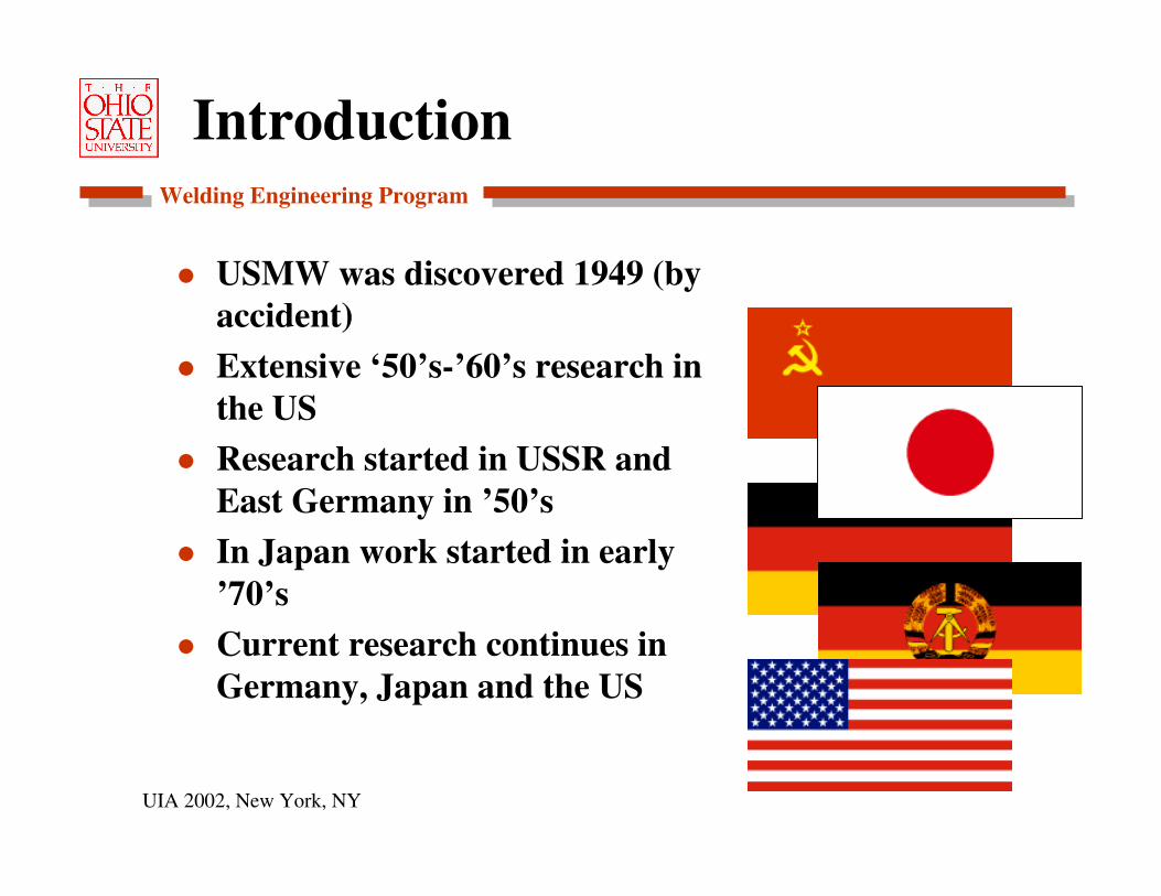
Introduction
USMW was discovered 1949 (by accident)Extensive ‘50’s-’60’s research in the USResearch started in USSR and East Germany in ’50’sIn Japan work started in early ’70’sCurrent research continues in Germany, Japan and the US
Welding Engineering Program
UIA 2002, New York, NY
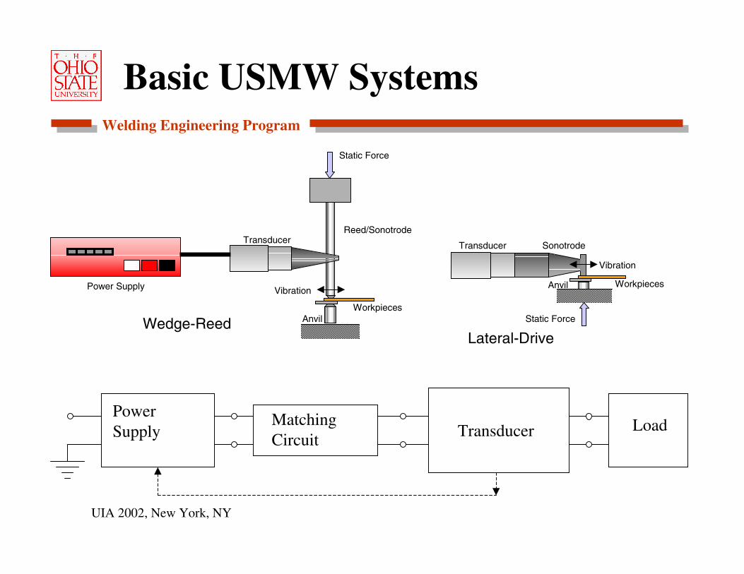
Basic USMW Systems
Static Force
SonotrodeTransducer
Anvil Workpieces
Vibration
Static Force
Reed/SonotrodeTransducer
AnvilWorkpieces
VibrationPower Supply
Wedge-Reed
PowerSupply
Matching Circuit Transducer Load
Lateral-Drive
Welding Engineering Program
UIA 2002, New York, NY
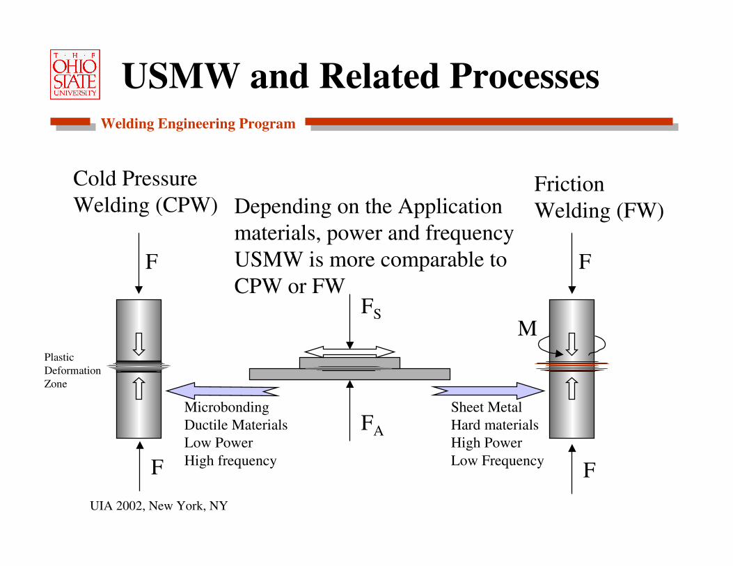
USMW and Related Processes
FS
FA
M
F
FF
F
Cold PressureWelding (CPW)
FrictionWelding (FW)Depending on the Application
materials, power and frequencyUSMW is more comparable toCPW or FW
MicrobondingDuctile MaterialsLow PowerHigh frequency
Sheet MetalHard materialsHigh PowerLow Frequency
Plastic DeformationZone
Welding Engineering Program
UIA 2002, New York, NY
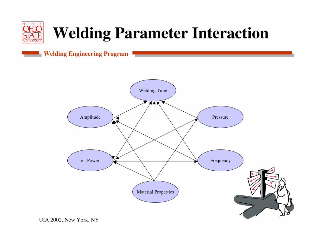
Welding Parameter Interaction
Welding Time
Material Properties
Frequency
Amplitude
el. Power
Pressure
Welding Engineering Program
UIA 2002, New York, NY
Bonding Mechanisms
Fusion-Melting has been considered possible at the interface. Interface microstructure has been associated with melting and rapid solidification. But USMW now considered a solid state process.
Recrystallization- Observed in ultrasonically welded joints but a gross reorientation of grains or the microstructure is generally not possible.
Welding Engineering Program
UIA 2002, New York, NY
Bonding Mechanisms (cont’d)
Diffusion- Has been observed, especially along gain boundaries, but generally bulk diffusion does not take place.
Plastic deformation with metallic adhesion-Observed in all USMW interfaces. The material mixing and subsequent metallic adhesion is considered the most important bonding mechanism. All other processes are possible, but are not necessary.

Welding Engineering Program
UIA 2002, New York, NY
Evolution of the Weld
Normal load presses the surface asperities into contactSlip deforms the asperities and adjusts the surfacesSublayer deformation causes Oxides to dissipate and intense material mixing
a. Contacting Surfaces due to Normal Load
b. Bonded Area due to interface Slip
c. Fully Grown Bonded Area by Sublayer Plastic Deformation
Broken Surface Films
CavitiesUnbonded Surface
FS
FS
FS
Welding Engineering Program
UIA 2002, New York, NY
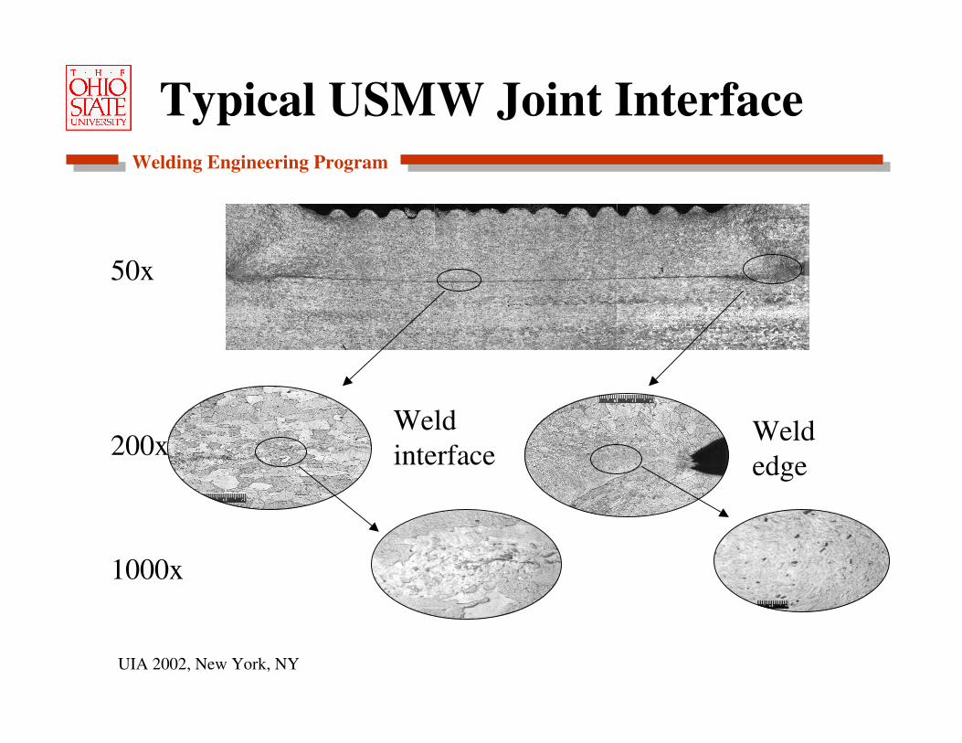
Typical USMW Joint Interface
Weld interface
Weld edge
50x
200x
1000x
Welding Engineering Program
UIA 2002, New York, NY
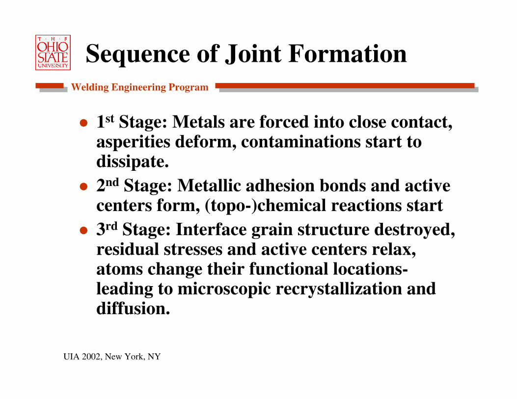
Sequence of Joint Formation
1st Stage: Metals are forced into close contact, asperities deform, contaminations start to dissipate.2nd Stage: Metallic adhesion bonds and active centers form, (topo-)chemical reactions start3rd Stage: Interface grain structure destroyed, residual stresses and active centers relax, atoms change their functional locations-leading to microscopic recrystallization and diffusion.

Welding Engineering Program
UIA 2002, New York, NY
Model (cont’d)
The three stages take place simultaneously or within a very short time difference.The last stage is responsible for the formation of a strong joint, because exchange effects occur between the metallic substances. This stage relies on elevated temperatures.If metals are welded that have no solubility, the joint strength relies only on inter atomic interaction.
Welding Engineering Program
UIA 2002, New York, NY
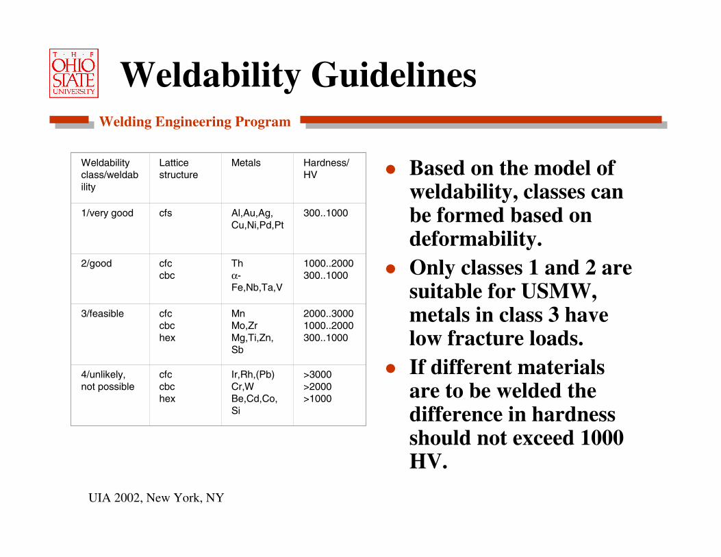
Weldability Guidelines
Based on the model of weldability, classes can be formed based on deformability.Only classes 1 and 2 are suitable for USMW, metals in class 3 have low fracture loads.If different materials are to be welded the difference in hardness should not exceed 1000 HV.
Weldabilityclass/weldability
Lattice structure
Metals Hardness/ HV
1/very good cfs Al,Au,Ag,Cu,Ni,Pd,Pt
300..1000
2/good cfccbc
Thα-Fe,Nb,Ta,V
1000..2000300..1000
3/feasible cfccbchex
MnMo,ZrMg,Ti,Zn,Sb
2000..30001000..2000300..1000
4/unlikely, not possible
cfccbchex
Ir,Rh,(Pb)Cr,WBe,Cd,Co,Si
>3000>2000>1000

Welding Engineering Program
UIA 2002, New York, NY
Common Practices and Issues
Lateral Drive system with rigid anvil, amplitude controlled sonotrode and energy controlled weld process – widely used.If aluminum sheet metal is welded, good weld strength often is accompanied by “tip sticking.”Welding parameters change as surface conditions change. However control systems do not account for changing conditions-leading to a variable process.
Welding Engineering Program
UIA 2002, New York, NY
Recent Experiments-Background
USMW process still not fully understood.
The Wedge Reed design has provided strong joint strength with low sonotrode sticking.
Correlate the sequence of events (initial, welding, extrusion stage) to vibration conditions.
If surface conditions are not well controlled, weld process is also unreliable.
Welding Engineering Program
UIA 2002, New York, NY
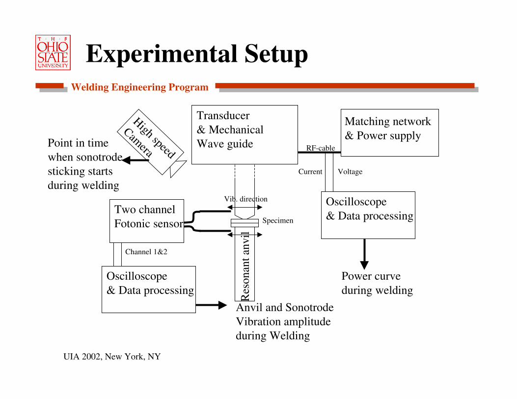
Experimental Setup
Oscilloscope& Data processing
Matching network& Power supply
Transducer & Mechanical Wave guide
Specimen
Vib. direction
VoltageCurrent
Power curve during welding
Two channelFotonic sensor
Oscilloscope& Data processing
Channel 1&2
Anvil and SonotrodeVibration amplitudeduring Welding
High speed
CameraPoint in timewhen sonotrode sticking startsduring welding
RF-cable
Res
onan
t anv
il
Welding Engineering Program
UIA 2002, New York, NY
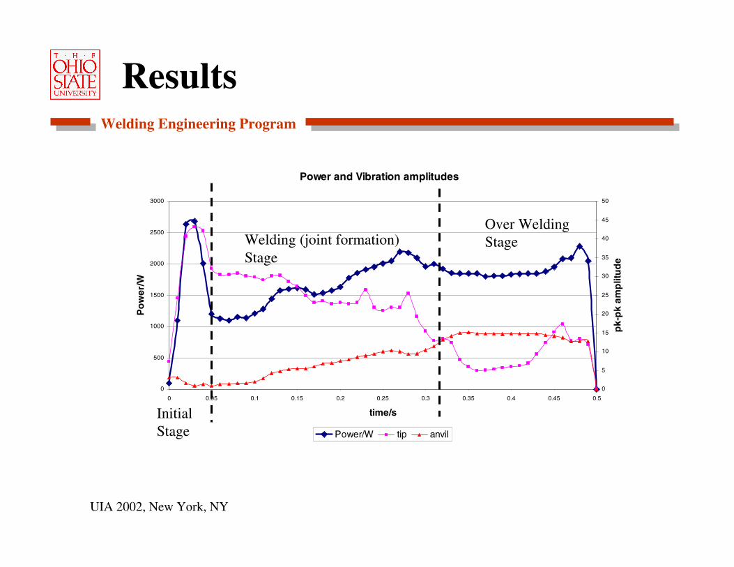
Results
Power and Vibration amplitudes
0
500
1000
1500
2000
2500
3000
0 0.05 0.1 0.15 0.2 0.25 0.3 0.35 0.4 0.45 0.5
time/s
Po
wer
/W
0
5
10
15
20
25
30
35
40
45
50
pk-
pk
amp
litu
de
Power/W tip anvil
Initial Stage
Welding (joint formation)Stage
Over Welding Stage

Welding Engineering Program
UIA 2002, New York, NY
Summary
Research on USMW has been conducted for 50+ years.USMW is commonly used for electrical connections, tube and package sealing and wire bonding.Models for basic parameter interactions and weld mechanism have been developed.For aluminum sheet metal welding, large scale applications remain a challenge.