Embed Size (px)
Citation preview

The Ultimate Solution:
Eliminate Iron Bacteria in the Well
www.berrysystemsinc.com

Mission Statement
Water is the most precious molecule on the planet. In the 21st century, with water supplies shrinking, water will replace oil as the premiere natural resource. Clean water is essential to a high standard of living. Poor water quality negatively impacts every aspect of life. Precious groundwater resources must be managed and protected by implementing strategies to ensure groundwater quantity, such as well yields, and groundwater quality with respect to bacteriological impacts. At Berry Systems, we believe everyone deserves clean water. We bring innovative products to market and aggressively service that market with integrity by collaborating with our employees, vendors, customers, and water industry specialists who share our goal of making water the pristine resource it was designed to be.
926 Carolina Drive Lugoff, SC 29078
Phone: (803) 408-6730 Fax: (803) 408-6784
www.berrysystemsinc.com
GWP-20, GWP-25, GWP-40, GWP-25LB, GWP-40LB
Rev. 02 09/18/2008
BioShield GWP
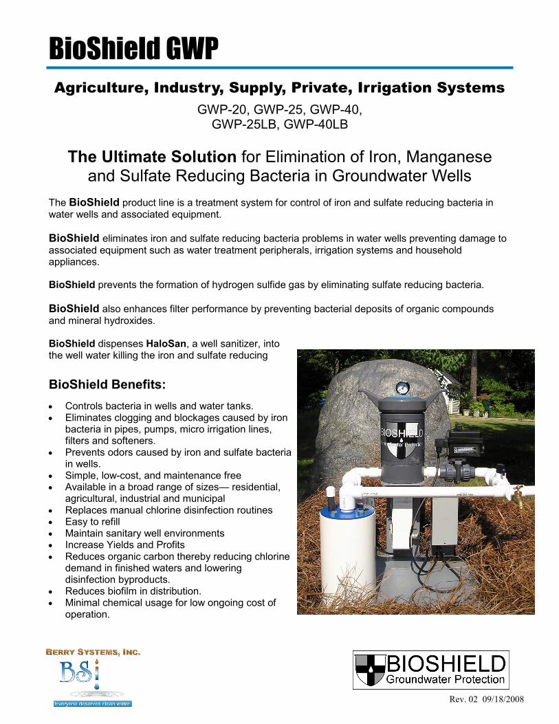
The BioShield product line is a treatment system for control of iron and sulfate reducing bacteria in water wells and associated equipment.
BioShield eliminates iron and sulfate reducing bacteria problems in water wells preventing damage to associated equipment such as water treatment peripherals, irrigation systems and household appliances. BioShield prevents the formation of hydrogen sulfide gas by eliminating sulfate reducing bacteria.
BioShield also enhances filter performance by preventing bacterial deposits of organic compounds and mineral hydroxides. BioShield dispenses HaloSan, a well sanitizer, into the well water killing the iron and sulfate reducing
The Ultimate Solution for Elimination of Iron, Manganese and Sulfate Reducing Bacteria in Groundwater Wells
Agriculture, Industry, Supply, Private, Irrigation Systems
BioShield Benefits:
Controls bacteria in wells and water tanks. Eliminates clogging and blockages caused by iron
bacteria in pipes, pumps, micro irrigation lines, filters and softeners.
Prevents odors caused by iron and sulfate bacteria in wells.
Simple, low-cost, and maintenance free Available in a broad range of sizes— residential,
agricultural, industrial and municipal Replaces manual chlorine disinfection routines Easy to refill Maintain sanitary well environments Increase Yields and Profits Reduces organic carbon thereby reducing chlorine
demand in finished waters and lowering disinfection byproducts.
Reduces biofilm in distribution. Minimal chemical usage for low ongoing cost of
operation.
Rev. 02 09/18/2008
BioShield GWP
The Ultimate Solution for Elimination of Iron, Manganese and Sulfate Reducing Bacteria in Groundwater Wells
The BioShield GWP product line is industrial grade. Designed for a broad spectrum of applications ranging from residential installations to agriculture and water supply wells, the installation package consists of an industrial grade erosion feeder, 1‖ or 1-1/2‖ electrically operated true union ball valve, a Class 2 UL Listed 24 volt power supply, and a digital timer with excellent programming flexibility. The valve operator, power supply and timer are encased in NEMA 4 housings. PLC controlled systems are available for unique applications. Contact Berry Systems, Inc. for further details.
BioShield Treatment Method BioShield dispenses HaloSan, a well sanitizer, into the well water killing iron and sulfate reducing bacteria. Sessile organisms residing within biofilm possess a number of advantages over their free-swimming or planktonic counterparts, including increased resistance to adverse environmental conditions such as shocking and antibacterial agents. Biofilm development causes significant problems in the areas of public health, medicine, and industry. Accordingly, there has been a great deal of research to better understand biofilm development and to identify improved strategies for biofouling control. Recent work in this area has focused on the role of cell-to-cell signaling within biofilm populations. It is now believed that many different types of bacteria are able to produce and respond to various hormone-like signal molecules. A particular subset of these molecules have been shown to be involved in biofilm formation and dispersal. HaloSan works by triggering the dispersion mechanism in biofilm bacteria. Once the bacteria are dispersed into the bulk fluid, they are easily eliminated by the sanitizer.
Environmental Impact of Biofouling Precious groundwater resources must be managed and protected by implementing strategies to ensure groundwater quantity, such as well yields, and groundwater quality with respect to bacteriological impacts. The number one reason for loss of production and abandonment of groundwater wells is biofouling, and the primary agent of biofouling is iron bacteria. Improper well abandonment and drilling of additional wells to avoid iron bacteria is not the solution; furthermore, it adds to the problem by creating environments for additional bacterial contamination. The solution is to maintain the well biologically by controlling the bacteria in an ongoing method. BioShield treats the well once per 12 to 24 hours with a minimum of chemical intervention 1 to 3 ppm in the well proper. For new wells we recommend the installation of a BioShield Dispenser to maintain a sanitary well environment to protect the well from the effects of biofouling. For existing wells which have become biofouled, we recommend rehabilitation of the well with NSF certified products designed for this purpose followed by the installation of a BioShield Dispenser to prevent the inevitable recurrence of biofouling. For your clients with submersible pumps who have experienced a loss of flow and pressure due to iron bacteria but cannot afford well rehabilitation, the installation of the BioShield Dispenser will restore the well by dispersing and removing the buildup in the well, pump and distribution lines over a period of one to three weeks. Protect your clients’ groundwater assets: recommend the BioShield Dispenser to keep the water flowing and free of nuisance, opportunistic and pathogenic bacteria.
BioShield GWP
Rev. 02 09/18/2008
Agriculture, Industry, Supply, Private, Irrigation Systems
BioShield is the ultimate solution for eliminating clogging, blockages and slime in pipes, pumps and micro irrigation lines. BioShield prevents clogging, odor, and chemical resistant staining caused by iron and sulfate bacteria in wells. Well water is contaminated by a variety of naturally occurring bacteria which utilize the minerals in the water. BioShield eliminates the bacteria and the biofouling they cause. Elimination of these biofouling bacteria in the well is unique to the BioShield product line. This revolutionary approach distinguishes the BioShield product line from many products which treat the water after it has exited the well. Get pristine water from your well.
Agriculture For agriculture, no product keeps the water flowing like the BioShield Dispenser. Poultry and livestock will not consume adequate quantities of water for efficient feed conversion if that water is unpleasant. Deliver pristine water for maximum consumption and feed conversion for increased yields and profits for your agricultural clients.
Irrigation For overhead and micro-irrigation clients, keep the water flowing with a BioShield Dispenser. Plant foliage will respond favorably as cleaner water prevents the blue sheen and dark spots which are caused by overhead irrigation with biofouled water. Micro-irrigation components will not clog, resulting in more efficient irrigation. For clients who are irrigating landscape plantings, the BioShield Dispenser will prevent bacterial chemical resistant staining of surfaces such as walkways and decorative lighting and fencing. Because the chemical intervention is minimal, so is the ongoing cost of treatment. Whether they are located on golf courses or the common and commercial areas of residential subdivisions, the people enjoying these beautifully landscaped areas will not detect any unpleasant odor as the irrigation system is working.
Industry Industrial monitoring wells can hardly serve the purpose for which they were designed and installed if they are biofouled. Maintain this asset with the addition of an appropriately sized BioShield Dispenser.
Supply For municipalities, which are looking at doubling their cost of treatment as they abandon their groundwater assets for surface water, the BioShield Dispenser can provide a revenue return like no product on the market. Additional benefits include reduction of organic carbon thereby reducing chlorine demand in finished waters and lowering disinfection byproducts. The BioShield Dispenser also reduces biofilm in the distribution system. Agriculture, industry, or municipal applications – anything water touches can benefit from the installation of a BioShield Dispenser.

Rev. 03 08/09/2010
BioShield Specifications
BioShield Selection Guidelines 1. Pump gpm 2. Water Supply Line Size 3. Water Depth 4. Well Casing Diameter
GWP Model 20 25 40 25LB 40LB
Max Flow Rate (gpm) 40 40 60 40 60
Inlet/Outlet (B) 1‖ 1‖ 1½‖ 1‖ 1½‖
HaloSan Load (lbs.) 1.1 2.2 2.2 6.6 6.6
Height (A) 12.375 12.375 12.875 22.375 22.875
Use the BioShield Selection Program (at www.berrysystemsinc.com/brochure.html) to choose the correct model, calculate the system run time, and project annual HaloSan usage.
BioShield GWP
The Ultimate Solution for Elimination of Iron, Manganese and Sulfate Reducing Bacteria in Groundwater Wells
Flow rate refers to pumping gpm not recharge gpm. Maximum operating pressure 150 psi. Contact Berry Systems, Inc. for installation options for wells with high flow rates (100 - 1,000gpm). *Agency fees applicable for municipal installation requiring NSF Certification. *Large Erosion feeders are custom made for specific applications.

Caution: Restrict the flow through the isolation valve by partially closing it should you notice a significant pressure drop through the system during operation.
See Wiring Diagram for wiring instructions.
BioShield Installation Diagram
Rev. 04 09/18/2008
BioShield GWP Basic Installation Instruction Berry Systems, Inc. recommends that all installations are made by a professional licensed
contractor. Be certain to follow all applicable local, county and state Codes for your site. Dispenser must be installed above water return point for proper drainage. For constant pressure systems Berry Systems, Inc. recommends the installation of an
appropriately sized dole valve on the treatment arm of the system to achieve a constant rate of flow into the erosion feeder.
At the well cut the main water supply line and install a ―T‖ to create a loop back to the well. Follow the ―T‖ with an isolation valve. The isolation valve is closed for operator safety when the dispenser is serviced.
Install a union fitting on the line to facilitate any well maintenance. After the union fitting, an electrically operated ball valve is installed. The BioShield dispenser is installed with flow arrow aligned in the correct direction. Install a second union fitting. Return water into the well. Installation of 24 volt power supply and timer may be remote or at well head. We recommend the installation of a spigot at the well head for water sampling purposes. The entire system must be protected from freezing temperatures. Use supplied bracket to mount canister to protect piping from torque when removing canister cover. BioShield should not be exposed to a head of water or continuous flow while not in use.
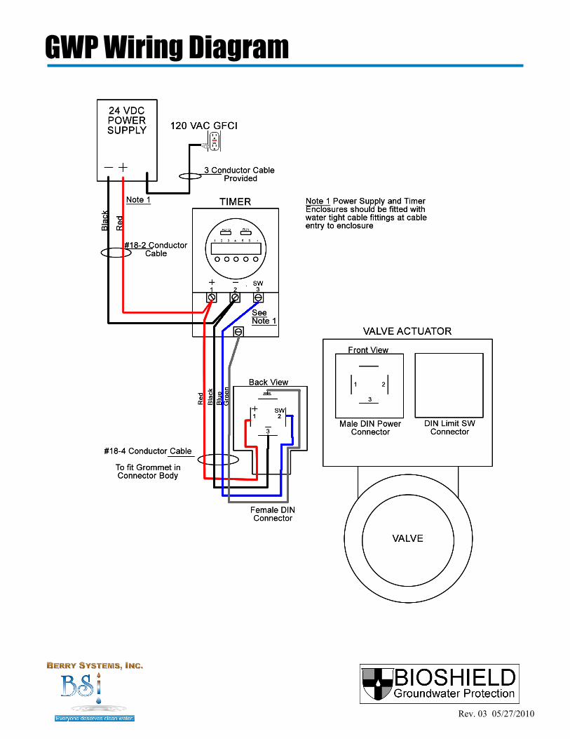
GWP Wiring Diagram
Rev. 03 05/27/2010

Technical Specifications DESCRIPTION
90° Electric actuator in plastic housing with manual override by outgoing shaft With unipolar wiring (integrated relay) for On /Off For torques of 177 Lb-in
STANDARD EQUIPMENT Voltage 24 VDC 4 Adjustable limit switches 5 Amp Electric connections: Two DIN 43650 3P+T Connectors Manual override Torque limiter Mechanical limit stops 90° + 5°
TECHNICAL DATA Duty cycle rating at maximum torque = 30% of operating time (CE134) Working temperature: +14°F to +131°F (-10°C to +55°C)
Enclosure: NEMA 4 and IP 65
Model Torque Voltages Power Travel Time
EK20.X03S 177 lb-in/20 Nm 24 VDC 11 W 7/10 s
Handle for Manual Override
ABS Cover
Clutch Knob
Nylon GF6.6 Housing
EK20.X03S
Rev. 01 09/18/2008
Electric Actuator

CRP Series PVC Ball Valves Installation, Repair & Maintenance
INSTALLATION: 1. Turn the valve to the closed position. 2. The preferred flow direction is with the "Adjust" end as the inlet. 3. Install assembled valve body in line, being cautious not to dislodge face O-Ring seals. 4. Hand tighten union nuts. 5. Union connections for 1/2" to 2" plastic valves should be hand tight. For valves over 2", a strap wrench, may be used to
tighten the nut 1/4 to 1/2 turn past hand tight. Caution: Do not over tighten. NORMAL MAINTENANCE: 1. External Seat Wear Adjustment Feature: In the event that a leak occurs from seat wear, there is no need to remove the
valve cartridge from the system. Before adjusting, be sure that the system is depressurized. Operate the valve to the closed position, and then tighten the union nut on the side featuring the word "Adjust". Tighten to 1/4 turn maximum. This will increase the load of the ball carrier to compensate for seat wear.
DISASSEMBLY: 1. Do not disassemble under pressure. 2. First position the valve open, and then remove the union nuts. 3. Pull out the locking strip on the "Adjust" side of the valve. 4. Close the valve and then push out the carrier by pressing on the ball from the opposite side. 5. With the carrier removed, you have access to the valve seats. The stem can also be-removed at this time, after removing the manual handle or actuator assembly. 6. A complete set of repair parts is available. ASSEMBLY: 1. Inspect the body and ball for wear and damage. Replace if necessary. 2. Roll stem seal O-Rings into grooves on stem and insert into valve body. 3. Install Teflon seal in solid end of valve body. Bevel side of seal must face ball. 4. Install valve ball. 5. Install handle (if used and rotate to open). 6. Roll carrier O-Ring seal into groove on carrier. 7. Install Teflon seal in carrier with bevel side of seal facing ball. 8. Install carrier into valve body. Install locking strip with clockwise motion until rectangular end snaps into place. 9. Install face O-Rings in the valve body and carrier grooves.
Electric Actuator
Wiring Information for DIN Electrical Connectors Wiring the electrical connector: 1. Remove the connector screw first and then use a flat screwdriver to pry apart the two connector halves. Note that the
screw placed in the connector locks the two halves together. 2. The center terminal is an optional ground and the two power wires can each be connected to either of the side
terminals. Wire according to wiring diagram. 3. Replace the connector on the actuator and hold in place with the screw.
4. There are two different types of connectors that you may be using, 1/2" NPTF Conduit and Lead Wire. If you are using
the Lead Wire type, a jacketed multi-conductor wire is recommended. A rubber grommet is compressed around the jacketed conductor to make a seal. If a tight seal is not important, then any type of wiring can be used.
1” Ball Valve and Electric Operator
1” NPT Ball Valve Features: PVC body and ball Three piece true union body Full port Teflon seats EPDM O-rings Required mounting bracket in molded plastic
Electric Operator Features: On/Off operation, unipoler wiring (integrated relay) Torque 177 Lb/in. 24 VDC Sealed plastic NEMA 4 housing 90° Electric Actuator UL Listed Manual override by Outgoing Shaft 11 Watts 7/10 Second operation Electric Connections: (2) DIN43650 3P+T Connectors
Rev. 01 09/18/2008

Electric Actuator Installation and Use
Electric Actuator Installation and Use CAUTION! This actuator is factory tested. The limit switches have been set for 90 degree use, there is no need to open the cover. Shut off the power supply before: Removing the cover Disconnecting the gear Using the lever Consult the technical sheet before mounting or maintaining/repairing the actuator. Be careful before installation that the travel of the manual override is free of any obstacle. This actuator is NEMA 4 rated and is maintenance free.
Manual Override In case of power failure, it is possible to operate manually. To operate the manual override, turn the clutch knob from AUTO to MAN and hold. The shaft is now free. Turn the handle on the top of the actuator to the open position. To return the handle to the closed position, hold the knob in the manual position and return the handle to closed. The motor will return to AUTO mode by turning the clutch knob to the AUTO position. CAUTION: do not force the clutch knob, this button is not manual override.
EK20 Electric Actuator DIN Connectors
Open Position
Closed Position
Electric Actuator Parts List 1. Visual Position Indicator/Handle 2. Shaft 3. Stainless Steel Screws 4. 3P+T DIN43650 Base 5. 3P+T DIN43650 Connectors 6. Screws 7. ABS Cover 8. Screws 9. Clutch Knob 10. Nylon GF6.6 Housing
Return Manual Position
Return Auto Position
Rev. 01 09/18/2008

24 VDC Class 2 Power Supply
Input Voltage 120 / 240 / 277 Volts AC, 1 AMP Max.
Output Voltage 24.0 ±0.3 Volts DC
Output Current 1.7A, 40W/4A, 96W
Current Limit 4.5 ±0.25 Amps
Load Regulation 0.1 Tol Volts
Line Regulation 0.1 Tol Volts
Input Frequency 50-60 Hertz
Efficiency 70% Typical
MTBF 100,000 Hours
Operating Temp. -30 to 60° Celsius
Storage Temp -65 to 90° Celsius
Humidity 100% Non Cond
Size 8.56‖ x 4.25‖ x 3.25‖
Shipping Weight 7.0 Pounds
Single Circuit 24VDC Power Supply Specifications
Auto overload protection Indoor/Outdoor NEMA 3R Rain tight Wet Location Enclosure Input cord attached UL Listed Approvals - UL1310 Listed. Class 2 Power Supplies, UL1310, UL48 Recognized Sign Accessories. Construction - NEMA 3R Rain Tight Enclosure Wall Mounting - Class 1 Conduit Access Wiring Compartment 1 Year Limited Warranty
Rev. 01 09/18/2008
BioShield GWP Digital Timer
Rev. 02 09/18/2008
Digital Time Clock Setting Instructions
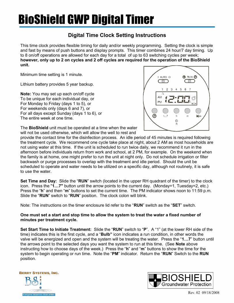
This time clock provides flexible timing for daily and/or weekly programming. Setting the clock is simple and fast by means of push buttons and display prompts. This timer combines 24 hour/7 day timing. Up to 8 on/off operations are allowed for each day for a total of up to 63 switching cycles per week; however, only up to 2 on cycles and 2 off cycles are required for the operation of the BioShield unit. Minimum time setting is 1 minute. Lithium battery provides 5 year backup. Note: You may set up each on/off cycle To be unique for each individual day, or For Monday to Friday (days 1 to 5), or For weekends only (days 6 and 7), or For all days except Sunday (days 1 to 6), or The entire week at one time. The BioShield unit must be operated at a time when the water will not be used otherwise, which will allow the well to rest and provide the contact time for the disinfection process. An idle period of 45 minutes is required following the treatment cycle. We recommend one cycle take place at night, about 2 AM as most households are not using water at this time. If the unit is scheduled to run twice daily, we recommend it run in the afternoon before individuals return from work and school, at 2 PM, for example. On the weekend when the family is at home, one might prefer to run the unit at night only. Do not schedule irrigation or filter backwash or purge processes to overlap with the treatment and idle period. Should the unit be scheduled to operate and water needs to be utilized on a specific day, although not routinely, it is safe to use the water. Set Time and Day: Slide the ―RUN‖ switch (located in the upper RH quadrant of the timer) to the clock icon. Press the "1…7" button until the arrow points to the current day. (Monday=1, Tuesday=2, etc.) Press the ―h‖ and then ―m‖ buttons to set the current time. The PM indicator shows noon to 11:59 p.m. Slide the ―RUN‖ switch to ―RUN‖ position. The clock colon will blink. Note: The instructions on the timer enclosure lid refer to the ―RUN‖ switch as the ―SET‖ switch. One must set a start and stop time to allow the system to treat the water a fixed number of minutes per treatment cycle. Set Start Time to Initiate Treatment: Slide the ―RUN‖ switch to ―P‖. A ―1‖ (at the lower RH side of the time) indicates this is the first cycle, and a ―Bulb” icon indicates a run condition, in other words the valve will be energized and open and the system will be treating the water. Press the ―1…7‖ button until the arrows point to the selected days you want the system to run at this time. (See Note above instructing how to choose days of the week.) Press the ―h‖ and ―m‖ buttons to show the time for the system to begin operating or run time. Note the ―PM‖ indicator. Return the ―RUN‖ Switch to the RUN position.
BioShield GWP Digital Timer
Rev. 02 08/09/2010
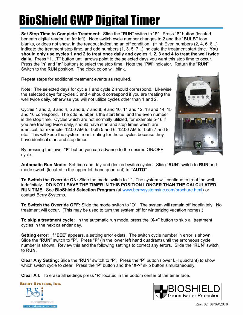
Set Stop Time to Complete Treatment: Slide the ―RUN‖ switch to ―P‖. Press ―P‖ button (located beneath digital readout at far left). Note switch cycle number changes to 2 and the ―BULB” icon blanks, or does not show, in the readout indicating an off condition. (Hint: Even numbers (2, 4, 6, 8...) indicate the treatment stop time, and odd numbers (1, 3, 5, 7...) indicate the treatment start time. You should only use cycles 1 and 2 to treat once daily and cycles 1, 2, 3 and 4 to treat the well twice daily. Press “1…7” button until arrows point to the selected days you want this stop time to occur. Press the ―h‖ and ―m‖ buttons to select the stop time. Note the ―PM‖ indicator. Return the ―RUN‖ Switch to the RUN position. The clock colon will blink. Repeat steps for additional treatment events as required. Note: The selected days for cycle 1 and cycle 2 should correspond. Likewise the selected days for cycles 3 and 4 should correspond if you are treating the well twice daily, otherwise you will not utilize cycles other than 1 and 2. Cycles 1 and 2, 3 and 4, 5 and 6, 7 and 8, 9 and 10, 11 and 12, 13 and 14, 15 and 16 correspond. The odd number is the start time, and the even number is the stop time. Cycles which are not normally utilized, for example 5-16 if you are treating twice daily, should have start and stop times which are identical, for example, 12:00 AM for both 5 and 6, 12:00 AM for both 7 and 8, etc. This will keep the system from treating for those cycles because they have identical start and stop times. By pressing the lower ―P‖ button you can advance to the desired ON/OFF cycle. Automatic Run Mode: Set time and day and desired switch cycles. Slide ―RUN‖ switch to RUN and mode switch (located in the upper left hand quadrant) to “AUTO”. To Switch the Override ON: Slide the mode switch to ―I‖. The system will continue to treat the well indefinitely. DO NOT LEAVE THE TIMER IN THIS POSITION LONGER THAN THE CALCULATED RUN TIME. See BioShield Selection Program (at www.berrysystemsinc.com/brochure.html) or contact Berry Systems. To Switch the Override OFF: Slide the mode switch to ―O‖. The system will remain off indefinitely. No treatment will occur. (This may be used to turn the system off for winterizing vacation homes.) To skip a treatment cycle: In the automatic run mode, press the ―X->‖ button to skip all treatment cycles in the next calendar day. Setting error: If ―EEE‖ appears, a setting error exists. The switch cycle number in error is shown. Slide the ―RUN‖ switch to ―P‖. Press ―P‖ (in the lower left hand quadrant) until the erroneous cycle number is shown. Review this and the following settings to correct any errors. Slide the ―RUN‖ switch to RUN. Clear Any Setting: Slide the ―RUN‖ switch to ―P‖. Press the ―P‖ button (lower LH quadrant) to show which switch cycle to clear. Press the ―P‖ button and the ―X->‖ skip button simultaneously. Clear All: To erase all settings press ―R‖ located in the bottom center of the timer face.

24 HOUR & 7 DAYTIMESWITCH Series 884 • Digital Timer Technical Data Operating voltages: 24 VDC Rated Power: 3.5 VA Switching: SPST SPDT Connections: 6.3 x O.8mm tab terminals (complies with DIN 46244) Switch rating: 16 Amps @45°C 10 Amps @55°C Operating Temperature Range 14°F (-l0°C) to 131°F (55°C) Setting Options Time of day Single day Repeat programs for daily recurring switching times 1-2-3-4-5 (Monday through Friday) 1-2-3-4-5-6 (Monday through Saturday) 1-2-3-4-5-6-7 (Monday through Sunday) 6-7 (Saturday and Sunday) Skip function (~) for skipping all the switching programs for the next calendar day Reset function for clearing the whole switching program Mounting Terminal orientation: top, bottom Mounting accessories available Approvals UL CSA Pending Timer is mounted in NEMA enclosure.
BioShield GWP Digital Timer
Rev. 01 09/18/2008

BioShield Maintenance BioShield dispenses HaloSan, a well sanitizer, into the well water killing the iron and sulfate reducing bacteria. Once a month, open the BioShield dispenser and check the HaloSan level. Refill as needed. To fill BioShield GWP Dispenser with HaloSan: Read and follow all instructions on the HaloSan package.
Rev. 03 08/09/2010
BioShield GWP
Warning: Close isolation valve before servicing BioShield dispenser. Do not remove cover when vessel is pressurized! Open air relief valve and allow pressure to drop to zero. Remove cover. Fill BioShield dispenser to top of center cap. Insure O-ring is seated in O-ring groove on dispenser. Replace cover. Replace and hand tighten air relief valve. Open isolation valve. BioShield Dispenser Cover
HaloSan Replacement As the quantity of HaloSan is reduced in the BioShield dispenser, the performance of the system can be reduced. BioShield operates optimally when the HaloSan level is at least half full. For effective treatment do not allow HaloSan to empty below half of the internal reservoir capacity. Monthly inspec-tion of HaloSan level is recommended until operator becomes familiar with HaloSan consumption. HaloSan: Order HS2LB HaloSan (2 lb. jar) Order HS30LB HaloSan (30 lb. pail) HaloSan dissolution rate is approximately 5 mg/kg/L in a single pass through the BioShield dispenser (This is dependent upon the amount of HaloSan in the system and their relative size at the time of measurement). Concentrations of 1-3 ppm total HaloSan are adequate for effective control of biofouling. Contact time of 45-60 minutes is required for effective treatment. Do not over treat the well. Chemical presence should not be detectable by smell. Use the test kit to check HaloSan residual, which should not exceed 0.2 mg/L after one(1) hour.
Caution: Do not use any product in the BioShield dispenser other than HaloSan supplied by your BioShield dealer. Read and follow all instructions that accompany HaloSan before opening the container.
Rev. 01 09/18/2008
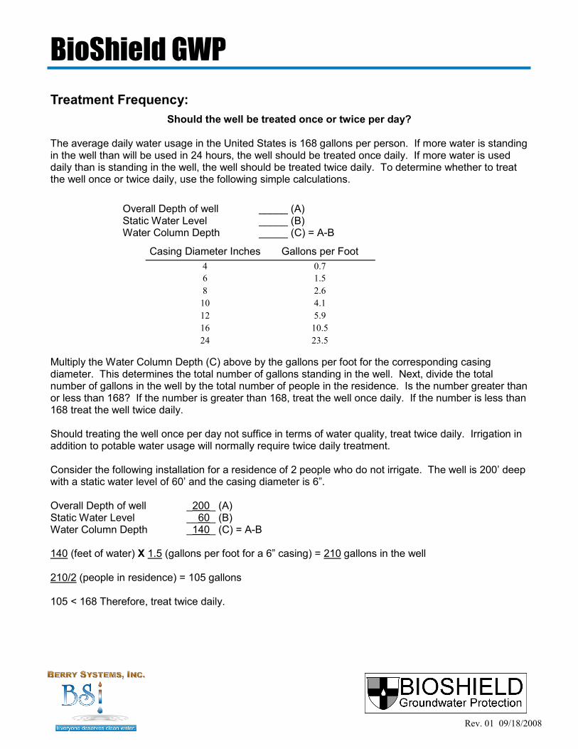
Should the well be treated once or twice per day? The average daily water usage in the United States is 168 gallons per person. If more water is standing in the well than will be used in 24 hours, the well should be treated once daily. If more water is used daily than is standing in the well, the well should be treated twice daily. To determine whether to treat the well once or twice daily, use the following simple calculations.
Overall Depth of well _____ (A) Static Water Level _____ (B) Water Column Depth _____ (C) = A-B
Casing Diameter Inches Gallons per Foot
4 0.7
6 1.5
8 2.6
10 4.1
12 5.9
16 10.5
24 23.5
Treatment Frequency:
Multiply the Water Column Depth (C) above by the gallons per foot for the corresponding casing diameter. This determines the total number of gallons standing in the well. Next, divide the total number of gallons in the well by the total number of people in the residence. Is the number greater than or less than 168? If the number is greater than 168, treat the well once daily. If the number is less than 168 treat the well twice daily. Should treating the well once per day not suffice in terms of water quality, treat twice daily. Irrigation in addition to potable water usage will normally require twice daily treatment. Consider the following installation for a residence of 2 people who do not irrigate. The well is 200’ deep with a static water level of 60’ and the casing diameter is 6‖. Overall Depth of well _200_ (A) Static Water Level __60_ (B) Water Column Depth _140_ (C) = A-B 140 (feet of water) X 1.5 (gallons per foot for a 6‖ casing) = 210 gallons in the well 210/2 (people in residence) = 105 gallons 105 < 168 Therefore, treat twice daily.
BioShield GWP

Rev. 01 09/18/2008
Set the unit run time in accordance with the BioShield Selection Program on CD included. Following initial treatment cycle, check HaloSan residual level at the tap closest to the well using HaloSan Test Kit for bromine according to package directions. A biofouled well is not likely to register any HaloSan residual. Residual levels should not exceed 3 mg/L. If the residual level does exceed 3mg/L, reduce run time. Pump water to waste. Wait 12 hours. Following next cycle check residual again. One(1) hour after treatment, the residual should be 0.2 mg/L or less. Chemical presence should not be detectable by smell. Once the well has been cleared of biofouling, reduce run time to achieve a treatment level approaching 1mg/L in accordance with the BioShield Selection Program (at www.berrysystemsinc.com/brochure.html). The goal is to maintain the well with minimum chemical intervention. See After Install Checklist for further information on HaloSan.
Treatment run time:
HaloSan Residual Test Kit The BioShield installation kit comes with a kit for determining the chemical residual level in the well wa-ter. The HaloSan Test Kit Instructions are as follows:
1. Remove cover from tester.
2. Hold tester with colorimetric chart facing you. Fill reservoir on the right with water from the well.
3. Remove DPD No. 1 test tablet from the foil package. Drop the tablet into the water in the
tester.
4. Place cover onto tester and seal. Shake tester and wait 30 seconds until tablet completely dissolves. Match water color in tester to the pink graduation on the right. Read residual.
Ensure that residual does not exceed 3 Br2 mg/L.
For chemical testing only!
Never take tablets!
Keep out of reach of children.
Read the test results when the tablet has completely dissolved and 30 seconds have passed. Do not retain the chemicals in the reservoir and read the results several minutes or hours later. Any later result will not be accurate! Discard contents and rinse reservoir. Based upon the reading, the run time may need to be adjusted. See ―After Install Check List‖ included with the installation instructions for further instructions on obtaining the best chemical treatment level for your well.
BioShield GWP
Biological and Chemical Processes
Important Information for Well Owner
Groundwater wells harbor a variety of nuisance bacteria, opportunistic bacteria, and pathogenic bacteria. Most states require only a one time disinfection and test for Total Coliform Count when the well is first constructed. However, it is not uncommon for wells showing no coliform bacteria to have very large bacterial populations. According to the EPA, ―Disinfectants themselves can react with naturally-occurring materials in the water to form byproducts, such as trihalomethanes and haloacetic acids, which may pose health risks.‖ BioShield is designed to safely clear the debris from the bacterial biofouling of the well. When the level of bacteria decreases, the level of disinfection by-products will decrease. For the reasons listed above, we recommend you use an alternate source of water for drinking and food preparation until the well and pipes are free of any debris and the water is consistently running clear. HaloSan is certified by NSF for potable water. Biofouling of the well is eliminated and maintained below this certification level. Should you be concerned about disinfection by-products in your well, Underwriters Laboratories will test the water according to their UL Drink Well program. See www.uldrinkwell.com for more information. Also, activated carbon may be used to remove disinfection byproducts. BioShield is the most effective system for killing bacteria in the well. The system runtime is dependent upon the well construction and the level of biofouling in the well. A biofouled well will deposit both organic and inorganic material, including ferric hydroxides, in the well proper, the pump, the riser, the supply line and into the plumbing in the residence or irrigation system in an amount directly proportional to the level of biofouling. When the bacteria in the well begin to be eliminated, these particles will come loose and migrate downstream. Be aware of the resulting debris and protect any peripheral water treatment devices you may have accordingly.
BioShield GWP
Rev. 01 09/18/2008

Rev. 02 08/09/2010
After Installation Check List
Important Information for Well Owner To clear the well and distribution piping of the biofouling materials, which have built up over time in the well and plumbing, please follow these simple directions:
Use the BioShield Selection Program (at www.berrysystemsinc.com/brochure.html) to calculate the run time for the well and program the timer accordingly.
Each morning run the spigot closest to the well until the water runs clear. Then run water from each faucet in the house until the water runs clear.
This is to be done daily until the well and pipes are free of any debris caused by biofouling. Depending on the level of biofouling at your site, this regimen will need to be done for a period of several days to several weeks. Check the residual level of the HaloSan in the water at the kitchen tap using the test kit enclosed in the installation kit. Ensure that the residual level does not exceed 3 mg/L. Should you get a reading in excess of 3 mg/L go to the well and run water to waste until the level is reduced and reduce the run time accordingly. One hour after the cycle runs, a residual of 0.2 or less is best. The timer should be set accordingly to maintain this level. Once BioShield has cleaned the well and pipes of the biofouling the run time may be reduced to maintain the well biologically. Up to a 50% reduction in run time may be sufficient. You are the water treatment operator. Many variables influence the bacteria level in well water. Use the test kit to monitor your well water residual and adjust the runtime as needed. Never use a runtime that yields a residual higher than 3 mg/L. Note: (See HaloSan instructions for additional information on testing for the HaloSan residual.) Should you ever smell the chemical, test the water using the residual test kit and reduce the run time to reduce the residual level. Also, should the water quality diminish, immediately check the canister to determine whether it has a sufficient quantity of HaloSan in it. If the canister is ½ full or better, an upward adjustment of the timer may need to be made. Any adjustments to the timer should be done in small increments and sufficient time, at least a few days, should be allowed to lapse before additional adjustments are made. An exception to this would be a high residual reading where a larger downward adjustment might be required. Do not use bleach products in your clothes washer as they may oxidize the iron and stain clothes. Contact Berry Systems, Inc. if further information as needed.
BioShield GWP

926 Carolina Drive Lugoff, SC 29078
Phone: (803) 408-6730 Fax: (803) 408-6784
www.berrysystemsinc.com