Embed Size (px)
Citation preview

PRESSURE (BAR)
9.0 9.0
7.5 7.5
9.0 9.0
9.0 9.0
9.0 9.0
ContiPressureCheck™
The tire pressure monitoring system
USA Installation Manual

3
CPC
US
AContent
1 General ...........................................................................................6
1.1 Information on this Installation Manual ..............................................6
1.2 Liability disclaimer .............................................................................7
1.3 Explanation of symbols .....................................................................7
1.4 Abbreviations.....................................................................................8
1.5 Warnings ...........................................................................................9
1.6 Copyright .........................................................................................10
1.7 Warranty terms ................................................................................10
1.8 Manufacturer's address ...................................................................10
1.9 After-sales service ...........................................................................10
2 Safety ...........................................................................................11
2.1 General ............................................................................................11
2.2 Prohibition of modifications .............................................................11
2.3 Intended use ....................................................................................12
2.4 Fundamental safety instructions ......................................................13
2.5 Particular hazards ............................................................................14
2.6 Qualification for installation .............................................................15
2.7 Personal protective equipment ........................................................16
3 Technical data ..............................................................................17
3.1 Tire sensor .......................................................................................17
3.2 Central control unit ..........................................................................17
3.3 Auxiliary receiver (optional) ..............................................................17
3.4 Display ............................................................................................18
3.5 Hand-held tool .................................................................................18
3.6 Pressure control indicator ................................................................18
4 Design and Function ....................................................................19
4.1 Description of function ....................................................................19
4.2 Overview .........................................................................................19
4.3 Tire sensor .......................................................................................20
4.4 Central control unit (CCU)................................................................21
4.5 Auxiliary receiver (optional) ..............................................................22
4.6 Display ............................................................................................23
Table of Contents
4
CPC
US
A
4.7 Mounting brackets ...........................................................................24
4.8 Wiring truck/bus with auxiliary receiver ...........................................25
4.9 Pressure control indicator trailer/semi-trailer ...................................26
4.10 Wiring trailer/semi-trailer .................................................................27
4.11 Hand-held tool, diagnostic cable .....................................................28
4.12 Spare parts ......................................................................................29
5 Installation ....................................................................................30
5.1 Scope of supply ..............................................................................30
5.2 Disposal of the packaging ...............................................................30
5.3 General instruction ..........................................................................31
5.4 Installation of the tire sensor ...........................................................31
5.5 Final inspection of the bonding of the rubber container ..................41
5.6 Tire sensor activation before fitting tire ............................................41
5.7 Removing ventilation ribs in the bonding area .................................42
5.8 Retreading .......................................................................................43
5.9 Continued use of the tire sensor after changing a tire .....................43
5.10 Use of balancing substances in commercial vehicle tires ................44
5.11 Installation of the central control unit on HGV/bus ..........................45
5.12 Installing an auxiliary receiver (optional) ..........................................47
5.13 Installation of the wiring harness from central control unit to auxiliary receiver ..........................................................................49
5.14 Installation of the wiring harness from central control unit to fuse box ......................................................................................50
5.15 Installation of the display .................................................................51
5.16 Installation of the wiring harness from display to fuse box ..............52
5.17 Installation of the central control unit and an optional auxiliary receiver on the trailer/semi-trailer ....................................................54
5.18 Installation and adjustment of the pressure control indicator. ..........55
5.19 Installation of the wiring harness from the central control unit to pressure control indicator, diagnostic port and distributor box........63
5.20 Checks after installation ..................................................................64
Table of Contents
5
CPC
US
A
6 Initialization using hand-held tool .................................................65
7 Test Drive for System Testing .......................................................68
7.1 Test drive for system testing on the HGV/bus ..................................68
7.2 Test drive for system testing on the semi-trailer ..............................70
7.3 Preparation for repeating a test drive ..............................................71
8 Modification of the CPC system configuration .............................72
8.1 Automatic wheel change detection (optional function)* ...................72
8.2 Manual adaptations with the hand-held tool ....................................73
9 Documentation of system installation ...........................................73
10 Information on the system ............................................................74
10.1 General ............................................................................................74
10.2 Operation ........................................................................................74
11 Diagnostics ..................................................................................74
11.1 Diagnostics via display ....................................................................77
12 Dismantling and Disposal .............................................................80
12.1 Dismantling......................................................................................80
12.2 Disposal ..........................................................................................82
13 Declaration of conformity .............................................................84
14 Certifications ................................................................................84
14.1 Radio permit ....................................................................................84
14.2 General operating permit .................................................................84
14.3 ADR .................................................................................................84
15 Index ............................................................................................85
6
General
CPC
US
A
General1
Information on this Installation Manual1.1
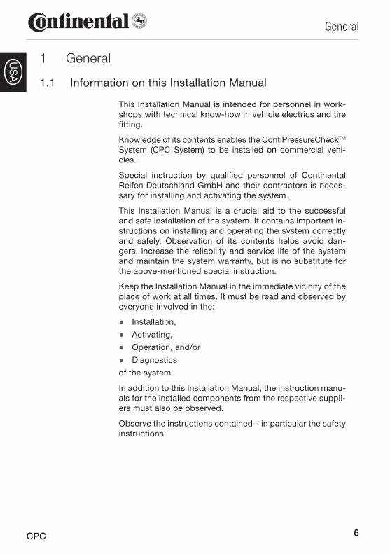
This Installation Manual is intended for personnel in work-shops with technical know-how in vehicle electrics and tire fitting.
Knowledge of its contents enables the ContiPressureCheckTM
System (CPC System) to be installed on commercial vehi-cles.
Special instruction by qualified personnel of Continental Reifen Deutschland GmbH and their contractors is neces-sary for installing and activating the system.
This Installation Manual is a crucial aid to the successful and safe installation of the system. It contains important in-structions on installing and operating the system correctly and safely. Observation of its contents helps avoid dan-gers, increase the reliability and service life of the system and maintain the system warranty, but is no substitute for the above-mentioned special instruction.
Keep the Installation Manual in the immediate vicinity of the place of work at all times. It must be read and observed by everyone involved in the:
Installation, ●Activating, ●Operation, and/or ●Diagnostics ●
of the system.
In addition to this Installation Manual, the instruction manu-als for the installed components from the respective suppli-ers must also be observed.
Observe the instructions contained – in particular the safety instructions.
7
General
CPC
US
A
1.2 Liability disclaimer
The manufacturer assumes no liability for damage and operational faults resulting from:
Failure to observe this Installation Manual, ■Use for other than the intended purpose, ■Installation by unqualified or insufficiently qualified ■personnel,
Faulty installation, ■Use of other than original equipment manufacturer ■(OEM) spare parts and accessories,
Technical modifications and changes not approved by ■the manufacturer,
Failure to perform the prescribed visual inspection (see ■Chapter 5.5 Final inspection of the bonding of the rubber container) after installation of the tire sensor.
1.3 Explanation of symbols
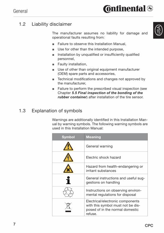
Warnings are additionally identified in this Installation Man-ual by warning symbols. The following warning symbols are used in this Installation Manual:
Symbol Meaning
General warning
Electric shock hazard
Hazard from health-endangering or irritant substances
General instructions and useful sug-gestions on handling
Instructions on observing environ-mental regulations for disposal
Electrical/electronic components with this symbol must not be dis-posed of in the normal domestic refuse.
8
General
CPC
US
A
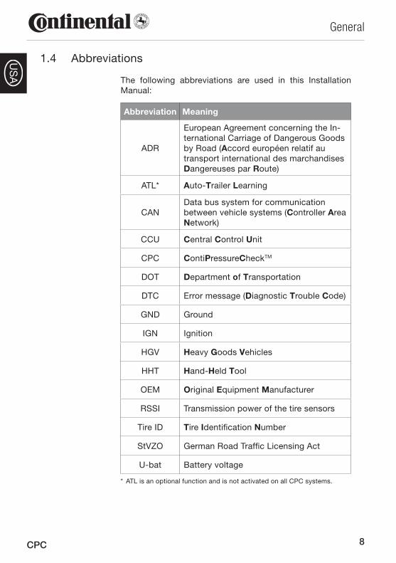
1.4 Abbreviations
The following abbreviations are used in this Installation Manual:
Abbreviation Meaning
ADR
European Agreement concerning the In-ternational Carriage of Dangerous Goods by Road (Accord européen relatif au transport international des marchandises Dangereuses par Route)
ATL* Auto-Trailer Learning
CANData bus system for communication between vehicle systems (Controller Area Network)
CCU Central Control Unit
CPC ContiPressureCheckTM
DOT Department of Transportation
DTC Error message (Diagnostic Trouble Code)
GND Ground
IGN Ignition
HGV Heavy Goods Vehicles
HHT Hand-Held Tool
OEM Original Equipment Manufacturer
RSSI Transmission power of the tire sensors
Tire ID Tire Identification Number
StVZO German Road Traffic Licensing Act
U-bat Battery voltage
* ATL is an optional function and is not activated on all CPC systems.
9
General
CPC
US
A
1.5 Warnings
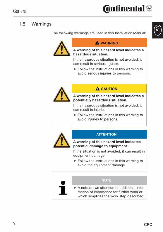
The following warnings are used in this Installation Manual:
WARNING
A warning of this hazard level indicates a hazardous situation.
If the hazardous situation is not avoided, it can result in serious injuries.
Follow the instructions in this warning to ►avoid serious injuries to persons.
CAUTION
A warning of this hazard level indicates a potentially hazardous situation.
If the hazardous situation is not avoided, it can result in injuries.
Follow the instructions in this warning to ►avoid injuries to persons.
ATTENTION
A warning of this hazard level indicates potential damage to equipment.
If the situation is not avoided, it can result in equipment damage.
Follow the instructions in this warning to ►avoid the equipment damage.
NOTE
A note draws attention to additional infor- ►mation of importance for further work or which simplifies the work step described.

10
General
CPC
US
A
Copyright1.6
This Installation Manual and all documents supplied with this system are protected by copyright.
These documents may not be duplicated or made acces-sible to third parties, in particular to competing compa-nies, without the express approval von Continental Reifen Deutschland GmbH.
Please note that this system is protected by patent.
1.7 Warranty terms
The warranty can be found at:www.contipressurecheck.com
1.8 Manufacturer's address
Continental Reifen Deutschland GmbH
Büttnerstraße 25
30165 Hannover
Germany
www.contipressurecheck.com
1.9 After-sales service
In the event of technical questions on the system, first con-tact an authorized workshop.
Further information can also be found at:www.contipressurecheck.com
11
Safety
CPC
US
ASafety2
General2.1
This chapter contains important information on all aspects of safety.
Apart from the general safety instructions given in this chapter, additional safety instructions relevant to the op-erations covered are given in each chapter.
Hazards that could occur during a particular work step are described before the instructions for the step.
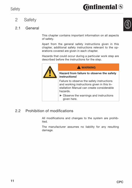
WARNING
Hazard from failure to observe the safety instructions!
Failure to observe the safety instructions and working instructions given in this In-stallation Manual can create considerable hazards.
Observe the warnings and instructions ►given here.
Prohibition of modifications2.2
All modifications and changes to the system are prohib-ited.
The manufacturer assumes no liability for any resulting damage.
12
Safety
CPC
US
A
2.3 Intended use
This system is intended exclusively for measuring the in-flation pressure in truck/bus tires and for transmitting the values by radio to an external evaluation unit.
Use for any other or further purpose does not constitute an intended use.
WARNING
Hazard from use for other than the in-tended purpose!
Any use other than and/or going beyond the intended use of the device can lead to dangerous situations.
Use the system only for its intended ►purpose.
Comply with all instructions in this Instal- ►lation Manual.
No claims of any kind will be accepted for damage resulting from use for other than the intended purpose.
The risks associated with such improper use shall be borne solely by the user.
Use of the tire sensors2.3.1
The operator must ensure that tires in which sensors are installed are only used on vehicles where monitoring by the CPC system is ensured.
This also includes the monitoring of the trailer via the auxil-iary receiver on the drawing vehicle.
Before further use of the tires on other vehicles where moni-toring by the CPC system is not assured, remove the sen-sors from the tires.
13
Safety
CPC
US
A
2.4 Fundamental safety instructions
Observe the following instructions to avoid accidents dur-ing the installation of the system:
Observe the vehicle manufacturer's safety instructions. ■Take all necessary precautions before jacking up the ■vehicle (e.g. to prevent rolling away).
Observe the safety at work regulations of the country ■in question.
Ensure adequate lighting conditions at the place of ■work.
The place of work and the tools used must be in a ■clean and safe condition.
Defective components may only be replaced with OEM ■spare parts. Only these parts ensure that the safety requirements are satisfied.
During use of the CPC system, check all screw and ■plug connections at regular intervals.
14
Safety
CPC
US
A
2.5 Particular hazards
CAUTION
Danger of short-circuit!
Danger of short-circuits when working on the vehicle electrical system.
Observe the vehicle manufacturer's ►safety instructions.
Switch off all electrical equipment before ►disconnecting the battery terminals.
Disconnect the minus terminal ► before the plus terminal.
Do not kink cables, place cables under strain or lay ■cables over sharp edges.
Do not install cables in the vicinity of rotating, moving ■or hot parts.
For cables, observe a bending radius of at least 15 mm ■(0.6 in.), for corrugated tubes a bending radius of at least 35 mm (1.4 in.).
Ensure that plug connectors are clean and dry, and ■that they are securely locked after connection.
Secure the wiring harness in a suitable manner max. ■10 cm (4 in.) before and after each plug connection.
Pay attention to effective sealing of the cable lead- ■throughs in the vehicle cab and in fuse and distributor boxes.
Use only suitable tools for stripping the cable insula- ■tion and for crimping cable shoes.
The installation of the CPC system on the vehicle (in ■particular when connecting to the power supply) must not influence the function of other systems on the vehicle (e.g. brake system or light system).

15
Safety
CPC
US
A
2.6 Qualification for installation
WARNING
Injury hazard with insufficient qualifica-tion.
Installation by unqualified personnel can result in considerable personal injury and equipment damage.
Have all work carried out only by appro- ►priately qualified personnel.
The following qualifications are specified in this Installation Manual:
Qualified personnel ■ deemed capable of independently carrying out the work assigned to them and of recognizing and avoid-ing possible dangers due to their technical training, know-how and experience and their knowledge of the relevant regulations.
The system may only be installed by persons who have been trained for this work and who have technical know-how of vehicle electronics and tire fitting.
NOTE
The system may only be installed by spe- ►cially authorized garages.
16
Safety
CPC
US
A
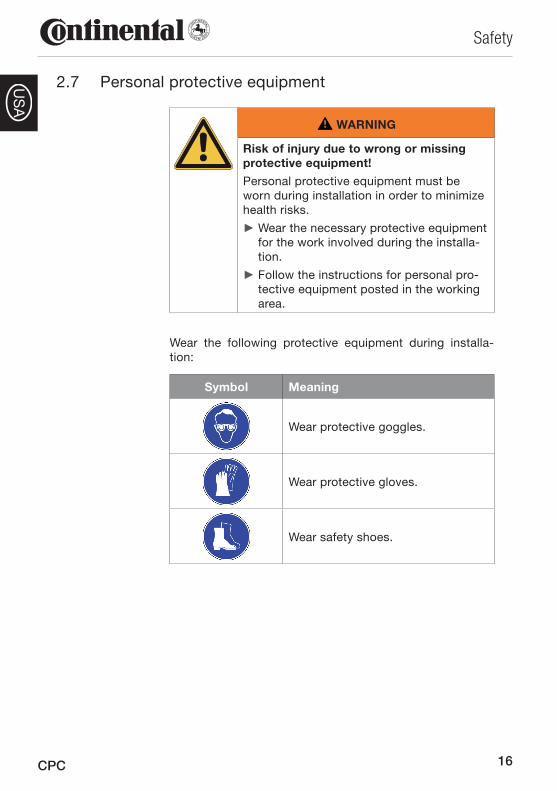
2.7 Personal protective equipment
WARNING
Risk of injury due to wrong or missing protective equipment!
Personal protective equipment must be worn during installation in order to minimize health risks.
Wear the necessary protective equipment ►for the work involved during the installa-tion.
Follow the instructions for personal pro- ►tective equipment posted in the working area.
Wear the following protective equipment during installa-tion:
Symbol Meaning
Wear protective goggles.
Wear protective gloves.
Wear safety shoes.
17
Technical data
CPC
US
ATechnical data3
NOTE
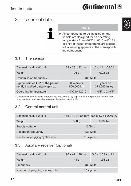
All components to be installed on the ►vehicle are designed for an operating temperature from -40°C to 85°C (-40 °F to 185 °F). If these temperatures are exceed-ed, a warning appears at the correspond-ing component.
3.1 Tire sensor
Dimensions (L x W x H) 38 x 28 x 22 mm 1.5 x 1.1 x 0.86 in.
Weight 26 g 0.92 oz
Transmission frequency 433 MHz
Typical service life* of the perma-nently installed battery approx.
6 vears or 600,000 km
6 years or 373,000 miles
Operating temperature -40°C to 120°C -40°F to 248°F
* Constantly high tire inside temperatures (caused e.g. by high ambient temperature, low tire pres-sure, etc.) can lead to a shortening on the battery service life.
3.2 Central control unit
Dimensions (L x W x H) 165 x 121 x 65 mm 6.5 x 4.76 x 2.56 in.
Weight 390 g 0.86 lbs
Supply voltage 12/24 V
Reception frequency 433 MHz
Number of plugging cycles, min. 10 cycles
3.3 Auxiliary receiver (optional)
Dimensions (L x W x H) 90 x 42 x 28 mm 3.5 x 1.65 x 1.1 in.
Weight 44 g 1.55 oz
Frequency 433 MHz
Number of plugging cycles, min. 10 cycles
18
Technical data
CPC
US
A
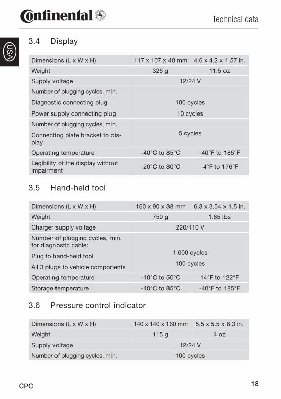
3.4 Display
Dimensions (L x W x H) 117 x 107 x 40 mm 4.6 x 4.2 x 1.57 in.
Weight 325 g 11.5 oz
Supply voltage 12/24 V
Number of plugging cycles, min.
Diagnostic connecting plug
Power supply connecting plug
100 cycles
10 cycles
Number of plugging cycles, min.
Connecting plate bracket to dis-play
5 cycles
Operating temperature -40°C to 85°C -40°F to 185°F
Legibility of the display without impairment
-20°C to 80°C -4°F to 176°F
3.5 Hand-held tool
Dimensions (L x W x H) 160 x 90 x 38 mm 6.3 x 3.54 x 1.5 in.
Weight 750 g 1.65 lbs
Charger supply voltage 220/110 V
Number of plugging cycles, min. for diagnostic cable:
Plug to hand-held tool
All 3 plugs to vehicle components
1,000 cycles
100 cycles
Operating temperature -10°C to 50°C 14°F to 122°F
Storage temperature -40°C to 85°C -40°F to 185°F
3.6 Pressure control indicator
Dimensions (L x W x H) 140 x 140 x 160 mm 5.5 x 5.5 x 6.3 in.
Weight 115 g 4 oz
Supply voltage 12/24 V
Number of plugging cycles, min. 100 cycles
19
Design and Function
CPC
US
ADesign and Function4
4.1 Description of function
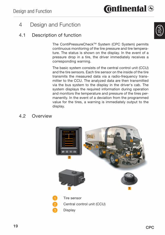
The ContiPressureCheckTM System (CPC System) permits continuous monitoring of the tire pressure and tire tempera-ture. The status is shown on the display. In the event of a pressure drop in a tire, the driver immediately receives a corresponding warning.
The basic system consists of the central control unit (CCU) and the tire sensors. Each tire sensor on the inside of the tire transmits the measured data via a radio-frequency trans-mitter to the CCU. The analyzed data are then transmitted via the bus system to the display in the driver's cab. The system displays the required information during operation and monitors the temperature and pressure of the tires per-manently. In the event of a deviation from the programmed value for the tires, a warning is immediately output to the display.
Overview4.2
PRESSURE (BAR)
9.0 9.0
7.5 7.5
9.0 9.0
9.0 9.0
9.0 9.0
2 1
31
1
1
11
1
2
2
3
1 Tire sensor
2 Central control unit (CCU)
3 Display
20
Design and Function
CPC
US
A
4.3 Tire sensor
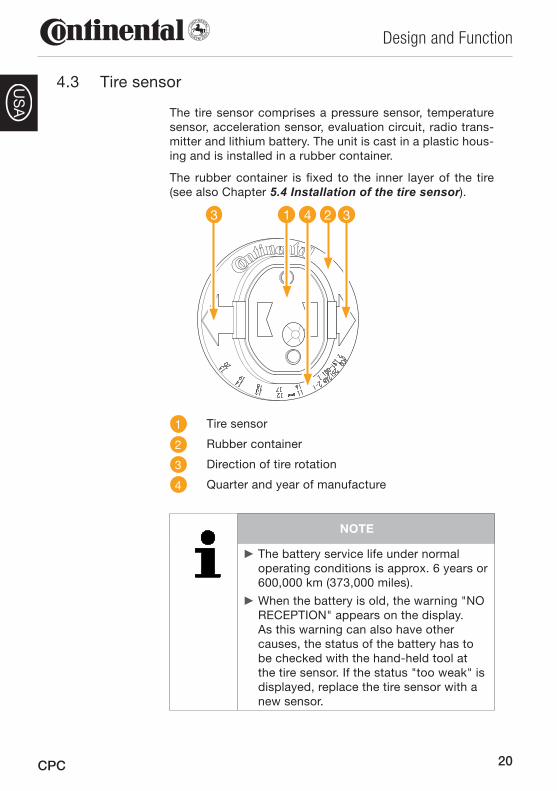
The tire sensor comprises a pressure sensor, temperature sensor, acceleration sensor, evaluation circuit, radio trans-mitter and lithium battery. The unit is cast in a plastic hous-ing and is installed in a rubber container.
The rubber container is fixed to the inner layer of the tire (see also Chapter 5.4 Installation of the tire sensor).
13 324
1 Tire sensor
2 Rubber container
3 Direction of tire rotation
4 Quarter and year of manufacture
NOTE
The battery service life under normal ►operating conditions is approx. 6 years or 600,000 km (373,000 miles).
When the battery is old, the warning "NO ►RECEPTION" appears on the display. As this warning can also have other causes, the status of the battery has to be checked with the hand-held tool at the tire sensor. If the status "too weak" is displayed, replace the tire sensor with a new sensor.
21
Design and Function
CPC
US
A
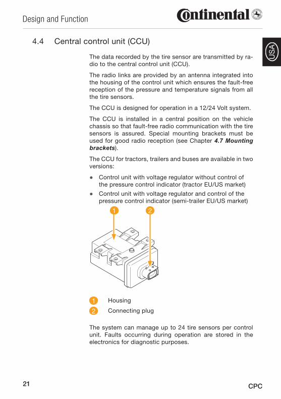
4.4 Central control unit (CCU)
The data recorded by the tire sensor are transmitted by ra-dio to the central control unit (CCU).
The radio links are provided by an antenna integrated into the housing of the control unit which ensures the fault-free reception of the pressure and temperature signals from all the tire sensors.
The CCU is designed for operation in a 12/24 Volt system.
The CCU is installed in a central position on the vehicle chassis so that fault-free radio communication with the tire sensors is assured. Special mounting brackets must be used for good radio reception (see Chapter 4.7 Mounting brackets).
The CCU for tractors, trailers and buses are available in two versions:
Control unit with voltage regulator without control of ●the pressure control indicator (tractor EU/US market)
Control unit with voltage regulator and control of the ●pressure control indicator (semi-trailer EU/US market)
1 2
1 Housing
2 Connecting plug
The system can manage up to 24 tire sensors per control unit. Faults occurring during operation are stored in the electronics for diagnostic purposes.
22
Design and Function
CPC
US
A
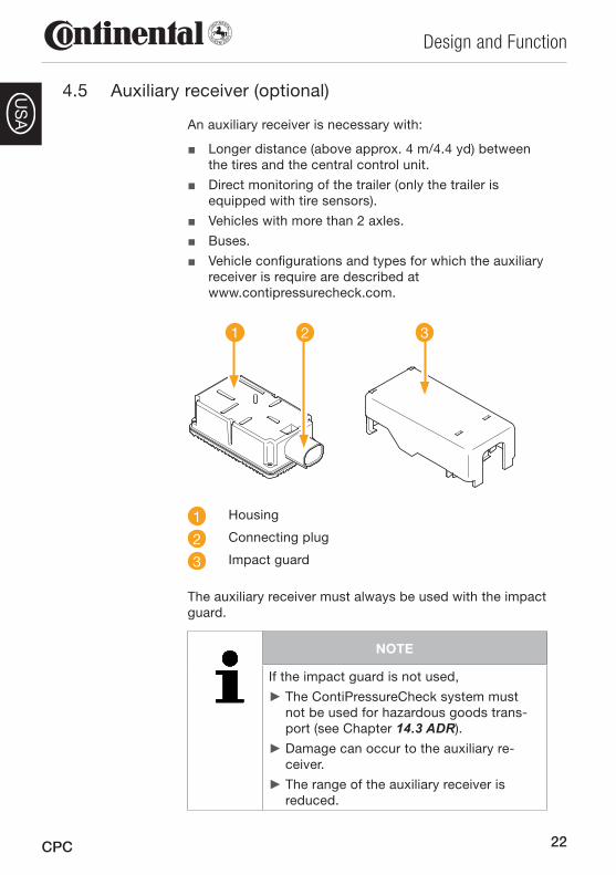
4.5 Auxiliary receiver (optional)
An auxiliary receiver is necessary with:
Longer distance (above approx. 4 m/4.4 yd) between ■the tires and the central control unit.
Direct monitoring of the trailer (only the trailer is ■equipped with tire sensors).
Vehicles with more than 2 axles. ■Buses. ■Vehicle configurations and types for which the auxiliary ■receiver is require are described at www.contipressurecheck.com.
21 3
1 Housing
2 Connecting plug
3 Impact guard
The auxiliary receiver must always be used with the impact guard.
NOTE
If the impact guard is not used,
The ContiPressureCheck system must ►not be used for hazardous goods trans-port (see Chapter 14.3 ADR).
Damage can occur to the auxiliary re- ►ceiver.
The range of the auxiliary receiver is ►reduced.
23
Design and Function
CPC
US
A
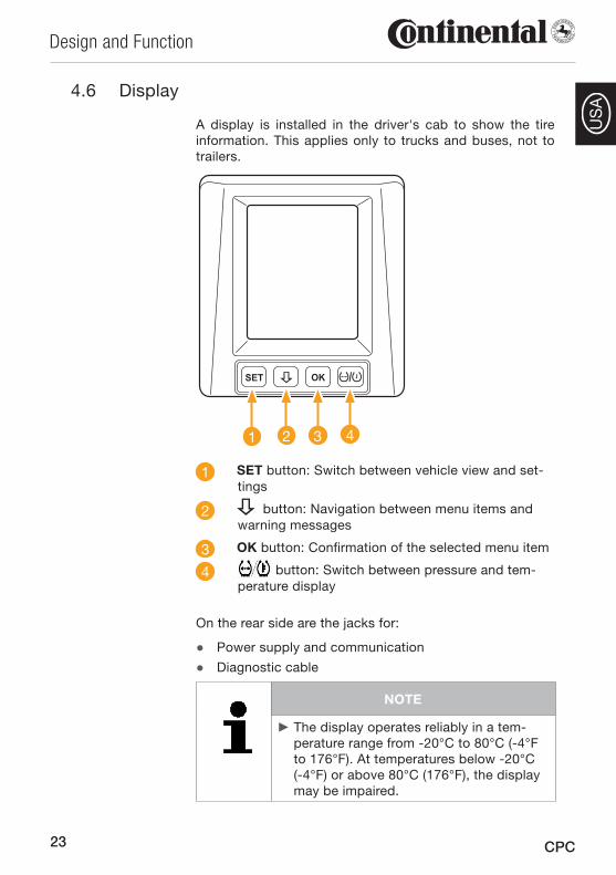
4.6 Display
A display is installed in the driver's cab to show the tire information. This applies only to trucks and buses, not to trailers.
1 2 3 4
1 SET button: Switch between vehicle view and set-tings
2 button: Navigation between menu items and warning messages
3 OK button: Confirmation of the selected menu item
4 button: Switch between pressure and tem-perature display
On the rear side are the jacks for:
Power supply and communication ●Diagnostic cable ●
NOTE
The display operates reliably in a tem- ►perature range from -20°C to 80°C (-4°F to 176°F). At temperatures below -20°C (-4°F) or above 80°C (176°F), the display may be impaired.
24
Design and Function
CPC
US
A
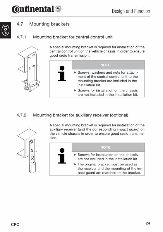
Mounting brackets4.7
Mounting bracket for central 4.7.1 control unit
A special mounting bracket is required for installation of the central control unit on the vehicle chassis in order to ensure good radio transmission.
NOTE
Screws, washers and nuts for attach- ►ment of the central control unit to the mounting bracket are included in the installation kit.
Screws for installation on the chassis ►are not included in the installation kit.
Mounting bracket for 4.7.2 auxiliary receiver (optional)
A special mounting bracket is required for installation of the auxiliary receiver (and the corresponding impact guard) on the vehicle chassis in order to ensure good radio transmis-sion.
NOTE
Screws for installation on the chassis ►are not included in the installation kit.
The original bracket must be used as ►the receiver and the mounting of the im-pact guard are matched to the bracket.
25
Design and Function
CPC
US
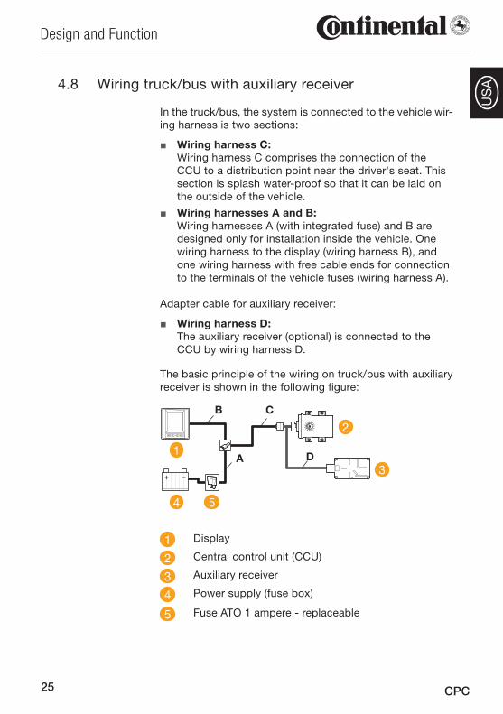
AWiring 4.8 truck/bus with auxiliary receiver
In the truck/bus, the system is connected to the vehicle wir-ing harness is two sections:
Wiring harness C: ■ Wiring harness C comprises the connection of the CCU to a distribution point near the driver's seat. This section is splash water-proof so that it can be laid on the outside of the vehicle.
Wiring harnesses A and B: ■ Wiring harnesses A (with integrated fuse) and B are designed only for installation inside the vehicle. One wiring harness to the display (wiring harness B), and one wiring harness with free cable ends for connection to the terminals of the vehicle fuses (wiring harness A).
Adapter cable for auxiliary receiver:
Wiring harness D: ■ The auxiliary receiver (optional) is connected to the CCU by wiring harness D.
The basic principle of the wiring on truck/bus with auxiliary receiver is shown in the following figure:
1
2
3
4
A
B C
D
5
1 Display
2 Central control unit (CCU)
3 Auxiliary receiver
4 Power supply (fuse box)
5 Fuse ATO 1 ampere - replaceable
26
Design and Function
CPC
US
A
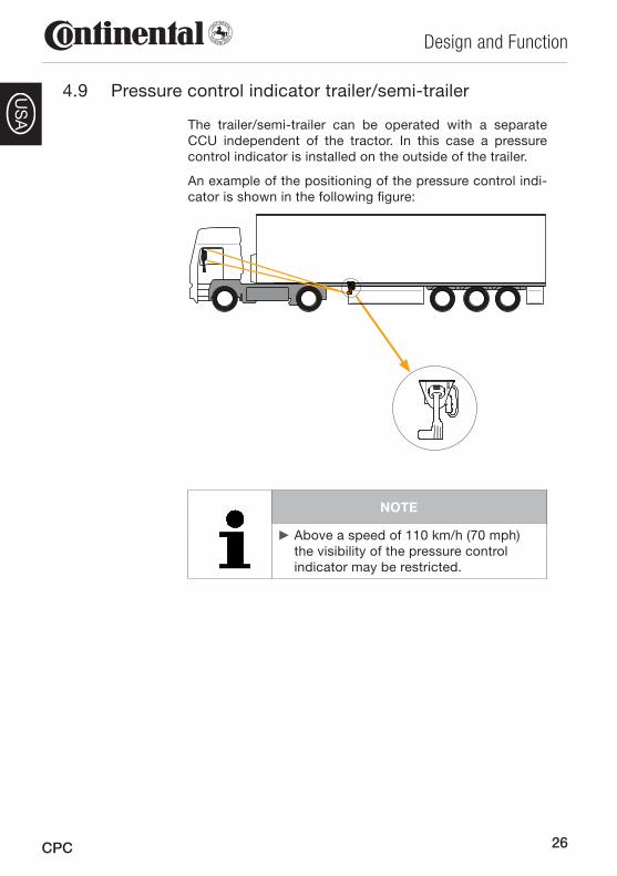
4.9 Pressure control indicator trailer/semi-trailer
The trailer/semi-trailer can be operated with a separate CCU independent of the tractor. In this case a pressure control indicator is installed on the outside of the trailer.
An example of the positioning of the pressure control indi-cator is shown in the following figure:
NOTE
Above a speed of 110 km/h (70 mph) ►the visibility of the pressure control indicator may be restricted.
27
Design and Function
CPC
US
A
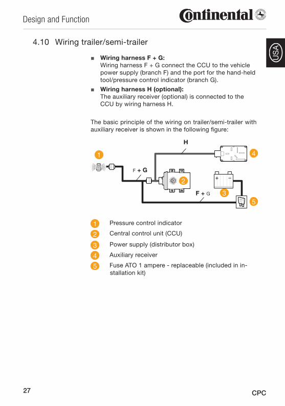
Wiring 4.10 trailer/semi-trailer
Wiring harness F + G: ■ Wiring harness F + G connect the CCU to the vehicle power supply (branch F) and the port for the hand-held tool/pressure control indicator (branch G).
Wiring harness H (optional): ■The auxiliary receiver (optional) is connected to the CCU by wiring harness H.
The basic principle of the wiring on trailer/semi-trailer with auxiliary receiver is shown in the following figure:
H
2
3
F + G
F + G
1 4
5
1 Pressure control indicator
2 Central control unit (CCU)
3 Power supply (distributor box)
4 Auxiliary receiver
5 Fuse ATO 1 ampere - replaceable (included in in-stallation kit)
28
Design and Function
CPC
US
A
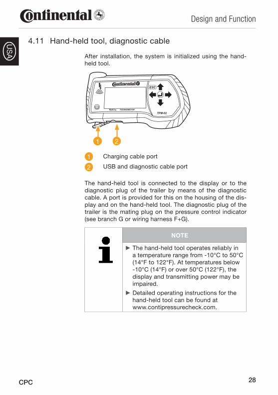
4.11 Hand-held tool, diagnostic cable
After installation, the system is initialized using the hand-held tool.
1 2
1 Charging cable port
2 USB and diagnostic cable port
The hand-held tool is connected to the display or to the diagnostic plug of the trailer by means of the diagnostic cable. A port is provided for this on the housing of the dis-play and on the hand-held tool. The diagnostic plug of the trailer is the mating plug on the pressure control indicator (see branch G or wiring harness F+G).
NOTE
The hand-held tool operates reliably in ►a temperature range from -10°C to 50°C (14°F to 122°F). At temperatures below -10°C (14°F) or over 50°C (122°F), the display and transmitting power may be impaired.
Detailed operating instructions for the ►hand-held tool can be found at www.contipressurecheck.com.
29
Design and Function
CPC
US
ANOTE
In the event of a fault in the hand-held ►tool, a second-hand replacement tool will generally be supplied within 24 hours of receipt of the defective tool, but not later than within 72 hours.
The costs for the replacement are de- ►termined by the relevant provisions of the warranty (see Chapter 1.7 Warranty terms).
Spare parts4.12
The available spare parts and the corresponding article numbers can be found at www.contipressurecheck.com.
30
Installation
CPC
US
A
Installation5
Scope of supply5.1
NOTE
An overview of the different vehicle ►configurations and vehicle types for which the various kits of the ContiPres-sureCheckTM may be used can be found at www.contipressurecheck.com.
Check the completeness of the installa- ►tion kit against the enclosed delivery note and inspect all parts for visible damages. The corresponding parts lists can be found at www.contipressurecheck.com.
On delivery of the system, note any ►damage due to improper packaging or transport damage on the delivery note and report it to your sales contact im-mediately.
Disposal of the 5.2 packaging
The packaging protects the system against transport dam-age. The packaging materials have been selected in line with environmental and disposal aspects and are therefore recyclable.
Recycling of the packaging saves raw materials and reduces the production of waste. Dispose of packaging materials no longer required in accordance with the local regulations.
NOTE
If possible, keep the original packaging ►during the warranty period of the system in order to be able to pack components correctly in the event of a warranty claim.
31
Installation
CPC
US
A
General instruction5.3
For proper and efficient installation and in order to avoid mistakes, the sequence of the installation steps described below must be strictly observed.
NOTE
The CPC system must be installed no ►later than 2 years after packing of the kits due to ageing of the plastics (in particular of the rubber container and pressure con-trol indicator) and due to the battery shelf life of the tire sensor before use (service life in operation). Refer to the sticker on the kit for the packing date.
The service life of the Cyberbond 2250 ►adhesive is shorter (observe instructions on shelf life and method of storage on the packaging).
Installation of the tire sensor5.4
Fundamental 5.4.1 safety instructions:
Installation may ■ only be carried out by appropriately qualified personnel.
The place of work must be adequately ventilated. ■Ensure adequate lighting conditions at the place of ■work at all times.
The place of work and the tools used must be in a ■clean and safe condition.
Store all products used according to the instructions ■on the packaging.
Keep tools, cleansing agents and adhesives out of the ■reach of unauthorized persons and children.
32
Installation
CPC
US
A
5.4.2 Particular hazards
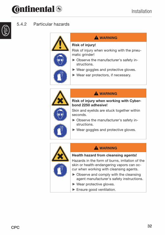
WARNING
Risk of injury!
Risk of injury when working with the pneu-matic grinder!
Observe the manufacturer's safety in- ►structions.
Wear goggles and protective gloves. ►Wear ear protectors, if necessary. ►
WARNING
Risk of injury when working with Cyber-bond 2250 adhesive!
Skin and eyelids are stuck together within seconds.
Observe the manufacturer's safety in- ►structions.
Wear goggles and protective gloves. ►
WARNING
Health hazard from cleansing agents!
Hazards in the form of burns, irritation of the skin or health-endangering vapors can oc-cur when working with cleansing agents.
Observe and comply with the cleansing ►agent manufacturer's safety instructions.
Wear protective gloves. ►Ensure good ventilation. ►
33
Installation
CPC
US
A
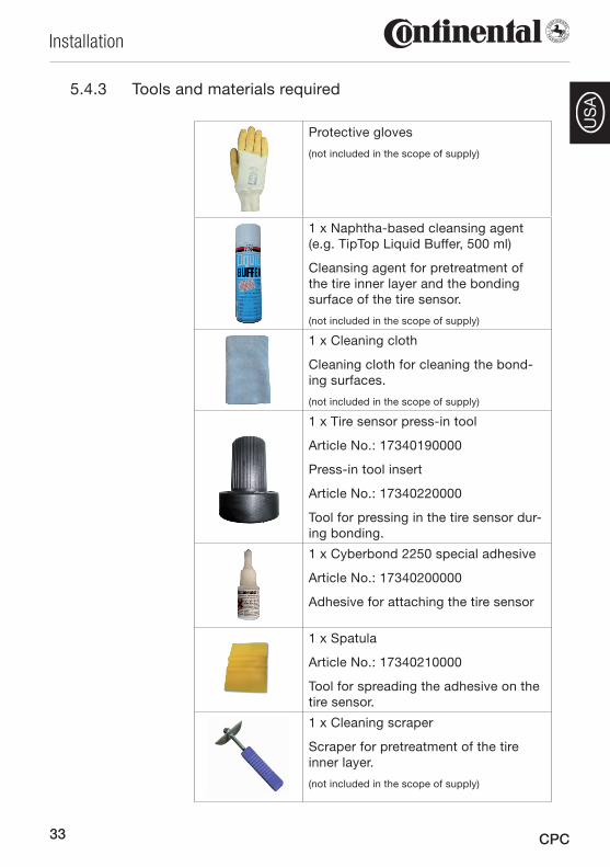
5.4.3 Tools and materials required
Protective gloves
(not included in the scope of supply)
1 x Naphtha-based cleansing agent (e.g. TipTop Liquid Buffer, 500 ml)
Cleansing agent for pretreatment of the tire inner layer and the bonding surface of the tire sensor.
(not included in the scope of supply)
1 x Cleaning cloth
Cleaning cloth for cleaning the bond-ing surfaces.
(not included in the scope of supply)
1 x Tire sensor press-in tool
Article No.: 17340190000
Press-in tool insert
Article No.: 17340220000
Tool for pressing in the tire sensor dur-ing bonding.
1 x Cyberbond 2250 special adhesive
Article No.: 17340200000
Adhesive for attaching the tire sensor
1 x Spatula
Article No.: 17340210000
Tool for spreading the adhesive on the tire sensor.
1 x Cleaning scraper
Scraper for pretreatment of the tire inner layer.
(not included in the scope of supply)
34
Installation
CPC
US
A
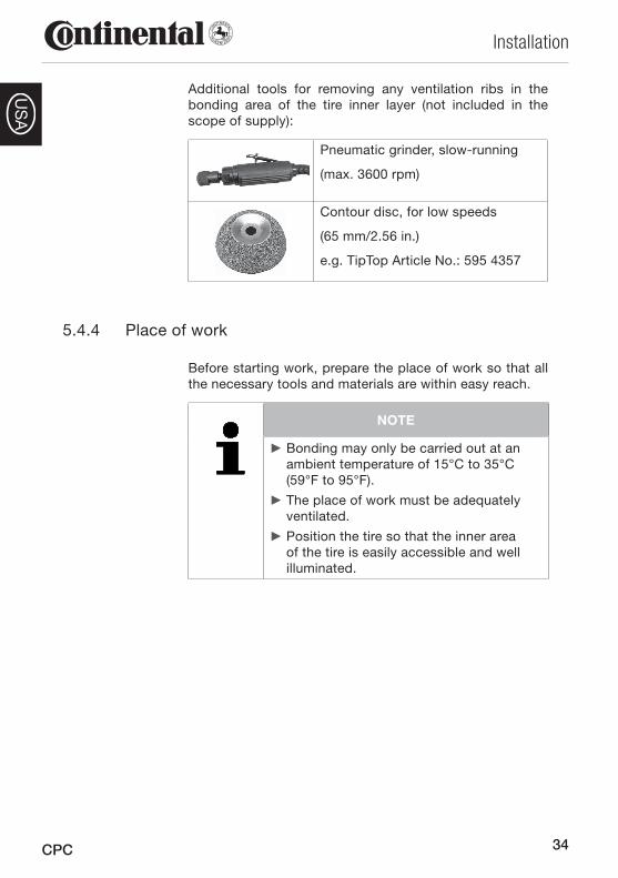
Additional tools for removing any ventilation ribs in the bonding area of the tire inner layer (not included in the scope of supply):
Pneumatic grinder, slow-running
(max. 3600 rpm)
Contour disc, for low speeds
(65 mm/2.56 in.)
e.g. TipTop Article No.: 595 4357
Place of work5.4.4
Before starting work, prepare the place of work so that all the necessary tools and materials are within easy reach.
NOTE
Bonding may only be carried out at an ►ambient temperature of 15°C to 35°C (59°F to 95°F).
The place of work must be adequately ►ventilated.
Position the tire so that the inner area ►of the tire is easily accessible and well illuminated.
35
Installation
CPC
US
A
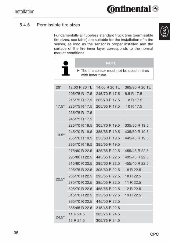
5.4.5 Permissible tire sizes
Fundamentally all tubeless standard truck tires (permissible tire sizes, see table) are suitable for the installation of a tire sensor, as long as the sensor is proper installed and the surface of the tire inner layer corresponds to the normal market conditions.
NOTE
The tire sensor must not be used in tires ►with inner tube.
20“ 12.00 R 20 TL 14.00 R 20 TL 365/80 R 20 TL
17.5“
205/75 R 17.5 245/70 R 17.5 8.5 R 17.5
215/75 R 17.5 265/70 R 17.5 8 R 17.5
225/75 R 17.5 205/65 R 17.5 10 R 17.5
235/75 R 17.5
245/75 R 17.5
19.5“
225/70 R 19.5 305/70 R 19.5 335/50 R 19.5
245/70 R 19.5 385/65 R 19.5 435/50 R 19.5
265/70 R 19.5 255/60 R 19.5 445/45 R 19.5
285/70 R 19.5 385/55 R 19.5
22.5“
275/80 R 22.5 425/65 R 22.5 455/45 R 22.5
295/80 R 22.5 445/65 R 22.5 495/45 R 22.5
315/80 R 22.5 295/60 R 22.5 455/40 R 22.5
295/75 R 22.5 305/60 R 22.5 9 R 22.5
255/70 R 22.5 295/55 R 22.5. 10 R 22.5
275/70 R 22.5 385/55 R 22.5 11 R 22.5
305/70 R 22.5 455/55 R 22.5 12 R 22.5
315/70 R 22.5 355/50 R 22.5 13 R 22.5
365/70 R 22.5 445/50 R 22.5
385/65 R 22.5 315/45 R 22.5
24.5“11 R 24.5 285/75 R 24.5
12 R 24.5 305/75 R 24.5
36
Installation
CPC
US
A
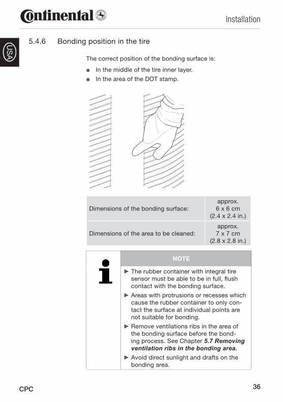
5.4.6 Bonding position in the tire
The correct position of the bonding surface is:
In the middle of the tire inner layer. ■In the area of the DOT stamp. ■
Dimensions of the bonding surface:approx. 6 x 6 cm
(2.4 x 2.4 in.)
Dimensions of the area to be cleaned:approx. 7 x 7 cm
(2.8 x 2.8 in.)
NOTE
The rubber container with integral tire ►sensor must be able to be in full, flush contact with the bonding surface.
Areas with protrusions or recesses which ►cause the rubber container to only con-tact the surface at individual points are not suitable for bonding.
Remove ventilations ribs in the area of ►the bonding surface before the bond-ing process. See Chapter 5.7 Removing ventilation ribs in the bonding area.Avoid direct sunlight and drafts on the ►bonding area.
37
Installation
CPC
US
A
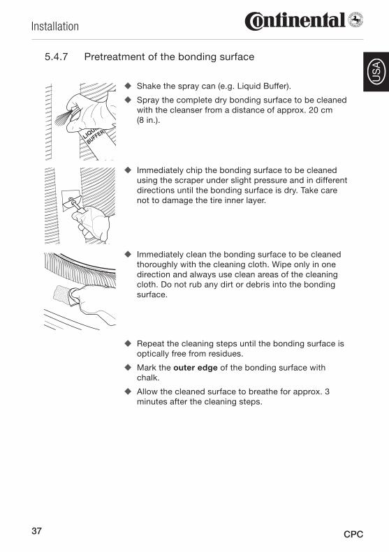
5.4.7 Pretreatment of the bonding surface
Shake the spray can (e.g. Liquid Buffer). �
Spray the complete dry bonding surface to be cleaned �with the cleanser from a distance of approx. 20 cm (8 in.).
Immediately chip the bonding surface to be cleaned �using the scraper under slight pressure and in different directions until the bonding surface is dry. Take care not to damage the tire inner layer.
Immediately clean the bonding surface to be cleaned �thoroughly with the cleaning cloth. Wipe only in one direction and always use clean areas of the cleaning cloth. Do not rub any dirt or debris into the bonding surface.
Repeat the cleaning steps until the bonding surface is �optically free from residues.
Mark the � outer edge of the bonding surface with chalk.
Allow the cleaned surface to breathe for approx. 3 �minutes after the cleaning steps.
38
Installation
CPC
US
A
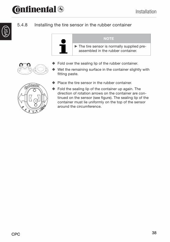
Installing the tire sensor in the rubber container5.4.8
NOTE
The tire sensor is normally supplied pre- ►assembled in the rubber container.
Fold over the sealing lip of the rubber container. �
Wet the remaining surface in the container slightly with �fitting paste.
Place the tire sensor in the rubber container. �
Fold the sealing lip of the container up again. The �direction of rotation arrows on the container are con-tinued on the sensor (see figure). The sealing lip of the container must lie uniformly on the top of the sensor around the circumference.
39
Installation
CPC
US
A
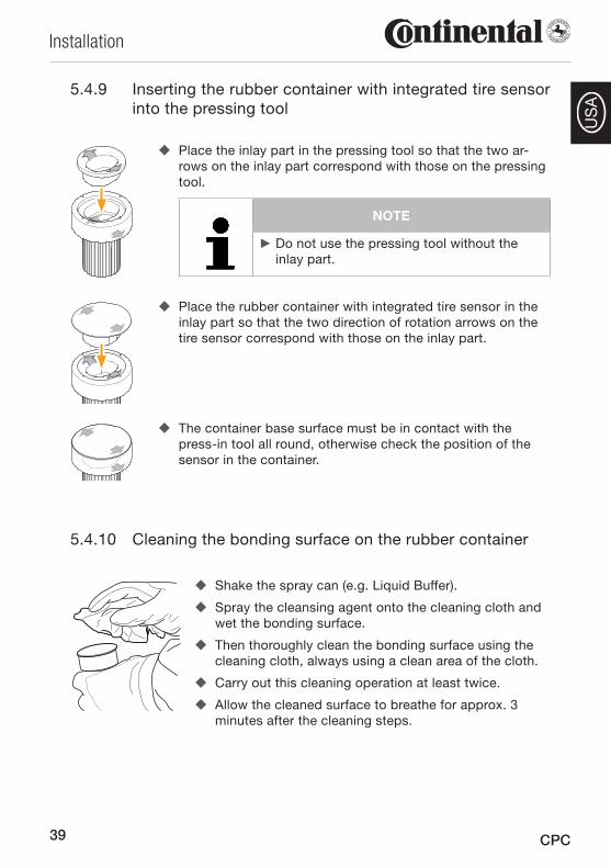
Inserting the rubber container with integrated tire sensor 5.4.9 into the pressing tool
Place the inlay part in the pressing tool so that the two ar- �rows on the inlay part correspond with those on the pressing tool.
NOTE
Do not use the pressing tool without the ►inlay part.
Place the rubber container with integrated tire sensor in the �inlay part so that the two direction of rotation arrows on the tire sensor correspond with those on the inlay part.
The container base surface must be in contact with the �press-in tool all round, otherwise check the position of the sensor in the container.
Cleaning the bonding surface on the rubber container5.4.10
Shake the spray can (e.g. Liquid Buffer). �
Spray the cleansing agent onto the cleaning cloth and �wet the bonding surface.
Then thoroughly clean the bonding surface using the �cleaning cloth, always using a clean area of the cloth.
Carry out this cleaning operation at least twice. �
Allow the cleaned surface to breathe for approx. 3 �minutes after the cleaning steps.
40
Installation
CPC
US
A
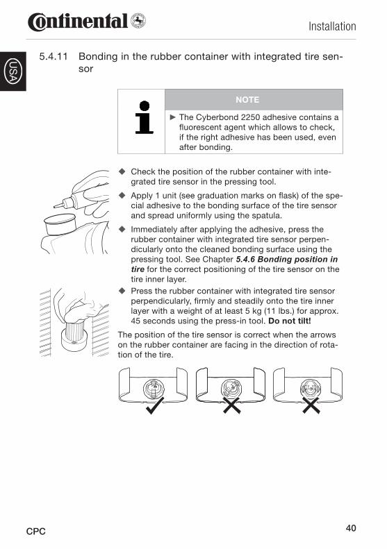
5.4.11 Bonding in the rubber container with integrated tire sen-sor
NOTE
The Cyberbond 2250 adhesive contains a ►fluorescent agent which allows to check, if the right adhesive has been used, even after bonding.
Check the position of the rubber container with inte- �grated tire sensor in the pressing tool.
Apply 1 unit (see graduation marks on flask) of the spe- �cial adhesive to the bonding surface of the tire sensor and spread uniformly using the spatula.
Immediately after applying the adhesive, press the �rubber container with integrated tire sensor perpen-dicularly onto the cleaned bonding surface using the pressing tool. See Chapter 5.4.6 Bonding position in tire for the correct positioning of the tire sensor on the tire inner layer.Press the rubber container with integrated tire sensor �perpendicularly, firmly and steadily onto the tire inner layer with a weight of at least 5 kg (11 lbs.) for approx. 45 seconds using the press-in tool. Do not tilt!
The position of the tire sensor is correct when the arrows on the rubber container are facing in the direction of rota-tion of the tire.
41
Installation
CPC
US
A
5.5 Final inspection of the bonding of the rubber con-tainer
Inspect the bond visually. When bonded correctly, the �rubber container with integral tire sensor is in full, flush contact with the inner layer of the tire.
Carefully wipe away any remaining adhesive around �the edge of the rubber container. Do not pull on the tire sensor or rubber container for (at least) the first 15 minutes.
Before fitting the tire, activate the tire sensor using �the hand-held tool. The tire can then be fitted on the wheel.
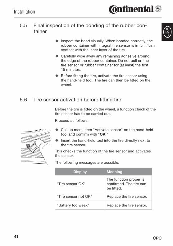
5.6 Tire sensor activation before fitting tire
Before the tire is fitted on the wheel, a function check of the tire sensor has to be carried out.
Proceed as follows:
Call up menu item "Activate sensor" on the hand-held �tool and confirm with "OK.”
Insert the hand-held tool into the tire directly next to �the tire sensor.
This checks the function of the tire sensor and activates the sensor.
The following messages are possible:
Display Meaning
"Tire sensor OK"The function proper is confirmed. The tire can be fitted.
"Tire sensor not OK" Replace the tire sensor.
"Battery too weak" Replace the tire sensor.
42
Installation
CPC
US
A
5.7 Removing ventilation ribs in the bonding area
ATTENTION
Material damage due to damage to the tire inner layer!
Damage to the inner tire layer can cause impairment of the service life of the tire.
Remove only the ventilation ribs. ►Have the work carried out only by per- ►sonnel trained in tire repairs.
Tools required:
Marking pen or chalk ●Goggles, protective gloves ●Slow-running pneumatic grinder ●Brass brush ●65 mm (2.56 in.) contour disc ●Wet/dry vacuum cleaner ●
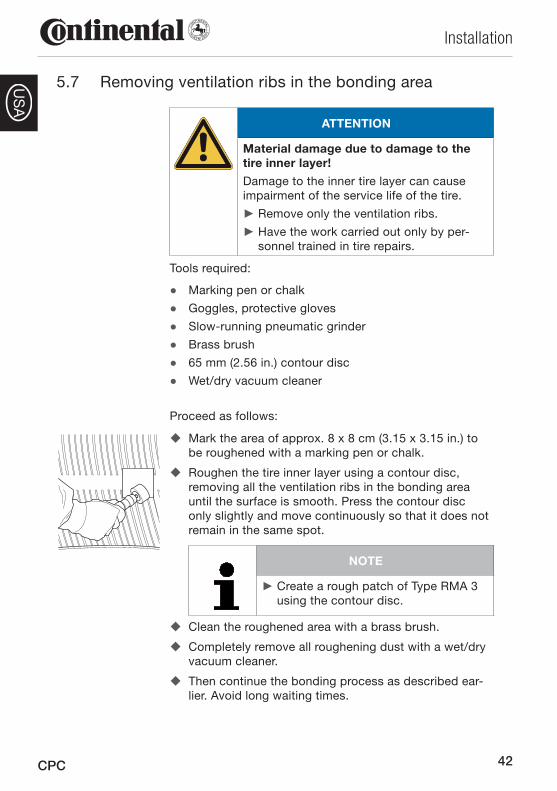
Proceed as follows:
Mark the area of approx. 8 x 8 cm (3.15 x 3.15 in.) to �be roughened with a marking pen or chalk.
Roughen the tire inner layer using a contour disc, �removing all the ventilation ribs in the bonding area until the surface is smooth. Press the contour disc only slightly and move continuously so that it does not remain in the same spot.
NOTE
Create a rough patch of Type RMA 3 ►using the contour disc.
Clean the roughened area with a brass brush. �
Completely remove all roughening dust with a wet/dry �vacuum cleaner.
Then continue the bonding process as described ear- �lier. Avoid long waiting times.
43
Installation
CPC
US
A
5.8 Retreading
Before retreading the tire, remove the tire sensor. The ■rubber container can remain in the tire.
After retreading, install the tire sensor in a new con- ■tainer, see Chapter 5.4.8 Installing the sensors in the rubber container and install in the tire.
NOTE
If no bladder is used during the retread- ►ing process and the process temperature is below 100°C (212°F), the tire sensor can remain in the tire.
Instructions for tire fitting5.8.1
NOTE
In order to be able to better identify the ►position of the tire sensor from the out-side after fitting the tire, position the tire sensor bonded into the tire in the area of the DOT stamp close to the valve seat.
When fitting the tire using tools such as ►tire levers, ensure that these do not dam-age the tire sensor.
5.9 Continued use of the tire sensor after changing a tire
If continuing to use the tire sensor after changing a tire, pay attention to the indicated battery service life and the run-ning life of the sensor indicated in Chapter 3.1 Technical data - Tire sensor.

44
Installation
CPC
US
A
5.10 Use of balancing substances in commercial vehicle tires
Numerous balancing substances from different manufactur-ers are available on the market for filling tubeless truck and bus tires before the fitting process. These are predominant-ly pellets, pastes or liquids and mineral-based substances whose effect (in operation) is intended to eliminate the need for conventional balancing of the wheels.
We neither recommend nor expressly forbid the use of these substances in our tires: Continental Reifen Deutschland GmbH can give no generally applicable comments on the quality and field of application of these substances as they can vary from manufacturer to manufacturer.
The user of such substances should ask the respective manufacturer/dealer about their properties in detail before using them in tires. Ultimately the user has to decide on the method of balancing of commercial vehicles tires and on the use of balancing substances with respect to the spe-cific operating conditions of the tire.
Tire damage and damage to the ContiPressureCheckTM components caused or enhanced by the use of balanc-ing substances is not covered under the ContiPres-sureCheckTM warranty.
Balancing substances should be completely removed from the removed tire before the tire is sent to the incoming in-spection for retreading or repair. We should also point out that we will completely remove any balancing substances in tires sent to us with complaints. Balancing substances removed from the tires will not be returned nor will any re-fund be given.
45
Installation
CPC
US
A
5.11 Installation of the central control unit on HGV/bus
ATTENTION
Damage to the control unit!
When selecting a suitable installation loca-tion, observe the following points to avoid damage to the control unit:
Avoid proximity to sources of high tem- ►peratures (e.g. exhaust system) and to rotating or moving parts.
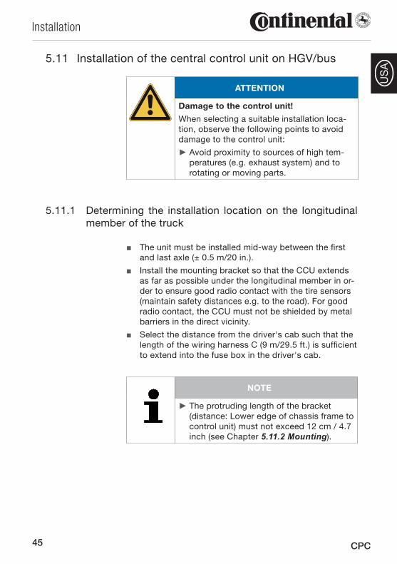
Determining the installation location on the longitudinal 5.11.1 member of the truck
The unit must be installed mid-way between the first ■and last axle (± 0.5 m/20 in.).
Install the mounting bracket so that the CCU extends ■as far as possible under the longitudinal member in or-der to ensure good radio contact with the tire sensors (maintain safety distances e.g. to the road). For good radio contact, the CCU must not be shielded by metal barriers in the direct vicinity.
Select the distance from the driver's cab such that the ■length of the wiring harness C (9 m/29.5 ft.) is sufficient to extend into the fuse box in the driver's cab.
NOTE
The protruding length of the bracket ►(distance: Lower edge of chassis frame to control unit) must not exceed 12 cm / 4.7 inch (see Chapter 5.11.2 Mounting).
46
Installation
CPC
US
A
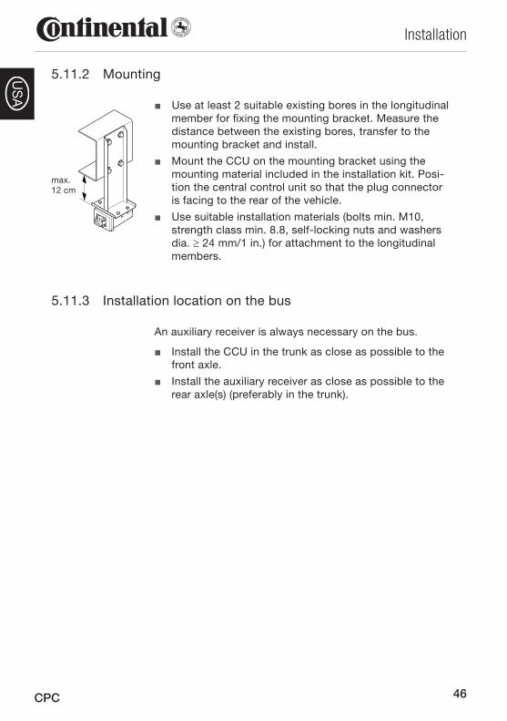
Mounting5.11.2
■ Use at least 2 suitable existing bores in the longitudinal member for fixing the mounting bracket. Measure the distance between the existing bores, transfer to the mounting bracket and install.
Mount the CCU on the mounting bracket using the ■mounting material included in the installation kit. Posi-tion the central control unit so that the plug connector is facing to the rear of the vehicle.
Use suitable installation materials (bolts min. M10, ■strength class min. 8.8, self-locking nuts and washers dia. ≥ 24 mm/1 in.) for attachment to the longitudinal members.
Installation location on the bus5.11.3
An auxiliary receiver is always necessary on the bus.
Install the CCU in the trunk as close as possible to the ■front axle.
Install the auxiliary receiver as close as possible to the ■rear axle(s) (preferably in the trunk).
max.12 cm
47
Installation
CPC
US
A
5.12 Installing an auxiliary receiver (optional)
An auxiliary receiver is necessary to improve the radio con-tact on vehicles with a long wheelbase and on vehicles with more than 2 axles.
NOTE
If an auxiliary receiver is installed, ►install the CCU near the front axle and the auxiliary receiver on the rear of the vehicle.
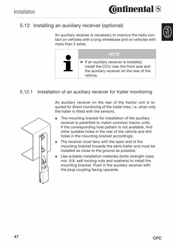
Installation of an auxiliary receiver for trailer monitoring5.12.1
An auxiliary receiver on the rear of the tractor unit is re-quired for direct monitoring of the trailer tires, i.e. when only the trailer is fitted with tire sensors.
■ The mounting bracket for installation of the auxiliary receiver is predrilled to match common tractor units. If the corresponding hole pattern is not available, find other suitable holes in the rear of the vehicle and drill holes in the mounting bracket accordingly.
The receiver must face with the open end of the ■mounting bracket towards the semi-trailer and must be installed as close to the ground as possible.
Use suitable installation materials (bolts strength class ■min. 8.8, self-locking nuts and washers) to install the mounting bracket. Push in the auxiliary receiver with the plug coupling facing upwards.
48
Installation
CPC
US
A
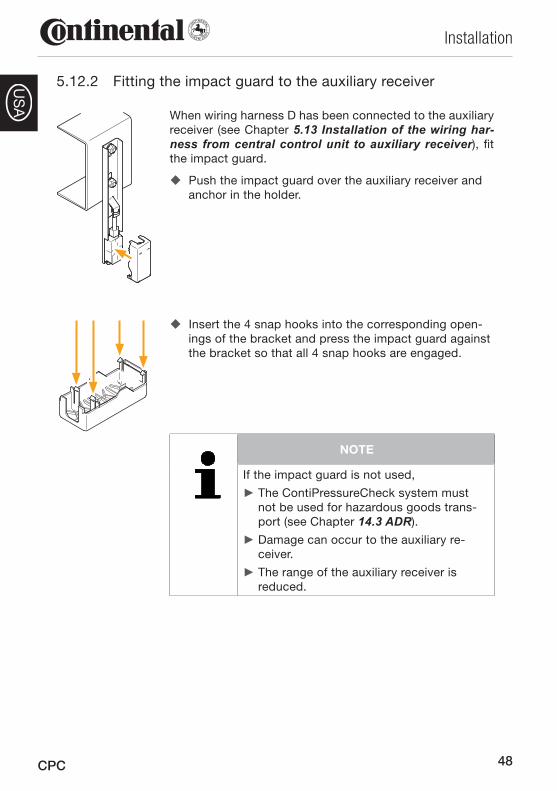
Fitting the impact guard to the auxiliary receiver5.12.2
When wiring harness D has been connected to the auxiliary receiver (see Chapter 5.13 Installation of the wiring har-ness from central control unit to auxiliary receiver), fit the impact guard.
� Push the impact guard over the auxiliary receiver and anchor in the holder.
� Insert the 4 snap hooks into the corresponding open-ings of the bracket and press the impact guard against the bracket so that all 4 snap hooks are engaged.
NOTE
If the impact guard is not used,
The ContiPressureCheck system must ►not be used for hazardous goods trans-port (see Chapter 14.3 ADR).
Damage can occur to the auxiliary re- ►ceiver.
The range of the auxiliary receiver is ►reduced.
49
Installation
CPC
US
A
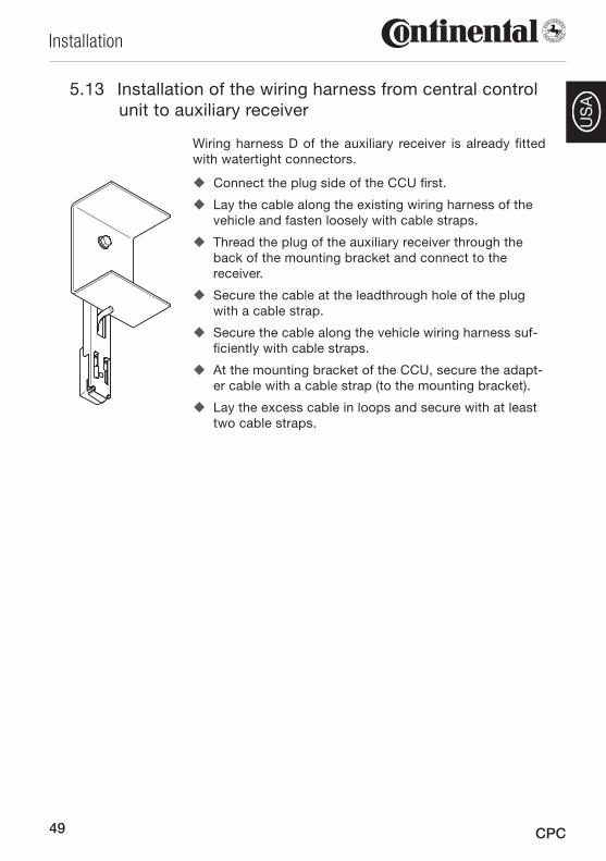
Installation of the wiring harness 5.13 from central control unit to auxiliary receiver
Wiring harness D of the auxiliary receiver is already fitted with watertight connectors.
� Connect the plug side of the CCU first.
Lay the cable along the existing wiring harness of the �vehicle and fasten loosely with cable straps.
Thread the plug of the auxiliary receiver through the �back of the mounting bracket and connect to the receiver.
Secure the cable at the leadthrough hole of the plug �with a cable strap.
Secure the cable along the vehicle wiring harness suf- �ficiently with cable straps.
At the mounting bracket of the CCU, secure the adapt- �er cable with a cable strap (to the mounting bracket).
Lay the excess cable in loops and secure with at least �two cable straps.
50
Installation
CPC
US
A
Installation of the wiring harness 5.14 from central control unit to fuse box
ATTENTION
Damage to the wiring harness!
When laying the wiring harness, observe the following points to avoid damage to the harness:
Avoid proximity to sources of high tem- ►peratures (e.g. exhaust system) and to rotating or moving parts.
Connect the plug end of wiring harness C to the CCU �or to the mating plug of wiring harness D (if used).
From there, lay the cable along the existing wiring �harness of the vehicle to the driver's cab and fasten loosely with cable straps.
Lay the wiring harness to the fuse box of the vehicle �(see also vehicle operating manual).
Finally secure the cable along the vehicle wiring har- �ness with cable straps once again.
51
Installation
CPC
US
A
5.15 Installation of the display
WARNING
Risk of injury!
The risk of injury cannot be ruled out if the installation instructions are not followed.
Attach the display to the windshield ►offset to the side from the driver and passenger(s).
Do not install the display in the body, ►head or airbag area (driver & passengers).
Place the display into the bracket supplied, paying at- �tention to complete engagement.
Determine a suitable installation location on the �windshield. Pay attention to possible interference from sunlight.
NOTE
The vehicle driver must have a sufficient field of view under all operating and weather conditions.
Install the display as low as possible ►so that the driver's field of view is not obstructed.
52
Installation
CPC
US
A
Installation of the wiring harness 5.16 from display to fuse box
ATTENTION
Danger of short-circuit!
Switch off the ignition before starting ►work.
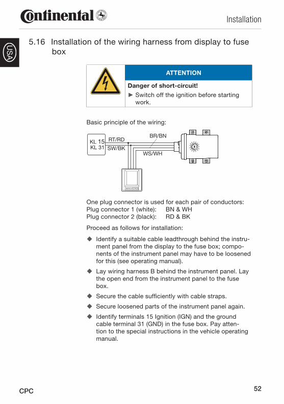
Basic principle of the wiring:
KL 15KL 31
RT/RD
SW/BK
BR/BN
WS/WH
One plug connector is used for each pair of conductors: Plug connector 1 (white): BN & WH Plug connector 2 (black): RD & BK
Proceed as follows for installation:
Identify a suitable cable leadthrough behind the instru- �ment panel from the display to the fuse box; compo-nents of the instrument panel may have to be loosened for this (see operating manual).
Lay wiring harness B behind the instrument panel. Lay �the open end from the instrument panel to the fuse box.
Secure the cable sufficiently with cable straps. �
Secure loosened parts of the instrument panel again. �
Identify terminals 15 Ignition (IGN) and the ground �cable terminal 31 (GND) in the fuse box. Pay atten-tion to the special instructions in the vehicle operating manual.
53
Installation
CPC
US
A
Lay wiring harness A to cables B and C, starting from �the fuse box. The integrated fuse remains in the wiring harness.
ATTENTION
Danger of short-circuit!
Risk of short-circuit if the fuse is not installed.
Do not shorten the supply line A on the ►fuse side.
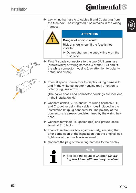
� First fit spade connectors to the two CAN terminals (brown/white) of wiring harness C of the CCU and fit the white connector housing (pay attention to polarity notch, see arrow).
� Then fit spade connectors to display wiring harness B and fit the white connector housing (pay attention to polarity lug, see arrow).
(The cable shoes and connector housings are included in the installation kit.)
Connect cables KL 15 and 31 of wiring harness A, B �and C together using the cable shoes included in the installation kit (plug connector 2). The polarity of the connectors is already predetermined by the wiring har-ness.
Connect terminals 15 Ignition (red) and ground cable �terminal 31 (black).
Then close the fuse box again securely, ensuring that �after completion of the installation that the original leak tightness of the fuse box is retained.
Connect the plug of the wiring harness to the display. �
NOTE
See also the figure in Chapter ► 4.8 Wir-ing truck/bus with auxiliary receiver.
54
Installation
CPC
US
A
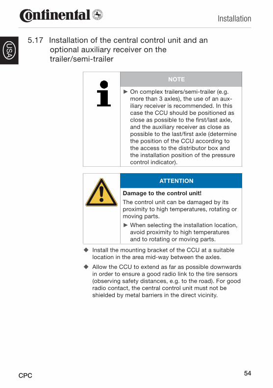
5.17 Installation of the central control unit and an optional auxiliary receiver on the trailer/semi-trailer
NOTE
On complex trailers/semi-trailer (e.g. ►more than 3 axles), the use of an aux-iliary receiver is recommended. In this case the CCU should be positioned as close as possible to the first/last axle, and the auxiliary receiver as close as possible to the last/first axle (determine the position of the CCU according to the access to the distributor box and the installation position of the pressure control indicator).
ATTENTION
Damage to the control unit!
The control unit can be damaged by its proximity to high temperatures, rotating or moving parts.
When selecting the installation location, ►avoid proximity to high temperatures and to rotating or moving parts.
Install the mounting bracket of the CCU at a suitable �location in the area mid-way between the axles.
Allow the CCU to extend as far as possible downwards �in order to ensure a good radio link to the tire sensors (observing safety distances, e.g. to the road). For good radio contact, the central control unit must not be shielded by metal barriers in the direct vicinity.
55
Installation
CPC
US
A
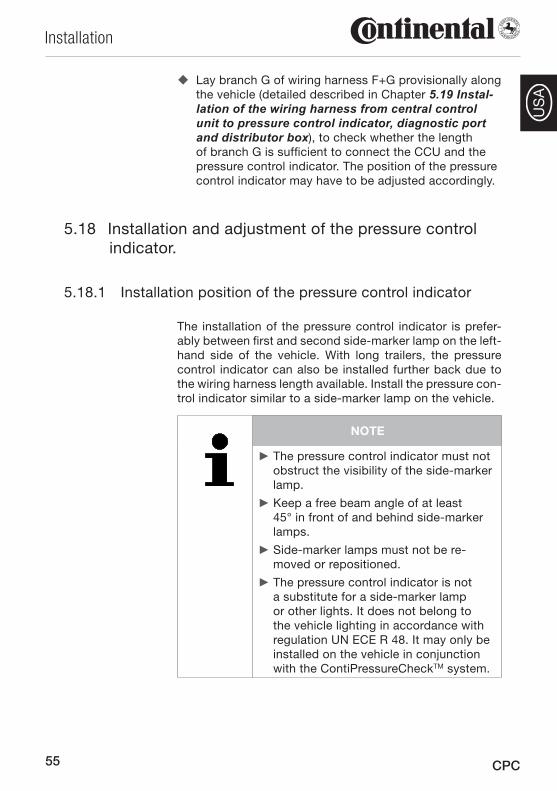
Lay branch G of wiring harness F+G provisionally along �the vehicle (detailed described in Chapter 5.19 Instal-lation of the wiring harness from central control unit to pressure control indicator, diagnostic port and distributor box), to check whether the length of branch G is sufficient to connect the CCU and the pressure control indicator. The position of the pressure control indicator may have to be adjusted accordingly.
Installation and adjustment of the pressure control 5.18 indicator.
5.18.1 Installation position of the pressure control indicator
The installation of the pressure control indicator is prefer-ably between first and second side-marker lamp on the left-hand side of the vehicle. With long trailers, the pressure control indicator can also be installed further back due to the wiring harness length available. Install the pressure con-trol indicator similar to a side-marker lamp on the vehicle.
NOTE
The pressure control indicator must not ►obstruct the visibility of the side-marker lamp.
Keep a free beam angle of at least ►45° in front of and behind side-marker lamps.
Side-marker lamps must not be re- ►moved or repositioned.
The pressure control indicator is not ►a substitute for a side-marker lamp or other lights. It does not belong to the vehicle lighting in accordance with regulation UN ECE R 48. It may only be installed on the vehicle in conjunction with the ContiPressureCheckTM system.
56
Installation
CPC
US
A
ATTENTION
Damage to the pressure control indica-tor!
Risk of damage if the pressure control indicator is installed in the marked area for crane loading.
Do not use the marked area if the ve- ►hicle is loaded by crane.
ATTENTION
Damage to the pressure control indica-tor!
If the pressure control indicator is installed on vehicle with dropsides there is a risk of damage to the bracket of the pressure control indicator by the falling tailgate. The rubber arm of the pressure control indicator may be deformed by the falling dropside. The deflection movement of the rubber arm should not be obstructed by unevenness and projecting parts on the dropside.
Position the bracket of the pressure ►control indicator accordingly and check the deformation of the rubber arm.
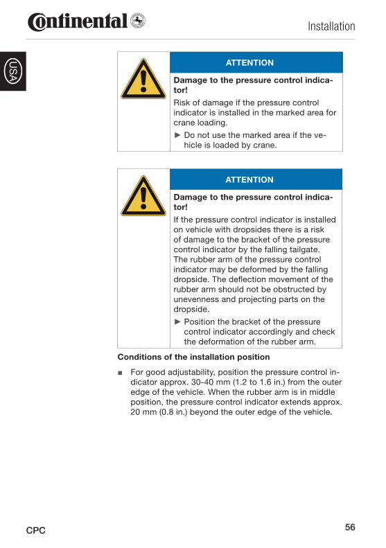
Conditions of the installation position
For good adjustability, position the pressure control in- ■dicator approx. 30-40 mm (1.2 to 1.6 in.) from the outer edge of the vehicle. When the rubber arm is in middle position, the pressure control indicator extends approx. 20 mm (0.8 in.) beyond the outer edge of the vehicle.
57
Installation
CPC
US
A1
23
4
30 - 40 mm1.2 to 1.6 in.
approx. 20 mm 0.8 in.
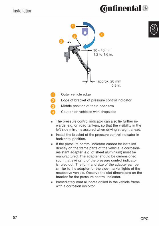
1 Outer vehicle edge
2 Edge of bracket of pressure control indicator
3 Middle position of the rubber arm
4 Caution on vehicles with dropsides
The pressure control indicator can also lie further in- ■wards, e.g. on road tankers, so that the visibility in the left side mirror is assured when driving straight ahead.
Install the bracket of the pressure control indicator in ■horizontal position.
If the pressure control indicator cannot be installed ■directly on the frame parts of the vehicle, a corrosion-resistant adapter (e.g. of sheet aluminium) must be manufactured. The adapter should be dimensioned such that swinging of the pressure control indicator is ruled out. The form and size of the adapter can be similar to the adapter for the side-marker lights of the respective vehicle. Observe the slot dimensions on the bracket for the pressure control indicator.
Immediately coat all bores drilled in the vehicle frame ■with a corrosion inhibitor.
58
Installation
CPC
US
A
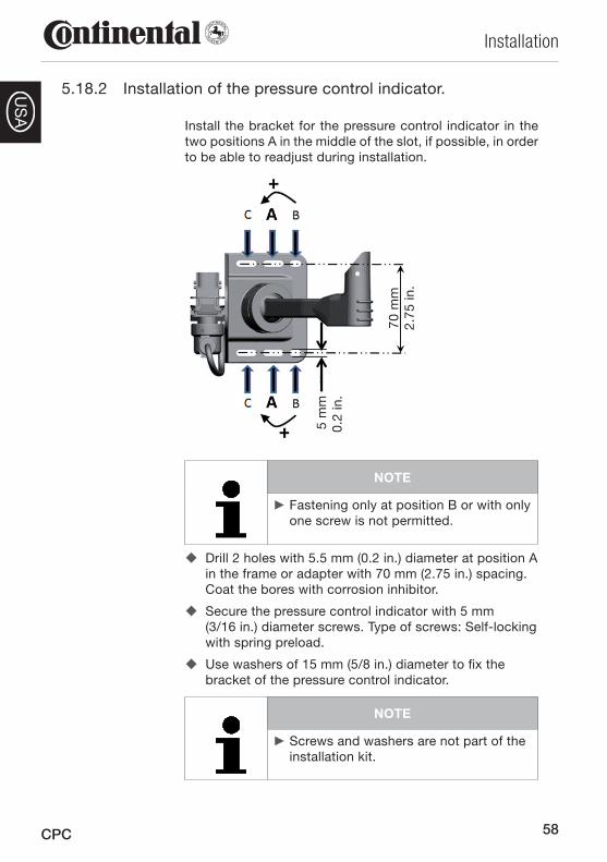
5.18.2 Installation of the pressure control indicator.
Install the bracket for the pressure control indicator in the two positions A in the middle of the slot, if possible, in order to be able to readjust during installation.
70 m
m
2.75
in.
5 m
m
0.2
in.
NOTE
Fastening only at position B or with only ►one screw is not permitted.
Drill 2 holes with 5.5 mm (0.2 in.) diameter at position A �in the frame or adapter with 70 mm (2.75 in.) spacing. Coat the bores with corrosion inhibitor.
Secure the pressure control indicator with 5 mm �(3/16 in.) diameter screws. Type of screws: Self-locking with spring preload.
Use washers of 15 mm (5/8 in.) diameter to fix the �bracket of the pressure control indicator.
NOTE
Screws and washers are not part of the ►installation kit.
59
Installation
CPC
US
A
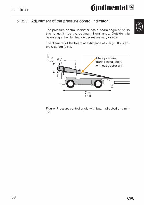
5.18.3 Adjustment of the pressure control indicator.
The pressure control indicator has a beam angle of 5°. In this range it has the optimum illuminance. Outside this beam angle the illuminance decreases very rapidly.
The diameter of the beam at a distance of 7 m (23 ft.) is ap-prox. 60 cm (2 ft.).
60 c
m2
ft.
5°Mark position, during installation without tractor unit
7 m 23 ft.
Figure: Pressure control angle with beam directed at a mir-ror.
60
Installation
CPC
US
A
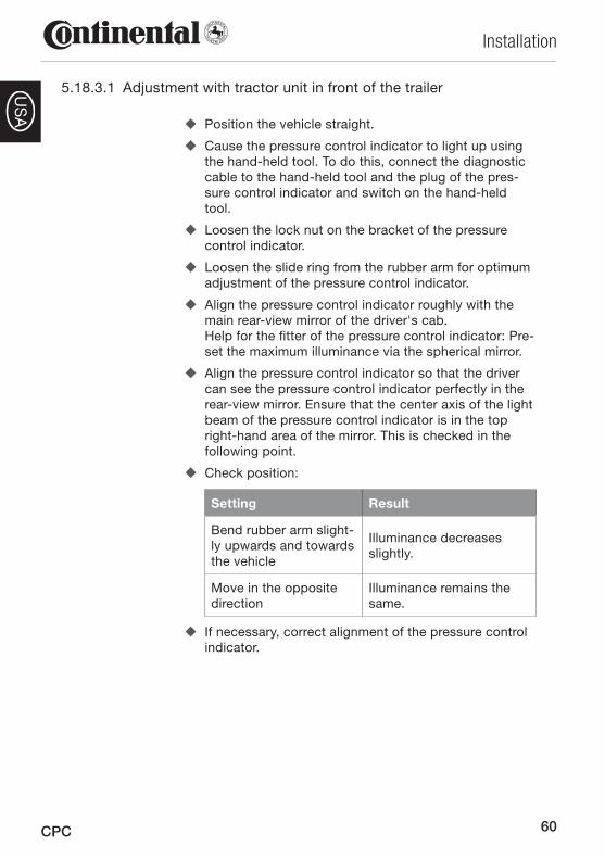
Adjustment with tractor unit in front of the trailer5.18.3.1
Position the vehicle straight. �
Cause the pressure control indicator to light up using �the hand-held tool. To do this, connect the diagnostic cable to the hand-held tool and the plug of the pres-sure control indicator and switch on the hand-held tool.
Loosen the lock nut on the bracket of the pressure �control indicator.
Loosen the slide ring from the rubber arm for optimum �adjustment of the pressure control indicator.
Align the pressure control indicator roughly with the �main rear-view mirror of the driver's cab. Help for the fitter of the pressure control indicator: Pre-set the maximum illuminance via the spherical mirror.
Align the pressure control indicator so that the driver �can see the pressure control indicator perfectly in the rear-view mirror. Ensure that the center axis of the light beam of the pressure control indicator is in the top right-hand area of the mirror. This is checked in the following point.
Check position: �
Setting Result
Bend rubber arm slight-ly upwards and towards the vehicle
Illuminance decreases slightly.
Move in the opposite direction
Illuminance remains the same.
If necessary, correct alignment of the pressure control �indicator.
61
Installation
CPC
US
A
Tighten lock nut finger-tight (2 Nm), so that the ball �joint of the rubber arm can no longer move within the mounting.
NOTE
The material becomes more rigid at low ►temperatures.
At temperatures below 2°C (35.6°F) the ►tightening torque should not exceed 2 Nm, otherwise there is a risk of dam-age.
At higher temperature, check and adjust ►the tightening torque accordingly.
Check the visibility of the pressure control indica- �tor during the test drive and "Teach-in of ContiPres-sureCheckTM.” If necessary, correct alignment.
Prealignment of the pressure control indicator on the trailer 5.18.3.2 without tractor unit
Before uncoupling the tractor unit, determine the posi- �tion of the pressure control indicator on the trailer.
By surveying from this position, mark the upper edge �of the main mirror on the corner of the trailer.
Switch on the installed pressure control indicator and �align roughly with the mark.
Check the pressure control indicator from the marked �point on the trailer. Movement of the head from the marked position on the trailer:
Movement Result
approx. 20-30 cm (1 ft.) right
Illuminance decreases slightly.
approx. 20-30 cm (1 ft.) down
Illuminance decreases slightly.
approx. 20-30 cm (1 ft.) up
Illuminance remains the same.
62
Installation
CPC
US
A
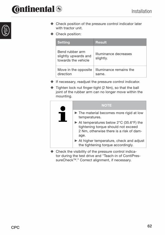
Check position of the pressure control indicator later �with tractor unit.
Check position: �
Setting Result
Bend rubber arm slightly upwards and towards the vehicle
Illuminance decreases slightly.
Move in the opposite direction
Illuminance remains the same.
If necessary, readjust the pressure control indicator. �
Tighten lock nut finger-tight (2 Nm), so that the ball �joint of the rubber arm can no longer move within the mounting.
NOTE
The material becomes more rigid at low ►temperatures.
At temperatures below 2°C (35.6°F) the ►tightening torque should not exceed 2 Nm, otherwise there is a risk of dam-age.
At higher temperature, check and adjust ►the tightening torque accordingly.
Check the visibility of the pressure control indica- �tor during the test drive and "Teach-in of ContiPres-sureCheckTM.” Correct alignment, if necessary.
63
Installation
CPC
US
A
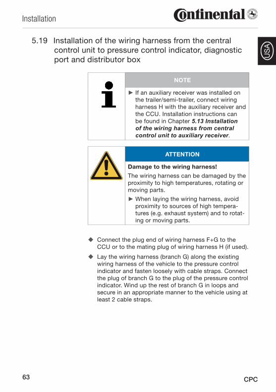
Installation of the wiring harness 5.19 from the central control unit to pressure control indicator, diagnostic port and distributor box
NOTE
If an auxiliary receiver was installed on ►the trailer/semi-trailer, connect wiring harness H with the auxiliary receiver and the CCU. Installation instructions can be found in Chapter 5.13 Installation of the wiring harness from central control unit to auxiliary receiver.
ATTENTION
Damage to the wiring harness!
The wiring harness can be damaged by the proximity to high temperatures, rotating or moving parts.
When laying the wiring harness, avoid ►proximity to sources of high tempera-tures (e.g. exhaust system) and to rotat-ing or moving parts.
Connect the plug end of wiring harness F+G to the �CCU or to the mating plug of wiring harness H (if used).
Lay the wiring harness (branch G) along the existing �wiring harness of the vehicle to the pressure control indicator and fasten loosely with cable straps. Connect the plug of branch G to the plug of the pressure control indicator. Wind up the rest of branch G in loops and secure in an appropriate manner to the vehicle using at least 2 cable straps.
64
Installation
CPC
US
A
Lay branch F from the CCU along the existing wiring �harness to the distributor box or to the vehicle power supply and fasten loosely with cable straps.
Find a suitable cable leadthrough in the distributor box �and thread in the cable.
Shorten branch F, if necessary, to the required length. �
In the distributor box, fasten the fuse supplied to the �plus cable (red) using the cable shoes in the installation kit.
In the distributor box, identify terminals U_bat and �GND. Pay attention to the special instructions in the vehicle operating manual.
Connect the red cable in branch F (incl. fuse) to termi- �nal U_bat and the black cable to terminal GND.
Then close the distributor box again securely, ensuring �that after completion of the installation that the original leak tightness of the distributor box is retained.
Finally secure branches F and G along the vehicle wir- �ing harness with cable straps once again.
Checks after installation5.20
After completing installation, check all systems of the �vehicle (e.g. brake and lighting system) for proper func-tion.
65
Initialization using hand-held tool
CPC
US
A6 Initialization using hand-held toolFor initialization using the hand-held tool, proceed as fol-lows:
Switch on the hand-held tool. �
Select menu item Installation / New installation. �
Follow the instructions on the hand-held tool. �
NOTE
When setting the nominal pressure for ►the individual axes, pay attention to the tire manufacturers' instructions.
On completion of the inputs, the vehicle configuration is displayed on the display of the hand-held tool.
Confirm the vehicle configuration or select a different �configuration.
The latest list of vehicle configurations approved for �installation can be found at www.contipressurecheck.com. Should this list not correspond to the vehicle configuration stored in the hand-held tool, update the software of the hand-held tool (Details on updating the software of the hand-held tool see manual of the hand-held tool).
NOTE
The vehicle operator must ensure that ►the CPC system is correctly installed and acivated. This includes setting the nominal pressures recommended in the tire guide, correct assignment of the tire sensors to the wheel position, etc.
66
Initialization using hand-held tool
CPC
US
A
Confirmation of the vehicle configuration is followed by the teach-in of the tire sensors. The tire position to be read out is displayed on the hand-held tool.
NOTE
The first axle is shown on the left-hand ►side of the hand-held tool display, the last axle on the right-hand side.
Hold the hand-held tool in the wheel position shown �and against the side wall and follow the animation on the display.
NOTE
The hand-held tool can remain on the ►outer of the twin tires when reading out the tire sensor of the inner tire.
After reading out the last tire sensor, connect the hand- �held tool via the diagnostic cable as follows:
On truck and bus, to the diagnostic plug of the -display
On the trailer, to the diagnostic plug of the pressure -control indicator
Follow the instructions on the hand-held tool (the con- �trol unit is configured).
67
Initialization using hand-held tool
CPC
US
A
After successful configuration, switch off the control �unit for at least 30 seconds. To do this, switch off the ignition or turn off the battery main switch if the control unit on the trailer has been connected to a permanent power supply. Then continue with Chapter 7 Test drive for system testing.
NOTE
If ATL* (automatic trailer detection) was ►selected, only one nominal pressure can be set for all the tires on the trailer.
* ATL is an optional function and is not activated on all CPC systems.
During later operation:
NOTE
After replacing or changing the posi- ►tion of one or more tire sensors, reset the telegram counter in the display, see Chapter 11.1 Diagnostics via display - Reset telegram counter.
68
Test Drive for System Testing
CPC
US
A
7 Test Drive for System Testing
Test drive for system testing on the 7.1 HGV/bus
To test the whole system, carry out a test drive as follows:
Connect the hand-held tool to the display and select �menu item "Installation / Test drive truck/bus.”
Start test drive. �
NOTE
A progress bar is displayed on the ►screen during the test drive.
The test drive can be aborted at any ►time by holding the ESC key pressed for at least 3 seconds.
Should one of the following warnings ►appear on the display during the test drive: VERY LOW PRESSURE. PRESSURE LOSS SENSOR DEFECTIVE TEST SENSOR abort the test drive, remedy the fault and repeat the test drive.
At speeds above 30 km/h (18.6 mph), ►the test drive is normally completed after 5 minutes.
After the start of the menu, the display on the hand-held tool changes to the bird's eye perspective, the left-hand side shows the first axle of the vehicle.
The transmission power of the tire sensors (RSSI) or the number of telegrams received is shown in the tire symbols.
NOTE
Switch between the two displays (RSSI ►and number of telegrams) with the arrow keys left and right.
69
Test Drive for System Testing
CPC
US
A
At the end of the test drive, the following is displayed on the hand-held tool:
Display Meaning
Reception OK Test drive was successful.
Poor reception
Test drive was not successful. Wheel positions with inad-equate reception are indicated by a flashing display.
Failed
Test drive was not successful (number of radio signals too low). The corresponding wheel positions are indicated by a flashing display.
NOTE
Truck and trailer
After a successful test drive, the results ►are automatically saved. If there are no data in the hand-held tool, the input of a registration number or vehicle serial number is prompted.
If the test drive is not completed successfully, correct the position of the CCU.
Adjust the CCU closer to the wheel position indicated �by the flashing display.
Position the CCU lower by loosening the mounting �bracket and moving the unit closer to the road.
On vehicles with a very long wheelbase, continue with Chapter 5.12 Installation of an auxiliary receiver.
After the test drive, finally read out the error messages (Diagnostic Trouble Codes: DTCs).
If there are active DTCs: Remedy the fault (see at -www.contipressurecheck.com) and repeat the test.
If there are passive DTCs: Erase all DTCs. -
70
Test Drive for System Testing
CPC
US
A
Test drive for system testing on the 7.2 semi-trailer
Preparation for the test drive:
Disconnect the plug of wiring harness F+G (branch G) �from the pressure control indicator.
Connect the hand-held tool to branch G via the diag- �nostic cable and select menu item "Installation / Test drive trailer / Initialization.”
When the operation has been successfully completed:
Disconnect the hand-held tool. �
Connect branch G to the pressure control indicator. �
Carry out the test drive without the hand-held tool. �
NOTE
At speeds above 30 km/h (18.6 mph), the test drive is normally completed after 5 minutes.
The test drive is completed when the pressure control indi-cator lights up for 60 seconds.
Connect the hand-held tool to branch G again and se- �lect menu item "Installation / Test drive trailer / Evalu-ation.”
For the display on the hand-held tool and for working in-structions, see Chapter 7.1 Test drive for system testing on the truck.
After the test drive, finally read out the error messages (Diagnostic Trouble Codes: DTCs).
If there are active DTCs: Remedy the fault (see at -www.contipressurecheck.com) and repeat the test.
If there are passive DTCs: Erase all DTCs. -
Finally switch off the hand-held tool and disconnect it �from branch G.
Connect branch G to the pressure control indicator. �

71
Test Drive for System Testing
CPC
US
A
Preparation for repeating a test drive7.3
If a test drive has to be repeated, e.g. after repositioning of the mounting bracket of the CCU, all the tire sensors have to be reset to Park mode (MP) before the start of the test drive.
The menu "Prepar. additional test drive" shows the aerial view of the vehicle.
The corresponding wheel position is displayed on the hand-held tool.
NOTE
The first axle is shown on the left-hand ►side of the hand-held tool display, the last axle on the right-hand side.
Hold the hand-held tool in the wheel position shown �and against the side wall and follow the animation on the display.
NOTE
The hand-held tool can remain on the ►outer of the twin tires when resetting the tire sensor of the inner tire to Park mode.
When all the tire sensors have been reset to Park mode, the hand-held tool displays "Vehicle ready for next test drive.”
Continue with Chapter � 7 Test drive for system test-ing.
72
Modification of the CPC system configuration
CPC
US
A
8 Modification of the CPC system configurationIf changes are made later to the CPC system installation, the configuration of the CCU has to be modified with the hand-held tool.
8.1 Automatic wheel change detection (optional func-tion)*
If, during operation, a single tire with tire sensor is replaced, the CPC system detects this automatically. Reconfiguration with the hand-held tool is not necessary.
The new tire sensor is generally detected automatically ■during the first drive after the tire change.
This process is completed after approx. 10 minutes' ■driving time.
During the teach-in process, no pressure value is dis- ■played in the corresponding tire symbol.
NOTE
If the detection fails during the first drive, ►the message "NO RECEPTION" appears on the display for this tire position and the pressure control indicator flashes slowly. When the ignition is switched on again, the detection should function suc-cessfully.
* Automatic tire change detection is an optional function and is not acti-vated in all CPC systems.
73
Documentation of system installation
CPC
US
A
Manual adaptations with the hand-held tool8.2
A reconfiguration of the CPC system is necessary and pos-sible in the following cases:
Switching the auxiliary receiver on/off ■Changing the status of an axle (lift axle yes/no) ■Changing the nominal pressure for an axle ■Changing the position of the tire sensors ■Replacement of at least 2 tire sensors (new tire sen- ■sors)
To do this, call up the following menus on the hand-held tool and follow the instructions on the hand-held tool:
"Modification - Modify/check installation - Modify CCU ●parameters"
"Modification - Modify/check installation - Modify sen- ●sor IDs"
If the changes exceed the scope described above, a re-initialization is necessary as described in Chapter 6 Initiali-zation via hand-held tool.
9 Documentation of system installationAfter successful installation, the vehicle configuration must be transmitted to a computer and printed out for documen-tation purposes.
This document contains all the tire IDs, the vehicle configu-ration, the installed components and the result of the test drive (RSSI and number of telegrams).
This document must be signed by the installer and the garage manager/supervisor.
A copy must be placed in the vehicle.
74
Information on the system
CPC
US
A
Information on the system10
General10.1
ContiPressureCheck ■ TM provides assistance in monitor-ing tire pressures. The responsibility for the correct tire pressure lies with the driver.
Correct the tire pressure only when the tire temperature ■corresponds to the ambient temperature.
Operation10.2
During operation of the system, carry out the following measures:
Clean the light surface of the pressure control indicator ■at regular intervals.
The driver must ensure that the pressure control indi- ■cator can be seen in the rear-view mirror. For this, the pressure control indicator lights up for 10 seconds at each vehicle start.
Keep the CCU and the auxiliary receiver free of dirt ■and debris, e.g. snow and sludge, so that the reception power is not impaired.
11 DiagnosticsA diagnostic guide (incl. the diagnostic function of the hand-held tool) and corresponding working instructions can be found at www.contipressurecheck.com.
This chapter deals with the diagnostic instructions and di-agnostic possibilities of the display.
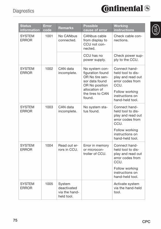
75
Diagnostics
CPC
US
AStatus information
Error code
RemarksPossible cause of error
Working instructions
SYSTEM ERROR
1001 No CANbus connected.
CANbus cable from display to CCU not con-nected.
Check cable con-nections.
CCU has no power supply.
Check power sup-ply to the CCU.
SYSTEM ERROR
1002 CAN data incomplete.
No system con-figuration found OR No tire sen-sor data found OR No position allocation of the tires to CAN found.
Connect hand-held tool to dis-play and read out error codes from CCU.
Follow working instructions on hand-held tool.
SYSTEM ERROR
1003 CAN data incomplete.
No system sta-tus found.
Connect hand-held tool to dis-play and read out error codes from CCU.
Follow working instructions on hand-held tool.
SYSTEM ERROR
1004 Read out er-rors in CCU.
Error in memory or microcon-troller of CCU.
Connect hand-held tool to dis-play and read out error codes from CCU.
Follow working instructions on hand-held tool.
SYSTEM ERROR
1005 System deactivated via the hand-held tool.
Activate system via the hand-held tool.
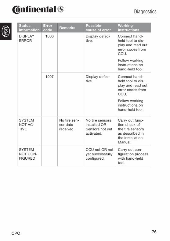
76
Diagnostics
CPC
US
A
Status information
Error code
RemarksPossible cause of error
Working instructions
DISPLAY ERROR
1006 Display defec-tive.
Connect hand-held tool to dis-play and read out error codes from CCU.
Follow working instructions on hand-held tool.
1007 Display defec-tive.
Connect hand-held tool to dis-play and read out error codes from CCU.
Follow working instructions on hand-held tool.
SYSTEM NOT AC-TIVE
No tire sen-sor data received.
No tire sensors installed OR Sensors not yet activated.
Carry out func-tion check of the tire sensors as described in the Installation Manual.
SYSTEM NOT CON-FIGURED
CCU not OR not yet successfully configured.
Carry out con-figuration process with hand-held tool.
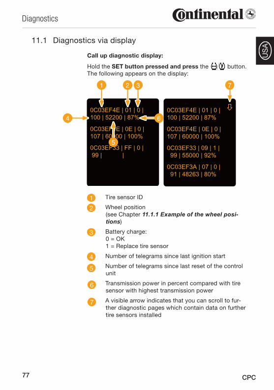
77
Diagnostics
CPC
US
A
11.1 Diagnostics via display
Call up diagnostic display:
Hold the SET button pressed and press the button. The following appears on the display:
0C03EF4E | 01 | 0 |100 | 52200 | 87%
0C03EF4E | 0E | 0 |107 | 60000 | 100%
0C03EF33 | 09 | 1 | 99 | 55000 | 92%
0C03EF3A | 07 | 0 | 91 | 48263 | 80%
0C03EF4E | 01 | 0 |100 | 52200 | 87%
0C03EF4E | 0E | 0 |107 | 60000 | 100%
0C03EF33 | FF | 0 | 99 | |
1 2 3
4
5
6
7
1 Tire sensor ID
2 Wheel position (see Chapter 11.1.1 Example of the wheel posi-tions)
3 Battery charge: 0 = OK 1 = Replace tire sensor
4 Number of telegrams since last ignition start
5 Number of telegrams since last reset of the control unit
6 Transmission power in percent compared with tire sensor with highest transmission power
7 A visible arrow indicates that you can scroll to fur-ther diagnostic pages which contain data on further tire sensors installed
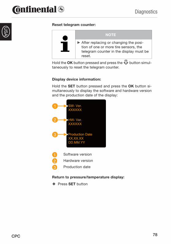
78
Diagnostics
CPC
US
A
Reset telegram counter:
NOTE
After replacing or changing the posi- ►tion of one or more tire sensors, the telegram counter in the display must be reset.
Hold the OK button pressed and press the button simul-taneously to reset the telegram counter.
Display device information:
Hold the SET button pressed and press the OK button si-multaneously to display the software and hardware version and the production date of the display:
SW- Ver.XXXXXX
HW- Ver.XXXXXX
Production DateXX.XX.XXDD.MM.YY
1
2
3
1 Software version
2 Hardware version
3 Production date
Return to pressure/temperature display:
Press � SET button
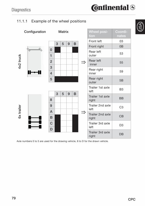
79
Diagnostics
CPC
US
A
Example of the wheel positions11.1.1
Configuration Matrix Wheel posi-tion
Coordi-nates
4x2
truc
k
3 5 9 B
0
1
2
3
4
5
⇒
Front left 03
Front right 0B
Rear left outer
53
Rear left inner
55
Rear right inner
59
Rear right outer
5B
6x t
raile
r
3 5 9 B
8
9
A
B
C
D
⇒
Trailer 1st axle left
B3
Trailer 1st axle right
BB
Trailer 2nd axle left
C3
Trailer 2nd axle right
CB
Trailer 3rd axle left
D3
Trailer 3rd axle right
DB
Axle numbers 0 to 5 are used for the drawing vehicle, 8 to D for the drawn vehicle.
80
Dismantling and Disposal
CPC
US
A
Dismantling and Disposal12
12.1 Dismantling
CAUTION
Danger of short-circuit!
Danger of short-circuits when working on the vehicle electrical system.
Observe the vehicle manufacturer's ►safety instructions.
Switch off all electrical equipment be- ►fore disconnecting the battery termi-nals.
Disconnect the minus terminal ► before the plus terminal.
The system may only be dismantled by appropriately quali-fied personnel in observance of local safety regulations.
Disconnect all plugs of the wiring harnesses. �
Remove the cable straps. �
Remove the wiring harnesses. �
Central control unit:
Remove the CCU by loosening the retaining screws �of the mounting bracket and removing the mounting bracket with the CCU.
Pull the CCU from the mounting bracket. �
Auxiliary receiver:
Remove the auxiliary receiver (optional) by loosening �the screws of the mounting bracket and removing the mounting bracket with the auxiliary receiver.
Remove the auxiliary receiver from the mounting �bracket.
81
Dismantling and Disposal
CPC
US
A
Pressure control indicator:
Remove the pressure control indicator by loosening �the retaining screws of the bracket and removing the bracket with the pressure control indicator.
Display:
Pull the display out of the mount. �
Remove the mount from the windshield. �
Complete system:
Dispose of all system components as described in �Chapter 12.2 Disposal.
NOTE
If unprotected bores are left in the ►vehicle frame after removal of the CPC system, these must be sealed with zinc spray.
82
Dismantling and Disposal
CPC
US
A
12.2 Disposal
The manufacturer is committed to the protection of the en-vironment. As with other old devices, the system can be returned to the manufacturer via the normal channels. For details of disposal, please contact your authorized sales partner.
Sort metals and plastics carefully for recycling or �scrapping.
Dispose of problem materials that can no longer be �used, such as cleansing agents or electronic compo-nents (CCU, auxiliary receiver) as special wastes in ac-cordance with the statutory waste disposal regulations.
12.2.1 Tire sensor
NOTE
Before disposal of a tire, the tire sensor ►has to be removed. If the tire sensor is to continue to be used, pay attention to the service life and operating time of the tire sensor as described in Chapter 3.1 Technical data - Tire sensor.
The tire sensor contains a lithium battery that is cast into the housing and cannot be replaced. On reaching the end-of-life, the tire sensor must be disposed of in accordance with all current local, regional and national laws and regula-tions. For this, a return to an authorized CPC sales partner or the return to the central CPC collection point (address, see Chapter 12.2.4 CPC collection point) is necessary.
83
Dismantling and Disposal
CPC
US
A
12.2.2 Hand-held tool
The hand-held tool contains a rechargeable lithium battery that is cast into the housing. On reaching the end-of-life, the hand-held tool must be disposed of in accordance with all current local, regional and national laws and regulations. For this, a return to an authorized CPC sales partner or the return to the central CPC collection point (address, see Chapter 12.2.4 CPC collection point) is necessary.
12.2.3 Electrical/electronic components
All other electrical/electronic components except tire sen-sor and hand-held tools must be disposed of in accordance with local, regional and national laws and regulations.
In case of any questions, please contact your local author-ity responsible for waste disposal.
12.2.4 CPC collection point
Address:
Continental Trading GmbH
"Abteilung Entsorgung"
VDO-Straße 1
Gebäude B14
64832 Babenhausen
Germany

84
Declaration of conformity
CPC
US
A
13 Declaration of conformityThe CPC complies with the fundamental statutory require-ments and relevant regulations of the European Union (EU) and the USA.
The complete declaration of conformity can be found in the package leaflet "Declaration of Conformity" or at www.contipressurecheck.com.
Certifications14 The individual certificates are included with the system documents and/or at www.contipressurecheck.com.
14.1 Radio permit
A radio permit for the CPC system has been granted in the following countries.
See list of countries in package leaflet "Homologation cer-tificate vehicle components.”
14.2 General operating permit
A general operating permit (ABE) from the German Federal Motor Vehicle Transport Authority (KBA) is available for the CPC system.
See package leaflet "ABE certificate"
14.3 ADR
The CPC system is suitable in principle for hazardous goods transport (ADR) vehicles.
A test report to ADR 2011 exists for the CPC system and contains the approved hazardous goods classes (see pack-age leaflet "ADR test report").
The latest version can be found at www.contipressurecheck.com.
85
Index
CPC
US
A
Documentation of system installation ..................... 73
EExplanation of symbols................ 7
FFundamental safety instructions ..................... 13
HHand-held tool ........................... 28
IInitialization using hand-held tool ........................... 65
Installation of an auxiliary receiver ...................................... 47
Installation of the central control unit on the tractor unit ... 45
Installation of the central control unit on the trailer/semi-trailer ...................... 54
Installation of the display ........... 51
Installation of tire sensor
Bonding of the rubber container ..................... 40
Bonding position in the tire ..... 36
Final inspection of the bonding ........................ 41
Particular hazards ................... 32
Permissible tire sizes .............. 35
Pressing tool .......................... 39
Pretreatment of the bonding surface ................................... 37
AAbbreviations ............................... 8
After-sales service ..................... 10
Automatic wheel change detection ............. 72
Auxiliary receiver ....................... 22
BBalancing substances ................ 44
CCentral control unit .................... 21
Certifications
ADR ........................................ 84
General operating permit ........ 84
Radio permit ........................... 84
Continued use of the tire sensor ............................ 43
CPC collection point .................. 83
DDeclaration of conformity .......... 84
Demands on personnel .............. 15
Description of function .............. 19
Diagnostic cable ........................ 28
Diagnostics ................................ 74
Diagnostics via display .............. 77
Dismantling ................................ 80
Display ....................................... 23
Disposal ..................................... 82
Display ................................... 83
Hand-held tool ....................... 83
Packaging .............................. 30
Tire module ............................ 82
Index15
86
Index
CPC
US
A
Removal of ventilation ribs ........................ 42
Safety instructions .................. 31
Tools required ......................... 33
Installation of wiring harnesses
From central control unit to auxiliary receiver ................ 49
From central control unit to fuse box ............................. 50
From central control unit to pressure control indicator, diagnostic port and distributor box ........................ 63
From display to fuse box ................................. 52
Intended use .............................. 12
LLiability disclaimer ....................... 7
MManufacturer’s address ............. 10
Modification of the CPC system configuration ......... 72
Mounting bracket
Auxiliary receiver .................... 24
Control unit ............................. 24
PParticular hazards ...................... 14
Personal protective equipment .. 16
Pressure control indicator .......... 26
Alignment ............................... 59
Installation .............................. 58
Installation position ................ 55
RRetreading ................................. 43
TTechnical data
Auxiliary receiver .................... 17
Central control unit ................. 17
Display ................................... 18
Hand-held tool ....................... 18
Pressure control indicator ....... 18
Tire sensor .............................. 17
Test drive ................................... 68
Semi-trailer ............................. 70
Truck ...................................... 68
Tire sensor ................................. 20
Tire sensor activation ................. 41
WWarnings ..................................... 9
Warranty terms .......................... 10
Wiring
Trailer/semi-trailer with auxiliary receiver ............. 27
Truck/bus with auxiliary receiver................................... 25


A2C81582400 - 17340270000
Continental Reifen Deutschland GmbHBüttnerstraße 2530165 HannoverGermany
www.contipressurecheck.com
www.continental-truck-tires.comwww.continental-corporation.com IA
_CP
C_1
112_
A2_
US
A