Embed Size (px)
Citation preview

© 2011 IEEE
IEEE Transactions on Industrial Electronics, Vol. 58, No. 8, pp. 3264-3274, August 2011.
The Three-Phase Common-Mode Inductor: Modeling and Design Issues
M. L. HeldweinL. DalessandroJ. W. Kolar
This material is posted here with permission of the IEEE. Such permission of the IEEE does not in any way imply IEEE endorsement of any of ETH Zurich‘s products or services. Internal or personal use of this material is permitted. However, permission to reprint/republish this material for advertising or promotional purposes or for creating new collective works for resale or redistribution must be obtained from the IEEE by writing to [email protected]. By choosing to view this document, you agree to all provisions of the copyright laws protecting it.
3264 IEEE TRANSACTIONS ON INDUSTRIAL ELECTRONICS, VOL. 58, NO. 8, AUGUST 2011
The Three-Phase Common-Mode Inductor:Modeling and Design Issues
Marcelo Lobo Heldwein, Member, IEEE, Luca Dalessandro, Member, IEEE, and Johann W. Kolar, Fellow, IEEE
Abstract—This paper presents a comprehensive physical char-acterization and modeling of the three-phase common-mode (CM)inductors along with the equivalent circuits that are relevant fortheir design. Modeling issues that are treated sparsely in previ-ous literature are explained in this paper, and novel insightfulaspects are presented. The calculation of the leakage inductanceis reviewed, along with the magnetic core saturation issues, and anew expression for the leakage flux path is derived. The influenceof the core material characteristics on the performance of thecomponent is discussed, and a new method for the selection ofthe material for the minimized volume CM inductors is proposedin order to simplify the design procedure. Experimental resultswhich validate the model are presented.
Index Terms—Choke, common mode (CM), conducted emis-sions, EMC, inductor, three-phase systems.
INDEX OF SYMBOLS
i Current.I Peak current.iX Current at phase X .icm Common-mode current.idm Differential-mode current.iX,dm Differential-mode current at phase X .IL,max Maximum inductor current.IL Inductor rms current.uX Voltage at phase X .ucm Common-mode voltage.uX,dm Differential-mode voltage at phase X .NL Number of turns per winding.le Average mean path length.lw Wire length.dwires Insulation thickness between adjacent
conductors.φw Wire diameter.ρw Wire resistivity.μw Wire permeability.μ Material permeability.
Manuscript received June 23, 2010; revised September 8, 2010; acceptedOctober 8, 2010. Date of publication October 28, 2010; date of current versionJuly 13, 2011.
M. L. Heldwein is with the Electrical Engineering Department, FederalUniversity of Santa Catarina (UFSC), 88040-970 Florianópolis, Brazil (e-mail:[email protected]).
L. Dalessandro is with ALSTOM Power Thermal Products–Turbogenerators,5242 Birr, Switzerland (e-mail: [email protected]).
J. W. Kolar is with the Power Electronic Systems Laboratory, Swiss FederalInstitute of Technology (ETH Zurich), 8092 Zurich, Switzerland (e-mail:[email protected]).
Color versions of one or more of the figures in this paper are available onlineat http://ieeexplore.ieee.org.
Digital Object Identifier 10.1109/TIE.2010.2089949
μo Permeability of free space.μr Relative permeability.�HX,leak Magnetic field at phase X .�Hcm Common-mode current generated field.Hint Internal magnetic field.Hext External magnetic field.�Bcm Common-mode current generated flux density.Bsat Saturation flux density.B Flux density.Φ Magnetic flux.L Self-inductance of a winding.M Mutual inductance of the windings.Lσ Leakage inductance of a winding.Lair Inductance of a core-less inductor.Lcm Equivalent common-mode inductance.kcm Magnetic coupling coefficient.AL Inductance per turn for a given core.μ Complex permeability.μ′ Real component of the complex permeability.μ′′ Imaginary component of the complex
permeability.RCM,core Core losses related common-mode resistance.Kc, α, and β Steinmetz loss coefficients.Pvol Core losses per volume.f Frequency.ω Angular frequency.Rdc Winding dc resistance.Rac Winding ac resistance.Nlayers Number of layers.leff Effective mean path length.θ Winding angle.ID Inner diameter of a toroid.OD Outer diameter of a toroid.Htor Height of a toroid.Ztor Impedance of a wound toroid.σ Mechanical stress.S Cross section.F Load force.ΔT Temperature rise.PL Inductor total losses.SL Inductor surface area.Rth Thermal resistance of an inductor.hfilm Film coefficient.Kth Geometry coefficient.V ol Inductor volume.Ae Core effective area.AeAw Magnetic core product of areas.
0278-0046/$26.00 © 2010 IEEE
HELDWEIN et al.: THREE-PHASE COMMON-MODE INDUCTOR: MODELING AND DESIGN ISSUES 3265
I. INTRODUCTION
H IGH-POWER applications require a three-phase conver-sion of the electric energy. In particular, three-phase
PWM converters have increased their market share due to clearadvantages over other technologies. On the other hand, PWMconverters present some side effects mainly due to the pulsedwaveforms with rich spectral contents and very short transienttimes [1]. Thus, they typically require input filters to complywith the electromagnetic compatibility (EMC) requirements,and three-phase filters present a large demand from the industry.In this context, three-phase common-mode (CM) inductorsfind a large application [2] in areas such as adjustable-speeddrives [3], [4], UPSs [5], renewable energy, process technology,battery charging for electric vehicles, power supplies for IT [6],future more electric aircrafts, and others.
In 1971, a three-phase version of the CM choke was pre-sented [7], along with the main advantages of this type ofconstruction in suppressing the CM propagated noise. Differentmethods can be applied to model a CM inductor, ranging fromvery simple analytical models to the characterization of theinductors based on the in-circuit measurements [8]. In thispaper, the models that can be used to design a CM filter inductorare analyzed. The physics of a three-phase CM inductor isexplained, and equivalent circuits are derived based on previousliterature. The models take into account the core material char-acteristics and the geometrical configuration of the inductor.The calculation of the leakage inductance is reviewed, and anew model is introduced. Relevant magnetic core saturationissues and, in particular, the mechanisms of local magnetic coresaturation are explained.
The use of a high switching frequency enables the reductionof the passive component volume, and it is the driving factorfor the current increase [2], [9] in the power density of powerconverters. It is expected that this growth continues. Thus,the design of volume optimized components becomes veryimportant. For the CM inductors, this motivates the researchof accurate models and improved circuit topologies and the uti-lization of high-performance materials [10]. With this objective,a comparison among the available core materials is performed,with emphasis on material characteristics for filter application.Design issues such as leakage inductance and thermal modelsfor wound toroidal inductors are analyzed, and a novel methodfor the selection of core materials is proposed for the design ofthe volume minimized CM inductors.
II. THREE-PHASE CM INDUCTOR
The construction of a typical three-phase CM inductor forhigh-power applications is shown in Fig. 1. This arrangementhas the advantages of employing toroidal cores: lower corecosts, small leakage flux, and low thermal resistance (cf.,Appendix A). The windings are physically arranged to with-stand the electrical breakdown limits with respect to the line-to-line voltage across them. With this measure, it is possibleto use a magnetic wire with standard coating, thus reducing thethermal resistance and costs compared to high-voltage insulatedwires. The disadvantage is that the leakage flux arising from
Fig. 1. Construction of a three-phase CM inductor.
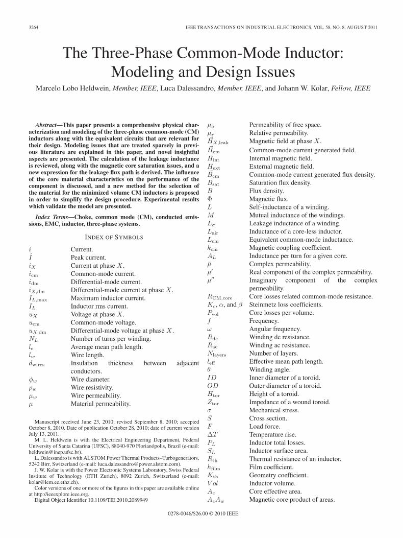
Fig. 2. (a) Currents and magnetic fields in a three-phase CM inductor withfinite permeability. (b) Schematics of a purely inductive three-phase CMinductor.
the differential-mode (DM) currents is higher than a tighterwinding.
Due to safety requirements, the maximum earth leakagecurrents are limited, and the value of the capacitors that canbe connected from the ac power lines to the protective earth islimited to the nanofarad range. For a CM filter, this limitationimplies, in the case of larger inductors, compensating for thesmall capacitors. If separated inductors are used at each powerline, a large peak flux density is expected due to the largevalues of the low-frequency DM currents. Therefore, the low-permeability core materials would be required, leading to bulkyinductors. There are three ways to reduce the magnetic fieldin a core, which are the following: 1) reduce the number ofturns of the windings; 2) reduce the current; and 3) construct thewindings in such a way that the fields created by each of themoppose the fields of the others so that the net field is reduced.The third alternative is explored in CM inductors by engineerssince the early days of radio engineering [11], [12]. It was notuntil 1966 that this component received the name “commonmode choke” [13] in the literature. In 1970, a mathematicalmodel [12] was presented for a two-line inductor.
The principle of a conventional three-phase CM inductor isshown in Fig. 2(a). The CM current icm generates the magneticfields in each of the windings, which are all on the samedirection, and ideally, the total net field ( �Hcm) is the scalar sumof each single one. For DM currents iA,dm, iB,dm, and iC,dm,where
iA,dm + iB,dm + iC,dm = 0 (1)
3266 IEEE TRANSACTIONS ON INDUSTRIAL ELECTRONICS, VOL. 58, NO. 8, AUGUST 2011
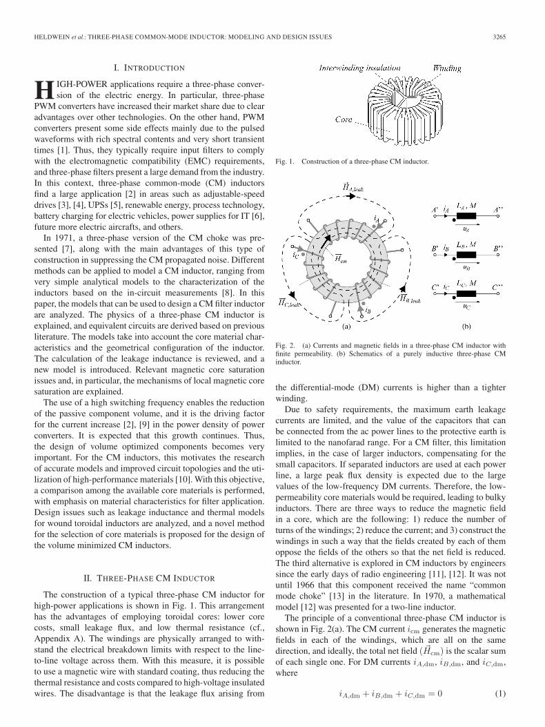
Fig. 3. Distributions of the magnetic field ( �Hcm) and flux density ( �Bcm) forthe CM currents.
the net flux in the core for an infinite relative permeability andfor the same number of turns NL in the windings is
NLiA,dm
le+
NLiB,dm
le+
NLiC,dm
le= 0. (2)
Thus, an ideal three-phase CM inductor eliminates the in-fluence of the DM currents. However, in case of a finitepermeability, part of the magnetic field generated by the DMcurrents ( �HA,leak, �HB,leak, and �HC,leak) is distributed throughthe surrounding media and is not negligible. This portion of themagnetic field is named leakage field and is responsible for achange in the internal fields, which must be considered. Thus,depending on the direction of the DM currents, the CM field isstronger or weaker in different portions of the core.
From the CM currents shown in Fig. 2(a), the magneticfield ( �Hcm) and the magnetic flux density ( �Bcm) present thedistributions shown in Fig. 3, which are similar as that for thesingle-phase CM inductor [14]. An exponential distribution isexpected, where the space that is close to the inner conductorspresents a higher field than the external side.
The circuit schematics for a purely inductive and symmet-rically built three-phase CM inductor are shown in Fig. 2(b).Three mutually coupled inductors reproduce the behavior previ-ously explained from a circuit theory perspective. Consideringthat LA = LB = LC = L, it follows that⎡
⎣ uA
uB
uC
⎤⎦ =
⎡⎣ L M M
M L MM M L
⎤⎦ · d
dt
⎡⎣ iA
iBiC
⎤⎦ . (3)
The mutual inductance M is defined by
M = kcmL. (4)
From (3) and (4), two inductances can be evaluated. The CMinductance is due to three identical currents (iA = iB = iC =icm). Hence, uA = uB = uC = ucm, and the resulting CMinductance Lcm is defined as
Lcm =ucm
dicm/dt= L + M + M = L
1 + 2kcm
3(5)
where kcm is the magnetic coupling coefficient among thedifferent windings.
According to (5), the CM impedance is equivalent to the self-inductance of a winding if kcm = 1. This shows the importanceof a high interwinding coupling in a CM inductor.
If three DM currents are considered, then iA,dm + iB,dm +iC,dm = 0, and uA,dm + uB,dm + uC,dm = 0. It follows that⎡⎣ uA,dm
uB,dm
uC,dm
⎤⎦=
⎡⎣L − M 0 0
0 L − M 00 0 L − M
⎤⎦· d
dt
⎡⎣ iA,dm
iB,dm
iC,dm
⎤⎦ .
(6)
If the DM inductance is defined as the leakage inductance Lσ
Lσ =ui,dm
dii,dm/dt= L − M, with i = A,B,C (7)
it follows that
Lσ = L · (1 − kcm). (8)
If a coupling kcm = 1 is considered, the leakage inductanceis zero. The effects of the DM inductances are not simple tomodel in a complete filter because of the external couplingswith other components. The utilization of the DM inductancesin filtering the DM currents might be very useful, but this appli-cation requires a careful analysis in order to reduce the radiatedemissions and deterioration of the filtering performance due toexternal couplings.
From the previous analysis, the model of a CM inductor canbe divided into two parts: one for the symmetrical currents andthe other for the asymmetrical currents. This provides a usefulsimplification for the following analysis.
III. CM INDUCTOR DESIGN PARAMETERS
A. CM Inductance
The three-phase CM inductor is made out of three windingsin parallel and is wound in the same direction as the CMcurrents. Therefore, as for a conventional DM inductor, the self-inductance of the windings around the ferromagnetic core isdependent on the real part μ′ of the complex permeability μ[18]. However, unlike the DM inductors, the dependence of thepermeability on the DM currents is typically very small due tothe reduced net flux. Typical CM currents are of low amplitudeso that the magnetic flux in the core does not create largevariations in the core’s permeability. Thus, the CM inductanceLCM can be defined as a function of the frequency f , numberof turns NL, and inductance per turn AL of the core by
LCM(f) = ALN2L · μ′(f)
|μ(f = 0 Hz)| . (9)
Since the CM currents typically generate low flux densities,high-permeability materials can be used to achieve small di-mensions. The proper choice of core materials leads to compactinductors and reduced parasitics. Nevertheless, the materialsfor the CM inductors present a highly variable complex per-meability with frequency. The real part of the series complexpermeability for some high-performance magnetic materials isshown in Fig. 4(a). Two types of ferrite (N30 and T38 [16]), a
HELDWEIN et al.: THREE-PHASE COMMON-MODE INDUCTOR: MODELING AND DESIGN ISSUES 3267
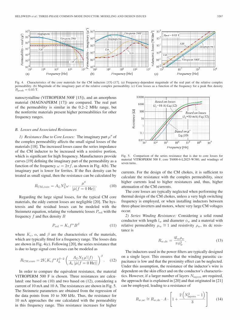
Fig. 4. Characteristics of the core materials for the CM inductors [15]–[17]. (a) Frequency-dependent magnitude of the real part of the relative complexpermeability. (b) Magnitude of the imaginary part of the relative complex permeability. (c) Core losses as a function of the frequency for a peak flux densityBpeak = 0.05 T.
nanocrystalline (VITROPERM 500F [15]), and an amorphousmaterial (MAGNAPERM [17]) are compared. The real partof the permeability is similar in the 0.2–2 MHz range, butthe nonferrite materials present higher permeabilities for otherfrequency ranges.
B. Losses and Associated Resistances
1) Resistance Due to Core Losses: The imaginary part μ′′ ofthe complex permeability affects the small signal losses of thematerials [18]. The increased losses cause the series impedanceof the CM inductor to be increased with a resistive portion,which is significant for high frequency. Manufacturers providecurves [19] defining the imaginary part of the permeability as afunction of the frequency ω = 2πf , as shown in Fig. 4(b). Theimaginary part is lower for ferrites. If the flux density can betreated as small signal, then the resistance can be calculated by
RCM,core = ALN2Lω · μ′′
|μ(f = 0 Hz)| . (10)
Regarding the large signal losses, for the typical CM corematerials, the eddy current losses are negligible [20]. The hys-teresis and the residual losses can be modeled with theSteinmetz equation, relating the volumetric losses Pvol with thefrequency f and flux density B
Pvol = KcfαBβ (11)
where Kc, α, and β are the characteristics of the materials,which are typically fitted for a frequency range. The losses dataare shown in Fig. 4(c). Following [20], the series resistance thatis due to large signal core losses can be modeled as
RCM,core = 2VcKcfαIβ−2
L
(ALNLμ′(f)
Ae |μ(f = 0 Hz)|
)β
. (12)
In order to compare the equivalent resistance, the materialVITROPERM 500 F is chosen. Three resistances are calcu-lated: one based on (10) and two based on (12), considering acurrent of 10 mA and 10 A. The resistances are shown in Fig. 5.The Steinmetz parameters are obtained from the regression ofthe data points from 10 to 300 kHz. Thus, the resistance for10 mA approaches the one calculated with the permeabilityin this frequency range. This resistance increases for higher
Fig. 5. Comparison of the series resistance that is due to core losses formaterial VITROPERM 500 F, core T6000-6-L2025-W380, and windings ofseven turns.
currents. For the design of the CM chokes, it is sufficient tocalculate the resistance with the complex permeability, sincehigher currents lead to higher resistances and, thus, higherattenuation of the CM currents.
The core losses are typically neglected when performing thethermal design of the CM chokes, unless a very high switchingfrequency is employed, or when installing inductors betweenthree-phase inverters and motors, where very large CM voltagesoccur.
2) Series Winding Resistance: Considering a solid roundconductor with length lw and diameter φw and a material withrelative permeability μw
∼= 1 and resistivity ρw, its dc resis-tance is
Rw,dc =4lwρw
πφ2w
. (13)
The inductors used in the power filters are typically designedon a single layer. This ensures that the winding parasitic ca-pacitance is low and that the proximity effect can be neglected.Under this assumption, the resistance of the inductor’s wire isdependent on the skin effect and on the conductor’s characteris-tics. However, if a larger number of layers Nlayers are required,the approach that is explained in [20] and that originated in [21]can be employed, leading to a resistance of
Rw,ac∼= Rw,dc · A ·
⎡⎣1 +
2(N2
layers − 1)
3
⎤⎦ (14)
3268 IEEE TRANSACTIONS ON INDUSTRIAL ELECTRONICS, VOL. 58, NO. 8, AUGUST 2011
Fig. 6. Parasitic capacitance network model for a three-phase CM inductor.
with
A =(π
4
) 34 ·
√φ3
w
δ√
dwires
(15)
where dwires indicates the distance between two adjacent con-ductors. In order to profit from the skin effect to achievehigher impedances at high frequency, solid round conductorsare used instead of Litz wires [22]. The precise calculation ofthe winding losses has been analyzed in [23]–[27].
These expressions are valid for the frequency range f underthe conditions
if Nlayers = 1 ⇒ f ≥ ρwdwires
πμwφ3w
·(
4π
) 32
(16)
if Nlayers > 1 ⇒ f ≥ 16ρwdwires
πμwφ3w
·(
4π
) 32
. (17)
C. Parasitic Parallel Capacitance
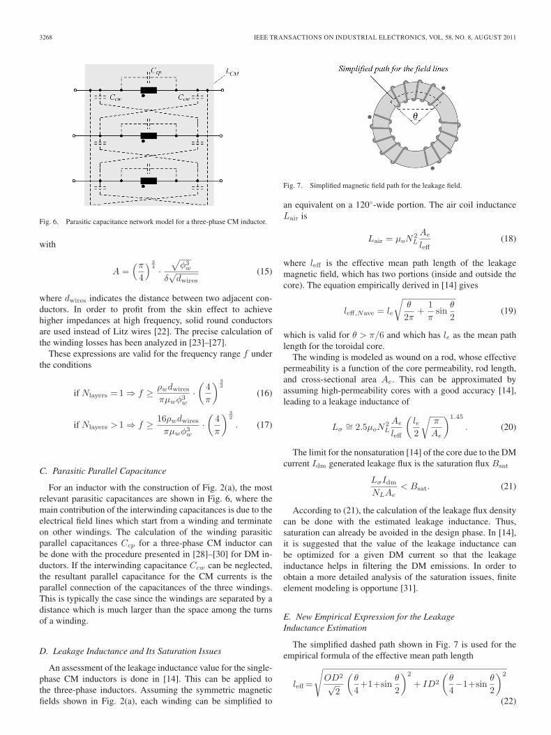
For an inductor with the construction of Fig. 2(a), the mostrelevant parasitic capacitances are shown in Fig. 6, where themain contribution of the interwinding capacitances is due to theelectrical field lines which start from a winding and terminateon other windings. The calculation of the winding parasiticparallel capacitances Ccp for a three-phase CM inductor canbe done with the procedure presented in [28]–[30] for DM in-ductors. If the interwinding capacitance Ccw can be neglected,the resultant parallel capacitance for the CM currents is theparallel connection of the capacitances of the three windings.This is typically the case since the windings are separated by adistance which is much larger than the space among the turnsof a winding.
D. Leakage Inductance and Its Saturation Issues
An assessment of the leakage inductance value for the single-phase CM inductors is done in [14]. This can be applied tothe three-phase inductors. Assuming the symmetric magneticfields shown in Fig. 2(a), each winding can be simplified to
Fig. 7. Simplified magnetic field path for the leakage field.
an equivalent on a 120◦-wide portion. The air coil inductanceLair is
Lair = μoN2L
Ae
leff(18)
where leff is the effective mean path length of the leakagemagnetic field, which has two portions (inside and outside thecore). The equation empirically derived in [14] gives
leff,Nave = le
√θ
2π+
1π
sinθ
2(19)
which is valid for θ > π/6 and which has le as the mean pathlength for the toroidal core.
The winding is modeled as wound on a rod, whose effectivepermeability is a function of the core permeability, rod length,and cross-sectional area Ae. This can be approximated byassuming high-permeability cores with a good accuracy [14],leading to a leakage inductance of
Lσ∼= 2.5μoN
2L
Ae
leff
(le2
√π
Ae
)1.45
. (20)
The limit for the nonsaturation [14] of the core due to the DMcurrent Idm generated leakage flux is the saturation flux Bsat
LσIdm
NLAe< Bsat. (21)
According to (21), the calculation of the leakage flux densitycan be done with the estimated leakage inductance. Thus,saturation can already be avoided in the design phase. In [14],it is suggested that the value of the leakage inductance canbe optimized for a given DM current so that the leakageinductance helps in filtering the DM emissions. In order toobtain a more detailed analysis of the saturation issues, finiteelement modeling is opportune [31].
E. New Empirical Expression for the LeakageInductance Estimation
The simplified dashed path shown in Fig. 7 is used for theempirical formula of the effective mean path length
leff =
√OD2
√2
(θ
4+1+sin
θ
2
)2
+ ID2
(θ
4−1+sin
θ
2
)2
(22)
HELDWEIN et al.: THREE-PHASE COMMON-MODE INDUCTOR: MODELING AND DESIGN ISSUES 3269
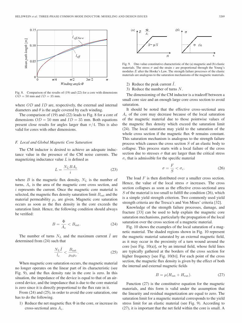
Fig. 8. Comparison of the results of (19) and (22) for a core with dimensionsOD = 50 mm and ID = 35 mm.
where OD and ID are, respectively, the external and internaldiameters and θ is the angle covered by each winding.
The comparison of (19) and (22) leads to Fig. 8 for a core ofdimensions OD = 50 mm and ID = 35 mm. Both equationspresent close results for angles larger than π/4. This is alsovalid for cores with other dimensions.
F. Local and Global Magnetic Core Saturation
The CM inductor is desired to achieve an adequate induc-tance value in the presence of the CM noise currents. Themagnetizing inductance value L is defined as
L =NLBAe
i(23)
where B is the magnetic flux density, NL is the number ofturns, Ae is the area of the magnetic core cross section, andi represents the current. Once the magnetic core material isselected, the magnetic flux density saturation limit Bsat and thematerial permeability μr are given. Magnetic core saturationoccurs as soon as the flux density in the core exceeds thesaturation limit. Hence, the following condition should alwaysbe verified:
B =ΦAe
< Bsat. (24)
The number of turns NL and the maximum current I aredetermined from (24) such that
NLI
le<
Bsat
μ0μr. (25)
When magnetic core saturation occurs, the magnetic materialno longer operates on the linear part of its characteristic (seeFig. 9), and the flux density rate in the core is zero. In thissituation, the impedance of the device is equal to that of an air-cored device, and the impedance that is due to the core materialis zero since it is directly proportional to the flux rate in it.
From (24) and (25), in order to avoid the core saturation, onehas to do the following.
1) Reduce the net magnetic flux Φ in the core, or increase itscross-sectional area Ae.
Fig. 9. One-value constitutive characteristic of the (a) magnetic and (b) elasticmaterials. The stress σ and the strain ε are proportional through the Young’smodulus E after the Hooke’s Law. The strength failure processes of the elasticmaterials are analogous to the saturation mechanisms of the magnetic materials.
2) Reduce the peak current I .3) Reduce the number of turns N .The dimensioning of the CM inductor is a tradeoff between a
small core size and an enough large core cross section to avoidsaturation.
It should be noted that the effective cross-sectional areaAe of the core may decrease because of the local saturationof the magnetic material due to those pointwise values ofthe magnetic flux density which exceed the saturation limit(24). The local saturation may yield to the saturation of thewhole cross section if the magnetic flux Φ remains constant.This saturation mechanism is analogous to the strength failureprocess which causes the cross section S of an elastic body tocollapse. This process starts with a local failure of the crosssection due to stresses σ that are larger than the critical stressσc that is admissible for the specific material
σ =F
S< σc. (26)
The load F is then distributed over a smaller cross section.Hence, the value of the local stress σ increases. The crosssection collapses as soon as the effective cross-sectional areaS of the material is too small to fulfill the condition (26), whichis a simple yield strength criterion. Two commonly used yieldstrength criteria are the Tresca’s and Von Mises’ criteria [32].
Knowledge of the strength failure processes, damage, andfracture [33] can be used to help explain the magnetic coresaturation mechanisms, particularly the propagation of the localsaturation over the cross section of a magnetic material.
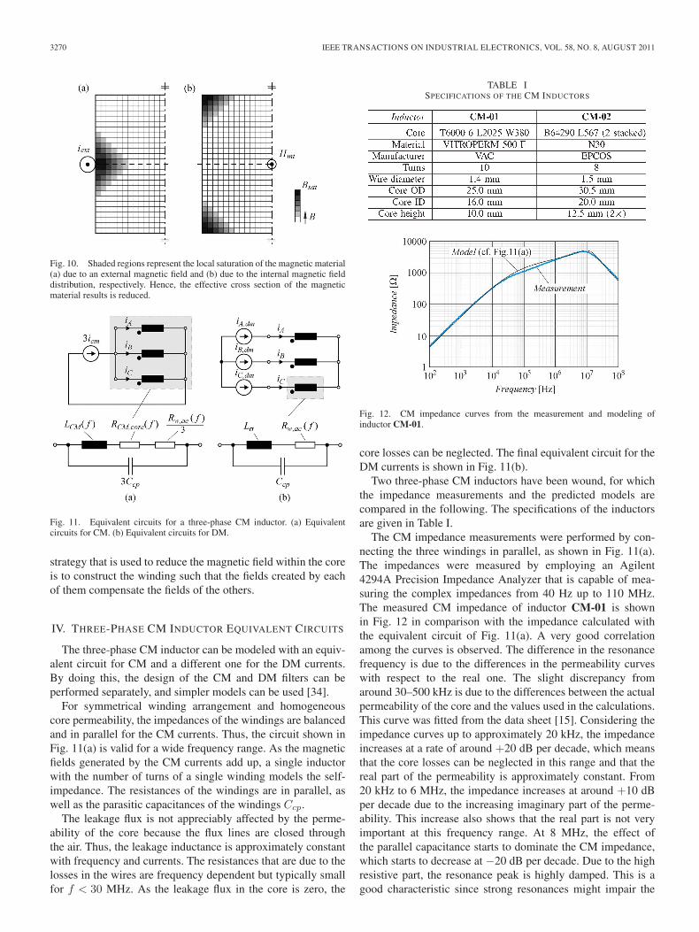
Fig. 10 shows the examples of the local saturation of a mag-netic material. The shaded regions shown in Fig. 10 representthe magnetic material saturated by an external magnetic field,as it may occur in the proximity of a turn wound around thecore [see Fig. 10(a)], or by an internal field, whose field linesare typically gathered at the borders of the cross section forhigher frequency [see Fig. 10(b)]. For each point of the crosssection, the magnetic flux density is given by the effect of boththe internal and external magnetic fields
B = μ(Hint + Hext). (27)
Function (27) is the constitutive equation for the magneticmaterials, and this form is valid under the assumption thatthe linearity and residual magnetization are equal to zero. Thesaturation limit for a magnetic material corresponds to the yieldstress limit for an elastic material (see Fig. 9). According to(27), it is important that the net field within the core is small. A
3270 IEEE TRANSACTIONS ON INDUSTRIAL ELECTRONICS, VOL. 58, NO. 8, AUGUST 2011
Fig. 10. Shaded regions represent the local saturation of the magnetic material(a) due to an external magnetic field and (b) due to the internal magnetic fielddistribution, respectively. Hence, the effective cross section of the magneticmaterial results is reduced.
Fig. 11. Equivalent circuits for a three-phase CM inductor. (a) Equivalentcircuits for CM. (b) Equivalent circuits for DM.
strategy that is used to reduce the magnetic field within the coreis to construct the winding such that the fields created by eachof them compensate the fields of the others.
IV. THREE-PHASE CM INDUCTOR EQUIVALENT CIRCUITS
The three-phase CM inductor can be modeled with an equiv-alent circuit for CM and a different one for the DM currents.By doing this, the design of the CM and DM filters can beperformed separately, and simpler models can be used [34].
For symmetrical winding arrangement and homogeneouscore permeability, the impedances of the windings are balancedand in parallel for the CM currents. Thus, the circuit shown inFig. 11(a) is valid for a wide frequency range. As the magneticfields generated by the CM currents add up, a single inductorwith the number of turns of a single winding models the self-impedance. The resistances of the windings are in parallel, aswell as the parasitic capacitances of the windings Ccp.
The leakage flux is not appreciably affected by the perme-ability of the core because the flux lines are closed throughthe air. Thus, the leakage inductance is approximately constantwith frequency and currents. The resistances that are due to thelosses in the wires are frequency dependent but typically smallfor f < 30 MHz. As the leakage flux in the core is zero, the
TABLE ISPECIFICATIONS OF THE CM INDUCTORS
Fig. 12. CM impedance curves from the measurement and modeling ofinductor CM-01.
core losses can be neglected. The final equivalent circuit for theDM currents is shown in Fig. 11(b).
Two three-phase CM inductors have been wound, for whichthe impedance measurements and the predicted models arecompared in the following. The specifications of the inductorsare given in Table I.
The CM impedance measurements were performed by con-necting the three windings in parallel, as shown in Fig. 11(a).The impedances were measured by employing an Agilent4294A Precision Impedance Analyzer that is capable of mea-suring the complex impedances from 40 Hz up to 110 MHz.The measured CM impedance of inductor CM-01 is shownin Fig. 12 in comparison with the impedance calculated withthe equivalent circuit of Fig. 11(a). A very good correlationamong the curves is observed. The difference in the resonancefrequency is due to the differences in the permeability curveswith respect to the real one. The slight discrepancy fromaround 30–500 kHz is due to the differences between the actualpermeability of the core and the values used in the calculations.This curve was fitted from the data sheet [15]. Considering theimpedance curves up to approximately 20 kHz, the impedanceincreases at a rate of around +20 dB per decade, which meansthat the core losses can be neglected in this range and that thereal part of the permeability is approximately constant. From20 kHz to 6 MHz, the impedance increases at around +10 dBper decade due to the increasing imaginary part of the perme-ability. This increase also shows that the real part is not veryimportant at this frequency range. At 8 MHz, the effect ofthe parallel capacitance starts to dominate the CM impedance,which starts to decrease at −20 dB per decade. Due to the highresistive part, the resonance peak is highly damped. This is agood characteristic since strong resonances might impair the
HELDWEIN et al.: THREE-PHASE COMMON-MODE INDUCTOR: MODELING AND DESIGN ISSUES 3271
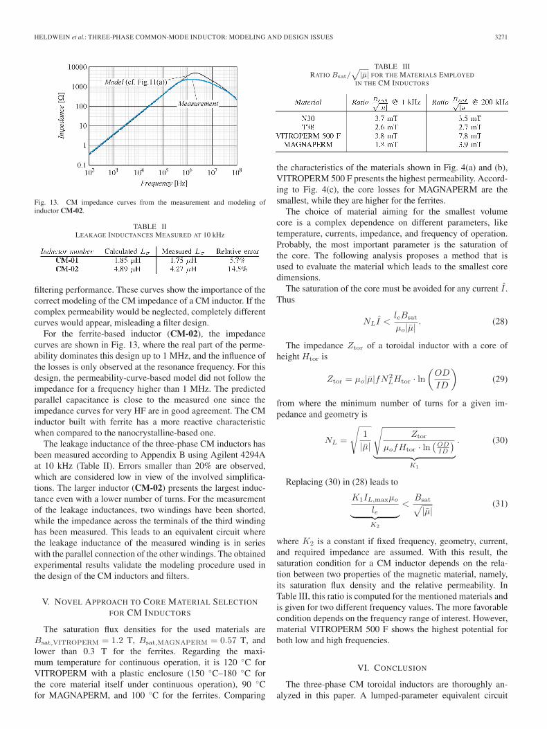
Fig. 13. CM impedance curves from the measurement and modeling ofinductor CM-02.
TABLE IILEAKAGE INDUCTANCES MEASURED AT 10 kHz
filtering performance. These curves show the importance of thecorrect modeling of the CM impedance of a CM inductor. If thecomplex permeability would be neglected, completely differentcurves would appear, misleading a filter design.
For the ferrite-based inductor (CM-02), the impedancecurves are shown in Fig. 13, where the real part of the perme-ability dominates this design up to 1 MHz, and the influence ofthe losses is only observed at the resonance frequency. For thisdesign, the permeability-curve-based model did not follow theimpedance for a frequency higher than 1 MHz. The predictedparallel capacitance is close to the measured one since theimpedance curves for very HF are in good agreement. The CMinductor built with ferrite has a more reactive characteristicwhen compared to the nanocrystalline-based one.
The leakage inductance of the three-phase CM inductors hasbeen measured according to Appendix B using Agilent 4294Aat 10 kHz (Table II). Errors smaller than 20% are observed,which are considered low in view of the involved simplifica-tions. The larger inductor (CM-02) presents the largest induc-tance even with a lower number of turns. For the measurementof the leakage inductances, two windings have been shorted,while the impedance across the terminals of the third windinghas been measured. This leads to an equivalent circuit wherethe leakage inductance of the measured winding is in serieswith the parallel connection of the other windings. The obtainedexperimental results validate the modeling procedure used inthe design of the CM inductors and filters.
V. NOVEL APPROACH TO CORE MATERIAL SELECTION
FOR CM INDUCTORS
The saturation flux densities for the used materials areBsat,VITROPERM = 1.2 T, Bsat,MAGNAPERM = 0.57 T, andlower than 0.3 T for the ferrites. Regarding the maxi-mum temperature for continuous operation, it is 120 ◦C forVITROPERM with a plastic enclosure (150 ◦C–180 ◦C forthe core material itself under continuous operation), 90 ◦Cfor MAGNAPERM, and 100 ◦C for the ferrites. Comparing
TABLE IIIRATIO Bsat/
√|μ| FOR THE MATERIALS EMPLOYED
IN THE CM INDUCTORS
the characteristics of the materials shown in Fig. 4(a) and (b),VITROPERM 500 F presents the highest permeability. Accord-ing to Fig. 4(c), the core losses for MAGNAPERM are thesmallest, while they are higher for the ferrites.
The choice of material aiming for the smallest volumecore is a complex dependence on different parameters, liketemperature, currents, impedance, and frequency of operation.Probably, the most important parameter is the saturation ofthe core. The following analysis proposes a method that isused to evaluate the material which leads to the smallest coredimensions.
The saturation of the core must be avoided for any current I .Thus
NLI <leBsat
μo|μ|. (28)
The impedance Ztor of a toroidal inductor with a core ofheight Htor is
Ztor = μo|μ|fN2LHtor · ln
(OD
ID
)(29)
from where the minimum number of turns for a given im-pedance and geometry is
NL =
√1|μ|
√Ztor
μofHtor · ln(
ODID
)︸ ︷︷ ︸
K1
. (30)
Replacing (30) in (28) leads to
K1IL,maxμo
le︸ ︷︷ ︸K2
<Bsat√|μ|
(31)
where K2 is a constant if fixed frequency, geometry, current,and required impedance are assumed. With this result, thesaturation condition for a CM inductor depends on the rela-tion between two properties of the magnetic material, namely,its saturation flux density and the relative permeability. InTable III, this ratio is computed for the mentioned materials andis given for two different frequency values. The more favorablecondition depends on the frequency range of interest. However,material VITROPERM 500 F shows the highest potential forboth low and high frequencies.
VI. CONCLUSION
The three-phase CM toroidal inductors are thoroughly an-alyzed in this paper. A lumped-parameter equivalent circuit
3272 IEEE TRANSACTIONS ON INDUSTRIAL ELECTRONICS, VOL. 58, NO. 8, AUGUST 2011
is derived, and punctual references to previous literature areprovided. The modeling aspects that are related to the physicalconstruction of the toroidal three-phase CM inductors wereaddressed, and a novel method for the selection of the corematerials was proposed for the volume minimization of the CMinductors.
The impedances of the model present a strong dependenceon the construction and the core material. A method for theselection of the material for the CM inductors was proposed,which simplifies the design and allows for the minimum volumeinductors in a given frequency range of application. The calcu-lation of the leakage inductance was reviewed, along with therelated saturation issues, and a novel expression was proposed.The experimental results validate the modeling procedure.
Furthermore, the mechanisms of the capacitive noise cou-pling in the three-phase EMC filters were briefly described.The main parasitic capacitive connections are constituted bythe parasitic capacitances of the used filtering inductors. Theseeffects can be reduced by using the capacitance cancellationtechniques.
APPENDIX ATHERMAL MODELS FOR THE TOROIDAL CORES
The temperature rise of a filter inductor typically defines acore for a given application due to the employed material tem-perature limitations. Aiming for the smallest size, consequentlycheaper cores, forces a filter designer to search for the mostprecise thermal models. Core manufacturers such as MagneticsInc. [35] and Micrometals Inc. [36] and specialized literature[37] suggest that the expression
ΔT =(
PL [mW]SL [cm2]
)0.833
(32)
where PL is the total inductor losses and SL is the woundinductor surface are, provides a good approximation of thetemperature rise ΔT in a core. This is a difficult calculationsince the exact computation of the outer surface of an inductormight prove to be a big challenge. The assumption for thisexpression is that the inductor presents a 40% filling factor,and it is typically mounted on a printed circuit board. Thus,this is a special case of heat transfer based on typical boundaryconditions. The classical expression for the convection-basedthermal resistance Rth of a body of surface SL is given by
Rth =1
hfilmSL(33)
where the film coefficient hfilm is strongly dependent on theboundary conditions, i.e., in parameters like material character-istics, temperature, surrounding media, surface finish, distanceto other bodies, and air or fluid speed. The film coefficient caneasily vary by orders of magnitude depending on air speed anddistance to other bodies. A more easily applicable model basedon (33) is proposed in [38], where the thermal resistance Rth ofa core is calculated with
Rth =ΔT
PL=
Kth
V ol2/3(34)
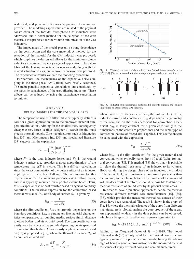
Fig. 14. Thermal resistance of the toroidal cores from different manufacturers[15], [35], [36] as presented in their catalogs and proposed approximation.
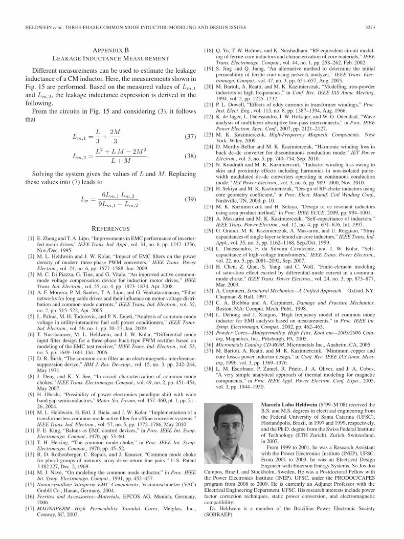
Fig. 15. Inductance measurements performed in order to evaluate the leakageinductance of a three-phase CM inductor.
where, instead of the outer surface, the volume V ol of theinductor is used and a coefficient Kth depends on the geometryof the core and on the film coefficient for convection. Coef-ficient Kth is fairly constant for a given core family if thedimensions of the cores are proportional and the same type ofconvection (natural or forced air) is applied. This coefficient canbe calculated with the expression
Kth =V ol2/3
hfilmSL(35)
where hfilm is the film coefficient for the given material andconvection, which typically varies from 10 to 25 W/m2 for nat-ural convection [38]. This method [38] shows that it is possibleto relate the thermal resistance of an inductor to its volume.However, during the design phase of an inductor, the productof the areas AeAw is sometimes a more useful parameter thanthe volume, and a relation between the product of the areas andvolume does exist. Therefore, it should be possible to define thethermal resistance of an inductor by its product of the areas.
In order to have a practical approach to define the thermalresistance, different toroidal core manufacturers [15], [35],[36], which provide the measured thermal resistances of theircores, have been researched. The result is shown in the graph ofFig. 14, where the thermal resistance of the cores from differentmanufacturers is plotted against the core product of the areas.An exponential tendency in the data points can be observed,which can be approximated by least squares regression to
Rth∼= 415.17
(AeAw [mm4]
)−0.3593 [K/W] (36)
leading to an R-squared factor of R2 = 0.9979. The modelobtained with (36) is only valid for the toroidal cores that aretypically mounted in printed circuit boards, having the advan-tage of being a good approximation for the measured thermalresistance of many different cores and core manufacturers.
HELDWEIN et al.: THREE-PHASE COMMON-MODE INDUCTOR: MODELING AND DESIGN ISSUES 3273
APPENDIX BLEAKAGE INDUCTANCE MEASUREMENT
Different measurements can be used to estimate the leakageinductance of a CM inductor. Here, the measurements shown inFig. 15 are performed. Based on the measured values of Lm,1
and Lm,2, the leakage inductance expression is derived in thefollowing.
From the circuits in Fig. 15 and considering (3), it followsthat
Lm,1 =L
3+
2M
3(37)
Lm,2 =L2 + LM − 2M2
L + M. (38)
Solving the system gives the values of L and M . Replacingthese values into (7) leads to
Lσ =6Lm,1 Lm,2
9Lm,1 − Lm,2. (39)
REFERENCES
[1] E. Zhong and T. A. Lipo, “Improvements in EMC performance of inverter-fed motor drives,” IEEE Trans. Ind. Appl., vol. 31, no. 6, pp. 1247–1256,Nov./Dec. 1995.
[2] M. L. Heldwein and J. W. Kolar, “Impact of EMC filters on the powerdensity of modern three-phase PWM converters,” IEEE Trans. PowerElectron., vol. 24, no. 6, pp. 1577–1588, Jun. 2009.
[3] M. C. Di Piazza, G. Tine, and G. Vitale, “An improved active common-mode voltage compensation device for induction motor drives,” IEEETrans. Ind. Electron., vol. 55, no. 4, pp. 1823–1834, Apr. 2008.
[4] A. F. Moreira, P. M. Santos, T. A. Lipo, and G. Venkataramanan, “Filternetworks for long cable drives and their influence on motor voltage distri-bution and common-mode currents,” IEEE Trans. Ind. Electron., vol. 52,no. 2, pp. 515–522, Apr. 2005.
[5] L. Palma, M. H. Todorovic, and P. N. Enjeti, “Analysis of common-modevoltage in utility-interactive fuel cell power conditioners,” IEEE Trans.Ind. Electron., vol. 56, no. 1, pp. 20–27, Jan. 2009.
[6] T. Nussbaumer, M. L. Heldwein, and J. W. Kolar, “Differential modeinput filter design for a three-phase buck-type PWM rectifier based onmodeling of the EMC test receiver,” IEEE Trans. Ind. Electron., vol. 53,no. 5, pp. 1649–1661, Oct. 2006.
[7] D. R. Bush, “The common-core filter as an electromagnetic interference-suppression device,” IBM J. Res. Develop., vol. 15, no. 3, pp. 242–244,May 1971.
[8] J. Deng and K. Y. See, “In-circuit characterization of common-modechokes,” IEEE Trans. Electromagn. Compat., vol. 49, no. 2, pp. 451–454,May 2007.
[9] H. Ohashi, “Possibility of power electronics paradigm shift with wideband gap semiconductors,” Mater. Sci. Forum, vol. 457–460, pt. 1, pp. 21–26, 2004.
[10] M. L. Heldwein, H. Ertl, J. Biela, and J. W. Kolar, “Implementation of atransformerless common-mode active filter for offline converter systems,”IEEE Trans. Ind. Electron., vol. 57, no. 5, pp. 1772–1786, May 2010.
[11] F. E. King, “Baluns as EMC control devices,” in Proc. IEEE Int. Symp.Electromagn. Compat., 1970, pp. 53–60.
[12] T. H. Herring, “The common mode choke,” in Proc. IEEE Int. Symp.Electromagn. Compat., 1970, pp. 45–52.
[13] R. D. Rothenberger, C. Rapids, and J. Krauser, “Common mode chokefor plural groups of memory array drive-return line pairs,” U.S. Patent3 482 227, Dec. 2, 1969.
[14] M. J. Nave, “On modeling the common mode inductor,” in Proc. IEEEInt. Symp. Electromagn. Compat., 1991, pp. 452–457.
[15] Nanocrystalline Vitroperm EMC Components, Vacuumschmelze (VAC)GmbH Co., Hanau, Germany, 2004.
[16] Ferrites and Accessories—Materials, EPCOS AG, Munich, Germany,2006.
[17] MAGNAPERM—High Permeability Toroidal Cores, Metglas, Inc.,Conway, SC, 2003.
[18] Q. Yu, T. W. Holmes, and K. Naishadham, “RF equivalent circuit model-ing of ferrite-core inductors and characterization of core materials,” IEEETrans. Electromagn. Compat., vol. 44, no. 1, pp. 258–262, Feb. 2002.
[19] S. Jing and Q. Jiang, “An alternative method to determine the initialpermeability of ferrite core using network analyzer,” IEEE Trans. Elec-tromagn. Compat., vol. 47, no. 3, pp. 651–657, Aug. 2005.
[20] M. Bartoli, A. Reatti, and M. K. Kazimierczuk, “Modelling iron-powderinductors at high frequencies,” in Conf. Rec. IEEE IAS Annu. Meeting,1994, vol. 2, pp. 1225–1232.
[21] P. L. Dowell, “Effects of eddy currents in transformer windings,” Proc.Inst. Elect. Eng., vol. 113, no. 8, pp. 1387–1394, Aug. 1966.
[22] K. de Jager, L. Dalessandro, I. W. Hofsajer, and W. G. Odendaal, “Waveanalysis of multilayer absorptive low-pass interconnects,” in Proc. IEEEPower Electron. Spec. Conf., 2007, pp. 2121–2127.
[23] M. K. Kazimierczuk, High-Frequency Magnetic Components. NewYork: Wiley, 2009.
[24] D. Murthy-Bellur and M. K. Kazimierczuk, “Harmonic winding loss inbuck dc–dc converter for discontinuous conduction mode,” IET PowerElectron., vol. 3, no. 5, pp. 740–754, Sep. 2010.
[25] N. Kondrath and M. K. Kazimierczuk, “Inductor winding loss owing toskin and proximity effects including harmonics in non-isolated pulse-width modulated dc–dc converters operating in continuous conductionmode,” IET Power Electron., vol. 3, no. 6, pp. 989–1000, Nov. 2010.
[26] H. Sekiya and M. K. Kazimierczuk, “Design of RF-choke inductors usingcore geometry coefficient,” in Proc. Elect. Manuf. Coil Winding Conf.,Nashville, TN, 2009, p. 10.
[27] M. K. Kazimierczuk and H. Sekiya, “Design of ac resonant inductorsusing area product method,” in Proc. IEEE ECCE, 2009, pp. 994–1001.
[28] A. Massarini and M. K. Kazimierczuk, “Self-capacitance of inductors,”IEEE Trans. Power Electron., vol. 12, no. 4, pp. 671–676, Jul. 1997.
[29] G. Grandi, M. K. Kazimierczuk, A. Massarini, and U. Reggiani, “Straycapacitances of single-layer solenoid air-core inductors,” IEEE Trans. Ind.Appl., vol. 35, no. 5, pp. 1162–1168, Sep./Oct. 1999.
[30] L. Dalessandro, F. da Silveira Cavalcante, and J. W. Kolar, “Self-capacitance of high-voltage transformers,” IEEE Trans. Power Electron.,vol. 22, no. 5, pp. 2081–2092, Sep. 2007.
[31] H. Chen, Z. Qian, S. Yang, and C. Wolf, “Finite-element modelingof saturation effect excited by differential-mode current in a common-mode choke,” IEEE Trans. Power Electron., vol. 24, no. 3, pp. 873–877,Mar. 2009.
[32] A. Carpinteri, Structural Mechanics—A Unified Approach. Oxford, NY:Chapman & Hall, 1997.
[33] C. A. Brebbia and A. Carpinteri, Damage and Fracture Mechanics.Boston, MA: Comput. Mech. Publ., 1998.
[34] L. Dehong and J. Xanguo, “High frequency model of common modeinductor for EMI analysis based on measurements,” in Proc. IEEE Int.Symp. Electromagn. Compat., 2002, pp. 462–465.
[35] Powder Cores—Molypermalloy, High Flux, Kool mu—2005/2006 Cata-log, Magnetics, Inc., Pittsburgh, PA, 2005.
[36] Micrometals Catalog CD-ROM, Micrometals Inc., Anaheim, CA, 2005.[37] M. Bartoli, A. Reatti, and M. K. Kazimierczuk, “Minimum copper and
core losses power inductor design,” in Conf. Rec. IEEE IAS Annu. Meet-ing, 1996, vol. 3, pp. 1369–1376.
[38] L. M. Escribano, P. Zumel, R. Prieto, J. A. Oliver, and J. A. Cobos,“A very simple analytical approach of thermal modeling for magneticcomponents,” in Proc. IEEE Appl. Power Electron. Conf. Expo., 2005,vol. 3, pp. 1944–1950.
Marcelo Lobo Heldwein (S’99–M’08) received theB.S. and M.S. degrees in electrical engineering fromthe Federal University of Santa Catarina (UFSC),Florianópolis, Brazil, in 1997 and 1999, respectively,and the Ph.D. degree from the Swiss Federal Instituteof Technology (ETH Zurich), Zurich, Switzerland,in 2007.
From 1999 to 2001, he was a Research Assistantwith the Power Electronics Institute (INEP), UFSC.From 2001 to 2003, he was an Electrical DesignEngineer with Emerson Energy Systems, So Jos dos
Campos, Brazil, and Stockholm, Sweden. He was a Postdoctoral Fellow withthe Power Electronics Institute (INEP), UFSC, under the PRODOC/CAPESprogram from 2008 to 2009. He is currently an Adjunct Professor with theElectrical Engineering Department, UFSC. His research interests include powerfactor correction techniques, static power conversion, and electromagneticcompatibility.
Dr. Heldwein is a member of the Brazilian Power Electronic Society(SOBRAEP).
3274 IEEE TRANSACTIONS ON INDUSTRIAL ELECTRONICS, VOL. 58, NO. 8, AUGUST 2011
Luca Dalessandro (S’02–M’07) received the M.Sc.degree (first class honors) in electrical engineeringfrom the Politecnico di Bari, Bari, Italy, in 2001 andthe Ph.D. degree in electrical engineering from theSwiss Federal Institute of Technology (ETH Zurich),Zurich, Switzerland, in 2007.
From 2001 to 2002, he was a Researcher withthe Max-Planck Institute for Mathematics in the Sci-ences (MPI-MIS), Leipzig, Germany. From 2002 to2006, he was a Research and Teaching Assistant withthe Power Electronics Systems Laboratory (PES),
ETH Zurich. In the summer of 2006, under a postdoctoral fellowship grantprovided by the industry, he joined the National Science Foundation Engi-neering Research Center (NSF-ERC) for Power Electronics Systems (CPES),Virginia Polytechnic Institute and State University (Virginia Tech), Blacksburg.In the fall of 2006, he was appointed as an Adjunct Professor with the BradleyDepartment of Electrical and Computer Engineering, Virginia Tech. From 2007to 2010, he was a Guest Research Associate with the Power Systems andHigh-Voltage Technology Institute (EEH), ETH Zurich. In 2007, he initiatedan ETH spin-off company in the field of high-performance current sensing.Since 2008, he has been with the R&D Department, ALSTOM Power, Birr,Switzerland, covering several functions as a Project Manager, Product LineManager, and Patent Officer in the field of large synchronous machines, powergeneration, and power conversion. He has been an Invited Lecturer, Visitor,and Consultant for several recognized institutions and companies, includingthe Massachusetts Institute of Technology, Cambridge; the National JapaneseInstitute for Advanced Industrial Science and Technology (AIST), Japan; theSwiss Embassy in Italy; and Asea Brown Boveri (ABB). He has authoredmore than 30 peer-reviewed technical papers and patents. His research interestsinclude all disciplines of electrical power engineering.
Dr. Dalessandro is a recipient of several awards and fellowships.
Johann W. Kolar (M’89–SM’04–F’10) receivedthe M.Sc. and Ph.D. degrees (summa cum laude/promotio sub auspiciis praesidentis rei publicae)from the University of Technology Vienna, Vienna,Austria.
Since 1984, he has been working as an indepen-dent international consultant who is in close collab-oration with the University of Technology Vienna,in the fields of power electronics, industrial elec-tronics, and high-performance drives. He has pro-posed numerous novel PWM converter topologies
and modulation and control concepts, e.g., the VIENNA rectifier and the three-phase ac–ac sparse matrix converter. He was appointed as a Professor andthe Head of the Power Electronic Systems Laboratory, Swiss Federal Instituteof Technology (ETH Zurich), Zurich, Switzerland, on February 1, 2001. Heinitiated and/or is the founder/cofounder of four spin-off companies targetingultrahigh speed drives, multidomain/level simulation, ultracompact/efficientconverter systems, and pulsed power/electronic energy processing. He haspublished over 350 scientific papers in international journals and conferenceproceedings and has filed 75 patents. The focus of his current research ison ac–ac and ac–dc converter topologies with low effects on the mains, e.g.,for the power supply of data centers, more electric aircraft, and distributedrenewable energy systems. Further main areas of research are the realization ofultracompact and ultraefficient converter modules employing the latest powersemiconductor technology (e.g., SiC), novel concepts for cooling and EMIfiltering, multidomain/scale modeling/simulation and multiobjective optimiza-tion, physical-model-based lifetime prediction, pulsed power, and ultrahighspeed and bearingless motors.
Dr. Kolar received the Best Transactions Paper Award from the IEEEIndustrial Electronics Society in 2005, the Best Paper Award of the InternationalConference on Power Electronics in 2007, the 1st Prize Paper Award ofthe IEEE IAS IPCC in 2008, the IEEE IECON Best Paper Award of theIES PETC in 2009, the 2009 IEEE Power Electronics Society TransactionPrize Paper Award, and the 2010 Best Paper Award of the IEEE/ASMETRANSACTIONS ON MECHATRONICS. He also received an Erskine Fellowshipfrom the University of Canterbury, Christchurch, New Zealand, in 2003. He is amember of The Institute of Electrical Engineers of Japan and the internationalsteering committees and technical program committees of numerous interna-tional conferences in the field (e.g., Director of the Power Quality Branch ofthe International Conference on Power Conversion and Intelligent Motion). Heis the Founding Chairman of the IEEE PELS Austria and Switzerland Chapterand the Chairman of the Education Chapter of the EPE Association. From1997 to 2000, he was an Associate Editor of the IEEE TRANSACTIONS ON
INDUSTRIAL ELECTRONICS, and since 2001, he has been an Associate Editorof the IEEE TRANSACTIONS ON POWER ELECTRONICS. Since 2002, he hasalso been an Associate Editor of the Journal of Power Electronics of the KoreanInstitute of Power Electronics and a member of the Editorial Advisory Boardof the IEEJ Transactions on Electrical and Electronic Engineering.


![Cascade Sliding Mode-PID Controller for a Coupled · PDF fileCascade Sliding Mode-PID Controller for a Coupled-Inductor Boost Converter ... Model predictive control (MPC) [8], passivity](https://img.pdfslide.us/doc/110x75/5abbe0417f8b9ab1118d8034/cascade-sliding-mode-pid-controller-for-a-coupled-sliding-mode-pid-controller.jpg)

![Single Phase Systems [Compatibility Mode]](https://img.pdfslide.us/doc/110x75/547d6ef2b4af9f97318b4632/single-phase-systems-compatibility-mode.jpg)


![Phase Behavior [Compatibility Mode]](https://img.pdfslide.us/doc/110x75/577cde021a28ab9e78ae34c4/phase-behavior-compatibility-mode.jpg)