Embed Size (px)
Citation preview
October, 19% I S D C S T R I A L S N D ESGINEERISG CHE-VISTRY 1087
5 h
i
across the break so that the current is never completely r
P' iron core which had to be fitted rather carefully to the glass parts and by other elaborations which do not appear to have added to the efficiency of the pump, since his capacity of about 4.5 liters per hour is less than one-third of the capacity of the present pump (15 liters).
interrupted but oscillates between about l/3 and ' / z ampere. The piston then never falls to the bottom of the tube but floats on the changing magnetic field like a cork on waves of water.
The capacity of a pump of these dimensions is about 15 liters per hour under a water head of 0.25 cm. The pump will force gas against a head of 3 or 4 cm. of water without losing more than 50 per cent of capacity.
Advantages
The advantages of this pump relative to the type of con-
1-The use of a metal spring to prevent the piston from strik- ing the bottom is not permissible in corrosive gases This object can be more easily accomplished by the residual current method By adjusting the solenoid up or down the lower dead space can be reduced to a small and exact minimum.
2-Grinding the walls of the piston and cylinder to obtain a better fit is very undesirable on account of the greater friction between the ground surfaces. This forced Francis to reduce the contact area by narrowing the piston except a t two contact rings, which entails an increase of slip and consequent loss in capacity.
3-Placing the upper ball socket near the top instead of the bottom of the piston will perhaps make no difference in free circulation, but against a head where some compression takes place the first arrangement produces less pressure and hence lowers the capacity.
4-The use of a pendulum as circuit interrupter, especially a slow one, seems very disadvantageous from the standpoint of capacity,
&-The construction of Francis is complicated by an annular
struction used by Mr. Francis appear to be the following:
The Thomas Gas Calorimeter' Factors Affecting Its Precision, Flexibility, and Reliability
By R. A. Ragatz a n d 0. L. Kowalke
~ ~ N I V E R S I T Y OF u'ISCONSIX, MADISOS. \?'IS.
Description of Thomas Calorimeter
HE Thomas gas calorimeter is designed to give auto- matically and continuously a record of the heating T value of a gas. In general, the instrument may be
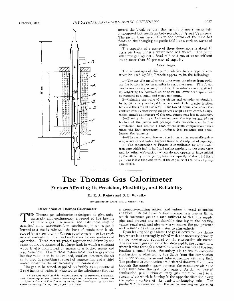
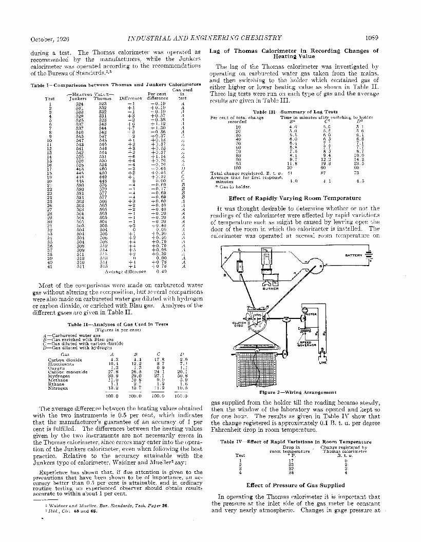
described as a continuous-flow calorimeter, in which gas is burned a t a steady rate and the heat of combustion is ab- sorbed by a stream of air flowing countercurrent, to the prod- ucts of combustion. Figures 1 and 2 show it's construction and operation. Three meters, geared together and driven by the same motor, are immersed in a large tank in which a constant water level is maintained by means of a bucket pump and weir over-flow. One of these meters measures the gas whose heating value is to be determined, another measures the air t o be used in absorbing the heat of combustion, and a third meter measures the air necessary for combustion.
The gas to be tesbed, supplied preferably a t 3, pressure of 3 to 6 inches of water, is admitted to the calorimeter through
1 Presented tinder the title "Factors Affecting the Precision, Flexibility, and Reliability of the Thomas Recording Gas Calorimeter" hefore the Division of Gas and Fuel Chemistry a t the 71st Meeting o f the American Chemical Society. T u l s a . Okla., April 5 to 9, 1926.
a pressure-reducing orifice, and enters a small expansion chamber. On the cover of this chamber is a bleeder flame, which consumes gas a t a rate sufficient to clear the supply pipe and prevent any considerable time lag in the heating values registered, and also serves to reduce the gas pressure on the inlet side of the gas meter to atmospheric.
Upon leaving the gas meter the gas is delivered to a cham- ber, where it is thoroughly mixed with the necessary primary air for combustion, supplied by the combustion air meter. The mixture of gas and air is then delivered to the burrier unit, where it rises through a central tube and is burned a t the top, forming a small flame. Secondary air to insure complete combustion is admitted to the flame from the combustion air meter through a second tube concentric with the first. The products of combustion are deflected downward and pay- through the annular space between the secondary air tube. arid a third tube, the heat iiiterchanger. -1s the products of combustion pass downward they give up their heat to a stream of air which is flowing in the opposite direction along the outqide surface of the heat-interchanging tube. The products of combustion and the heat-absorbing air travel in
Vol. 18, No. 10 1088 INDUSTRIAL AND E-VGINEERING CHEMISTRY
entirely separate ducts and are not mixed with one another. The transfer of heat from the products of combustion to the heat-absorbing air is so efficient that the products of combustion are discharged from the bottom of the burner unit a t a temperature very nearly that of the incoming heat- absorbing air. The water condensed from the products of combustion is removed by a drain leading to the water stor- age tank.
The meter supplying air to the burner unit for absorbing heat delivers it in a definite ratio with respect to the volume of gas supplied. An electrical resistance thermometer lo- cated near the outlet of this air meter gives the temperature of the heat-absorbing air as it enters the burner unit. The temperature of the heat-absorbing air after passing upwards
The use of air as the heat-absorbing medium makes it theo- retically possible to design a continuous-flow gas calorimeter whose indications would be independent of variations in temperature, barometric pressure, or meter speed, and would be a function only of the heating value of the gas. If the meters of the Thomas calorimeter were operating in a fluid having negligible vapor pressure, and if both the gas and the heat-absorbing air were free of water vapor, the temperature rise of the heat-absorbing air would be independent of meter speed, barometric pressure, or of the initial temperature of the heat-absorbing air, assuming the burner unit to have an efficiency of 100 per cent. This would be true because both the mass of combustible and the mass of heat-absorbing air delivered to the burner unit would be affected to exactly
* A 8 SUPPLY LINE n
Figure I-Arrangement of Piping and Meters in Tank Unit
through the heat interchanger, and after having absorbed the heat from the products of combustion, is measured by a second electrical resistance thermometer. The heat-ab- sorbing air is discharged a t the top of the burner unit.
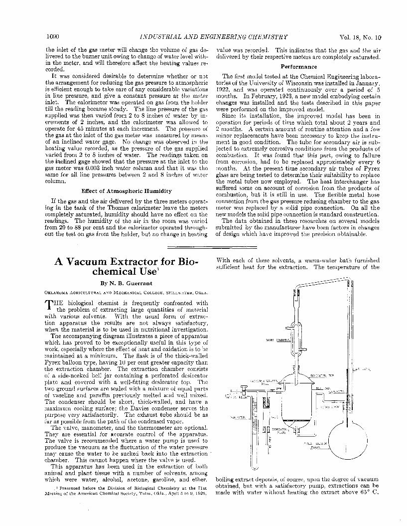
Figure 2 shows diagrammatically how the recording system operates. Two resistance thermometers, TI and Tz, one measuring the temperature of the heat-absorbing air delivered to the burner unit and the other measuring the temperature of the heat-absorbing air after being heated by the products of combustion, are in adjacent legs of a Wheatstone bridge. The recorder mechanism automatically keeps the bridge in balance by shifting the point of contact, S. The position of this point of contact when the bridge is balanced depends upon the temperature difference between the two resistance ther- mometers, which in turn depends upon the heating value of the gas being burned. That is, the higher the heating value of the gas the greater will be the difference in temperature and resistance between the thermometers located a t the inlet and the outlet for the heat absorbing air.
By making a graphical record of the positions of the points of contact, S, the Thomas calorimeter gives a continuous record of the total heating value of the gas supplied to the calorimeter, expressed in B. t. u. per cubic foot at standard conditions-namely, 60" F., a barometric pressure of 30 inches of mercury, and the gas saturated with water vapor. The reading indicated is always the total heating value of 1 cubic foot of gas a t standard conditions, irrespective of the actual barometric pressure or tank temperature.
the same extent by variations in meter speed, barometric pressure, and tank temperature. But the meters of the Thomas calorimeter operate in water, which has an appre- ciable vapor pressure, and the presence of water vapor in the gas and in the heat-absorbing air complicates the theory somewhat. It may be shown that under these conditions the temperature rise of the heat-absorbing air is not only a function of the heating value of the gas, but is dependent to a slight extent upon barometric pressure and to a more pro- nounced extent upon the initial temperature of the heat- absorbing air. However, the nickel wire selected for the resistance thermometers has a resistance-temperature re- lationship which compensates for these effects quite exactly. The manufacturers guarantee the instrument to be accurate within 1 per cent, irrespective of the barometric pressure and the tank temperature, provided the latter is between the limits 55" and 90" F.
Heating Value Comparisons between the Thomas and Junkers Calorimeters
At the present time the calorimeter of the Junkers type is accepted by the gas industry as the standard instrument for determining the heating value of gas. The results of a num- ber of comparisons between the Thomas and Junkers calo- rimeters are given in Table I. Both instruments were operated simultaneously on gas stored in a 65 cu. ft. gas holder, thereby avoiding uncertainties due to variations in heating value
October, 1926 ISDL’STRIAL A S D ESGISEERISG CHEXISTRY 1089
Test 1 2 3 4 5 6 7 8 9
10 11 12 13 14 15 16 17 .I8 19 20 2 1 22 23 24 25 26 27 28 29 30 3 1 32 33 34 35 36 37 38 39 40 41
Junkers 524 531 533 528 525 537 537 540 545 54 7 543 54 1 542 525 526 528 463 448 448 448 580 580 58 1 5s I 503 503 503 504 504 505 503 504 504 504 504 508 509 511 513 510 511
-HEATING VALUE- Thomas
523 532 532 531 523 543 544 543 547 54s 545 544 544 53 1 530 524 460 450 449 448 576
577 506 505 505 505 :05 004 505 504 505 506 508 512 514 513 313 314 515
J I I
during a test, The Thomas calorimeter was operated as recommended by the manufacturers, while the Junkers calorimeter was operated according to the recommendations of the Bureau of Stantiards.?~~
Lag of Thomas Calorimeter in Recording Changes of Heating Value
The lag of the Thomas calorimeter was investigated by operating on carbureted mater gas taken from the mains, and then switching to the holder which contained gas of either higher or lower heating value as shown in Table 11. Three lag tests were run on each type of gas and the average results are given in Table 111.
Table I-Comparisons between Thomas and Junkers Calorimeters Gas used
Per cent in Difference difference tect
- 1 -0.19 .A +I - 1 + 3 -2 +6 + 7 + 3 + 2 + 1 +2 + 3 + 2 -6 + 4 - 4 - 3 - 2 + I
0 - 4 -1 - 4 - 4 + 3 + 2 + 2 + 1 + 1 - 1 +1?-
0 +1 - 2 +4
-0 .19 - 0 . 1 9 + O . 57 - 0 . 3 s + 1 . 1 2 + 1 . 3 0 + 0 . 5 6 +0.37 +0.18 + 0 . 3 7 + O . 55 + O . 37 i 1 . 1 4 - 0 . 7 6 - 0 . 7 6 - 0 . 6 5 + 0 . 4 5 + 0 . 2 2
0 . 0 0 - 0 . 6 9 -0 .17 -0 .69 -0 .69 -0 .60 +0.40 -0.40 -0.20 -0.20 - 0 . 2 0 +0.40
0.00 + o . z o +o. i 9 -0.40
A .A A 4 A ’A A 1 .A ..I .A .-1 ..I .-t .t D C C C B B B B A .A A A .A .A A .A .I .A A i s +0.79 .A
+ 5 t 0 . 9 8 ‘A - 2 t o . 39 .4
0 0.00 .4 +4 + 0 . 7 8 A +4 + O . i 8 A
Average difference 0.49
Most of the comparisons were made on carbureted water gas without altering the composition, but several comparisons were also made on carbureted water gas diluted with hydrogen or carbon dioxide, or enriched with Blau gas. Analyses of the different gases are gil-en in Table 11.
Table 11---Analyses of Gas Used in Tests (Figures in per cent)
A-Carbureted water gas B-Gas enriched with Blau gas C-Gas diluted with carbon dioxide D-Gas diluted with hydrogen
Gas A B C D Carbon dioxide Illurninants Oxygen Carbon monoxide Hydrogen Methane Ethane Xitroren
4 . 3 1 0 . 4
1.3 2 7 . 8 3 0 . 9 11.0
1 . 1 13.2
4 . 4 1 2 . 2
1 . 3 2 6 . 5 29.0 1 0 . 8 2 . 1
1 3 . 7
17.8 8 . 7 0 . 9
2 4 . 1 2 7 . 1
9 . 0 1 . 2
1 1 . 2
2 . 9 7 . 1 1 . 1
20.1 50.8
5 . 9 1 . 6
1 0 . 5
100 0 100 0 100 0 100 0
The average difference between the heating values obtained with the two instruments is 0.5 per cent, which indicates that the manufacturer’s guarantee of an accuracy of 1 per cent is fulfilled. The differences between the heating values given by the two imtruments are not necessarily errors in the Thomas calorimeter, since errors may enter into the opera- tion of the Junkers calorimeter, even when following the best practice. Relative to the accuracy attainable with the Junkers type of calorimeter, Waidner and Mueller2 say:
Experience has shown that, if due attention is given to the precautions that have been shown to be of importance, an ac- curacy better than 0 ,5 per cent is attainable, and in ordinary routine testing an experienced observer should obtain results accurate to within about 1 per cent.
2 Waidner and ?dueller, Bur Standards, Tech. Paper 36 3 Ibrd , Crrc 48 and 65.
Table 111-Summary of Lag Tests
recorded Ba C a D a Per cent of total change Time in minutes after switching to holder
10 20 30 40 50 60 70 80 90 95
100
4 . 6 5 .0 5 . 5 6 . 0 6 . 4 6 . 8 7 . 5 8 . 1 9 . 7
1 1 . 8 30
5 .0 5 . 6 6 . 0 6 . 5 7 . 1 7 . 7 8 . 5 9 . 4
1 2 . 2 19.3 60
5 . 1 5 . 6 6 . 1 6 . 6 7 .1 7 . 7 8 . 7
10 .0 1 4 . 3 2 3 . 5 60
Total change registered, B t. u . 51 87 73 average time for first response,
minutes 4 0 4 1 4 5 a Gas in holder.
Effect of Rapidly Varying Room Temperature
It was thought desirable to determine whether or not the readings of the calorimeter were affected by rapid variations of temperature such as might be caused by leaving open the door of the room in which the calorimeter is installed. The calorimeter was operated a t normal room temperature on
LINE
Figure 2-Wiring Arrangement
gas supplied from the holder till the reading became steady, then the window of the laboratory was opened and kept so for one hour. The results as given in Table IV show that the change registered is approximately 0.1 B. t. u. per degree Fahrenheit drop in room temperature.
Table IV-Effect of Rapid Variations in Room Temperature Drop in Change registered by
room temperature Thomas calorimeter Test F. B. t. u. 1 17 0 2 23 2 3 32 3 4 34 4
Effect of Pressure of Gas Supplied
I n operating the Thomas calorimeter it is important that the pressure a t the inlet side of the gas meter be constant and very nearly atmospheric. Changes in gage pressure a t
1090 INDUSTRIAL A-VD ENGINEERI-VG CHEMISTRY Vol. 18, No. 10
the inlet of the gas meter Till change the volume of gas de- livered to the burner unit owing to change of water level with- in the meter, and will therefore affect the heating values re- corded.
It was considered desirable to determine whether or not the arrangement for reducing the gas pressure to atmospheric is efficient enough to take care of any considerable variations in line pressure, and give a constant pressure at the meter inlet. The calorimeter was operated on gas from the holder till the reading became steady. The line pressure of the gas supplied was then varied from 2 to 8 incheq of water by in- crements of 2 inches, and the calorimeter mas allowed to operate for 45 minutes a t each increment. The pressure of the gas a t the inlet of the gas meter was measured by means of an inclined water gage. h'o change was observed in the heating value recorded, as the pressure of the gas supplied varied from 2 to 8 inches of water. The readings taken on the inclined gage showed that the pressure a t the inlet to the gas meter was 0.003 inch water column and that it was the same for all line pressures between 2 and 8 inches of water column.
Effect of Atmospheric Humidity
If the gas and the air delivered by the three meters operat- ing in the tank of the Thomas calorimeter leave the meters completely saturated, humidity should have no effect on the readings. The humidity of the air in the room was varied from 29 to 88 per cent and the calorimeter operated through- out the test on gas from the holder, but no change in heating
value was recorded. This indicates that the gas and the air delivered by their respective meters are completely saturated.
Performance
The first model tested a t the Chemical Engineering labora- tories of the University of Wisconsin was installed in January, 1922, and was operated continuously over a period of 5 months. In February, 1923, a new model embodying certain changes was installed and the tests described in this paper were performed on the improved model.
Since its installation, the improved model has been in operation for periods of time which total about 2 years and 2 months. A certain amount of routine attention and a few minor replacements have been necessary to keep the instru- ment in good condition. The tube for secondary air is sub- jected to extremely corrosive conditions from the products of combustion. It was found that this part, owing to failure from corrosion, had to be replaced approximately every 6 months. At the present time secondary air tubes of Pyrex glass are being tested to determine their suitability to replace the metal tubes now employed. The heat interchanger has suffered some on account of corrosion from the products of combustion, but it is still in use. The flexible metal hose connection from the gas pressure reducing chamber to the gas meter was replaced by a solid pipe connection. On all t h e new models the solid pipe connection is standard construction.
The data obtained in these researches on several models submitted by the manufacturer have been factors in changes of design which have improved the precision obtainable.
With each of these solvents, a warm-water bath furnished sufficient heat for the extraction. The temperature of the A Vacuum Extractor for Bio-
chemical Use' By N. B. Guerrant
O K L A H O M A AGRICULTURAL AUD MECHANICAL C O L L E G E , S T I L L W A T E R , OKLA
HE biological chemist is frequently confronted with the problem of extracting large quantities of material
with various solvents. With the usual form of extrac- tion apparatus the results are not always satisfactory, when the material is to be used in nutritional investigation.
The accompanying diagram illustrates a piece of apparatus which has proved to be exceptionally useful in this type of work, especially where the effect of heat and oxidation is to be maintained at a minimum. The flask is of the thick-walled Pyrex balloon type, having 10 per cent greater capacity than the extraction chamber. The extraction chamber consists of a side-necked bell jar containing a perforated desiccator plate and covered with sb well-fitting desiccator top. The two ground surfaces are sealed with a mixture of equal parts of yaseline and paraffin previously melted and well mixed. The condenser should be shoit, thick-walled, and have a maximum cooling surface; the Davies condenser serves the purpose very satisfactorily. The exhaust tube should be as far as possible from the path of the condensed yapor.
The valve, manometer, and the thermometer are optional. They are essential for accurate control of the apparatus. The valve is recommended where a water pump is used to produce the vacuum as the fluctuation of the water pressure may cause the water to be sucked back into the extraction chamber.
This apparatus has been used in the extraction of both animal and plant tissue with a number of solvents, among n hich were water, alcohol, acetone, gasoline, and ether. boiling extract depends, of course, upon the degree of vacuum
nicetang of the ~ m e r i c a n Chemical society, Tulsa, Okla , .4prl1 j to g 19% made with water without heating the extract abol e 65" c.
This cannot happen where the valve is used.
1 presented before the Dlvlsion of Blologlcal Chemistry a t the 71st Obtained, but a pump> can be