Embed Size (px)
Citation preview
Keywords— Dynamic thermal performance, experimental measurements, lightweight timber frame structure, numerical modeling.
Abstract— The paper describes results of experimental and
numerical analysis of the thermal performance of lightweight timber frame structures (wall and roof) during the summer period. The aim of this research is to verify the suitability of numerical simulation methods for the prediction of the thermal performance of building structures. The measurements were taken on an experimental timber frame passive house of the VSB-TU Ostrava. The numerical modelling of the external structures is solved using the finite element method in the ANSYS software.
I. INTRODUCTION
The thermal performance of building structures influences users’ thermal comfort, the performance and energy consumption of heating, ventilation and air-conditioning devices. Light weight timber frame structures which do not have sufficient thermal capacity may cause problems to the optimal conception of the thermal load of the inside environment during the summer [1, 2]. The choice of suitable materials for the external walls may contribute to the elimination of the thermal load of the inside environment.
A comparison of results of experimental and numerical analysis of the thermal response of light weight timber frame structure during the summer period is the objective of this paper. The purpose of the research is verifying the suitability of the application of the numerical simulation method for the prediction of thermal performance of light-weight timber-based construction units.
Experimental measurements of temperature characteristics were run in a real timber frame passive house (Fig. 1) installed inside the premises of the Faculty of Civil Engineering at the Technical University of Ostrava. The passive house is utilized
This work was prepared from the funds of the Conceptual development of science, research and innovation for 2013 allocated to the VŠB-Technical University of Ostrava.
I. Skotnicová, is with the Faculty of Civil Engineering, VŠB-Technical University of Ostrava, 70800, Czech republic ((phone: 0420-597321957, e-mail: [email protected]).
L. Lausová is with the Faculty of Civil Engineering, VŠB-Technical University of Ostrava, 70800, Czech republic; e-mail: [email protected]).
P. Tymova is with the Faculty of Civil Engineering, VŠB-Technical University of Ostrava, 70800, Czech republic (e-mail: [email protected]).
Z. Galda is with the Faculty of Civil Engineering, VŠB-Technical University of Ostrava, 70800, Czech republic (e-mail: [email protected]).
as the Research and Innovation Centre of the Moravian-Silesian Wood Cluster and of the Faculty of Civil Engineering and is equipped with a number of measuring sensors monitoring not only temperature, but also humidity and other features and variables of the interior, building structures and the subsoil.
The numerical implicit method – the finite element method [3, 4, 5], more suitable for solution of non-stationary multidimensional thermal tasks than the analytic method, has been chosen for theoretical analysis of thermal performance of the external structure. The numerical simulation calculations
were performed, using the ANSYS software [6]. The external timber frame structures have been assessed in
two chosen details: 1) southern external wall, 2) roof structure.
Theoretical assessment of dynamic thermal performance of the external structures have been performed for summer boundary conditions obtained by experimental measurements (August 2013).
II. EXPRIMENTAL MEASUREMENT The timber-frame passive house has been designed as a two-
storeyed building without a basement with a single pitched roof of 15° slope. From the design point of view we are speaking about a lightweight timber prefabricated house.
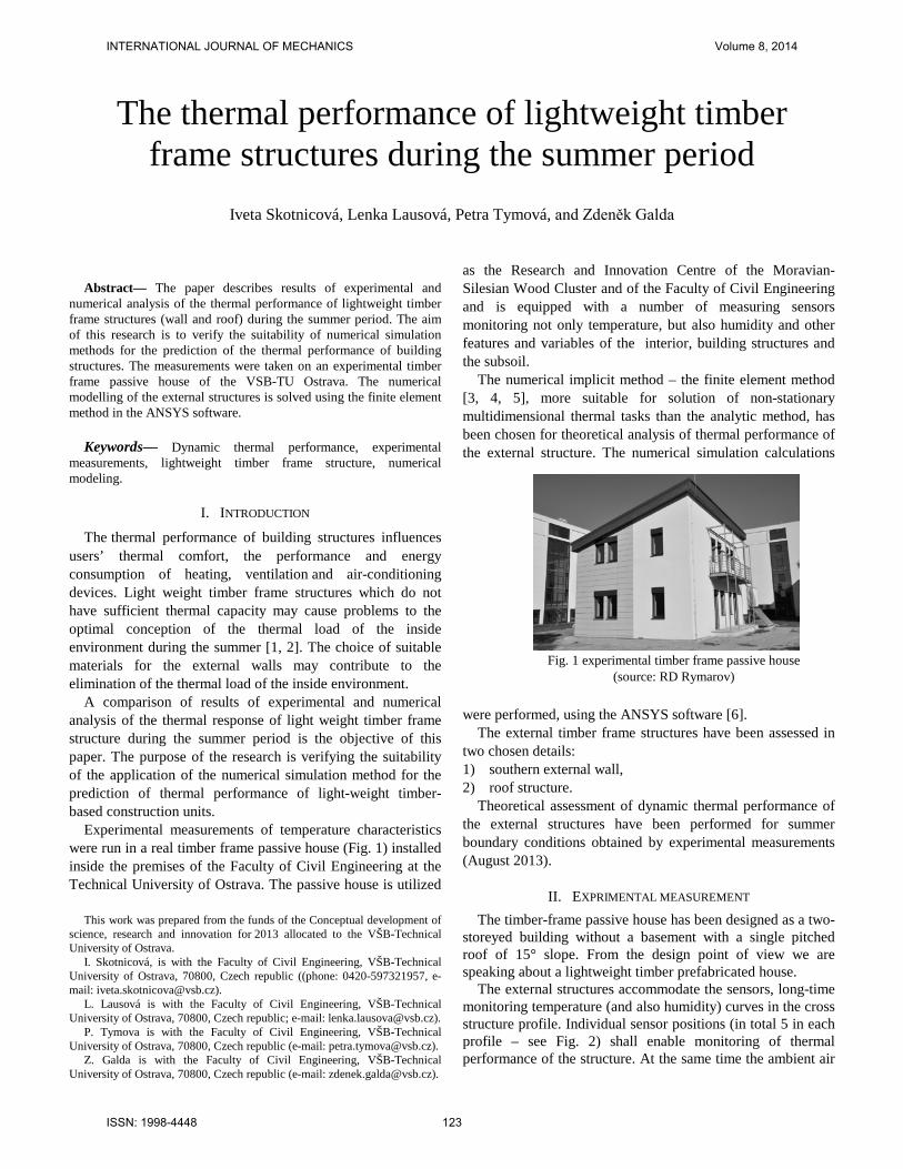
The external structures accommodate the sensors, long-time monitoring temperature (and also humidity) curves in the cross structure profile. Individual sensor positions (in total 5 in each profile – see Fig. 2) shall enable monitoring of thermal performance of the structure. At the same time the ambient air
The thermal performance of lightweight timber frame structures during the summer period
Iveta Skotnicová, Lenka Lausová, Petra Tymová, and Zdeněk Galda
Fig. 1 experimental timber frame passive house
(source: RD Rymarov)
INTERNATIONAL JOURNAL OF MECHANICS Volume 8, 2014
ISSN: 1998-4448 123
temperature is measured (shielded temperature sensor on the northern facade) as well as interior temperature. The measuring sensors have been installed inside the
structures during manufacture of structural components (Fig. 3).
The external structures are designed as diffusion open
structures with wood fibre thermal insulation (Steico). The Table I and Table II contain thermophysical properties of using building materials of the external wall and roof structure.
For the demonstration of temperature performance inside
the external wall and roof structure a typical summer month and day (August 2013) was chosen.
Fig. 4 and Fig. 5 show time dependent temperature curves during the month of August for the both structures.
Fig. 2 position of the temperature sensors inside of the external wall
Fig. 3 installation of temperature sensors into wall and roof components
Table II thermophysical properties of building materials of the roof structure
5101520253035404550
1.8.13 6.8.13 11.8.13 16.8.13 21.8.13 26.8.13 31.8.13
Time (days)
Tem
pera
ture
(°C
)
external surface (5) internal surface (1)temperature inside of structure (3) external air temperature
Fig. 4 measured temperatures inside the external wall (number means
sensor position)
Table I thermophysical properties of building materials of the external wall
5
15
25
35
45
55
1.8.13 6.8.13 11.8.13 16.8.13 21.8.13 26.8.13 31.8.13
Time (days)
Tem
pera
ture
(°C
)
external air temperature external surface (5)temperature inside of structure (3) internal surface (1)
Fig. 5 measured temperatures inside the roof structure (number means
sensor position)
INTERNATIONAL JOURNAL OF MECHANICS Volume 8, 2014
ISSN: 1998-4448 124
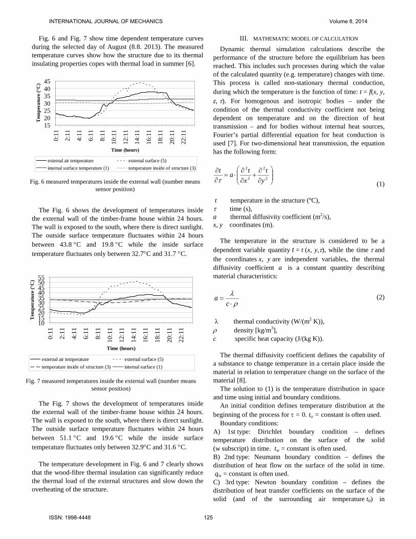
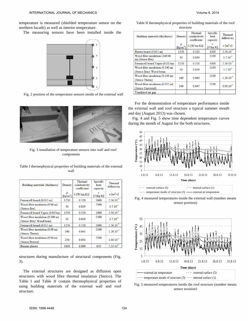
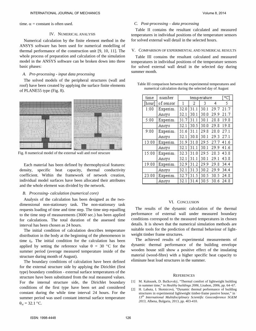
Fig. 6 and Fig. 7 show time dependent temperature curves during the selected day of August (8.8. 2013). The measured temperature curves show how the structure due to its thermal insulating properties copes with thermal load in summer [6].
The Fig. 6 shows the development of temperatures inside
the external wall of the timber-frame house within 24 hours. The wall is exposed to the south, where there is direct sunlight. The outside surface temperature fluctuates within 24 hours between 43.8 °C and 19.8 °C while the inside surface temperature fluctuates only between 32.7°C and 31.7 °C.
The Fig. 7 shows the development of temperatures inside the external wall of the timber-frame house within 24 hours. The wall is exposed to the south, where there is direct sunlight. The outside surface temperature fluctuates within 24 hours between 51.1 °C and 19.6 °C while the inside surface temperature fluctuates only between 32.9°C and 31.6 °C.
The temperature development in Fig. 6 and 7 clearly shows
that the wood-fibre thermal insulation can significantly reduce the thermal load of the external structures and slow down the overheating of the structure.
III. MATHEMATIC MODEL OF CALCULATION Dynamic thermal simulation calculations describe the
performance of the structure before the equilibrium has been reached. This includes such processes during which the value of the calculated quantity (e.g. temperature) changes with time. This process is called non-stationary thermal conduction, during which the temperature is the function of time: t = f(x, y, z, τ). For homogenous and isotropic bodies – under the condition of the thermal conductivity coefficient not being dependent on temperature and on the direction of heat transmission – and for bodies without internal heat sources, Fourier’s partial differential equation for heat conduction is used [7]. For two-dimensional heat transmission, the equation has the following form:
∂∂
+∂∂
⋅=∂∂
2
2
2
2
yt
xtat
τ (1) t temperature in the structure (ºC), τ time (s), a thermal diffusivity coefficient (m2/s), x, y coordinates (m).
The temperature in the structure is considered to be a dependent variable quantity t = t (x, y,τ), while the time τ and the coordinates x, y are independent variables, the thermal diffusivity coefficient a is a constant quantity describing material characteristics:
ρλ⋅
=c
a (2)
λ thermal conductivity (W/(m2 K)), ρ density [kg/m3], c specific heat capacity (J/(kg K)).
The thermal diffusivity coefficient defines the capability of a substance to change temperature in a certain place inside the material in relation to temperature change on the surface of the material [8].
The solution to (1) is the temperature distribution in space and time using initial and boundary conditions.
An initial condition defines temperature distribution at the beginning of the process for τ = 0. to = constant is often used.
Boundary conditions: A) 1st type: Dirichlet boundary condition – defines temperature distribution on the surface of the solid (w subscript) in time. tw = constant is often used. B) 2nd type: Neumann boundary condition – defines the distribution of heat flow on the surface of the solid in time. qw = constant is often used. C) 3rd type: Newton boundary condition – defines the distribution of heat transfer coefficients on the surface of the solid (and of the surrounding air temperature t0) in
15202530354045
0:11
2:11
4:11
6:11
8:11
10:1
1
12:1
1
14:1
1
16:1
1
18:1
1
20:1
1
22:1
1
Time (hours)
Tem
pera
ture
(°C
)
external air temperature external surface (5)internal surface temperature (1) temperature inside of structure (3)
Fig. 6 measured temperatures inside the external wall (number means
sensor position)
10152025303540455055
0:11
2:11
4:11
6:11
8:11
10:1
1
12:1
1
14:1
1
16:1
1
18:1
1
20:1
1
22:1
1
Time (hours)
Tem
pera
ture
(°C
)
external air temperature external surface (5)temperature inside of structure (3) internal surface (1)
Fig. 7 measured temperatures inside the external wall (number means
sensor position)
INTERNATIONAL JOURNAL OF MECHANICS Volume 8, 2014
ISSN: 1998-4448 125
time. α = constant is often used.
IV. NUMERICAL ANALYSIS Numerical calculation by the finite element method in the
ANSYS software has been used for numerical modelling of thermal performance of the construction unit [9, 10, 11]. The whole process of preparation and calculation of the simulation model in the ANSYS software can be broken down into three basic phases:
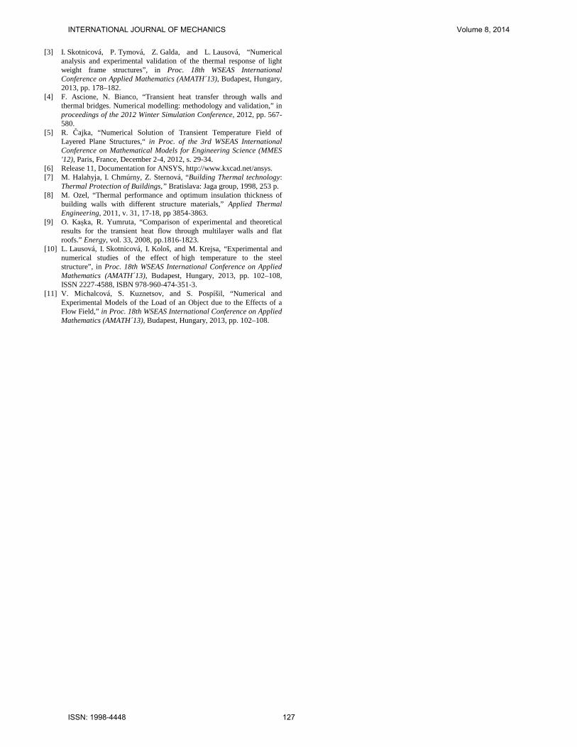
A. Pre-processing - input data processing The solved models of the peripheral structures (wall and
roof) have been created by applying the surface finite elements of PLANE55 type (Fig. 8).
Each material has been defined by thermophysical features: density, specific heat capacity, thermal conductivity coefficient. Within the framework of network creation, individual model surfaces have been allocated their attributes and the whole element was divided by the network.
B. Processing- calculation (numerical core) Analysis of the calculation has been designed as the two-
dimensional non-stationary task. The non-stationary task requests loading of time and time step. The time step equalling to the time step of measurements (3600 sec.) has been applied for calculations. The total duration of the assessed time interval has been chosen as 24 hours.
The initial condition of calculation describes temperature distribution in the body at the beginning of the phenomenon in time t0. The initial condition for the calculation has been applied by setting the reference value θ = 30 °C for the summer period (average measured temperature inside of the structure during month of August).
The boundary conditions of calculation have been defined for the external structure side by applying the Dirichlet (first type) boundary condition - external surface temperatures of the structure have been substituted from the real measured values. For the internal structure side, the Dirichlet boundary conditions of the first type have been set and considered constant during the while time interval 24 hours. For the summer period was used constant internal surface temperature θsi = 32.1 °C.
C. Post-processing – data processing Table II contains the resultant calculated and measured
temperatures in individual positions of the temperature sensors for solved external wall detail in the selected hours.
V. COMPARISON OF EXPERIMENTAL AND NUMERICAL RESULTS Table III contains the resultant calculated and measured
temperatures in individual positions of the temperature sensors for solved external wall detail in the selected day during summer month.
VI. CONCLUSION The results of the dynamic calculation of the thermal
performance of external wall under measured boundary conditions correspond to the measured temperatures in chosen details. It is shown that the numerical simulation methods are suitable tools for the prediction of thermal behaviour of light-weight timber frame structures.
The achieved results of experimental measurements of dynamic thermal performance of the building envelope wooden house still show a positive effect of the insulating material (wood-fibre) with a higher specific heat capacity to eliminate heat load structures in the summer.
REFERENCES [1] M. Kalousek, D. Bečkovský, “Thermal comfort of lightweight building
in summer time,” in Healthy buildings 2006, Lisabon, 2006, pp. 64–67. [2] H. Lahuta, I. Skotnicová, “Dynamic thermal performance of building
structures in experimental lightweight timber-frame passive house,” in . 13th International Multidisciplinary Scientific Geoconference SGEM 2013, Albena, Bulgaria, 2013, pp. 403-410.
Fig. 8 numerical model of the external wall and roof strucure
Table III comparison between the experimental temperatures and
numerical calculation during the selected day of August
INTERNATIONAL JOURNAL OF MECHANICS Volume 8, 2014
ISSN: 1998-4448 126
[3] I. Skotnicová, P. Tymová, Z. Galda, and L. Lausová, “Numerical analysis and experimental validation of the thermal response of light weight frame structures”, in Proc. 18th WSEAS International Conference on Applied Mathematics (AMATH´13), Budapest, Hungary, 2013, pp. 178–182.
[4] F. Ascione, N. Bianco, “Transient heat transfer through walls and thermal bridges. Numerical modelling: methodology and validation,” in proceedings of the 2012 Winter Simulation Conference, 2012, pp. 567-580.
[5] R. Čajka, “Numerical Solution of Transient Temperature Field of Layered Plane Structures,“ in Proc. of the 3rd WSEAS International Conference on Mathematical Models for Engineering Science (MMES '12), Paris, France, December 2-4, 2012, s. 29-34.
[6] Release 11, Documentation for ANSYS, http://www.kxcad.net/ansys. [7] M. Halahyja, I. Chmúrny, Z. Sternová, “Building Thermal technology:
Thermal Protection of Buildings,” Bratislava: Jaga group, 1998, 253 p. [8] M. Ozel, “Thermal performance and optimum insulation thickness of
building walls with different structure materials,” Applied Thermal Engineering, 2011, v. 31, 17-18, pp 3854-3863.
[9] O. Kaşka, R. Yumruta, “Comparison of experimental and theoretical results for the transient heat flow through multilayer walls and flat roofs.” Energy, vol. 33, 2008, pp.1816-1823.
[10] L. Lausová, I. Skotnicová, I. Kološ, and M. Krejsa, “Experimental and numerical studies of the effect of high temperature to the steel structure”, in Proc. 18th WSEAS International Conference on Applied Mathematics (AMATH´13), Budapest, Hungary, 2013, pp. 102–108, ISSN 2227-4588, ISBN 978-960-474-351-3.
[11] V. Michalcová, S. Kuznetsov, and S. Pospíšil, “Numerical and Experimental Models of the Load of an Object due to the Effects of a Flow Field,” in Proc. 18th WSEAS International Conference on Applied Mathematics (AMATH´13), Budapest, Hungary, 2013, pp. 102–108.
INTERNATIONAL JOURNAL OF MECHANICS Volume 8, 2014
ISSN: 1998-4448 127