Embed Size (px)
Citation preview

Department of Mechanical and Aerospace Engineering
The Thermal Analysis of a Flooded Absorber Type Solar Collector for Low Temperature Application
Author: Chris Thom
Supervisor: Dr. Daniel Cóstola
A Thesis submitted for the partial fulfilment for the requirement of the degree
Master of Science
Sustainable Engineering: Renewable Energy Systems and the Environment
2018

The Thermal Analysis of a Flooded Absorber Type Solar Collector for Low Temperature Application
University of Strathclyde, MAE 2
Abstract
In this study, the design and simulation of a flooded absorber type solar collector is
developed and analysed for the production of low temperature water for domestic use.
Design objectives include water production bounds of 40oC – 60oC and simplicity of design.
Through the literature, a base model is formed, using the design principles of a parallel tube
FPC. The performance characteristics are determined within simulation environment
software ESP-r. In the simulation software, various aspects of the FAC are altered to ensure
optimal design. The final model FAC design results are produced. An overall system
efficiency is found at 37.5% which is deemed acceptable within the simplicity of design.

The Thermal Analysis of a Flooded Absorber Type Solar Collector for Low Temperature Application
University of Strathclyde, MAE 3
Acknowledgments
I would like to thank Dr Daniel Cóstola for seeing me at very short notice on several
occasions after my initial topic change and for giving me guidance throughout the three
months. I would also like to thank Dr Jon Hand who provided guidance in installing ESP-r
software onto my Mac, which proved to be very important. I would also like to thank
Graeme Flett who answered to many of my emails about my ESP-r model that should have
been sent to my supervisor. Last but not least, to Strathclyde Business School where I
worked and to the security team who always kept me company late into the night.
The Thermal Analysis of a Flooded Absorber Type Solar Collector for Low Temperature Application
University of Strathclyde, MAE 4
Table of Contents
Abstract ................................................................................................................................ 2
Acknowledgments ................................................................................................................ 3
List of Figures ....................................................................................................................... 6
List of Tables ......................................................................................................................... 7
Nomenclature ....................................................................................................................... 8
Acronyms .............................................................................................................................. 9
1. Introduction ................................................................................................................ 10
1.1 Solar Resource................................................................................................................ 10 1.1.1 System Types - Background ..................................................................................................... 11
1.2 Project Motivation ......................................................................................................... 13
1.3 Project Aim..................................................................................................................... 14
1.4 Project Methodology...................................................................................................... 15
1.5 Scope .............................................................................................................................. 15
1.6 ESP-r ............................................................................................................................... 15
2. Literature Review ....................................................................................................... 16
2.1 Introduction ................................................................................................................... 16
2.2 Solar Collector System.................................................................................................... 16 2.2.1 Previous Solar Thermal Systems .............................................................................................. 16
2.3 The Flat Plate Collector .................................................................................................. 19 2.3.1 Absorber Modifications ........................................................................................................... 21 2.3.2 Absorber Efficiencies ............................................................................................................... 24 2.3.3 Alternate Designs .................................................................................................................... 25 2.3.4 Enhancement Devices ............................................................................................................. 25 2.3.5 Glazing .................................................................................................................................... 26 2.3.6 Optimum Tilt ........................................................................................................................... 28 2.3.7 Heat Loss Reduction ................................................................................................................ 31
2.4 Application of Flat Plate Collectors ................................................................................ 33 2.4.1 Desalination ............................................................................................................................ 33 2.4.2 Domestic Hot Water................................................................................................................ 34
2.5 Calculation ..................................................................................................................... 35 2.5.1 Efficiency Calculation .............................................................................................................. 35
2.6 Conclusion ...................................................................................................................... 37
3. Design Considerations ................................................................................................ 37
3.1 Orientation & Inclination ............................................................................................... 37
3.2 Collector Materials ......................................................................................................... 39
3.3 Thermal Expansion ......................................................................................................... 40
3.4 Stagnation Temperature ................................................................................................ 40
4. FAC Design .................................................................................................................. 41
The Thermal Analysis of a Flooded Absorber Type Solar Collector for Low Temperature Application
University of Strathclyde, MAE 5
5. Model Description ...................................................................................................... 42
5.1 Introduction ................................................................................................................... 42
5.2 Base Model .................................................................................................................... 42
5.3 Surface Attributes .......................................................................................................... 44 5.3.1 Insulation ................................................................................................................................ 44 5.3.2 Absorption .............................................................................................................................. 45 5.3.3 Glazing .................................................................................................................................... 45 5.3.4 Thermal Storage...................................................................................................................... 45
5.4 Thermal Zones ................................................................................................................ 47 5.4.1 Casing ..................................................................................................................................... 47 5.4.2 Absorber Plates ....................................................................................................................... 48 5.4.3 Environment ........................................................................................................................... 49
5.5 Network Flow ................................................................................................................. 49 5.5.1 Water Network ....................................................................................................................... 50 5.5.2 Air Network ............................................................................................................................ 51 5.5.3 Control System........................................................................................................................ 52 5.5.4 Connections ............................................................................................................................ 53
6. Results ........................................................................................................................ 54
6.1 Climate ........................................................................................................................... 54 6.1.1 Seasonal Performance ............................................................................................................. 54
6.2 Modifications to Base Model ......................................................................................... 58
6.3 Design Objective ............................................................................................................ 58
6.4 Base Model .................................................................................................................... 58 6.4.1 Temperature Distribution ........................................................................................................ 58 6.4.2 Stagnation Temperature ......................................................................................................... 59
6.5 Modifications to Base Model ......................................................................................... 60 6.5.1 Flowrate and Tank Size ............................................................................................................ 60 6.5.2 Glazing .................................................................................................................................... 64 6.5.3 Absorber Plate Spacing............................................................................................................ 67 6.5.4 Insulation ................................................................................................................................ 69
6.6 Final Model .................................................................................................................... 71
6.7 System Efficiency Model ................................................................................................ 72 6.7.1 Calculation .............................................................................................................................. 74
7. Final Discussion ........................................................................................................... 77
8. Conclusion................................................................................................................... 79
9. Future Work ................................................................................................................ 80
10. References .............................................................................................................. 80
11. Appendices .............................................................................................................. 86
Appendix A: Base Model Supplementary Data ........................................................................... 86
Appendix B: Final Model Supplementary Data ........................................................................... 88
The Thermal Analysis of a Flooded Absorber Type Solar Collector for Low Temperature Application
University of Strathclyde, MAE 6
List of Figures FIGURE 1 - EXISTING SOLAR HOT WATER HEATING CAPACITY. TOP 10 REGIONS/COUNTRIES (2010) (RAISUL
ISLAM, SUMATHY, & ULLAH KHAN, 2013) 10 FIGURE 2 – LAYOUT OF A CONVENTIONAL SOLAR HOT WATER SYSTEM (JAMAR, MAJID, AZMI, NORHAFANA, &
RAZAK, 2016) 11 FIGURE 3 – LAYOUT OF A "THERMOSIPHON" SWH SYSTEM (JAMAR ET AL., 2016) 12 FIGURE 4 - THE CLIMAX SOLAR WATER HEATER ADVERTISEMENT 17 FIGURE 5 - CONFIGURATION OF A FLAT PLATE SOLAR COLLECTOR: (A) CROSS-SECTIONAL (B) ISOMETRIC 20 FIGURE 6 - DESIGNS OF VARIOUS FLUID PASSAGEWAYS WITHIN ABSORBERS (LENEL, 1984) 22 FIGURE 7 - SOLAR ANGLES 29 FIGURE 8 - INCLINATION AND ORIENTATION ANGLES (FIREBIRD,2011) 38 FIGURE 9 - OPTIMUM TILT ANGLE 38 FIGURE 10 - EXPLODED VIEW, FLOODED ABSORBER SOLAR COLLECTOR WITH MAJOR DIMENSIONS 41 FIGURE 11 - FULL ESP-R MODEL LAYOUT 43 FIGURE 12 - CONTROL ACTION OF COLLECTOR – TANK PUMP 53 FIGURE 13 - ARBITRARY 5-DAY PERIOD IN WINTER (GLASGOW) 55 FIGURE 14 - ARBITRARY 5-DAY PERIOD IN SPRING (GLASGOW) 55 FIGURE 15 - ARBITRARY 5-DAY PERIOD IN SUMMER (GLASGOW) 56 FIGURE 16 - ARBITRARY 5 DAY PERIOD IN AUTUMN (GLASGOW) 56 FIGURE 17 - TEMPERATURE DISTRIBUTION ACROSS ABSORBER PLATE WITH VARYING SURFACE CONVECTION 59 FIGURE 18 - STAGNATION TEMPERATURE OF MID ABSORBER 60 FIGURE 19 - WATER TEMPERATURE GAIN FOR VARIOUS FLOWRATES (152L) 61 FIGURE 20 - WATER TEMPERATURE GAIN FOR VARIOUS FLOWRATES (206L) 61 FIGURE 21 - WATER TEMPERATURE GAIN FOR VARIOUS FLOWRATES (369L) 62 FIGURE 22 - MASS FLOW: 0.1KG/S TANK VOLUME: 369L 64 FIGURE 23 - EFFECTS OF GLAZING LAYERS ON TANK & ABSORBER TEMPERATURE - SUMMER 65 FIGURE 24 - EFFECTS OF GLAZING LAYERS ON TANK & ABSORBER TEMPERATURE – WINTER 67 FIGURE 25 - EFFECTS OF PLATE SPACING WITH ABSORBER TEMPERATURE 68 FIGURE 26 - EFFECTS OF WATER TEMPERATURE GAIN WITH PLATE SPACING 68 FIGURE 27 - EFFECTS OF INSULATION ON WATER TEMPERATURE ACHIEVED 71 FIGURE 28 - ABSORBER TEMPERATURE & INCIDENT SOLAR RADIATION (SIMULATION PERIOD - DAY 1) 72 FIGURE 29 - ABSORBER TEMPERATURE & INCIDENT SOLAR RADIATION (SIMULATION PERIOD - DAY 2) 73 FIGURE 30 - ABSORBER TEMPERATURE & INCIDENT SOLAR RADIATION (SIMULATION PERIOD - DAY 5) 73 FIGURE 32 - ABSORBED CONVECTION IN GLAZING SURFACE (WINTER0 86 FIGURE 33 - ABSORBED CONVECTION IN GLAZING SURFACE (SPRING) 87 FIGURE 34 - ABSORBED CONVECTION IN GLAZING SURFACE (SUMMER) 87 FIGURE 35 - ABSORBED CONVECTION IN GLAZING SURFACE (AUTUMN) 88 FIGURE 36 - AMBIENT TEMPERATURE AND WATER TANK TEMPERATURE GAIN FOR FINAL MODEL 88 FIGURE 37 - TOTAL DIRECT NORMAL SOLAR FLUX ON COLLECTOR CASING FOR FINAL MODEL 89

The Thermal Analysis of a Flooded Absorber Type Solar Collector for Low Temperature Application
University of Strathclyde, MAE 7
List of Tables TABLE 1 - COMMONLY USED SELECTIVE COATINGS (G. D., 1987) 23 TABLE 2 - BASE MODEL INSULATION 44 TABLE 3 - BASE MODEL ABSORBER MATERIAL 45 TABLE 4 - BASE MODEL GLAZING 45 TABLE 5 - BASE MODEL TANK INSULATION 46 TABLE 6 - THERMAL ZONES 47 TABLE 7 - CASING ZONE CONSTRUCTION 48 TABLE 8 - ABSORBER PLATE CONSTRUCTION 49 TABLE 9 - ESP-R MODEL CONNECTIONS 54 TABLE 10 - CONSTRUCTION DETAILS OF GLAZING MATERIALS 65 TABLE 11 - INSULATION LAYERS FOR TESTING 70 TABLE 12 - VARIABLES FOR EFFICIENCY CALCULATION 76 TABLE 13 - CALCULATED SYSTEM ENERGY & EFFICIENCY 76
The Thermal Analysis of a Flooded Absorber Type Solar Collector for Low Temperature Application
University of Strathclyde, MAE 8
Nomenclature
𝑄"#$ = 𝐷𝑎𝑖𝑙𝑦𝑡𝑜𝑡𝑎𝑙𝑛𝑒𝑡𝑒𝑛𝑒𝑟𝑔𝑦𝑎𝑏𝑠𝑜𝑟𝑏𝑡𝑖𝑜𝑛 4𝑀𝐽𝑑𝑎𝑦
8
𝑄9 = 𝐷𝑎𝑖𝑙𝑦𝑡𝑜𝑡𝑎𝑙𝑒𝑛𝑒𝑟𝑔𝑦𝑎𝑏𝑠𝑜𝑟𝑏𝑡𝑖𝑜𝑛 4𝑀𝐽𝑑𝑎𝑦
8
𝑄:;<< = 𝐷𝑎𝑖𝑙𝑦𝑡𝑜𝑡𝑎𝑙𝑒𝑛𝑒𝑟𝑔𝑦𝑙𝑜𝑠𝑠 4𝑀𝐽𝑑𝑎𝑦
8
𝑀 = 𝑇𝑜𝑡𝑎𝑙𝑚𝑎𝑠𝑠𝑜𝑓𝑤𝑎𝑡𝑒𝑟𝑖𝑛𝑠𝑦𝑠𝑡𝑒𝑚(𝑘𝑔)
𝐶E = 𝐻𝑒𝑎𝑡𝑐𝑎𝑝𝑎𝑐𝑖𝑡𝑦𝑜𝑓𝑤𝑎𝑡𝑒𝑟 4𝑀𝐽𝑘𝑔;𝐶
8
𝑇I = 𝐹𝑖𝑛𝑎𝑙𝑡𝑎𝑛𝑘𝑡𝑒𝑚𝑝𝑒𝑟𝑎𝑡𝑢𝑟𝑒(;𝐶) 𝑇L = 𝐼𝑛𝑖𝑡𝑖𝑎𝑙𝑡𝑎𝑛𝑘𝑡𝑒𝑚𝑝𝑒𝑟𝑎𝑡𝑢𝑟𝑒(;𝐶) 𝛼# = 𝐸𝑓𝑓𝑒𝑐𝑡𝑖𝑣𝑒𝑠𝑜𝑙𝑎𝑟𝑎𝑏𝑠𝑜𝑟𝑏𝑎𝑛𝑐𝑒(𝑑𝑖𝑚𝑒𝑛𝑠𝑖𝑜𝑛𝑙𝑒𝑠𝑠) 𝐴9 = 𝑇𝑜𝑡𝑎𝑙𝑐𝑜𝑙𝑙𝑒𝑐𝑡𝑜𝑟𝑎𝑟𝑒𝑎(𝑚R)
𝐻$ = 𝐷𝑎𝑖𝑙𝑦𝑡𝑜𝑡𝑎𝑙𝑠𝑜𝑙𝑎𝑟𝑖𝑟𝑟𝑎𝑑𝑖𝑎𝑡𝑖𝑜𝑛𝑖𝑛𝑐𝑖𝑑𝑒𝑛𝑡𝑢𝑝𝑜𝑛𝑐𝑜𝑙𝑙𝑒𝑐𝑡𝑜𝑟𝑠𝑢𝑟𝑓𝑎𝑐𝑒 4𝑀𝐽𝑚R8
𝑡I = 𝐹𝑖𝑛𝑎𝑙𝑡𝑖𝑚𝑒𝑜𝑓𝑒𝑛𝑒𝑟𝑔𝑦𝑐𝑜𝑙𝑙𝑒𝑐𝑡𝑖𝑛𝑔𝑝ℎ𝑎𝑠𝑒(ℎ𝑜𝑢𝑟) 𝑡L = 𝐼𝑛𝑖𝑡𝑖𝑎𝑙𝑡𝑖𝑚𝑒𝑜𝑓𝑒𝑛𝑒𝑟𝑔𝑦𝑐𝑜𝑙𝑙𝑒𝑐𝑡𝑖𝑛𝑔𝑝ℎ𝑎𝑠𝑒(ℎ𝑜𝑢𝑟)
𝐼T = 𝐼𝑛𝑐𝑖𝑑𝑒𝑛𝑡𝑠𝑜𝑙𝑎𝑟𝑟𝑎𝑑𝑖𝑎𝑡𝑖𝑜𝑛𝑜𝑛𝑐𝑜𝑙𝑙𝑒𝑐𝑡𝑜𝑟𝑠𝑢𝑟𝑓𝑎𝑐𝑒 4𝑊𝑚R8
𝑈$ = 𝑂𝑣𝑒𝑟𝑎𝑙𝑙ℎ𝑒𝑎𝑡𝑙𝑜𝑠𝑠𝑐𝑜𝑒𝑓𝑓𝑖𝑐𝑒𝑛𝑡(𝑀𝐽/;𝐶) 𝑇Y = 𝐷𝑎𝑖𝑙𝑦𝑎𝑣𝑒𝑟𝑎𝑔𝑒𝑡𝑎𝑛𝑘𝑡𝑒𝑚𝑝𝑒𝑟𝑎𝑡𝑢𝑟𝑒(;𝐶) 𝑇YZ = 𝐷𝑎𝑖𝑙𝑦𝑎𝑣𝑒𝑟𝑎𝑔𝑒𝑎𝑚𝑏𝑖𝑒𝑛𝑡𝑡𝑒𝑚𝑝𝑒𝑟𝑎𝑡𝑢𝑟𝑒(;𝐶)
𝑞"#$ = 𝐷𝑎𝑖𝑙𝑦𝑡𝑜𝑡𝑎𝑙𝑛𝑒𝑡𝑒𝑛𝑒𝑟𝑔𝑦𝑎𝑏𝑠𝑜𝑟𝑏𝑡𝑖𝑜𝑛𝑝𝑒𝑟𝑐𝑜𝑙𝑙𝑒𝑐𝑡𝑜𝑟𝑎𝑟𝑒𝑎 4𝑀𝐽
𝑚R𝑑𝑎𝑦8
𝑈< = 𝑂𝑣𝑒𝑟𝑎𝑙𝑙𝑠𝑦𝑠𝑡𝑒𝑚𝑙𝑜𝑠𝑠𝑟𝑎𝑡𝑒 4𝑀𝐽𝑚R;𝐶
8
𝜂< = 𝐷𝑎𝑖𝑙𝑦𝑆𝑦𝑠𝑡𝑒𝑚𝑒𝑓𝑓𝑖𝑐𝑒𝑛𝑐𝑦(%) 𝜂T = 𝑂𝑣𝑒𝑟𝑎𝑙𝑙𝑆𝑦𝑠𝑡𝑒𝑚𝑒𝑓𝑓𝑖𝑐𝑒𝑛𝑐𝑦(%)

The Thermal Analysis of a Flooded Absorber Type Solar Collector for Low Temperature Application
University of Strathclyde, MAE 9
Acronyms FAC – Flooded Absorber Solar Collector
FPC – Flat Plate Solar Collector
STC – Solar Thermal Collector
EU – European Union
DHW – Domestic Hot Water
ST – Solar Thermal
PV – Photovoltaic
SWH – Solar Water Heater
ETFE – Ethylene Tetra Fluro Ethylene
CLTE – Coefficient of Linear Thermal Expansion
GWth – GigaWatt thermal
The Thermal Analysis of a Flooded Absorber Type Solar Collector for Low Temperature Application
University of Strathclyde, MAE 10
1. Introduction
1.1 Solar Resource
Solar Energy is the primary light and heat resource of the earth. In the modern day, there are
two major ways in which to utilise solar resource, for heat and for electricity. The most
common is for electricity production. Photovoltaic materials convert radiation from the sun
into electricity due to a phenomenon known as the photoelectric effect. These materials have
the ability to absorb photons of light and release electrons, creating an electrical current. Big
players in the market include China, USA, Japan and Italy.
The other major resource is the suns thermal energy. One of the most widely
recognised solar thermal application is solar water hearting. Solar water heaters are typical
devices that absorbs the solar thermal energy and use it to directly heat a transfer fluid
(Chong, Chay, & Chin, 2012) . Technological viability of solar thermal systems has long been
recognised and is employed in many domestic and commercial sectors worldwide.
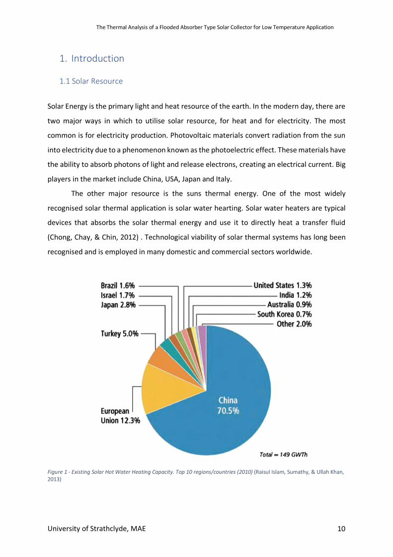
Figure 1 - Existing Solar Hot Water Heating Capacity. Top 10 regions/countries (2010) (Raisul Islam, Sumathy, & Ullah Khan, 2013)
The Thermal Analysis of a Flooded Absorber Type Solar Collector for Low Temperature Application
University of Strathclyde, MAE 11
In Figure 1 above, the share of the thermal market in 2010 was owned by China at
70.5%, followed by Europe at 12.35. Four years later in 2014, the installed capacity of thermal
collectors worldwide was at 410.2GWth. (Mauthner, Weiss, & Spörk-Dür, 2014). This figure
corresponds to roughly 586 million square meters of collector area in operation across the
globe. In the present thermal energy market, China leads, with 289.5GWth. Europe is still a
large distance behind at 47.5GWth. Together, this makes up 82.1% of the worldwide market.
Countries in areas such as Sub-Saharan Africa and MENA which have ample solar resource,
have a total installed capacity of less than 10GWth between them. This could be blamed on
the fact that current solar collectors are relatively expensive to design and require complex
procedures to build them.
In 2014, the breakdown of cumulated capacity in operation was 71.2% evacuated tube
collectors, 22.1% glazed flat plate collectors and 6.3% unglazed water collectors. These
systems are classed as “Active” or “Passive” systems. (Mordor Intelligence, 2017) Of these
systems, they are classed as high temperature or low temperature. High temperature systems
tend to be associated with industrial applications. Low temperature thermal solar collectors
are those which produce heat, mainly for domestic use, from 40oC – 60oC (Solar Energy, 2015)
1.1.1 System Types - Background
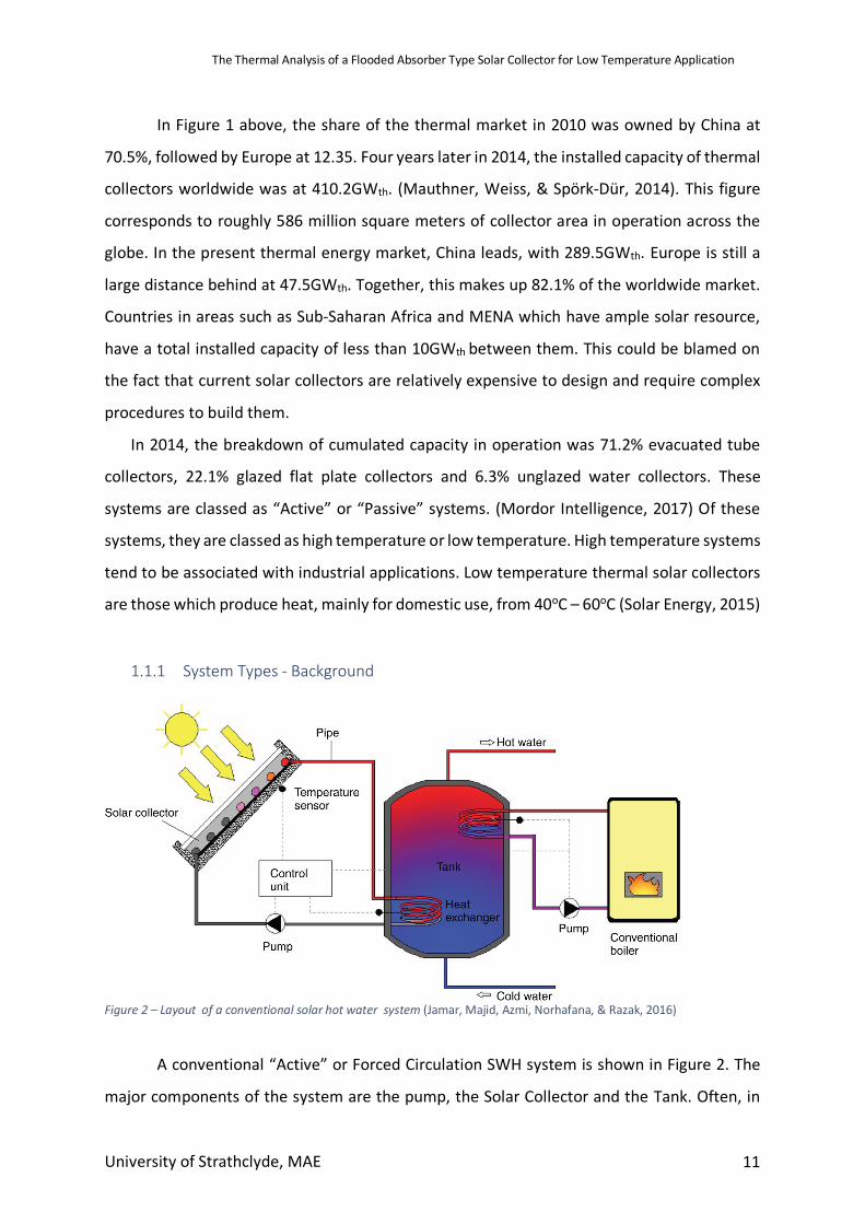
Figure 2 – Layout of a conventional solar hot water system (Jamar, Majid, Azmi, Norhafana, & Razak, 2016)
A conventional “Active” or Forced Circulation SWH system is shown in Figure 2. The
major components of the system are the pump, the Solar Collector and the Tank. Often, in
The Thermal Analysis of a Flooded Absorber Type Solar Collector for Low Temperature Application
University of Strathclyde, MAE 12
conventional systems, the collectors are backed up with an externally powered boiler to
ensure hot water can be supplied in times when solar energy is not available. The active
system uses electrical pumps, valves and controllers to circulate water through the collector
(Jamar et al., 2016). Preferably, in these systems, the storage tank is located below the
collector to reduce the pump work, although this is not essential (Yeh & Chen, 1985). Active
systems can be open or closed loop forced circulation type. In the case of domestic water,
open loop (direct) active systems transfer thermal energy directly to the actual water the
household will be using. The water is heated and then pumped into storage for use in the
home. A closed loop (indirect) active system heats a separate heat transfer medium from the
household water. This heat transfer fluid (sometimes anti-freeze) is heated in the collector
and then pumped into a storage tank where a heat exchanger transfers heat from the fluid to
the household water (Patel, Pragna Patel, & Patel, 2012)
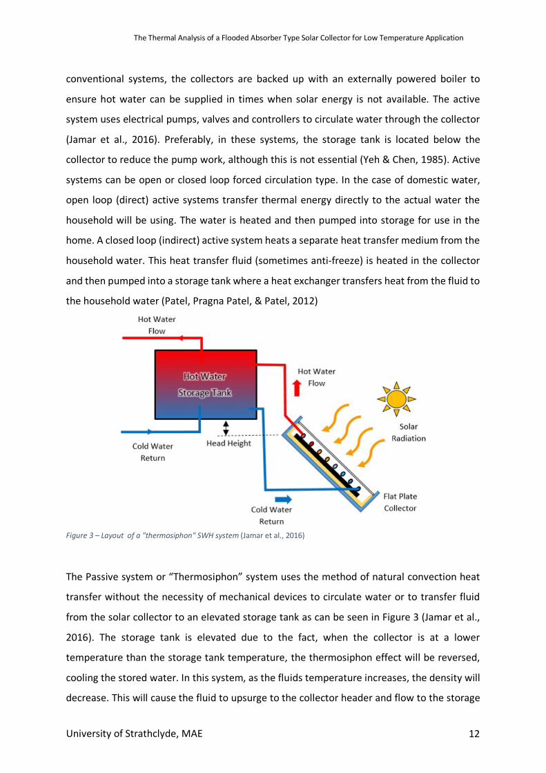
Figure 3 – Layout of a "thermosiphon" SWH system (Jamar et al., 2016)
The Passive system or “Thermosiphon” system uses the method of natural convection heat
transfer without the necessity of mechanical devices to circulate water or to transfer fluid
from the solar collector to an elevated storage tank as can be seen in Figure 3 (Jamar et al.,
2016). The storage tank is elevated due to the fact, when the collector is at a lower
temperature than the storage tank temperature, the thermosiphon effect will be reversed,
cooling the stored water. In this system, as the fluids temperature increases, the density will
decrease. This will cause the fluid to upsurge to the collector header and flow to the storage
The Thermal Analysis of a Flooded Absorber Type Solar Collector for Low Temperature Application
University of Strathclyde, MAE 13
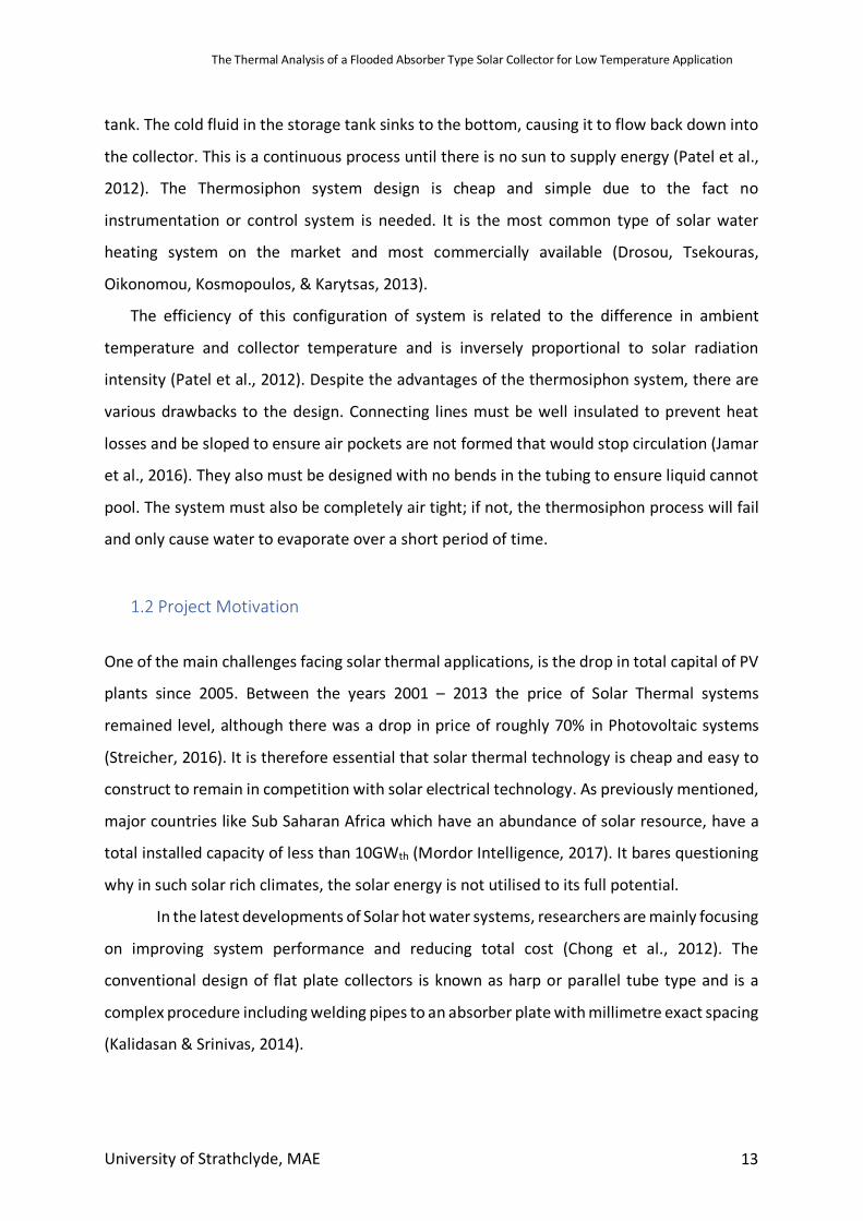
tank. The cold fluid in the storage tank sinks to the bottom, causing it to flow back down into
the collector. This is a continuous process until there is no sun to supply energy (Patel et al.,
2012). The Thermosiphon system design is cheap and simple due to the fact no
instrumentation or control system is needed. It is the most common type of solar water
heating system on the market and most commercially available (Drosou, Tsekouras,
Oikonomou, Kosmopoulos, & Karytsas, 2013).
The efficiency of this configuration of system is related to the difference in ambient
temperature and collector temperature and is inversely proportional to solar radiation
intensity (Patel et al., 2012). Despite the advantages of the thermosiphon system, there are
various drawbacks to the design. Connecting lines must be well insulated to prevent heat
losses and be sloped to ensure air pockets are not formed that would stop circulation (Jamar
et al., 2016). They also must be designed with no bends in the tubing to ensure liquid cannot
pool. The system must also be completely air tight; if not, the thermosiphon process will fail
and only cause water to evaporate over a short period of time.
1.2 Project Motivation
One of the main challenges facing solar thermal applications, is the drop in total capital of PV
plants since 2005. Between the years 2001 – 2013 the price of Solar Thermal systems
remained level, although there was a drop in price of roughly 70% in Photovoltaic systems
(Streicher, 2016). It is therefore essential that solar thermal technology is cheap and easy to
construct to remain in competition with solar electrical technology. As previously mentioned,
major countries like Sub Saharan Africa which have an abundance of solar resource, have a
total installed capacity of less than 10GWth (Mordor Intelligence, 2017). It bares questioning
why in such solar rich climates, the solar energy is not utilised to its full potential.
In the latest developments of Solar hot water systems, researchers are mainly focusing
on improving system performance and reducing total cost (Chong et al., 2012). The
conventional design of flat plate collectors is known as harp or parallel tube type and is a
complex procedure including welding pipes to an absorber plate with millimetre exact spacing
(Kalidasan & Srinivas, 2014).
The Thermal Analysis of a Flooded Absorber Type Solar Collector for Low Temperature Application
University of Strathclyde, MAE 14
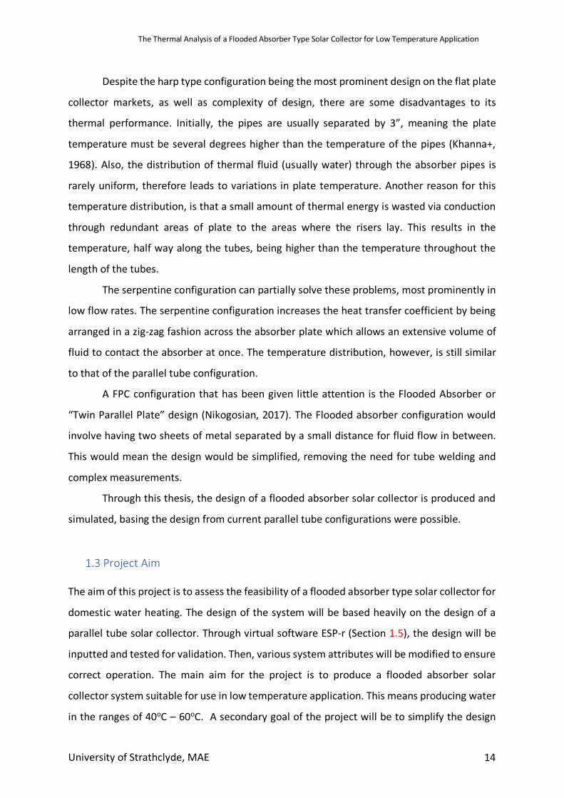
Despite the harp type configuration being the most prominent design on the flat plate
collector markets, as well as complexity of design, there are some disadvantages to its
thermal performance. Initially, the pipes are usually separated by 3”, meaning the plate
temperature must be several degrees higher than the temperature of the pipes (Khanna+,
1968). Also, the distribution of thermal fluid (usually water) through the absorber pipes is
rarely uniform, therefore leads to variations in plate temperature. Another reason for this
temperature distribution, is that a small amount of thermal energy is wasted via conduction
through redundant areas of plate to the areas where the risers lay. This results in the
temperature, half way along the tubes, being higher than the temperature throughout the
length of the tubes.
The serpentine configuration can partially solve these problems, most prominently in
low flow rates. The serpentine configuration increases the heat transfer coefficient by being
arranged in a zig-zag fashion across the absorber plate which allows an extensive volume of
fluid to contact the absorber at once. The temperature distribution, however, is still similar
to that of the parallel tube configuration.
A FPC configuration that has been given little attention is the Flooded Absorber or
“Twin Parallel Plate” design (Nikogosian, 2017). The Flooded absorber configuration would
involve having two sheets of metal separated by a small distance for fluid flow in between.
This would mean the design would be simplified, removing the need for tube welding and
complex measurements.
Through this thesis, the design of a flooded absorber solar collector is produced and
simulated, basing the design from current parallel tube configurations were possible.
1.3 Project Aim The aim of this project is to assess the feasibility of a flooded absorber type solar collector for
domestic water heating. The design of the system will be based heavily on the design of a
parallel tube solar collector. Through virtual software ESP-r (Section 1.5), the design will be
inputted and tested for validation. Then, various system attributes will be modified to ensure
correct operation. The main aim for the project is to produce a flooded absorber solar
collector system suitable for use in low temperature application. This means producing water
in the ranges of 40oC – 60oC. A secondary goal of the project will be to simplify the design
The Thermal Analysis of a Flooded Absorber Type Solar Collector for Low Temperature Application
University of Strathclyde, MAE 15
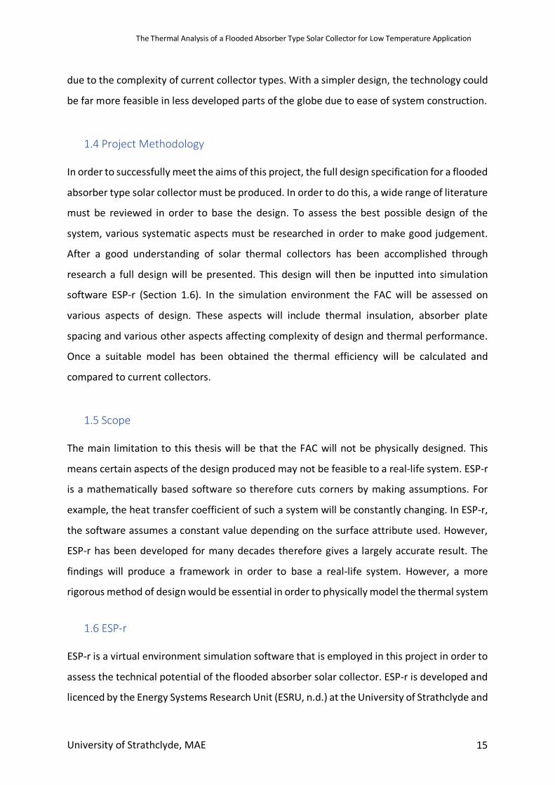
due to the complexity of current collector types. With a simpler design, the technology could
be far more feasible in less developed parts of the globe due to ease of system construction.
1.4 Project Methodology In order to successfully meet the aims of this project, the full design specification for a flooded
absorber type solar collector must be produced. In order to do this, a wide range of literature
must be reviewed in order to base the design. To assess the best possible design of the
system, various systematic aspects must be researched in order to make good judgement.
After a good understanding of solar thermal collectors has been accomplished through
research a full design will be presented. This design will then be inputted into simulation
software ESP-r (Section 1.6). In the simulation environment the FAC will be assessed on
various aspects of design. These aspects will include thermal insulation, absorber plate
spacing and various other aspects affecting complexity of design and thermal performance.
Once a suitable model has been obtained the thermal efficiency will be calculated and
compared to current collectors.
1.5 Scope The main limitation to this thesis will be that the FAC will not be physically designed. This
means certain aspects of the design produced may not be feasible to a real-life system. ESP-r
is a mathematically based software so therefore cuts corners by making assumptions. For
example, the heat transfer coefficient of such a system will be constantly changing. In ESP-r,
the software assumes a constant value depending on the surface attribute used. However,
ESP-r has been developed for many decades therefore gives a largely accurate result. The
findings will produce a framework in order to base a real-life system. However, a more
rigorous method of design would be essential in order to physically model the thermal system
1.6 ESP-r
ESP-r is a virtual environment simulation software that is employed in this project in order to
assess the technical potential of the flooded absorber solar collector. ESP-r is developed and
licenced by the Energy Systems Research Unit (ESRU, n.d.) at the University of Strathclyde and
The Thermal Analysis of a Flooded Absorber Type Solar Collector for Low Temperature Application
University of Strathclyde, MAE 16
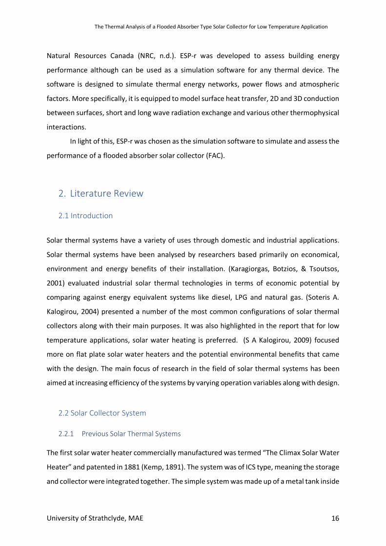
Natural Resources Canada (NRC, n.d.). ESP-r was developed to assess building energy
performance although can be used as a simulation software for any thermal device. The
software is designed to simulate thermal energy networks, power flows and atmospheric
factors. More specifically, it is equipped to model surface heat transfer, 2D and 3D conduction
between surfaces, short and long wave radiation exchange and various other thermophysical
interactions.
In light of this, ESP-r was chosen as the simulation software to simulate and assess the
performance of a flooded absorber solar collector (FAC).
2. Literature Review
2.1 Introduction
Solar thermal systems have a variety of uses through domestic and industrial applications.
Solar thermal systems have been analysed by researchers based primarily on economical,
environment and energy benefits of their installation. (Karagiorgas, Botzios, & Tsoutsos,
2001) evaluated industrial solar thermal technologies in terms of economic potential by
comparing against energy equivalent systems like diesel, LPG and natural gas. (Soteris A.
Kalogirou, 2004) presented a number of the most common configurations of solar thermal
collectors along with their main purposes. It was also highlighted in the report that for low
temperature applications, solar water heating is preferred. (S A Kalogirou, 2009) focused
more on flat plate solar water heaters and the potential environmental benefits that came
with the design. The main focus of research in the field of solar thermal systems has been
aimed at increasing efficiency of the systems by varying operation variables along with design.
2.2 Solar Collector System
2.2.1 Previous Solar Thermal Systems The first solar water heater commercially manufactured was termed “The Climax Solar Water
Heater” and patented in 1881 (Kemp, 1891). The system was of ICS type, meaning the storage
and collector were integrated together. The simple system was made up of a metal tank inside
The Thermal Analysis of a Flooded Absorber Type Solar Collector for Low Temperature Application
University of Strathclyde, MAE 17
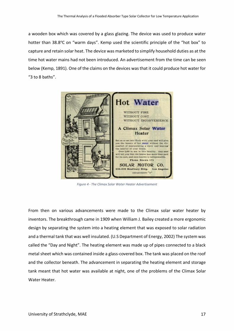
a wooden box which was covered by a glass glazing. The device was used to produce water
hotter than 38.8oC on “warm days”. Kemp used the scientific principle of the “hot box” to
capture and retain solar heat. The device was marketed to simplify household duties as at the
time hot water mains had not been introduced. An advertisement from the time can be seen
below (Kemp, 1891). One of the claims on the devices was that it could produce hot water for
“3 to 8 baths”.
Figure 4 - The Climax Solar Water Heater Advertisement
From then on various advancements were made to the Climax solar water heater by
inventors. The breakthrough came in 1909 when William J. Bailey created a more ergonomic
design by separating the system into a heating element that was exposed to solar radiation
and a thermal tank that was well insulated. (U.S Department of Energy, 2002) The system was
called the “Day and Night”. The heating element was made up of pipes connected to a black
metal sheet which was contained inside a glass-covered box. The tank was placed on the roof
and the collector beneath. The advancement in separating the heating element and storage
tank meant that hot water was available at night, one of the problems of the Climax Solar
Water Heater.
The Thermal Analysis of a Flooded Absorber Type Solar Collector for Low Temperature Application
University of Strathclyde, MAE 18
Just a few years previous, in 1905, a paper on the photoelectric effect had been published by
Albert Einstein. As a result, focus in solar technology was heavily motivated towards
photovoltaic devices, instead of thermal devices. Although, solar thermal devices were still
being sold on the market. From 1923 a large percentage of the housing in the Florida regions
used solar water heaters to heat domestic water as it was a cheaper alternative to coal or
wood. The system used was made up of a Flat Plate Collector and galvanized steel storage
tank, which operated on the thermosiphon principle. These systems however, were all
replaced by conventional hot water electric systems by 1951 (Scott, 1976)
New Installations of solar water heaters fell sharply from the early 1950’s due to three
principles. The first principle was the economic advantage that the solar thermal systems had
possessed was lost due to electric conventional systems being far cheaper to build. The
second principle was that the design problems were becoming more and more apparent and
the public were becoming aware. And the last principle was that a shift in building
development meant that large-scale building developers now had control over how houses
were built. The homeowner had little decision on what appliances would be implemented
into his/her dwelling. These building developers looked for the cheapest technologies on the
market and at the time electricity prices had been decreasing since the 1930’s. (Scott, 1976)
Throughout the next few decades, fossil fuels dominated the energy markets. As a result, the
spotlight drew from solar water heaters. However, basic solar water heaters were still used
around the world in countries such as Japan and Australia. Rice farmers used solar water
heaters in living quarters in order to bath. In Australia, through the late 1960’s and 1970’s,
solar devices were used to heat domestic water in thousands of homes. This spiked drastically
in due to the increase in oil price in 1972 and 1979. (California Solar Center, 2015)
Although in the 1980’s, the Solar Water Heater market in Australia began to stagnate again
with the introduction of pipelines that brought natural gas to places previously out of reach.
The need for solar heating devices became scarce. Solar water heaters were left largely
untouched by researchers in this decade. Although, some countries, such as Israel, did not
turn to conventional methods for water heating – worried by the fact the oil prices would
The Thermal Analysis of a Flooded Absorber Type Solar Collector for Low Temperature Application
University of Strathclyde, MAE 19
again spike. In 1983, 60% of the population used solar water heaters to heat water and
currently around 90% of Israeli households own solar water heaters (Scott, 1976)
In current times, with oil prices staying high and global warming being a pressing issue,
renewable energy such as solar water heating has come back into focus. New designs are
being produced for high efficiency, and various components are being studied in detail in
order to gain maximum performance.
2.3 The Flat Plate Collector The two main configurations on the market for stationary SWH are:
• Evacuated Tube Solar Collector (ETC)
• Flat Plate Solar Collector (FPC)
(Chong et al., 2012)
The ETC design consists of a header and heat pipe, manifold and evacuated tube. Although
efficiencies can be extremely high, they are the most expensive design of SWH (TheGreenAge,
2018). Flat plate solar collectors are the most common device used for domestic solar water
heating (Sö zen & Menlik, 2008). FPC’s are usually designed for working with temperatures
ranging between 40oC - 60oC which is generally the case with domestic hot water. FPCs are
advantageous over ETCs as they as they collect radiation coming from all angles (direct and
diffuse) which means they can be stationary at all times. Various investigations over the past
two decades have been aimed at reducing the FPCs thermal loss to the ambient environment
(Jeena & Nidhi, 2015).
The Thermal Analysis of a Flooded Absorber Type Solar Collector for Low Temperature Application
University of Strathclyde, MAE 20
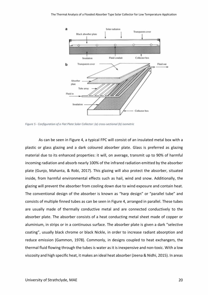
Figure 5 - Configuration of a Flat Plate Solar Collector: (a) cross-sectional (b) isometric
As can be seen in Figure 4, a typical FPC will consist of an insulated metal box with a
plastic or glass glazing and a dark coloured absorber plate. Glass is preferred as glazing
material due to its enhanced properties: it will, on average, transmit up to 90% of harmful
incoming radiation and absorb nearly 100% of the infrared radiation emitted by the absorber
plate (Gunjo, Mahanta, & Robi, 2017). This glazing will also protect the absorber, situated
inside, from harmful environmental effects such as hail, wind and snow. Additionally, the
glazing will prevent the absorber from cooling down due to wind exposure and contain heat.
The conventional design of the absorber is known as “harp design” or “parallel tube” and
consists of multiple finned tubes as can be seen in Figure 4, arranged in parallel. These tubes
are usually made of thermally conductive metal and are connected conductively to the
absorber plate. The absorber consists of a heat conducting metal sheet made of copper or
aluminium, in strips or in a continuous surface. The absorber plate is given a dark “selective
coating”, usually black chrome or black Nickle, in order to increase radiant absorption and
reduce emission (Gammon, 1978). Commonly, in designs coupled to heat exchangers, the
thermal fluid flowing through the tubes is water as it is inexpensive and non-toxic. With a low
viscosity and high specific heat, it makes an ideal heat absorber (Jeena & Nidhi, 2015). In areas
The Thermal Analysis of a Flooded Absorber Type Solar Collector for Low Temperature Application
University of Strathclyde, MAE 21
where there is an average availability of solar radiation, flat plate collectors are sized
approximately one half to one square foot per gallon of one days hot water (Moss et al., 2017)
The main idea behind a flat plate solar collector is that solar energy is converted into
heat energy when sunlight passes through the glazing and strikes the absorber plate. This
heat is then convectively transferred to the heat transfer medium inside the finned tubes. In
an active system, the flowrate circulates at a constant rate. In the case of a passive system,
as the flow medium heats up, the density drops and the “hotter part” flows up and out of the
header tubes. These tubes are often of a larger diameter to encourage this process. (S.
Kalogirou, 2014).
2.3.1 Absorber Modifications One of the most important features of the solar water heater is the absorber. The absorber
is responsible for taking the solar radiation and passing in into the heating medium. Absorber
plates have undergone many modifications with the aid of better techniques in
manufacturing and material science (Pandey & Chaurasiya, 2016).
Within the design of the solar absorption plate, the primary construction materials tend to be
either Steel, Copper or Aluminium. Steel is a lesser choice although it is a truly sustainable
material. Once steel is made, it can be used as steel forever. Copper is the most common
material choice due to its high thermal performance over the other absorber materials.
Copper is also very resistant to corrosion, adding to its lifetime. Aluminium has a slightly lower
thermal conductivity than Copper however its low weight makes up for this. When solar
absorber systems increase in size, a light weight construction material is desirable if the
collector is going to be placed on top of roofing. Since these materials are not strongly
absorbing, especially Aluminium, a coating must be provided which absorbs solar radiation
(Lenel, 1984).
Plastics can also be used for the absorber material. Materials such as Polypropylene and
acrylic can be pigmented with black and used as highly conductive absorber plates. Plastics
can also be produced to be transparent and formed in such a way that liquid can pass in
The Thermal Analysis of a Flooded Absorber Type Solar Collector for Low Temperature Application
University of Strathclyde, MAE 22
between. The coloured liquid contained inside the plastic is picked so that high thermal
conductance can be achieved (Lenel, 1984).
The heat transferred to the fluid depends not only on the thermal conductivity of the material
but also on the distance between fluid passageways. (Lenel, 1984) looked at the different
materials and configurations of fluid passageways to lower cost of solar thermal heaters. In
the study he found that different configurations of absorber allow for lower thermally
conductive materials to be used in the design.
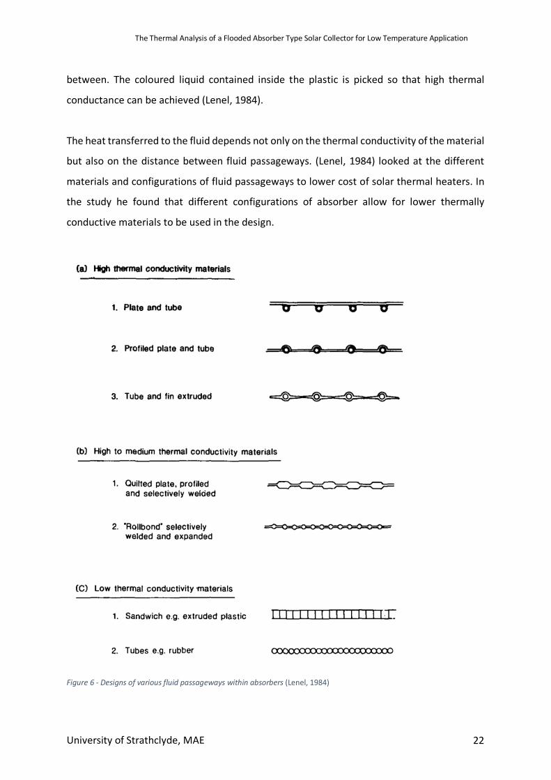
Figure 6 - Designs of various fluid passageways within absorbers (Lenel, 1984)
The Thermal Analysis of a Flooded Absorber Type Solar Collector for Low Temperature Application
University of Strathclyde, MAE 23
Shown in Figure 6 are several different typical absorber configurations. Plate & tube and Tube
& Fin designs are commonly used with high thermally conductive materials like Copper and
Aluminium. In these designs, heat is transferred through the plate or fin to the fluid carrying
tubes. The quilted or roll bond design consists of selectively welded plates that can be spaced
accordingly, depending on the thermal conductivity of absorber material. Materials with the
lowest thermal conductivity tend to be arranged in sandwich form or close tubing (Figure 6c).
When the thermal conductivity of the material used is very low, the heat transfer path must
be very short. It is possible to use plastics in configurations such as plate & tube, however
most of the absorber surface must be in contact with the fluid and the contact walls must be
extremely thin (Blaga, 1978)
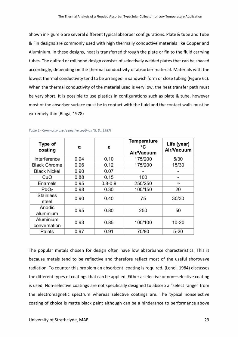
Table 1 - Commonly used selective coatings (G. D., 1987)
The popular metals chosen for design often have low absorbance characteristics. This is
because metals tend to be reflective and therefore reflect most of the useful shortwave
radiation. To counter this problem an absorbent coating is required. (Lenel, 1984) discusses
the different types of coatings that can be applied. Either a selective or non–selective coating
is used. Non-selective coatings are not specifically designed to absorb a “select range” from
the electromagnetic spectrum whereas selective coatings are. The typical nonselective
coating of choice is matte black paint although can be a hinderance to performance above
The Thermal Analysis of a Flooded Absorber Type Solar Collector for Low Temperature Application
University of Strathclyde, MAE 24
40oC and has relatively high infrared emittance. Selective coatings consist of two layers. An
upper layer to absorb shortwave radiation, while transmitting long wave radiation and a
lower layer to absorb long wave radiation. Selective surfaces are particularly useful in colder
climates where the exterior environment is colder than that of the surface of the solar
collector (Lampert, 1979). Table 1 summarise the details of the most commonly used
selective surfaces.
(Madhukeshwara & Prakash, 2012) also presented a study concerning the selective surface
coatings added to the absorber. It was reported that a good selective surface consists of a
material that enables only a small fraction of solar radiation to be lost due to reflection and
radiation. The selectivity of the surface is defined as the ratio of the solar radiation absorbed
to the thermal radiation emitted. Characteristics of a good selective surface combine a low
emittance in the relative temperature range with a high absorbance for radiation. If the
selectivity of a surface is low, it may be enhanced by the addition of filters. In the study, it was
found that black chrome had the best selectivity and so achieved the highest water
temperatures. In their findings, the absorptivity of black chrome was found to be 0.93 and
the emissivity was 0.11 giving a selectivity result of 9.3.
2.3.2 Absorber Efficiencies (Karim, Nakoa, Mahmood, & Akhanda, 2012) reported on the effects different absorber
colours may have on the performance of flat plate solar water heaters. On an average basis,
blue and black absorbers performed better than colourless and red-brown absorbers. The
highest monthly efficiencies for the blue and black absorbers were 53% and 57% respectively,
fixed at a 23.5o angle to the horizontal. The maximum temperature achieved for each
absorber colour was: 41oC for colourless, 43oC for red-brown, 50oC for blue and 54oC with
black.
(Amrutkar, Ghodke, & Patil, 2012) conducted a study under laboratory conditions evaluating
the performance of an FPC with different absorber geometries. Collector area was varied
from 1.9m2 – 2.5m2 and systems from Sunbeam Solar, Tata BP solar system, Jain Solar, Avin
The Thermal Analysis of a Flooded Absorber Type Solar Collector for Low Temperature Application
University of Strathclyde, MAE 25
Solar, along with many others were used in the study. The maximum storage temperature
ranged from 50oC to 70oC and efficiencies of collector from 55% to 71%. The aim of their study
was to prove that there was a significant drop in capital with the increase in efficiency of
collector.
2.3.3 Alternate Designs
Attempts have been made over the years to change the design of the collector from most
common configurations like the Evacuated Tube Solar Collector (ETC) and Flat Plate Solar
Collector (FPC) (Chong et al., 2012). It has been reported that collector arrangement has the
biggest influence on thermal performance (Van Niekerk, du Toit, & Scheffler, 1996)
(Rommel et al., 1997) experimented with various different absorber geometries, contrary to
the norm used with metal absorbers. This was possible due to the polymer material, which
was used, being easily shaped. There main aim was to create a corrosion free collector system
by creating a selectively coated plastic absorber. In result of their research, they found that
an absorber geometry of heating fluid contacting rectangular channels had performance
characteristics of that of fin and tube absorbers.
2.3.4 Enhancement Devices (Hobbi & Siddiqui, 2009) reported on an experimental study to investigate what impact heat
enhancement devices had on flat plate solar collectors. Various passive heat enhancement
devices were studied including twisted strip, coil spring wire and conical ridges although none
of the devices showed appreciable difference in heat flux to the collector fluid. It was also
indicated that the main heat transfer mechanism in solar collectors were of mixed convection
type with free convection as the dominant heat transfer mode.
(Z. Chen, Furbo, Perers, Fan, & Andersen, 2012) carried out a study of the potential efficiency
increase of using Ethylene Tetra Fluro Ethylene (ETFE) foil in a flat plate solar collector. They
compared the result of the ETFE foil collector with that of copper collector. Different flow
rates of heating medium were trialled and efficiencies of each collector estimated. It was
The Thermal Analysis of a Flooded Absorber Type Solar Collector for Low Temperature Application
University of Strathclyde, MAE 26
established that the collector with the ETFE foil had a higher yearly thermal performance
when average temperatures were above 30oC. It was also found that when the volumetric
flowrate of the fluid through the collector was increased, the efficiency of the system also
increased while the heat loss coefficient decreased.
Nanoparticles and Nanofluids have been in the spotlight for research and development of
Solar thermal systems in recent years. (Meibodi, Kianifar, Niazmand, Mahian, & Wongwises,
2015) evaluated the role of nanofluids on heat transfer enhancement within flat plate solar
collectors. Tests were taken using SiO2/ethylene glycol water nanofluid with volume fractions
up to 1%. It was found that the effects of particle loading on thermal efficiency was more
defined at lower values of heat loss coefficient. The potential of SiO2 nanoparticles is
highlighted in this study for thermal enhancement despite the lower thermal conductivity of
other similar nanoparticles.
(Jouybari, Saedodin, Zamzamian, Nimvari, & Wongwises, 2017) studied the effects of
nanofluid particle size on thermal efficiency of flat plate collectors. It was found that the
efficiency of system decreases with diminishing particle size. (Kumar Verma, Kumar Tiwari, &
Singh Chauhan, 2017) tested different nanoparticles mixed into the water heating medium.
Of all nanoparticles tested, the exergy efficiency of system was increased by 29.32% by a
graphene/water mixture showing graphene’s potential in thermal systems.
2.3.5 Glazing The glazing of the solar collector primarily reduces convective losses to the environment from
the upward facing side of the absorber while still allowing solar radiation to pass through. The
glazing’s secondary function is absorber protection.
The most widely used material for the glazing of the collector is tempered glass. Tempered
glass can achieve a 90% transmittance due to the low iron content. Iron is often found in glass
and can be detrimental to transmittance even at very low concentrations. When performing
energy calculations for glass standards, roughly 2% of the radiative energy is absorbed by the
glass therefore it is often disregarded. However, tempered glass can be fragile and is very
The Thermal Analysis of a Flooded Absorber Type Solar Collector for Low Temperature Application
University of Strathclyde, MAE 27
heavy compared to its polymer competitors. The glass is prone to breaking when bonded to
the frame of the collector (Köhl, 2012).
Using multiple layers of glazing is a topic that has been discussed thoroughly in research
(Kalidasan & Srinivas, 2014; Köhl, 2012; Singh, Sarviya, & Bhagoria, 2010). (Kalidasan &
Srinivas, 2014) also looked into the benefits of more than one layer of collector glazing. It
was found that on colder days, when the absorber temperature was lower, a single layer of
glazing was superior to a double layer as the single layer transmitted larger amounts of useful
energy. However, when the general exterior temperature was higher, meaning the absorber
temperature was higher – more than one layer was advantageous due to the increased
trapping potential of extra layers of glazing. A compromise must be taken depending on the
environment the solar collector is being placed in. (Singh et al., 2010)
reported that there was a 10% - 15% decrease in heat loss coefficient with a double layer
compared to that of a single layer of glazing.
(Kalidasan & Srinivas, 2014) studied the effects of different numbers of covers (glazing) and
refractive index to improve optical and thermal efficiencies of collectors. It found that a
reliable cover should have low transmissivity for long wave radiation and high transmissivity
for shortwave radiation. These two attributes together are commonly known as the
“greenhouse effect”. Having low emittance in the long wave spectrum means that radiation
will be trapped inside the collector, giving the absorber more opportunity to heat up and
therefore increase efficiency. The shortwave radiation contains most of the useful energy
therefore it is important that this energy can easily make its way to the absorber plate, hence
high transmittivity for short wave desirable.
(Bakari, Minja, & Njau, 2014) looked into how glazing thickness effected the performance of
a flat plate collector. A glass glazing was used to ensure reflection and absorption was as low
as possible and transmission was as high as possible. Glazing of 3,4,5 and 6mm were used
(low iron content glass) and it was found 4mm thickness attained the best increase in
performance of 7.6%. The downside to a thinner sheet of glass, however, is that risk of
breakage during construction is increased.
The Thermal Analysis of a Flooded Absorber Type Solar Collector for Low Temperature Application
University of Strathclyde, MAE 28
Polymers can also be used for glazing material. (S A Kalogirou, 2009) looked at the potential
of such polymer materials. It was found that the biggest downfall of using polymers, such as
plastic, for the glazing layer is that they have high transmittance in the longwave spectrum.
This means energy can escape more readily from the absorber than with tempered glass. The
longwave transmittance of plastics can reach up to 0.4 which, considering tempered glass is
as low as 0.02, proves to be a big problem with deployment. In the shortwave spectrum,
plastics compare better with glass, however still fall short. The transmittance absorbance
ratio for polymers averages around 0.7 while for glass its 0.8 (higher value desirable for
shortwave transmittance). Despite this, polymers such as Polycarbonate are on the market
for other reasons such as their low weight and cost and the possibility of being made into
almost any shape or structure.
A study was undertaken by (Köhl, 2012) to look into the performance characteristics of 58
different polymer materials for use as solar glazing. Out of all the polymers tested, only two
were selected to rival tempered glass. One was PMMA (acrylic) and the other was
Polycarbonate (PC). However, the materials were only tested for short periods of time. It was
found that after a reasonable number of working hours, degrading due to UV exposure
started to affect the PC glazing so much that it changed in dimensions. PMMA also
experienced some of these changes although to a much lesser extent.
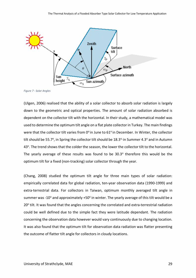
2.3.6 Optimum Tilt The level of solar radiation that is absorbed by a solar collector depends on many variables
including azimuth angle, location altitude, declination angle, etc (Figure 8). Out of all the
variables, most are controlled by nature although the azimuth angle (horizontal measured
clockwise) and tilt angle (inclination) are set manually.
It is well established that the optimum azimuth angle for FPCs is zero when south facing,
although tilt angle has not been as well defined. Tracking can be done with solar collectors
although it is an expensive technology and cannot be installed with many solar devices.
The Thermal Analysis of a Flooded Absorber Type Solar Collector for Low Temperature Application
University of Strathclyde, MAE 29
Figure 7 - Solar Angles
(Ulgen, 2006) realised that the ability of a solar collector to absorb solar radiation is largely
down to the geometric and optical properties. The amount of solar radiation absorbed is
dependent on the collector tilt with the horizontal. In their study, a mathematical model was
used to determine the optimum tilt angle on a flat plate collector in Turkey. The main findings
were that the collector tilt varies from 0o in June to 61o in December. In Winter, the collector
tilt should be 55.7o, in Spring the collector tilt should be 18.3o, in Summer 4.3o and in Autumn
43o. The trend shows that the colder the season, the lower the collector tilt to the horizontal.
The yearly average of these results was found to be 30.3o therefore this would be the
optimum tilt for a fixed (non-tracking) solar collector through the year.
(Chang, 2008) studied the optimum tilt angle for three main types of solar radiation:
empirically correlated data for global radiation, ten-year observation data (1990-1999) and
extra-terrestrial data. For collectors in Taiwan, optimum monthly averaged tilt angle in
summer was -10o and approximately +50o in winter. The yearly average of this tilt would be a
20o tilt. It was found that the angles concerning the correlated and extra-terrestrial radiation
could be well defined due to the simple fact they were latitude dependant. The radiation
concerning the observation data however would vary continuously due to changing location.
It was also found that the optimum tilt for observation data radiation was flatter presenting
the outcome of flatter tilt angle for collectors in cloudy locations.
The Thermal Analysis of a Flooded Absorber Type Solar Collector for Low Temperature Application
University of Strathclyde, MAE 30
(Al-Rawahi, Zurigat, & Al-Azri, 2011) presented a comparison of predicted hourly terrestrial
solar radiation on a horizontal surface. The predicted results were based on isotropic
reflection on diffuse radiation and showed that in Muscat, the optimum tilt angle for January
is 40o for an azimuth of 0o (South facing). In Winter, it is found that a horizontal angle tilt is
best suited to maximum solar absorption.
(Eke, 2011) experimented with a flat plate collector of area 0.5m2. The FPC was hinged on a
support for quick tilt angle adjustment from 0o-90o. Measurements were taken for clear sky
hours from 12:00 to 14:30 in Zaria, Nigeria. A solar radiometer took averaged measurements
over each degree of tilt. The study showed that the optimum tilt angles were 26.5o, 24.5o,
10.0o, 19.5o, 26.0o, 30.0o, 24.0o, 21.0o, 11.5o, 19.5o, 27.0o, 30.0o from January – December,
respectively. The averaged angle of inclination for Zaria was found to be 22.5o and this was
found to have a small increase of 4.23% in solar intensity of that of a horizontally orientated
FPC. The observation was made that the calculated and measured solar energy intensities
incident on the collector surface increased in intensity from an angle of 25o – 30o and
thereafter fell in intensity.
(Nnamchi, 2012) focused on optimum tilt angles for areas of low latitude in Nigeria. They
developed expressions for monthly optimum tilt based on latitude in monthly increments for
a year. The main finding of the study was that tilt angle for maximum insolation was different
for various locations based on the area latitude. Polynomial expressions linking insolation
with latitude were developed. The results obtained compared favourably with the literature.
(Keshavarz, Talebizadeh, Adalati, Mehrabian, & Abdolzadeh, 2012) determined values of
optimum tilt for every day of a year in 30 different Iranian cities in order to create a map of
maximum insolation locations. These values were averaged weekly, monthly and yearly and
then an atlas of optimum slope angle and maximum energy gain was developed. The
Geographic Information System (GIS) was used to outline the maps. The radiation predicted
in all locations were compared with that of real data from 1983 – 2005 that was recorded by
IMO (Iranian Meteorological Organization). The optimum tilt angle through January was
The Thermal Analysis of a Flooded Absorber Type Solar Collector for Low Temperature Application
University of Strathclyde, MAE 31
found to vary from 46o – 56o. The angle changed to negative tilt angles of -5.3o – 2.3o through
Summer month June.
2.3.7 Heat Loss Reduction
One of the main factors to solar collector performance is the amount of heat the system can
contain from the environment. The insulation layer must completely encapsulate the
collector, just leaving the glazing area uninsulated for solar radiation. Although no insulation
can completely remove thermal losses, a number of attempts have been made to find the
best suitable material for the task.
Vacuum insulation has been looked into by various different researchers. (El-Sherbiny,
Hollands, & Raithby, 1978) conducted one of the first experiments for free convective heat
transfer across inclined air layers, heated from below and bounded by one flat plate and one
corrugated plate. The results showed that the solar collector’s efficiency was not majorly
effected by an air gap of 20mm between the casing and rear absorber plate. (Monterrey,
2008) realised a potential problem with vacuum sealing was the fact that due to the different
expansion coefficients between metal and glass, the vacuum seal would usually fail if rapid
temperature changes occurred. In order to sustain the vacuum seal, a pump, powered by
solar panels was inserted in line with the FPC. This protection method was only needed with
high temperature applications.
(Al-Beaini, Benhabib, Engelage, & Langton, 2007) described the most commonly used
materials for insulation in solar collectors as mineral wool, glass wool, fibreglass and
polyurethane. However, the use of fiberglass (Glass wool) can be detrimental if high
temperatures occur. If temperatures are higher than the particulates melting point, they can
evaporate into the absorber area and condensate on the glazing, reducing transmittivity.
However, as glass wool was extremely cheap, it is highly suitable for use below temperatures
with low temperature application.
(Beikircher, Berger, Osgyan, Reuß, & Streib, 2014) looked into alternatives to mineral wool
for insulation. Flat plate collectors are usually insulated by a 40-60mm layer of mineral wool.
The reason for the research was the fact wool can absorb humidity through the collector’s
The Thermal Analysis of a Flooded Absorber Type Solar Collector for Low Temperature Application
University of Strathclyde, MAE 32
lifetime which greatly decreases the insulation properties. Mineral wool has a thermal
conductivity between 0.035 and 0.06 W/mK but it was show that if the wool was removed,
the air chamber remaining (assuming adequately confined), has acceptable insulation
properties. The study showed that absorber rear side losses with mineral wool are around 1
W/m2K when empty while a well confined chambers losses are in the region of 1.5-2W/m2K.
It was also found that Aluminium foil, positioned parallel between absorber and rear casing
showed similar properties to mineral wool, but had no affinity to absorb humidity.
Thicknesses of foil between 30-50mm showed comparable and even slightly better
performance than mineral wool.
(Beikircher, Möckl, Osgyan, & Streib, 2015), the year later, looked at advanced methods of
insulation. TIM or Transparent Insulating Material can be used to actually insulate the front
cover of the collector. TIM is made up of a honeycomb network and has transmittance rating
of up to 98% for direct radiation. This high transmittance means that it is suitable to insulate
the glazing. On the other hand, for diffuse radiation, the transmittance is dependent on the
thickness of the TIM layer. A compromise must be made to be thick enough to scatter infrared
radiation while also thin enough to transmit diffuse radiation. Using a 40mm thick honeycomb
layer, a heat loss coefficient of 2W/m2 was found, which is double that of fibreglass (lower
value desirable for low heat conduction). However, it was found with TIM that degradation
occurs at high temperatures which causes softening.
(Hirasawa, Tsubota, Kawanami, & Shirai, 2013) looked at reducing radial heat loss from the
collector by placing a porous medium on top of the absorption system. The shading effect on
the copper tubing absorption system had to be minimised in order to maximise solar radiation
gains. In their experiment, they used a series of offset wire screens made of fine nylon fishing
lines to create a string net layer. This layer was situated between the absorber and glass plate.
The result of their experiment found that the net reduction of heat loss by natural convection
was 7% when the porous medium was placed above the absorber. However, total losses from
the shading effect caused were not discussed.
The Thermal Analysis of a Flooded Absorber Type Solar Collector for Low Temperature Application
University of Strathclyde, MAE 33
2.4 Application of Flat Plate Collectors
2.4.1 Desalination Water Desalination in simple terms means to remove salt from water. Over the past two
decades, low temperature desalination has not progressed passed the demonstration stage.
International standards report that a minimum of 5l/day per person and 10l/day per person
is need in average and hot climates for consumption respectively (Ayoub & Alward, 1996).
(Schwarzer, Vieira, Müller, Lehmann, & Coutinho, 2003) produced a simple desalination
system consisting of simply a flat plate collector and a desalination tower with heat recovery.
The system was aimed at purifying either sea or salty ground water for human consumption.
The flat plate collector implemented could either be used in direct or indirect heating mode.
In the indirect configuration, an additional thermal oil is needed for heat transport. The
desalination tower has six stages and incorporates a water circulation system in each stage
to ensure salt doesn’t build up. The water was rendered drinkable when the laboratory tests
showed that the Coliform group bacteria was eliminated.
(Sengar, 2004) studied the performance of an FPC when coupled to a small scale distillation
system. Hot water production was also investigated. 100 litres of water was heated using a
FPC system of area 2m2 and tilt angle of 45o facing south. Tests were conducted seasonally,
and maximum water temperature was found at 58.3oC and 48.7oC in summer and winter
respectively. It was found that the collector system obtained efficiencies ranging from 27.48%
to 35.7%.
(S. Kalogirou, 2005) presented various techniques of salt water desalination using renewable
energy technologies. The need for water desalination technologies were highlighted in this
paper due to the energy crisis. The current systems in place like MED, MSF, vapor
compression and many others were analysed and discussed with focus on energy usage. A
review of current renewable energy desalination technologies included solar ponds,
photovoltaic and wind energy systems. It was found that one of the most promising
renewable energy technologies for water desalination, was solar energy.
The Thermal Analysis of a Flooded Absorber Type Solar Collector for Low Temperature Application
University of Strathclyde, MAE 34
(Joseph, Saravanan, & Renganarayanan, 2005) used a solar collector of 5m2 in order to obtain
a 10:1 yield of potable water (drinkable). A maximum distillate of 8.5 l/day was achieved with
a maximum efficiency of 26%. The efficiency ranged from 15%-26% over the insolation fluxes
of 400 – 900 W/m2. Using this technology, not only was the purity well above limits but the
capital of such water was low compared to that of conventional cleaning systems.
(Wessley & Mathews, 2014) conducted an experiment to test the performance of FPCs for
small scale desalination applications in India. The study presented that a maximum water
temperature of 64oC was found on a solar rich day of 932.2 W/m2. The efficiency of the 2m2
collector was recorded at 43.4%. The study also comments on the fact the maximum water
temperature obtained is directly related to the availability of solar radiation. Losses via
convection were also found around the collector due to wind velocity – highlighting the
importance of insulation.
2.4.2 Domestic Hot Water
Large amounts of energy are expended in obtaining hot water for domestic use. Shortages of
supplies, harmful carbon emissions and expensive utility bills are all consequences of
producing hot water in the home via conventional methods. In a typical UK household, more
than half the money spent on fuel bills goes towards providing hot water and heating (Energy
Saving Trust, 2018). In terms of developing nations, hot water for bathing and cooking is often
the most expensive and time-consuming process in the household energy budget. If the
upfront prices of solar water systems was competitive with current methods, they could
produce a sustainable solution for poor households. (Al-Beaini et al., 2007)
(Al-Beaini et al., 2007) discussed in detail the potential of solar water heating to replace
current methods of water heating in less developed nations. In communities in poorer parts
of the world, obtaining enough hot water to live on is a problem. Households that do not have
electricity rely on either biomass or wood to burn to produce hot water. In many areas,
demand for wood has been the major cause of deforestation.
The Thermal Analysis of a Flooded Absorber Type Solar Collector for Low Temperature Application
University of Strathclyde, MAE 35
Household water usage varies enormously depending on how many occupants are living in a
house, alongside their personal needs. According to the DEFRA, the average person in the UK
uses around 142 litres of water each day (DEFRA, 2013). The average household uses 349
litres of water each day. The hot water used contributes to £228 to the average combined
energy bill annually and emits 875kg of CO2 per year when produced by natural gas boiler.
2.5 Calculation
2.5.1 Efficiency Calculation (Huang & Du, 1991) developed a mathematical method to calculate the thermal performance
of a solar collector. The method developed takes real data from experimental and applies this
in the method. They found that the hot water load pattern was a complicated factor that
effected the system performance during load phase. It was found that if the hot water load
pattern was standardized, this problem could be solved. For accurate results, the variation of
daily loads should be small. For the test method the assumptions made were:
• The temperature of the whole system can be represented by a system mean
temperature
• The system mean temperature equals the mean water temperature of the tank
• Neglect the heat capacity effect of the construction material of the system
The instantaneous system performance must be integrated over the total energy collecting
period per day (e.g. from sunrise to sun set). Therefore, an energy balance over the whole
system and integrating over a full day (ignoring heat capacity effects) gives:
𝑄"#$ = 𝑄9 − 𝑄:;<<
Eqn. 1
Qnet is the total energy absorbed daily and can be expressed as:
𝑄"#$ = 𝑀𝐶E`𝑇I − 𝑇La
Eqn. 2
The Thermal Analysis of a Flooded Absorber Type Solar Collector for Low Temperature Application
University of Strathclyde, MAE 36
Qc is the total daily radiation absorbed by the collector which is assumed to be proportional
to the daily irradiation total, incident on the collector surface (Ht) and collector area (Ac)
where ae is a proportionality constant:
𝑄9 = 𝛼#𝐴9𝐻$
Eqn. 3
The total daily irradiation incident upon the collector surface can be expressed via the
integral:
𝐻$ = b 𝐼$𝑑𝑡$c
$d
Eqn. 4
Where the initial and final time bounds are represented by ti and tf. The total daily heat loss
is assumed to be proportional to the difference of the average tank temperature and average
ambient dry bulb temperature:
𝑄:;<< = 𝑈$(𝑇Y − 𝑇ZY)
Eqn. 5
Where Ut is the total heat loss coefficient, which acts as another proportionality constant. To
further simplify the equation, it is further assumed that the daily mean system temperature
T’ can be taken as the average between the initial and final temperatures of the water
achieved;
𝑇Y =`𝑇L + 𝑇Ia
2
Eqn. 6
The energy balance (Eqn. 1) can be written in terms of equation 2, equation 3 and equation
5. The result, per unit collector area, is written as:
𝑞"#$ =𝑄"#$𝐴9
= 𝛼#𝐻$ − 𝑈<(𝑇Y − 𝑇ZY)
Eqn. 7
The Thermal Analysis of a Flooded Absorber Type Solar Collector for Low Temperature Application
University of Strathclyde, MAE 37
US in the developed energy balance is simply the overall heat loss coefficient per unit area.
Then to calculate the daily system efficiency relation, the energy balance is divided by the
incident total solar radiation upon the collector surface (Ht) giving:
𝜂< =𝑞"#$𝐻$
= 𝛼# −𝑈<(𝑇Y − 𝑇ZY)
𝐻$
Eqn. 8
2.6 Conclusion It is apparent that there has been in-depth research into the design and upgrade of solar
thermal collectors. Experiments and computer aided models have been developed in order
to precisely obtain performance data to further improve the design of solar collectors. In
general, flat plate solar collectors have received the most attention.
Research has shown the effects of variables such as inclination angle, water inlet
temperature, total solar flux, ambient conditions and design. Within the broad scope of
research, there has been little attention towards the flooded absorber type solar collector.
Throughout the rest of this report, the design considerations, design and thermal analysis of
design shall be conducted in order to assess the performance of such an absorber design.
3. Design Considerations
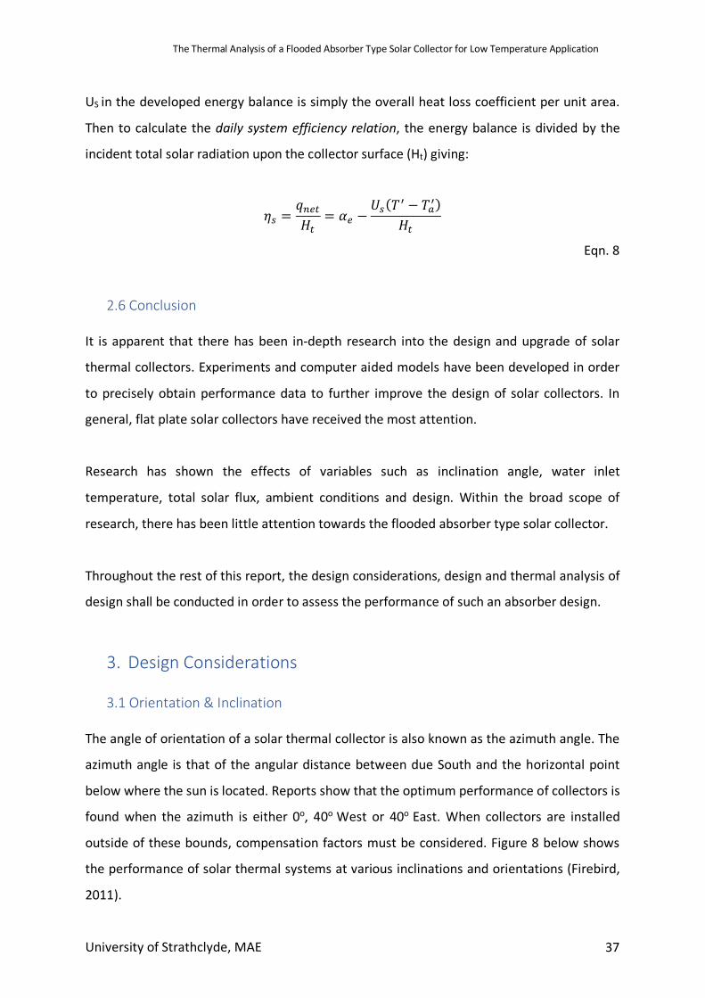
3.1 Orientation & Inclination The angle of orientation of a solar thermal collector is also known as the azimuth angle. The
azimuth angle is that of the angular distance between due South and the horizontal point
below where the sun is located. Reports show that the optimum performance of collectors is
found when the azimuth is either 0o, 40o West or 40o East. When collectors are installed
outside of these bounds, compensation factors must be considered. Figure 8 below shows
the performance of solar thermal systems at various inclinations and orientations (Firebird,
2011).
The Thermal Analysis of a Flooded Absorber Type Solar Collector for Low Temperature Application
University of Strathclyde, MAE 38
Figure 8 - Inclination and Orientation Angles (Firebird,2011)
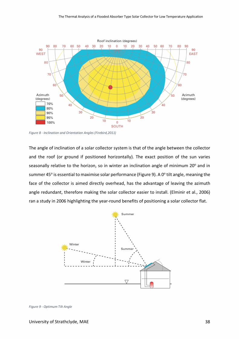
The angle of inclination of a solar collector system is that of the angle between the collector
and the roof (or ground if positioned horizontally). The exact position of the sun varies
seasonally relative to the horizon, so in winter an inclination angle of minimum 20o and in
summer 45o is essential to maximise solar performance (Figure 9). A 0o tilt angle, meaning the
face of the collector is aimed directly overhead, has the advantage of leaving the azimuth
angle redundant, therefore making the solar collector easier to install. (Elminir et al., 2006)
ran a study in 2006 highlighting the year-round benefits of positioning a solar collector flat.
Figure 9 - Optimum Tilt Angle
The Thermal Analysis of a Flooded Absorber Type Solar Collector for Low Temperature Application
University of Strathclyde, MAE 39
Some solar panels used for heating concentrate radiation and some do not. For low to
medium temperature requirements, panels do not and for high heating requirements solar
panels do. Hot water heating comes under low temperature technology and technologies
heating up water tend not to be solar concentrating.
3.2 Collector Materials
Materials selected for design need to meet major design objectives: high temperature
stability, low cost, weatherability and durability. An important design aspect of a surface used
for exchanging heat is selecting an appropriate material in order to transfer heat efficiently
and quickly.
Copper is generally chosen for collector surface as it is an excellent conductor of heat as it has
a high thermal conductivity (Amrutkar et al., 2012) (Hirasawa et al., 2013). Copper also has
high corrosion resistance, high maximum allowable stress and pressure and high specific heat
(Table 3). It also has cost benefits due to ease off joining and ease of fabrication.
For basic surface enhancement of the absorber, a layer of black “paint” is applied to the top
surface. This “paint” can be made of a range of materials although Titanium Dioxide is a
popular choice (X. Chen, Liu, Yu, & Mao, 2011). Although Titanium is an expensive metal, it is
applied in such a small amount this doesn’t affect collector price significantly (X. Chen et al.,
2011)
Insulation of the collector can be done in a number of ways. Vacuum sealing the collector has
been reported to work well in reducing thermal losses (Joseph et al., 2005). The problem with
vacuum sealing in the lifetime of a collector, is that air can make its way in through very small
ruptures in the sealing and completely remove insulation properties. Glass wool is a cheap
and abundant insulation material. With thermal conductivities of 0.04W/mK, it has excellent
heat containing properties (Sengar, 2004)
The Thermal Analysis of a Flooded Absorber Type Solar Collector for Low Temperature Application
University of Strathclyde, MAE 40
3.3 Thermal Expansion
The major areas where thermal stresses affect an FPC is where the absorber joins the frame.
The stresses are increased further if the absorber and headers are only connected at each
end of the solar collector. This is due to the fact large temperature differences between the
frame and absorber can cause differential thermal expansion of the absorber and the frame.
(Russell, 2015). This problem can be solved by using expansion joints or slots in the enclosure
frame to allow relative motion between the frame and the header connectors. Although, this
option will add to an increased complexity with design. A simpler answer to this problem is
presented by ensuring the frame and absorber/headers are made from materials with the
same CLTE numbers.
If materials that are connected within the solar collector have significantly different
coefficients of linear thermal expansion (CLTE), large thermal stresses occur through the
changing of temperature. Therefore, the manifold, connecting absorber and connector pieces
in a flat plate collector all must be of the same CLTE, or very similar. The back cover, top cover
and Frame all have the same CTLE as the manifold, absorber and connector (Firebird, 2011).
However, using a flooded absorber, mean that the two plates can be left relatively freely
inside the casing of the collector. Using sheet material has the added benefit of being very
easy to stabilise inside a case, meaning that joins in the manifold can be loose. This means
CTLE’s can be of relative difference, giving the possibility of a cheaper casing material.
3.4 Stagnation Temperature
Another potential problem that could be detrimental to a solar collector is stagnation
temperature of the absorber surface. This is the surface temperature when there is no
heating medium flowing through the absorber. It is noted in literature that stagnation
temperatures of average base design FPCs can reach around 140oC – 150oC in extreme cases
(Russell, 2015).
As the FACs design is slightly different to the FPCs design, it is important to ensure the
materials employed can withstand higher stagnation temperatures with the change in
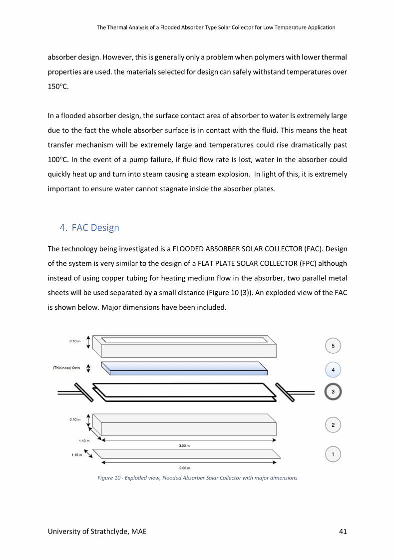
The Thermal Analysis of a Flooded Absorber Type Solar Collector for Low Temperature Application
University of Strathclyde, MAE 41
absorber design. However, this is generally only a problem when polymers with lower thermal
properties are used. the materials selected for design can safely withstand temperatures over
150oC.
In a flooded absorber design, the surface contact area of absorber to water is extremely large
due to the fact the whole absorber surface is in contact with the fluid. This means the heat
transfer mechanism will be extremely large and temperatures could rise dramatically past
100oC. In the event of a pump failure, if fluid flow rate is lost, water in the absorber could
quickly heat up and turn into steam causing a steam explosion. In light of this, it is extremely
important to ensure water cannot stagnate inside the absorber plates.
4. FAC Design The technology being investigated is a FLOODED ABSORBER SOLAR COLLECTOR (FAC). Design
of the system is very similar to the design of a FLAT PLATE SOLAR COLLECTOR (FPC) although
instead of using copper tubing for heating medium flow in the absorber, two parallel metal
sheets will be used separated by a small distance (Figure 10 (3)). An exploded view of the FAC
is shown below. Major dimensions have been included.
Figure 10 - Exploded view, Flooded Absorber Solar Collector with major dimensions
The Thermal Analysis of a Flooded Absorber Type Solar Collector for Low Temperature Application
University of Strathclyde, MAE 42
Numbers from Figure 10:
1. Base plate of exterior Casing
2. Main exterior casing
3. Flooded Absorber with inlet & outlet manifolds
4. Single glazed, clear float glass
5. Upper exterior frame
5. Model Description
5.1 Introduction When attempting to assess the performance characteristics of a Flooded Absorber type solar
collector, it was important to use a tool that would accurately simulate the outdoor
environment that the collector would perform in. ESP-r provides a virtual, natural atmosphere
in which almost any climate data can be simulated so was assumed as the ideal software. A
general model of a Flooded Absorber type solar collector was created in ESP-r.
5.2 Base Model Due to the fact the design of a Flooded absorber type solar collector has not been attempted,
the design of the system was based on a typical Flat Plate solar collector (Kalidasan & Srinivas,
2014). An exploded view of the model can be seen in Figure 10.
The main components of a typical flat plate solar collector are as follows:
• Black surface – incident solar radiation absorption system.
• Glazing cover – prevents radiant and heat losses from absorber surface, while
allowing radiation to contact the absorber.
• Manifold – to carry fluid in order to transfer thermal energy from the absorber.
• Support structure – to hold the system together and protect components from the
external.
• Insulation – covering sides and lower surfaces to reduce heat losses.
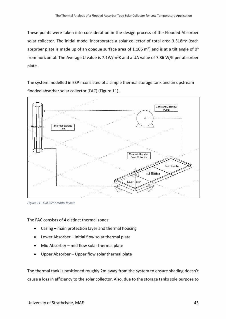
The Thermal Analysis of a Flooded Absorber Type Solar Collector for Low Temperature Application
University of Strathclyde, MAE 43
These points were taken into consideration in the design process of the Flooded Absorber
solar collector. The initial model incorporates a solar collector of total area 3.318m2 (each
absorber plate is made up of an opaque surface area of 1.106 m2) and is at a tilt angle of 0o
from horizontal. The Average U value is 7.1W/m2K and a UA value of 7.86 W/K per absorber
plate.
The system modelled in ESP-r consisted of a simple thermal storage tank and an upstream
flooded absorber solar collector (FAC) (Figure 11).
Figure 11 - Full ESP-r model layout
The FAC consists of 4 distinct thermal zones:
• Casing – main protection layer and thermal housing
• Lower Absorber – initial flow solar thermal plate
• Mid Absorber – mid flow solar thermal plate
• Upper Absorber – Upper flow solar thermal plate
The thermal tank is positioned roughly 2m away from the system to ensure shading doesn’t
cause a loss in efficiency to the solar collector. Also, due to the storage tanks sole purpose to
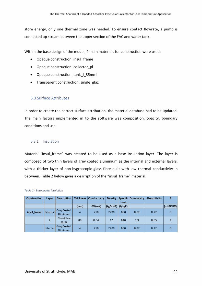
The Thermal Analysis of a Flooded Absorber Type Solar Collector for Low Temperature Application
University of Strathclyde, MAE 44
store energy, only one thermal zone was needed. To ensure contact flowrate, a pump is
connected up stream between the upper section of the FAC and water tank.
Within the base design of the model, 4 main materials for construction were used:
• Opaque construction: insul_frame
• Opaque construction: collector_pl
• Opaque construction: tank_i_35mmi
• Transparent construction: single_glaz
5.3 Surface Attributes
In order to create the correct surface attribution, the material database had to be updated.
The main factors implemented in to the software was composition, opacity, boundary
conditions and use.
5.3.1 Insulation
Material “insul_frame” was created to be used as a base insulation layer. The layer is
composed of two thin layers of grey coated aluminium as the internal and external layers,
with a thicker layer of non-hygroscopic glass fibre quilt with low thermal conductivity in
between. Table 2 below gives a description of the “insul_frame” material:
Table 2 - Base model insulation
Construction Layer Description Thickness Conductivity Density Specific Heat
Emmissivity Absorptivity R
(mm) (W/mK) (kg/m^3) (J/kgK) (m^2K/W)
insul_frame External Grey Coated Aliminium
4 210 2700 880 0.82 0.72 0
2 Glass Fibre Quilt
80 0.04 12 840 0.9 0.65 2
Internal Grey Coated Aliminium
4 210 2700 880 0.82 0.72 0
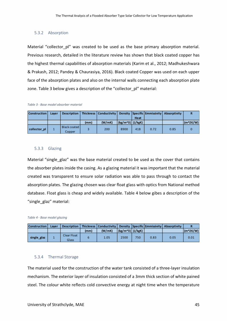
The Thermal Analysis of a Flooded Absorber Type Solar Collector for Low Temperature Application
University of Strathclyde, MAE 45
5.3.2 Absorption
Material “collector_pl” was created to be used as the base primary absorption material.
Previous research, detailed in the literature review has shown that black coated copper has
the highest thermal capabilities of absorption materials (Karim et al., 2012; Madhukeshwara
& Prakash, 2012; Pandey & Chaurasiya, 2016). Black coated Copper was used on each upper
face of the absorption plates and also on the internal walls connecting each absorption plate
zone. Table 3 below gives a description of the “collector_pl” material:
Table 3 - Base model absorber material
5.3.3 Glazing Material “single_glaz” was the base material created to be used as the cover that contains
the absorber plates inside the casing. As a glazing material it was important that the material
created was transparent to ensure solar radiation was able to pass through to contact the
absorption plates. The glazing chosen was clear float glass with optics from National method
database. Float glass is cheap and widely available. Table 4 below gibes a description of the
“single_glaz” material:
Table 4 - Base model glazing
5.3.4 Thermal Storage The material used for the construction of the water tank consisted of a three-layer insulation
mechanism. The exterior layer of insulation consisted of a 3mm thick section of white pained
steel. The colour white reflects cold convective energy at night time when the temperature
Construction Layer Description Thickness Conductivity Density Specific Heat
Emmissivity Absorptivity R
(mm) (W/mK) (kg/m^3) (J/kgK) (m^2K/W)
collector_pl 1 Black coated Copper
3 200 8900 418 0.72 0.85 0
Construction Layer Description Thickness Conductivity Density Specific Emmissivity Absorptivity R
(mm) (W/mK) (kg/m^3) (J/kgK) (m^2K/W)
single_glaz 1 Clear Float Glass
6 1.05 2500 750 0.83 0.05 0.01
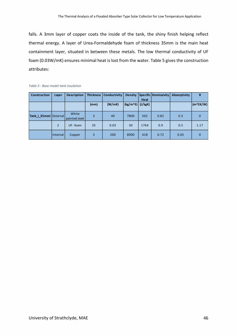
The Thermal Analysis of a Flooded Absorber Type Solar Collector for Low Temperature Application
University of Strathclyde, MAE 46
falls. A 3mm layer of copper coats the inside of the tank, the shiny finish helping reflect
thermal energy. A layer of Urea-Formaldehyde foam of thickness 35mm is the main heat
containment layer, situated in between these metals. The low thermal conductivity of UF
foam (0.03W/mK) ensures minimal heat is lost from the water. Table 5 gives the construction
attributes:
Table 5 - Base model tank insulation
Construction Layer Description Thickness Conductivity Density Specific
Heat
Emmissivity Absorptivity R
(mm) (W/mK) (kg/m^3) (J/kgK) (m^2K/W)
Tank_i_35mmi External White painted steel
3 40 7800 502 0.82 0.3 0
2 UF - foam 35 0.03 30 1764 0.9 0.5 1.17
Internal Copper 3 200 8900 418 0.72 0.65 0
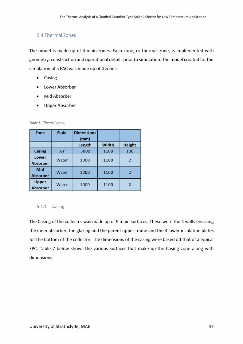
The Thermal Analysis of a Flooded Absorber Type Solar Collector for Low Temperature Application
University of Strathclyde, MAE 47
5.4 Thermal Zones
The model is made up of 4 main zones. Each zone, or thermal zone, is implemented with
geometry, construction and operational details prior to simulation. The model created for the
simulation of a FAC was made up of 4 zones:
• Casing
• Lower Absorber
• Mid Absorber
• Upper Absorber
Table 6 - Thermal zones
5.4.1 Casing
The Casing of the collector was made up of 9 main surfaces. These were the 4 walls encasing
the inner absorber, the glazing and the parent upper frame and the 3 lower insulation plates
for the bottom of the collector. The dimensions of the casing were based off that of a typical
FPC. Table 7 below shows the various surfaces that make up the Casing zone along with
dimensions:
Zone Fluid Dimensions (mm)
Length Width HeightCasing Air 3000 1100 100Lower
AbsorberWater 1000 1100 2
Mid Absorber
Water 1000 1100 2
Upper Absorber
Water 1000 1100 2
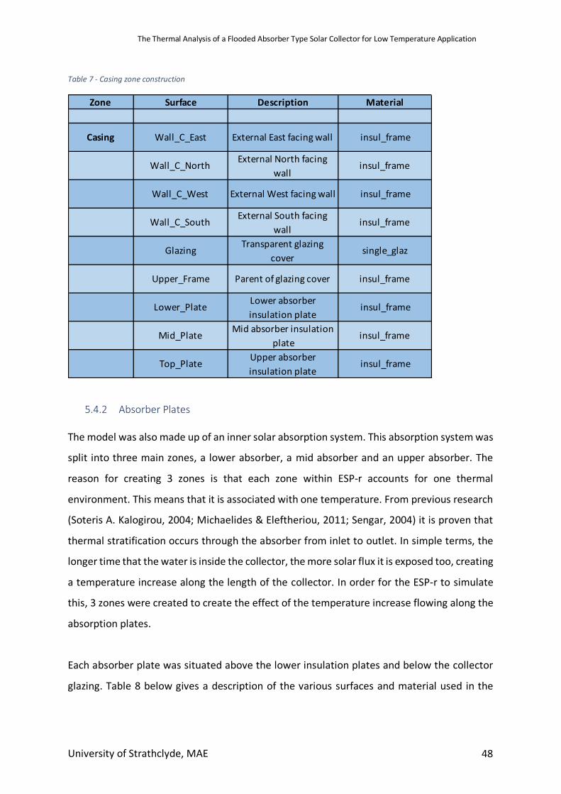
The Thermal Analysis of a Flooded Absorber Type Solar Collector for Low Temperature Application
University of Strathclyde, MAE 48
Table 7 - Casing zone construction
5.4.2 Absorber Plates
The model was also made up of an inner solar absorption system. This absorption system was
split into three main zones, a lower absorber, a mid absorber and an upper absorber. The
reason for creating 3 zones is that each zone within ESP-r accounts for one thermal
environment. This means that it is associated with one temperature. From previous research
(Soteris A. Kalogirou, 2004; Michaelides & Eleftheriou, 2011; Sengar, 2004) it is proven that
thermal stratification occurs through the absorber from inlet to outlet. In simple terms, the
longer time that the water is inside the collector, the more solar flux it is exposed too, creating
a temperature increase along the length of the collector. In order for the ESP-r to simulate
this, 3 zones were created to create the effect of the temperature increase flowing along the
absorption plates.
Each absorber plate was situated above the lower insulation plates and below the collector
glazing. Table 8 below gives a description of the various surfaces and material used in the
Zone Surface Description Material
Casing Wall_C_East External East facing wall insul_frame
Wall_C_North External North facing wall
insul_frame
Wall_C_West External West facing wall insul_frame
Wall_C_South External South facing wall
insul_frame
Glazing Transparent glazing cover
single_glaz
Upper_Frame Parent of glazing cover insul_frame
Lower_Plate Lower absorber insulation plate
insul_frame
Mid_Plate Mid absorber insulation plate
insul_frame
Top_Plate Upper absorber insulation plate
insul_frame
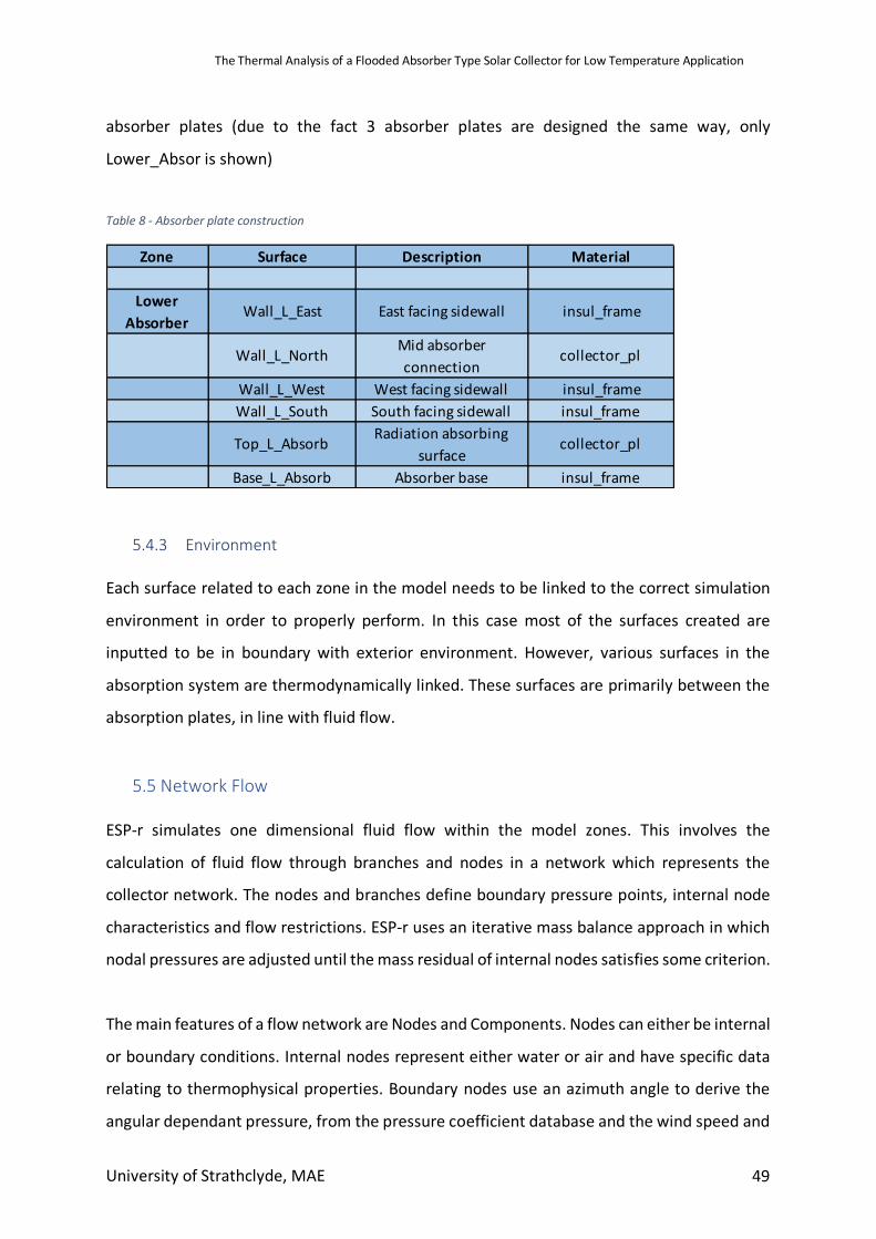
The Thermal Analysis of a Flooded Absorber Type Solar Collector for Low Temperature Application
University of Strathclyde, MAE 49
absorber plates (due to the fact 3 absorber plates are designed the same way, only
Lower_Absor is shown)
Table 8 - Absorber plate construction
5.4.3 Environment Each surface related to each zone in the model needs to be linked to the correct simulation
environment in order to properly perform. In this case most of the surfaces created are
inputted to be in boundary with exterior environment. However, various surfaces in the
absorption system are thermodynamically linked. These surfaces are primarily between the
absorption plates, in line with fluid flow.
5.5 Network Flow ESP-r simulates one dimensional fluid flow within the model zones. This involves the
calculation of fluid flow through branches and nodes in a network which represents the
collector network. The nodes and branches define boundary pressure points, internal node
characteristics and flow restrictions. ESP-r uses an iterative mass balance approach in which
nodal pressures are adjusted until the mass residual of internal nodes satisfies some criterion.
The main features of a flow network are Nodes and Components. Nodes can either be internal
or boundary conditions. Internal nodes represent either water or air and have specific data
relating to thermophysical properties. Boundary nodes use an azimuth angle to derive the
angular dependant pressure, from the pressure coefficient database and the wind speed and
Zone Surface Description Material
Lower Absorber
Wall_L_East East facing sidewall insul_frame
Wall_L_North Mid absorber connection
collector_pl
Wall_L_West West facing sidewall insul_frameWall_L_South South facing sidewall insul_frame
Top_L_Absorb Radiation absorbing surface
collector_pl
Base_L_Absorb Absorber base insul_frame
The Thermal Analysis of a Flooded Absorber Type Solar Collector for Low Temperature Application
University of Strathclyde, MAE 50
direction at a certain point in time within the simulation. Additional internal nodes can be
implemented to give control e.g. an extra node in order to connect a component in series.
Components are related to the flow regime, for example a pump.
Within the design of the FAC, there are two flow networks relating to water and air.
5.5.1 Water Network The water network is the main flow network within the ESP-r model. It simulates the water
flowing through the absorber plates and is the main focus of investigation.
5.5.1.1 Nodes In the model created there are three main nodes situated in each of the absorber plates
(Lower, mid and top absorber plates). This is so the change in temperature can be accurately
measured as the water passes through the collector. The temperature associated with each
node is the temperature assumed at the start of the simulation. As these internal nodes are
part of the thermal model, the temperature is updated with calculated values as the
simulation progresses. Having three zones accurately models the increase in temperature. If
there was just one zone there would be no temperature change through the absorber as
zones are associated with just one temperature only. To increase the accuracy of the
simulation, more zones could be created in order to have a smoother increase in temperature
as the water flows from zone to zone. For this simulation, however, 3 zones were deemed
satisfactory.
Each node also has a height attribute above some arbitrary datum which is used to support
buoyancy calculations. Due to the collector angle tilt being 0o, each node is at 0.001m (middle
of the absorber plate, where water flows).
5.5.1.2 Components
Within the water network there are two main components:
• Absorber Pump (Abs_Pump)
The Thermal Analysis of a Flooded Absorber Type Solar Collector for Low Temperature Application
University of Strathclyde, MAE 51
• Nodal Linkage (Abs_Link)
The pump is implemented as a constant mass flowrate inducer and follows the simple mass
flowrate equation:
𝑚 = 𝐴
Where:
• 𝐴 = 𝑥 − 𝑠𝑒𝑐𝑡𝑖𝑜𝑛𝑎𝑙𝑎𝑟𝑒𝑎(𝑚R)
The nodal linkage is simply used to connect nodes within the absorber and to the pump.
Abs_link is a general flow conduit (pipe) which accounts for frictional and dynamic losses
assuming the following: no pressure gain from a pump, a uniform cross-section and steady
state conditions. The mass flowrate equation takes the form:
𝑚 = 𝜌 ∗ 𝑓(𝐷, 𝐴, 𝐿, 𝑆𝐶𝑖)
Where:
• 𝜌 = 𝑑𝑒𝑛𝑠𝑖𝑡𝑦 lmnopq
• 𝐷 = 𝑑𝑖𝑎𝑚𝑒𝑡𝑒𝑟(𝑚)
• 𝐴 = 𝑥 − 𝑠𝑒𝑐𝑡𝑖𝑜𝑛𝑎𝑙𝑎𝑟𝑒𝑎(𝑚R)
• 𝐿 = 𝑙𝑒𝑛𝑔𝑡ℎ(𝑚)
• 𝑆𝐶𝑖 = 𝑠𝑢𝑚𝑜𝑓𝑙𝑜𝑐𝑎𝑙𝑑𝑦𝑛𝑎𝑚𝑖𝑐𝑙𝑜𝑠𝑠𝑓𝑎𝑐𝑡𝑜𝑟𝑠(n/a)
5.5.2 Air Network
The airflow network is primarily included to induce external losses due to wind effects. If there
was no air flow to the system, the simulation would be largely redundant as would not
accurately model the outdoor environment.
5.5.2.1 Nodes
The Thermal Analysis of a Flooded Absorber Type Solar Collector for Low Temperature Application
University of Strathclyde, MAE 52
The air network consists of only 2 nodes, an internal node and a boundary node. The internal
node represents the casing thermal zone (casing, glazing, under panels), while the boundary
node represents the wind pressure. The pressure of the node is generated by wind impinging
upon a surface. The pressure is a function of wind velocity, wind direction and pressure
coefficient (Cp – assigned based on the orientation and geometry of the surface). In the FAC
model, the pressure coefficient is set to that of a semi exposed wall.
5.5.2.2 Components
The only component related to the air flow network is the Frame Crack. This emulates the
fact that the collector is not 100% air tight. The simple mass flowrate equation is as follows:
𝑚 = 𝜌 ∗ 𝑓(𝑊, 𝐿, 𝑑𝑃)
Where:
• 𝜌 = 𝑑𝑒𝑛𝑠𝑖𝑡𝑦 lmnopq
• 𝑊 = 𝑤𝑖𝑑𝑡ℎ(𝑚)
• 𝑑𝑃 = 𝑝𝑟𝑒𝑠𝑠𝑢𝑟𝑒𝑑𝑖𝑓𝑓𝑒𝑟𝑒𝑛𝑐𝑒(𝑃𝑎)
When inputting the Length of the airflow crack, a length roughly the perimeter of the collector
casing was chosen to consider the fact there could be leakages all the way around the model.
5.5.3 Control System In order to ensure energy was not wasted when external temperatures cooled through the
simulation period, a control system was implemented. The simple, direct control system is
connected to thermal storage tank and the upper absorption plate. When the temperature
of the absorber plate surface rises greater than 3oC compared to the water tank, the pumped
connected between the upper absorber and water tank is actuated. When the temperature
of the absorber plate falls within 3oC, the pump is turned off and the storage tank holds the
heated water. The idea behind this control system is to ensure when the collector area starts
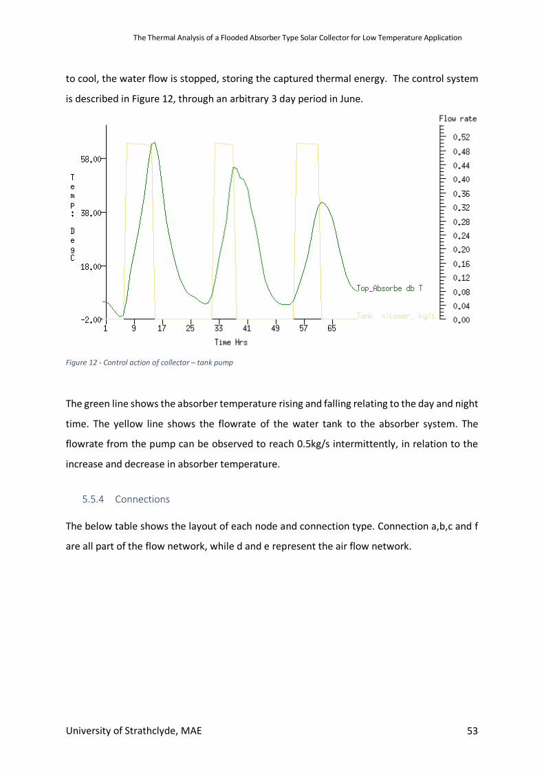
The Thermal Analysis of a Flooded Absorber Type Solar Collector for Low Temperature Application
University of Strathclyde, MAE 53
to cool, the water flow is stopped, storing the captured thermal energy. The control system
is described in Figure 12, through an arbitrary 3 day period in June.
Figure 12 - Control action of collector – tank pump
The green line shows the absorber temperature rising and falling relating to the day and night
time. The yellow line shows the flowrate of the water tank to the absorber system. The
flowrate from the pump can be observed to reach 0.5kg/s intermittently, in relation to the
increase and decrease in absorber temperature.
5.5.4 Connections
The below table shows the layout of each node and connection type. Connection a,b,c and f
are all part of the flow network, while d and e represent the air flow network.
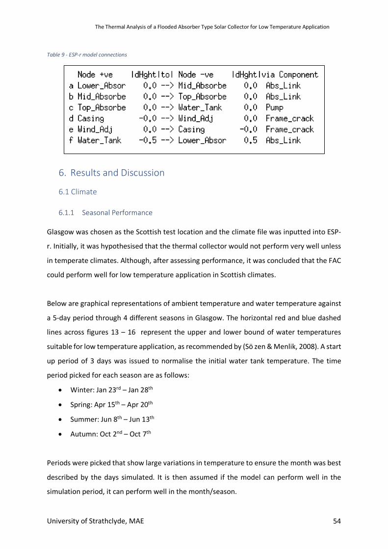
The Thermal Analysis of a Flooded Absorber Type Solar Collector for Low Temperature Application
University of Strathclyde, MAE 54
Table 9 - ESP-r model connections
6. Results and Discussion
6.1 Climate
6.1.1 Seasonal Performance Glasgow was chosen as the Scottish test location and the climate file was inputted into ESP-
r. Initially, it was hypothesised that the thermal collector would not perform very well unless
in temperate climates. Although, after assessing performance, it was concluded that the FAC
could perform well for low temperature application in Scottish climates.
Below are graphical representations of ambient temperature and water temperature against
a 5-day period through 4 different seasons in Glasgow. The horizontal red and blue dashed
lines across figures 13 – 16 represent the upper and lower bound of water temperatures
suitable for low temperature application, as recommended by (Sö zen & Menlik, 2008). A start
up period of 3 days was issued to normalise the initial water tank temperature. The time
period picked for each season are as follows:
• Winter: Jan 23rd – Jan 28th
• Spring: Apr 15th – Apr 20th
• Summer: Jun 8th – Jun 13th
• Autumn: Oct 2nd – Oct 7th
Periods were picked that show large variations in temperature to ensure the month was best
described by the days simulated. It is then assumed if the model can perform well in the
simulation period, it can perform well in the month/season.
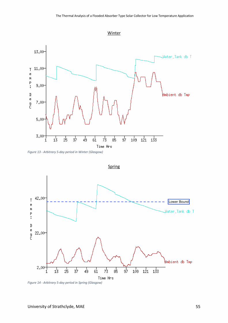
The Thermal Analysis of a Flooded Absorber Type Solar Collector for Low Temperature Application
University of Strathclyde, MAE 55
Winter
Figure 13 - Arbitrary 5-day period in Winter (Glasgow)
Spring
Figure 14 - Arbitrary 5-day period in Spring (Glasgow)
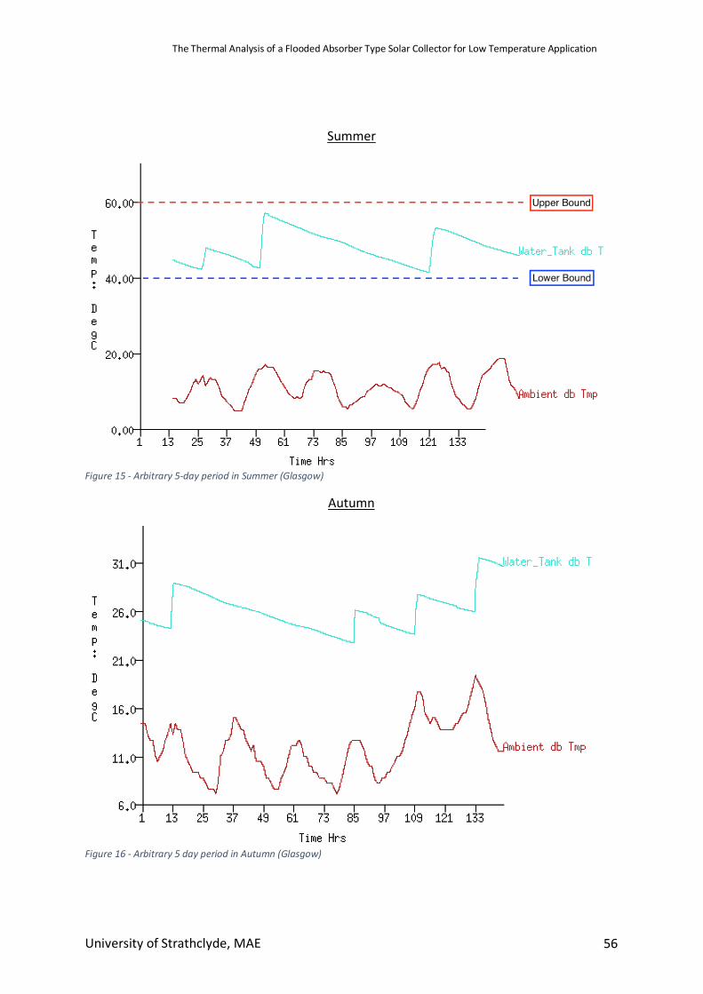
The Thermal Analysis of a Flooded Absorber Type Solar Collector for Low Temperature Application
University of Strathclyde, MAE 56
Summer
Figure 15 - Arbitrary 5-day period in Summer (Glasgow)
Autumn
Figure 16 - Arbitrary 5 day period in Autumn (Glasgow)
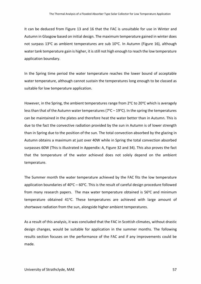
The Thermal Analysis of a Flooded Absorber Type Solar Collector for Low Temperature Application
University of Strathclyde, MAE 57
It can be deduced from Figure 13 and 16 that the FAC is unsuitable for use in Winter and
Autumn in Glasgow based on initial design. The maximum temperature gained in winter does
not surpass 13oC as ambient temperatures are sub 10oC. In Autumn (Figure 16), although
water tank temperature gain is higher, it is still not high enough to reach the low temperature
application boundary.
In the Spring time period the water temperature reaches the lower bound of acceptable
water temperature, although cannot sustain the temperatures long enough to be classed as
suitable for low temperature application.
However, in the Spring, the ambient temperatures range from 2oC to 20oC which is averagely
less than that of the Autumn water temperatures (7oC – 19oC). In the spring the temperatures
can be maintained in the plates and therefore heat the water better than in Autumn. This is
due to the fact the convective radiation provided by the sun in Autumn is of lower strength
than in Spring due to the position of the sun. The total convection absorbed by the glazing in
Autumn obtains a maximum at just over 40W while in Spring the total convection absorbed
surpasses 60W (This is illustrated in Appendix: A, Figure 32 and 34). This also proves the fact
that the temperature of the water achieved does not solely depend on the ambient
temperature.
The Summer month the water temperature achieved by the FAC fits the low temperature
application boundaries of 40oC – 60oC. This is the result of careful design procedure followed
from many research papers. The max water temperature obtained is 56oC and minimum
temperature obtained 41oC. These temperatures are achieved with large amount of
shortwave radiation from the sun, alongside higher ambient temperatures.
As a result of this analysis, it was concluded that the FAC in Scottish climates, without drastic
design changes, would be suitable for application in the summer months. The following
results section focuses on the performance of the FAC and if any improvements could be
made.

The Thermal Analysis of a Flooded Absorber Type Solar Collector for Low Temperature Application
University of Strathclyde, MAE 58
6.2 Modifications to Base Model
The base case design of the FAC was based off of various papers, detailing the design
considerations for the FPC due to the fact there are no previous designs of a FAC. Therefore,
the design may have features which could be improved upon. In this section, various aspects
of the FAC will be altered and simulated in ESP-r to find the design with best thermal
performance. The aspects that will be focused on include:
• Absorber plate spacing
• Glazing
• Pump flowrate
• Thermal tank size
• Insulation
6.3 Design Objective
The main design objectives are as follows:
• For low temperature application, water is required at 60oC with a minimum of 40oC
(Sö zen & Menlik, 2008). Therefore, the design must average a water temperature of
50oC, to ensure hot water is accessible. The optimal design shall provide water no
hotter than 60oC and no colder than 40oC.
• A large factor that hinders the production of the FPC is design complexity. Simplicity
of design is of high priority and where possible will be simplified.
6.4 Base Model
6.4.1 Temperature Distribution The temperature distribution across the flooded absorber is important for efficiency as un-
even temperature distribution can result in lower water temperature gain. As previously
mentioned, this is a real problem experienced by the conventional parallel tube FPC. Below is
a graph of lower, mid and upper absorber plates:
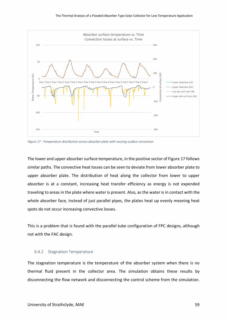
The Thermal Analysis of a Flooded Absorber Type Solar Collector for Low Temperature Application
University of Strathclyde, MAE 59
Figure 17 - Temperature distribution across absorber plate with varying surface convection
The lower and upper absorber surface temperature, in the positive sector of Figure 17 follows
similar paths. The convective heat losses can be seen to deviate from lower absorber plate to
upper absorber plate. The distribution of heat along the collector from lower to upper
absorber is at a constant, increasing heat transfer efficiency as energy is not expended
traveling to areas in the plate where water is present. Also, as the water is in contact with the
whole absorber face, instead of just parallel pipes, the plates heat up evenly meaning heat
spots do not occur increasing convective losses.
This is a problem that is found with the parallel tube configuration of FPC designs, although
not with the FAC design.
6.4.2 Stagnation Temperature The stagnation temperature is the temperature of the absorber system when there is no
thermal fluid present in the collector area. The simulation obtains these results by
disconnecting the flow network and disconnecting the control scheme from the simulation.
-300
-200
-100
0
100
200
300
-150
-100
-50
0
50
100
Day 1 Day 1 Day 1 Day 2 Day 2 Day 2 Day 3 Day 3 Day 3 Day 4 Day 4 Day 4 Day 5 Day 5 Day 5 Day 6 Day 6
Conv
ectio
n at
surfa
ce (W
)
Wat
er T
empe
ratu
re (o
C)
Time
Absorber surface temperature vs. TimeConvection losses at surface vs. Time
Lower Absorber (oC)
Upper Absorber (oC)
Low abs surf conv (W)
Upper abs surf conv (W)
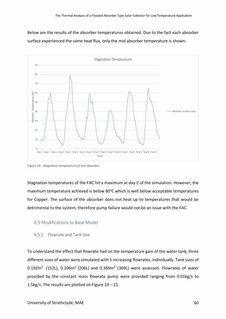
The Thermal Analysis of a Flooded Absorber Type Solar Collector for Low Temperature Application
University of Strathclyde, MAE 60
Below are the results of the absorber temperatures obtained. Due to the fact each absorber
surface experienced the same heat flux, only the mid absorber temperature is shown:
Figure 18 - Stagnation temperature of mid absorber
Stagnation temperatures of the FAC hit a maximum at day 2 of the simulation. However, the
maximum temperature achieved is below 80oC which is well below acceptable temperatures
for Copper. The surface of the absorber does not heat up to temperatures that would be
detrimental to the system, therefore pump failure would not be an issue with the FAC.
6.5 Modifications to Base Model
6.5.1 Flowrate and Tank Size
To understand the effect that flowrate had on the temperature gain of the water tank, three
different sizes of water were simulated with 5 increasing flowrates, individually. Tank sizes of
0.152m3 (152L), 0.206m3 (206L) and 0.369m3 (369L) were assessed. Flowrates of water
provided by the constant mass flowrate pump were provided ranging from 0.01kg/s to
1.5kg/s. The results are plotted on Figure 19 – 21.
0
10
20
30
40
50
60
70
80
90
Day 1 Day 1 Day 1 Day 2 Day 2 Day 2 Day 3 Day 3 Day 3 Day 4 Day 4 Day 4 Day 5 Day 5 Day 5 Day 6 Day 6
Abso
rber
Tem
pera
ture
(oC)
Time
Stagnation Temperature
Absorber surface temp
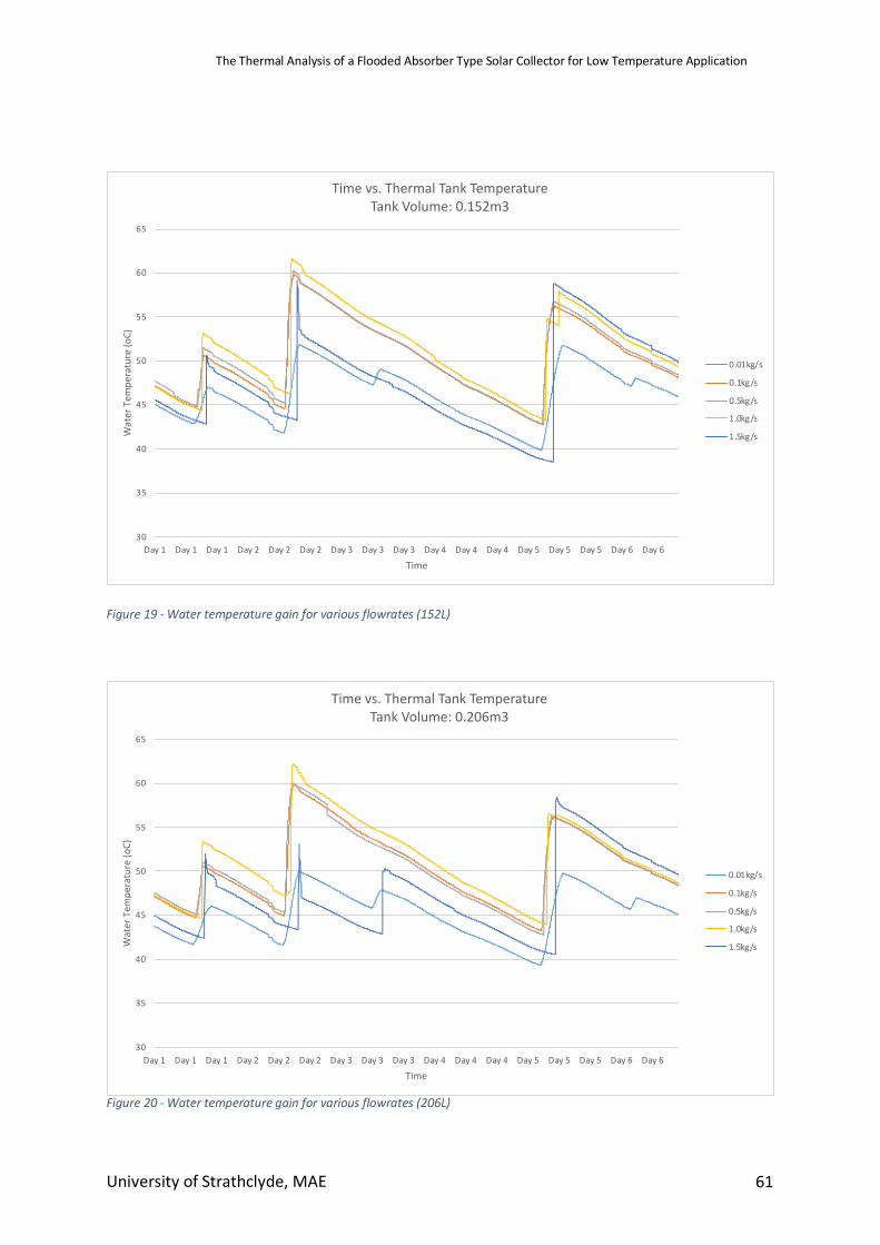
The Thermal Analysis of a Flooded Absorber Type Solar Collector for Low Temperature Application
University of Strathclyde, MAE 61
Figure 19 - Water temperature gain for various flowrates (152L)
Figure 20 - Water temperature gain for various flowrates (206L)
30
35
40
45
50
55
60
65
Day 1 Day 1 Day 1 Day 2 Day 2 Day 2 Day 3 Day 3 Day 3 Day 4 Day 4 Day 4 Day 5 Day 5 Day 5 Day 6 Day 6
Wat
er T
empe
ratu
re (o
C)
Time
Time vs. Thermal Tank TemperatureTank Volume: 0.152m3
0.01kg/s
0.1kg/s
0.5kg/s
1.0kg/s
1.5kg/s
30
35
40
45
50
55
60
65
Day 1 Day 1 Day 1 Day 2 Day 2 Day 2 Day 3 Day 3 Day 3 Day 4 Day 4 Day 4 Day 5 Day 5 Day 5 Day 6 Day 6
Wat
er T
empe
ratu
re (o
C)
Time
Time vs. Thermal Tank TemperatureTank Volume: 0.206m3
0.01kg/s
0.1kg/s
0.5kg/s
1.0kg/s
1.5kg/s
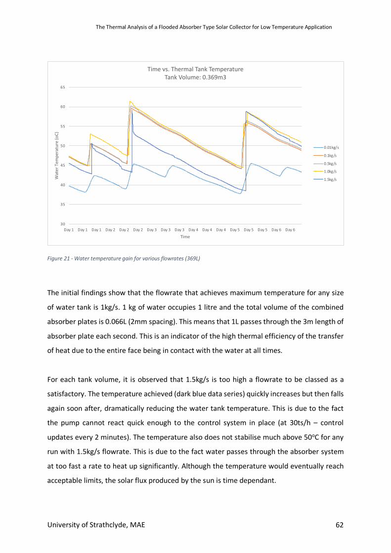
The Thermal Analysis of a Flooded Absorber Type Solar Collector for Low Temperature Application
University of Strathclyde, MAE 62
Figure 21 - Water temperature gain for various flowrates (369L)
The initial findings show that the flowrate that achieves maximum temperature for any size
of water tank is 1kg/s. 1 kg of water occupies 1 litre and the total volume of the combined
absorber plates is 0.066L (2mm spacing). This means that 1L passes through the 3m length of
absorber plate each second. This is an indicator of the high thermal efficiency of the transfer
of heat due to the entire face being in contact with the water at all times.
For each tank volume, it is observed that 1.5kg/s is too high a flowrate to be classed as a
satisfactory. The temperature achieved (dark blue data series) quickly increases but then falls
again soon after, dramatically reducing the water tank temperature. This is due to the fact
the pump cannot react quick enough to the control system in place (at 30ts/h – control
updates every 2 minutes). The temperature also does not stabilise much above 50oC for any
run with 1.5kg/s flowrate. This is due to the fact water passes through the absorber system
at too fast a rate to heat up significantly. Although the temperature would eventually reach
acceptable limits, the solar flux produced by the sun is time dependant.
30
35
40
45
50
55
60
65
Day 1 Day 1 Day 1 Day 2 Day 2 Day 2 Day 3 Day 3 Day 3 Day 4 Day 4 Day 4 Day 5 Day 5 Day 5 Day 6 Day 6
Wat
er T
empe
ratu
re (o
C)
Time
Time vs. Thermal Tank TemperatureTank Volume: 0.369m3
0.01kg/s
0.1kg/s
0.5kg/s
1.0kg/s
1.5kg/s
The Thermal Analysis of a Flooded Absorber Type Solar Collector for Low Temperature Application
University of Strathclyde, MAE 63
A similar but opposite situation results from a flowrate of 0.01kg/s. For increasing tank size,
the average temperature can be seen to drop from 46.2oC in the 152l tank to 45.1oC in the
206L tank and then 42.0oC in the large 369L tank. This can be explained due to the increasing
amount of water in the tank that the low flowrate needs to heat. As the tank size increases,
the heated water begins to have less effect on the bulk temperature. The lower flowrate also
means the temperature increase is slower.
In section 2.4.2, according to (DEFRA, 2013), the average household uses 349 litres of water
each day in the UK. Therefore, if the system was to be used in a common household, a tank
size of 369 litres would provide sufficient hot water coupled to the FAC, with a 20-litre safety
margin.
When determining optimum flowrate, a low flowrate is desirable due to less energy being
needed by the pumping system. In Figure 21 (369L), for the 5 day period, 0.1kg/s, 0.5kg/s and
1.0kg/s all achieve similar results, however at two events in graph (day 1 & day 5) the
temperature can be seen to gain 3-4oC by the 1kg/s. However, all three flowrates stay in the
acceptable bounds for low temperature application 40-60oC. Therefore, for a 369L tank size,
a 0.1kg/s flowrate is chosen.
The flowrate of 0.1kg/s and the effect on the 369L water tank temperature can be observed
in Figure 22. The pump is only activated for short periods of time as the water is heated rapidly
through the FAC.
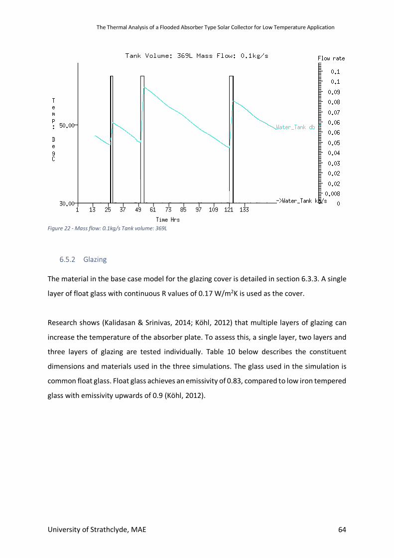
The Thermal Analysis of a Flooded Absorber Type Solar Collector for Low Temperature Application
University of Strathclyde, MAE 64
Figure 22 - Mass flow: 0.1kg/s Tank volume: 369L
6.5.2 Glazing The material in the base case model for the glazing cover is detailed in section 6.3.3. A single
layer of float glass with continuous R values of 0.17 W/m2K is used as the cover.
Research shows (Kalidasan & Srinivas, 2014; Köhl, 2012) that multiple layers of glazing can
increase the temperature of the absorber plate. To assess this, a single layer, two layers and
three layers of glazing are tested individually. Table 10 below describes the constituent
dimensions and materials used in the three simulations. The glass used in the simulation is
common float glass. Float glass achieves an emissivity of 0.83, compared to low iron tempered
glass with emissivity upwards of 0.9 (Köhl, 2012).
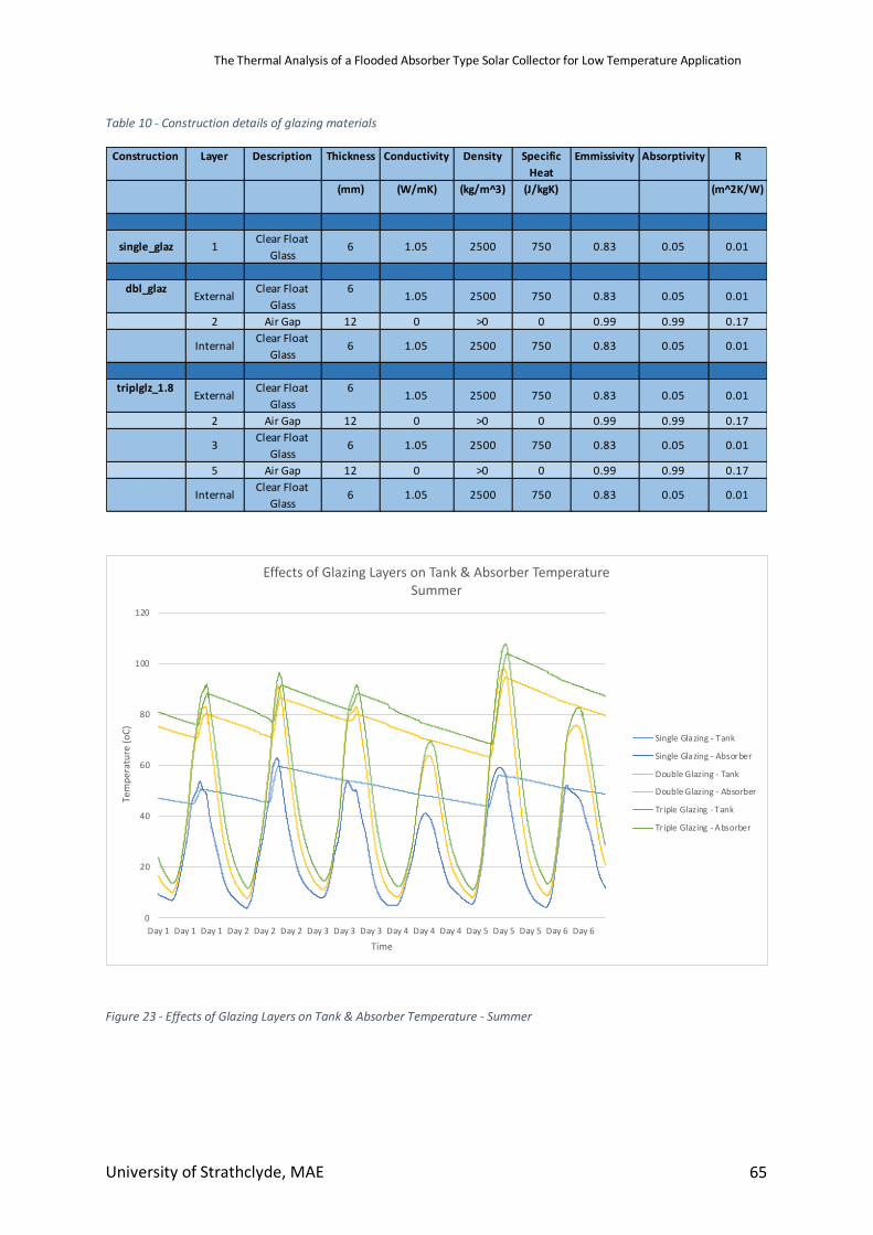
The Thermal Analysis of a Flooded Absorber Type Solar Collector for Low Temperature Application
University of Strathclyde, MAE 65
Table 10 - Construction details of glazing materials
Figure 23 - Effects of Glazing Layers on Tank & Absorber Temperature - Summer
Construction Layer Description Thickness Conductivity Density Specific Heat
Emmissivity Absorptivity R
(mm) (W/mK) (kg/m^3) (J/kgK) (m^2K/W)
single_glaz 1 Clear Float Glass
6 1.05 2500 750 0.83 0.05 0.01
dbl_glaz External Clear Float Glass
6 1.05 2500 750 0.83 0.05 0.01
2 Air Gap 12 0 >0 0 0.99 0.99 0.17
Internal Clear Float Glass
6 1.05 2500 750 0.83 0.05 0.01
triplglz_1.8 External Clear Float Glass
6 1.05 2500 750 0.83 0.05 0.01
2 Air Gap 12 0 >0 0 0.99 0.99 0.17
3 Clear Float Glass
6 1.05 2500 750 0.83 0.05 0.01
5 Air Gap 12 0 >0 0 0.99 0.99 0.17
Internal Clear Float Glass
6 1.05 2500 750 0.83 0.05 0.01
0
20
40
60
80
100
120
Day 1 Day 1 Day 1 Day 2 Day 2 Day 2 Day 3 Day 3 Day 3 Day 4 Day 4 Day 4 Day 5 Day 5 Day 5 Day 6 Day 6
Te
mp
era
ture
(o
C)
Time
Effects of Glazing Layers on Tank & Absorber Temperature
Summer
Single Glazing - Tank
Single Glazing - Absorber
Double Glazing - Tank
Double Glazing - Absorber
Tr iple Glazing - Tank
Triple Glazing - Absorber
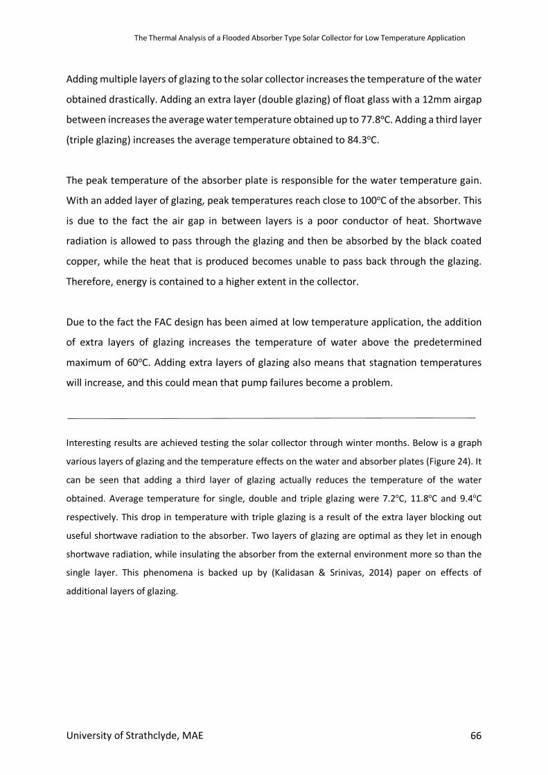
The Thermal Analysis of a Flooded Absorber Type Solar Collector for Low Temperature Application
University of Strathclyde, MAE 66
Adding multiple layers of glazing to the solar collector increases the temperature of the water
obtained drastically. Adding an extra layer (double glazing) of float glass with a 12mm airgap
between increases the average water temperature obtained up to 77.8oC. Adding a third layer
(triple glazing) increases the average temperature obtained to 84.3oC.
The peak temperature of the absorber plate is responsible for the water temperature gain.
With an added layer of glazing, peak temperatures reach close to 100oC of the absorber. This
is due to the fact the air gap in between layers is a poor conductor of heat. Shortwave
radiation is allowed to pass through the glazing and then be absorbed by the black coated
copper, while the heat that is produced becomes unable to pass back through the glazing.
Therefore, energy is contained to a higher extent in the collector.
Due to the fact the FAC design has been aimed at low temperature application, the addition
of extra layers of glazing increases the temperature of water above the predetermined
maximum of 60oC. Adding extra layers of glazing also means that stagnation temperatures
will increase, and this could mean that pump failures become a problem.
Interesting results are achieved testing the solar collector through winter months. Below is a graph
various layers of glazing and the temperature effects on the water and absorber plates (Figure 24). It
can be seen that adding a third layer of glazing actually reduces the temperature of the water
obtained. Average temperature for single, double and triple glazing were 7.2oC, 11.8oC and 9.4oC
respectively. This drop in temperature with triple glazing is a result of the extra layer blocking out
useful shortwave radiation to the absorber. Two layers of glazing are optimal as they let in enough
shortwave radiation, while insulating the absorber from the external environment more so than the
single layer. This phenomena is backed up by (Kalidasan & Srinivas, 2014) paper on effects of
additional layers of glazing.
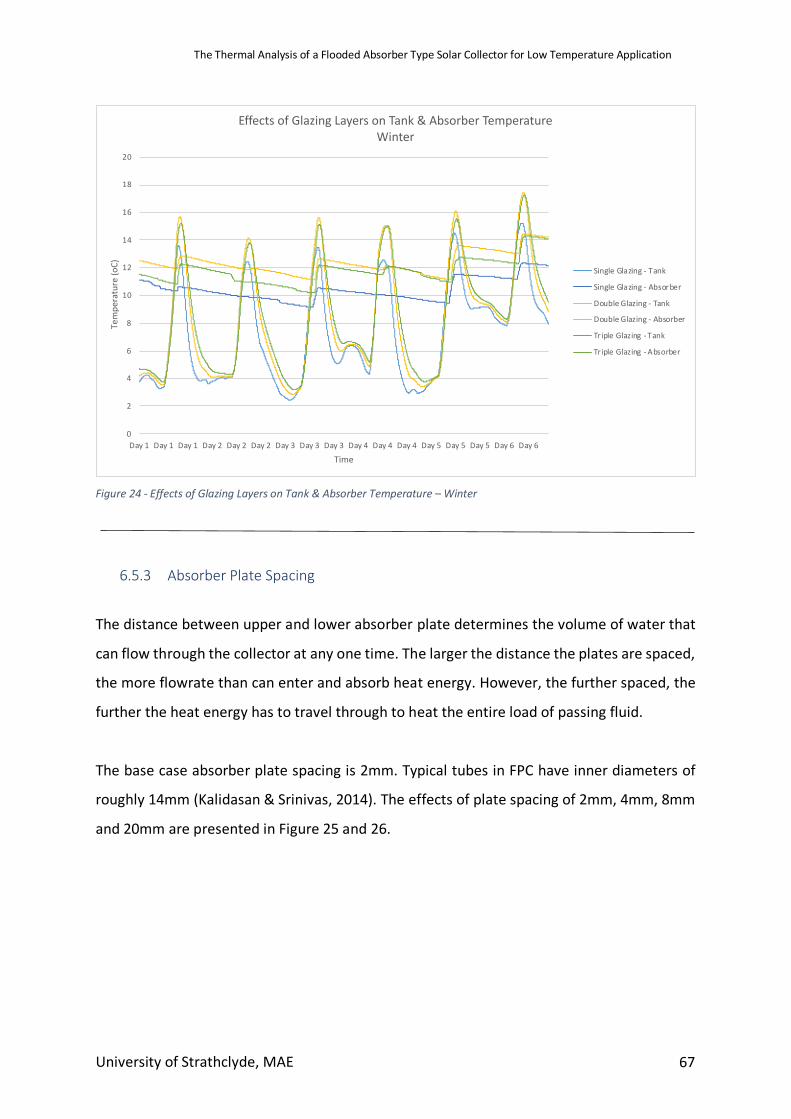
The Thermal Analysis of a Flooded Absorber Type Solar Collector for Low Temperature Application
University of Strathclyde, MAE 67
Figure 24 - Effects of Glazing Layers on Tank & Absorber Temperature – Winter
6.5.3 Absorber Plate Spacing
The distance between upper and lower absorber plate determines the volume of water that
can flow through the collector at any one time. The larger the distance the plates are spaced,
the more flowrate than can enter and absorb heat energy. However, the further spaced, the
further the heat energy has to travel through to heat the entire load of passing fluid.
The base case absorber plate spacing is 2mm. Typical tubes in FPC have inner diameters of
roughly 14mm (Kalidasan & Srinivas, 2014). The effects of plate spacing of 2mm, 4mm, 8mm
and 20mm are presented in Figure 25 and 26.
0
2
4
6
8
10
12
14
16
18
20
Day 1 Day 1 Day 1 Day 2 Day 2 Day 2 Day 3 Day 3 Day 3 Day 4 Day 4 Day 4 Day 5 Day 5 Day 5 Day 6 Day 6
Tem
pera
ture
(oC)
Time
Effects of Glazing Layers on Tank & Absorber TemperatureWinter
Single Glazing - Tank
Single Glazing - Absorber
Double Glazing - Tank
Double Glazing - Absorber
Tr iple Glazing - Tank
Triple Glazing - Absorber
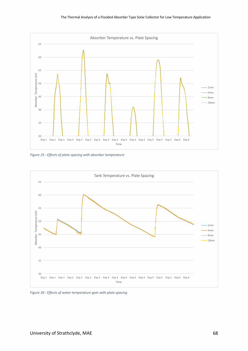
The Thermal Analysis of a Flooded Absorber Type Solar Collector for Low Temperature Application
University of Strathclyde, MAE 68
Figure 25 - Effects of plate spacing with absorber temperature
Figure 26 - Effects of water temperature gain with plate spacing
30
35
40
45
50
55
60
65
Day 1 Day 1 Day 1 Day 2 Day 2 Day 2 Day 3 Day 3 Day 3 Day 4 Day 4 Day 4 Day 5 Day 5 Day 5 Day 6 Day 6
Abso
rber
Tem
pera
ture
(oC)
Time
Absorber Temperature vs. Plate Spacing
2mm
4mm
8mm
20mm
30
35
40
45
50
55
60
65
Day 1 Day 1 Day 1 Day 2 Day 2 Day 2 Day 3 Day 3 Day 3 Day 4 Day 4 Day 4 Day 5 Day 5 Day 5 Day 6 Day 6
Abso
rber
Tem
pera
ture
(oC)
Time
Tank Temperature vs. Plate Spacing
2mm
4mm
8mm
20mm
The Thermal Analysis of a Flooded Absorber Type Solar Collector for Low Temperature Application
University of Strathclyde, MAE 69
Results show no real difference to temperature gain with absorber plate spacing from 2mm
– 20mm. Absorber temperatures vary almost identically while water temperature gains vary
to a maximum of 1oC. It can be concluded that absorber plate spacing is not a strict variable.
This means that simplicity of design is increased. Complex measurements are not needed in
order to correctly space the collector plates. Ensuring the plates are not in contact but within
20mm of each other will produce specific water temperatures for low temperature
application.
6.5.4 Insulation
The casing and surrounding material of the FAC is constructed from two aluminium layers,
with glass fibre layer sandwiched in between. Details of the construction, termed
“insul_frame”, are displayed in Table 11
In order to assess the importance of insulation to the design and the different possibilities
with insulation, 3 alternatives to the base insulation design were trialled:
• Increased thickness of insulation layer
• Glass wool (Sengar, 2004)
• Air gap – vacuum insulation (El-Sherbiny et al., 1978)
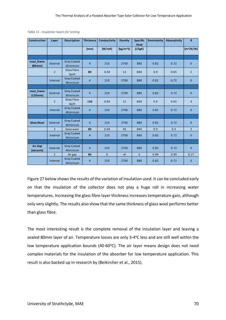
The Thermal Analysis of a Flooded Absorber Type Solar Collector for Low Temperature Application
University of Strathclyde, MAE 70
Table 11 - Insulation layers for testing
Figure 27 below shows the results of the variation of insulation used. It can be concluded early
on that the insulation of the collector does not play a huge roll in increasing water
temperatures. Increasing the glass fibre layer thickness increases temperature gain, although
only very slightly. The results also show that the same thickness of glass wool performs better
than glass fibre.
The most interesting result is the complete removal of the insulation layer and leaving a
sealed 80mm layer of air. Temperature losses are only 3-4oC less and are still well within the
low temperature application bounds (40-60oC). The air layer means design does not need
complex materials for the insulation of the absorber for low temperature application. This
result is also backed up in research by (Beikircher et al., 2015).
Construction Layer Description Thickness Conductivity Density Specific Heat
Emmissivity Absorptivity R
(mm) (W/mK) (kg/m^3) (J/kgK) (m^2K/W)
insul_frame (80mm)
External Grey Coated Aliminium
4 210 2700 880 0.82 0.72 0
2 Glass Fibre Quilt
80 0.04 12 840 0.9 0.65 2
Internal Grey Coated Aliminium
4 210 2700 880 0.82 0.72 0
insul_frame (120mm)
External Grey Coated Aliminium
4 210 2700 880 0.82 0.72 0
2 Glass Fibre Quilt
120 0.04 12 840 0.9 0.65 3
Internal Grey Coated Aliminium
4 210 2700 880 0.82 0.72 0
Glass Wool External Grey Coated Aliminium
4 210 2700 880 0.82 0.72 0
2 Glass wool 80 0.04 30 840 0.9 0.3 3
Internal Grey Coated Aliminium
4 210 2700 880 0.82 0.72 0
Air Gap (vacuum)
External Grey Coated Aliminium
4 210 2700 880 0.82 0.72 0
2 Air gap 80 0 >0 0 0.99 0.99 0.17
Internal Grey Coated Aliminium
4 210 2700 880 0.82 0.72 0
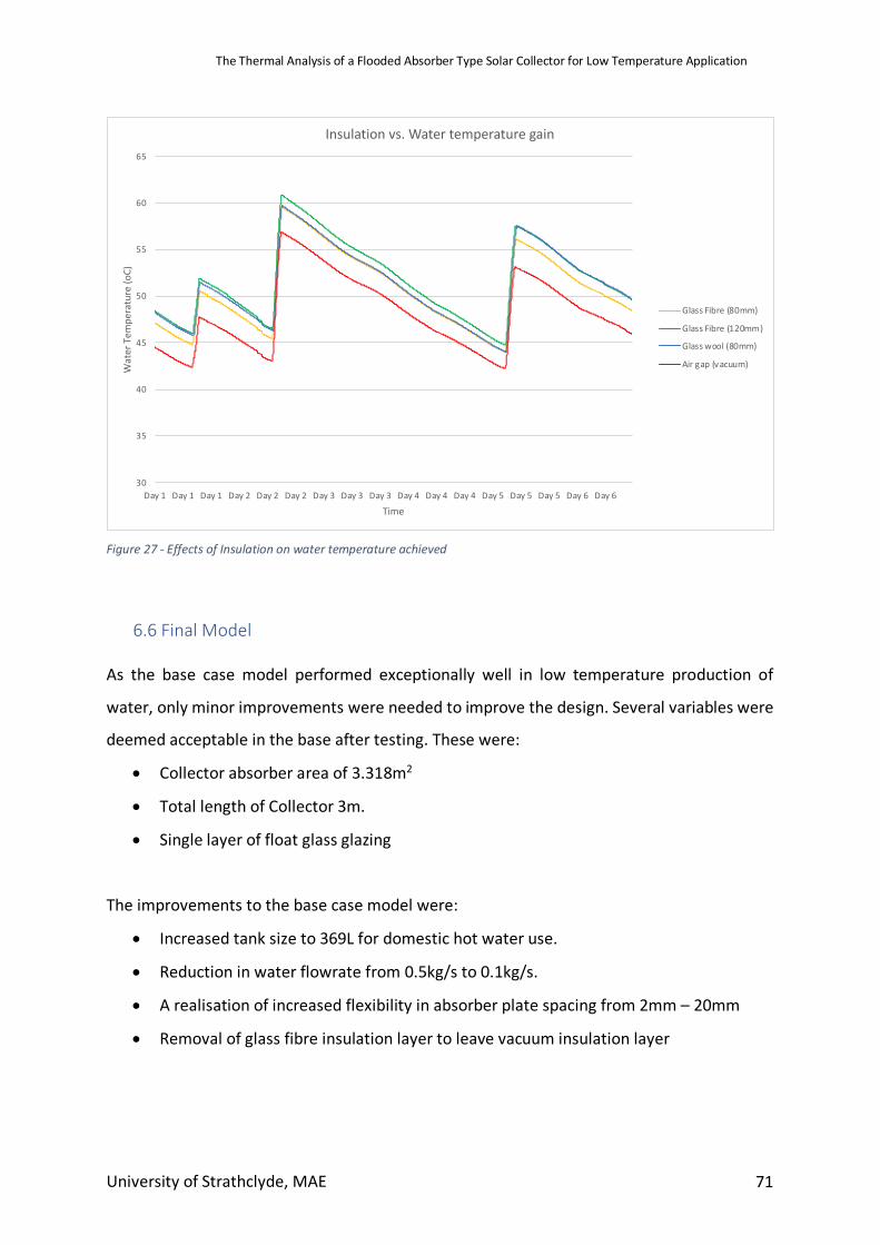
The Thermal Analysis of a Flooded Absorber Type Solar Collector for Low Temperature Application
University of Strathclyde, MAE 71
Figure 27 - Effects of Insulation on water temperature achieved
6.6 Final Model As the base case model performed exceptionally well in low temperature production of
water, only minor improvements were needed to improve the design. Several variables were
deemed acceptable in the base after testing. These were:
• Collector absorber area of 3.318m2
• Total length of Collector 3m.
• Single layer of float glass glazing
The improvements to the base case model were:
• Increased tank size to 369L for domestic hot water use.
• Reduction in water flowrate from 0.5kg/s to 0.1kg/s.
• A realisation of increased flexibility in absorber plate spacing from 2mm – 20mm
• Removal of glass fibre insulation layer to leave vacuum insulation layer
30
35
40
45
50
55
60
65
Day 1 Day 1 Day 1 Day 2 Day 2 Day 2 Day 3 Day 3 Day 3 Day 4 Day 4 Day 4 Day 5 Day 5 Day 5 Day 6 Day 6
Wat
er T
empe
ratu
re (o
C)
Time
Insulation vs. Water temperature gain
Glass Fibre (80mm)
Glass Fibre (120mm)
Glass wool (80mm)
Air gap (vacuum)
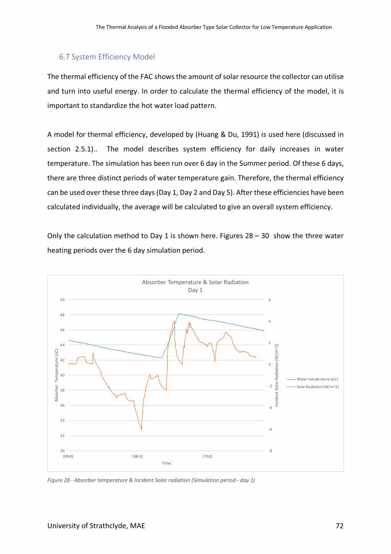
The Thermal Analysis of a Flooded Absorber Type Solar Collector for Low Temperature Application
University of Strathclyde, MAE 72
6.7 System Efficiency Model The thermal efficiency of the FAC shows the amount of solar resource the collector can utilise
and turn into useful energy. In order to calculate the thermal efficiency of the model, it is
important to standardize the hot water load pattern.
A model for thermal efficiency, developed by (Huang & Du, 1991) is used here (discussed in
section 2.5.1).. The model describes system efficiency for daily increases in water
temperature. The simulation has been run over 6 day in the Summer period. Of these 6 days,
there are three distinct periods of water temperature gain. Therefore, the thermal efficiency
can be used over these three days (Day 1, Day 2 and Day 5). After these efficiencies have been
calculated individually, the average will be calculated to give an overall system efficiency.
Only the calculation method to Day 1 is shown here. Figures 28 – 30 show the three water
heating periods over the 6 day simulation period.
Figure 28 - Absorber temperature & Incident Solar radiation (Simulation period - day 1)
-8
-6
-4
-2
0
2
4
6
30
32
34
36
38
40
42
44
46
48
50
00h01 08h31 17h01
Inci
dent
Sol
ar R
adia
tion
(W/m
^2)
Abso
rber
Tem
pera
ture
(oC)
Time
Absorber Temperature & Solar RadiationDay 1
Water temperature (oC)
Solar Radiation (W/m^2)
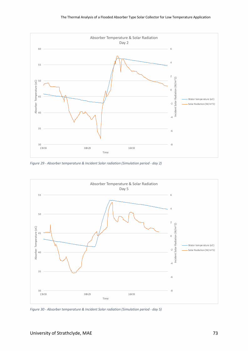
The Thermal Analysis of a Flooded Absorber Type Solar Collector for Low Temperature Application
University of Strathclyde, MAE 73
Figure 29 - Absorber temperature & Incident Solar radiation (Simulation period - day 2)
Figure 30 - Absorber temperature & Incident Solar radiation (Simulation period - day 5)
-8
-6
-4
-2
0
2
4
6
30
35
40
45
50
55
60
23h59 08h29 16h59
Inci
dent
Sol
ar R
adia
tion
(W/m
^2)
Abso
rber
Tem
pera
ture
(oC)
Time
Absorber Temperature & Solar RadiationDay 2
Water temperature (oC)
Solar Radiation (W/m^2)
-8
-6
-4
-2
0
2
4
6
30
35
40
45
50
55
23h59 08h29 16h59
Inci
dent
Sol
ar R
adia
tion
(W/m
^2)
Abso
rber
Tem
pera
ture
(oC)
Time
Absorber Temperature & Solar RadiationDay 5
Water temperature (oC)
Solar Radiation (W/m^2)
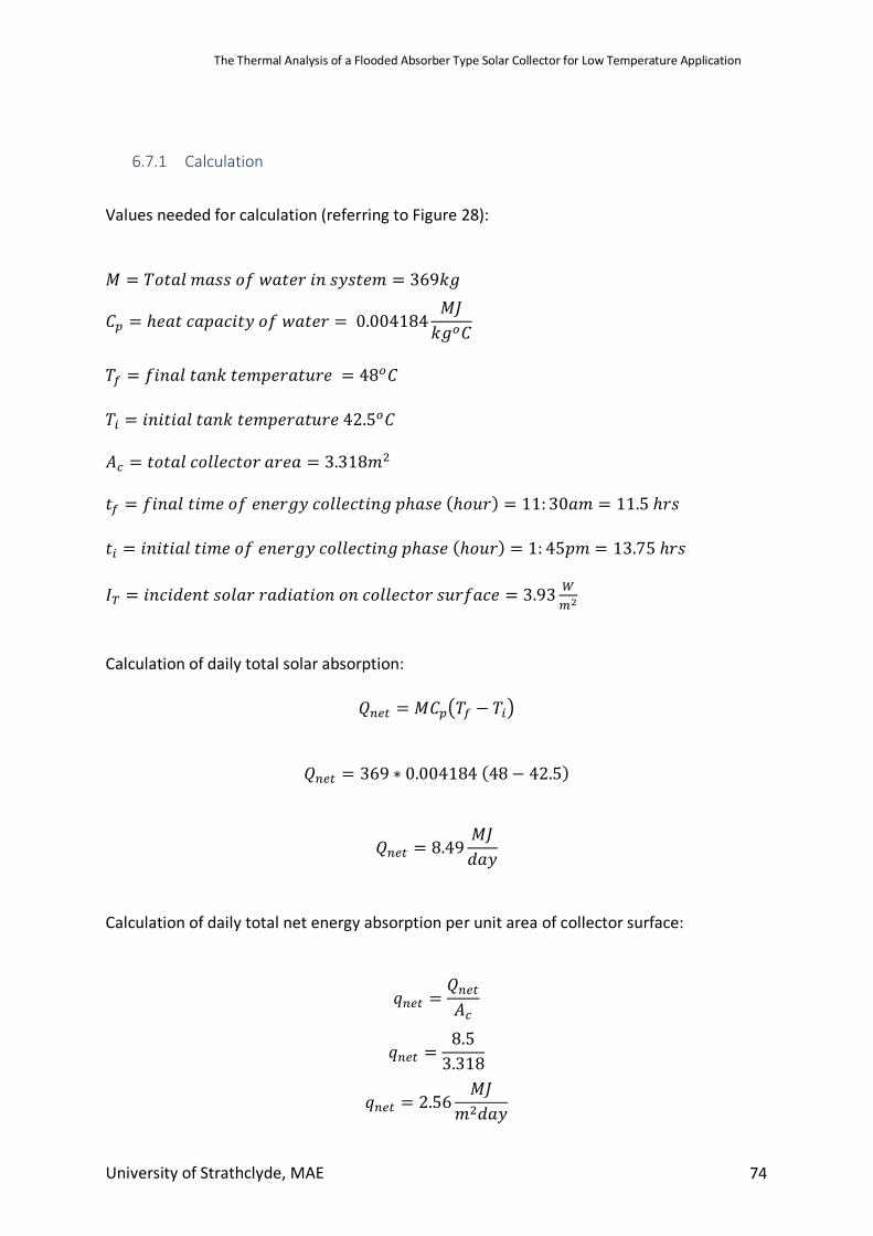
The Thermal Analysis of a Flooded Absorber Type Solar Collector for Low Temperature Application
University of Strathclyde, MAE 74
6.7.1 Calculation
Values needed for calculation (referring to Figure 28):
𝑀 = 𝑇𝑜𝑡𝑎𝑙𝑚𝑎𝑠𝑠𝑜𝑓𝑤𝑎𝑡𝑒𝑟𝑖𝑛𝑠𝑦𝑠𝑡𝑒𝑚 = 369𝑘𝑔
𝐶E = ℎ𝑒𝑎𝑡𝑐𝑎𝑝𝑎𝑐𝑖𝑡𝑦𝑜𝑓𝑤𝑎𝑡𝑒𝑟 = 0.004184𝑀𝐽𝑘𝑔;𝐶
𝑇I = 𝑓𝑖𝑛𝑎𝑙𝑡𝑎𝑛𝑘𝑡𝑒𝑚𝑝𝑒𝑟𝑎𝑡𝑢𝑟𝑒 = 48;𝐶 𝑇L = 𝑖𝑛𝑖𝑡𝑖𝑎𝑙𝑡𝑎𝑛𝑘𝑡𝑒𝑚𝑝𝑒𝑟𝑎𝑡𝑢𝑟𝑒42.5;𝐶 𝐴9 = 𝑡𝑜𝑡𝑎𝑙𝑐𝑜𝑙𝑙𝑒𝑐𝑡𝑜𝑟𝑎𝑟𝑒𝑎 = 3.318𝑚R 𝑡I = 𝑓𝑖𝑛𝑎𝑙𝑡𝑖𝑚𝑒𝑜𝑓𝑒𝑛𝑒𝑟𝑔𝑦𝑐𝑜𝑙𝑙𝑒𝑐𝑡𝑖𝑛𝑔𝑝ℎ𝑎𝑠𝑒(ℎ𝑜𝑢𝑟) = 11: 30𝑎𝑚 = 11.5ℎ𝑟𝑠 𝑡L = 𝑖𝑛𝑖𝑡𝑖𝑎𝑙𝑡𝑖𝑚𝑒𝑜𝑓𝑒𝑛𝑒𝑟𝑔𝑦𝑐𝑜𝑙𝑙𝑒𝑐𝑡𝑖𝑛𝑔𝑝ℎ𝑎𝑠𝑒(ℎ𝑜𝑢𝑟) = 1: 45𝑝𝑚 = 13.75ℎ𝑟𝑠 𝐼T = 𝑖𝑛𝑐𝑖𝑑𝑒𝑛𝑡𝑠𝑜𝑙𝑎𝑟𝑟𝑎𝑑𝑖𝑎𝑡𝑖𝑜𝑛𝑜𝑛𝑐𝑜𝑙𝑙𝑒𝑐𝑡𝑜𝑟𝑠𝑢𝑟𝑓𝑎𝑐𝑒 = 3.93 ~
o� Calculation of daily total solar absorption:
𝑄"#$ = 𝑀𝐶E`𝑇I − 𝑇La
𝑄"#$ = 369 ∗ 0.004184(48 − 42.5)
𝑄"#$ = 8.49𝑀𝐽𝑑𝑎𝑦
Calculation of daily total net energy absorption per unit area of collector surface:
𝑞"#$ =𝑄"#$𝐴9
𝑞"#$ =8.53.318
𝑞"#$ = 2.56𝑀𝐽
𝑚R𝑑𝑎𝑦
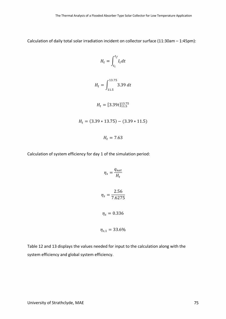
The Thermal Analysis of a Flooded Absorber Type Solar Collector for Low Temperature Application
University of Strathclyde, MAE 75
Calculation of daily total solar irradiation incident on collector surface (11:30am – 1:45pm):
𝐻$ = b 𝐼$𝑑𝑡$c
$d
𝐻$ = b 3.39𝑑𝑡��.��
��.�
𝐻$ = [3.39𝑡]��.���.��
𝐻$ = (3.39 ∗ 13.75) − (3.39 ∗ 11.5)
𝐻$ = 7.63
Calculation of system efficiency for day 1 of the simulation period:
𝜂< =𝑞"#$𝐻$
𝜂< =2.567.6275
𝜂< = 0.336
𝜂<,� = 33.6%
Table 12 and 13 displays the values needed for input to the calculation along with the
system efficiency and global system efficiency.
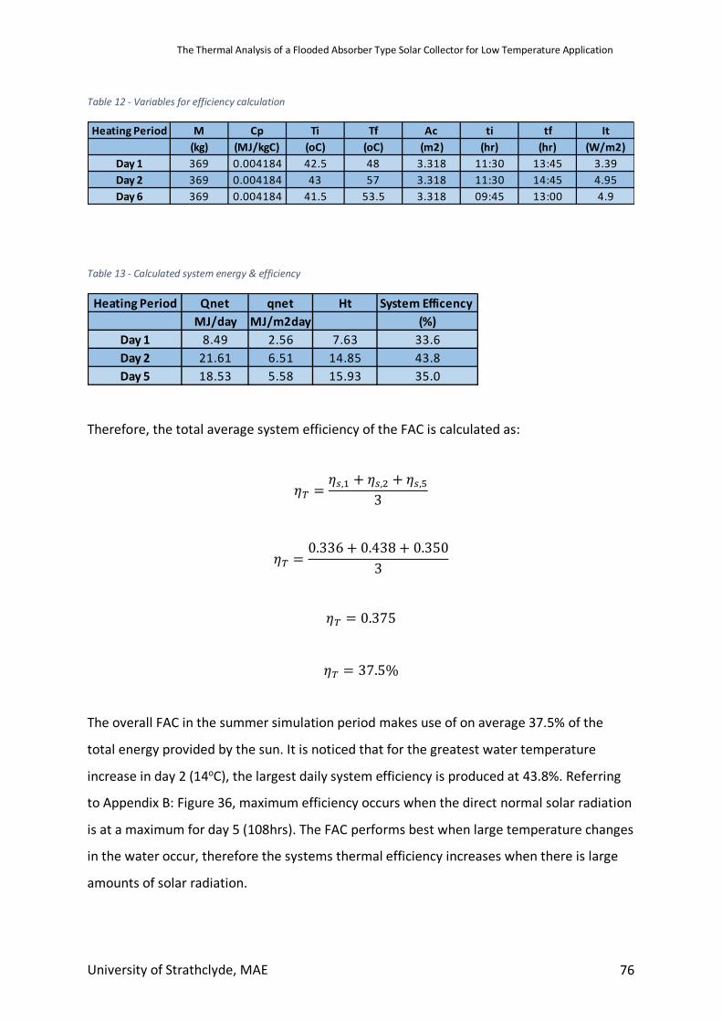
The Thermal Analysis of a Flooded Absorber Type Solar Collector for Low Temperature Application
University of Strathclyde, MAE 76
Table 12 - Variables for efficiency calculation
Table 13 - Calculated system energy & efficiency
Therefore, the total average system efficiency of the FAC is calculated as:
𝜂T =𝜂<,� + 𝜂<,R + 𝜂<,�
3
𝜂T =0.336 + 0.438 + 0.350
3
𝜂T = 0.375
𝜂T = 37.5%
The overall FAC in the summer simulation period makes use of on average 37.5% of the
total energy provided by the sun. It is noticed that for the greatest water temperature
increase in day 2 (14oC), the largest daily system efficiency is produced at 43.8%. Referring
to Appendix B: Figure 36, maximum efficiency occurs when the direct normal solar radiation
is at a maximum for day 5 (108hrs). The FAC performs best when large temperature changes
in the water occur, therefore the systems thermal efficiency increases when there is large
amounts of solar radiation.
Heating Period M Cp Ti Tf Ac ti tf It(kg) (MJ/kgC) (oC) (oC) (m2) (hr) (hr) (W/m2)
Day 1 369 0.004184 42.5 48 3.318 11:30 13:45 3.39Day 2 369 0.004184 43 57 3.318 11:30 14:45 4.95Day 6 369 0.004184 41.5 53.5 3.318 09:45 13:00 4.9
Heating Period Qnet qnet Ht System Efficency MJ/day MJ/m2day (%)
Day 1 8.49 2.56 7.63 33.6Day 2 21.61 6.51 14.85 43.8Day 5 18.53 5.58 15.93 35.0
The Thermal Analysis of a Flooded Absorber Type Solar Collector for Low Temperature Application
University of Strathclyde, MAE 77
7. Final Discussion A solar water heating system for low temperature application has been developed. The base
model designed performed very well in the Scottish summer environment, producing water
within the low temperature application bounds (40oC – 60oC) . However, the system could
not produce water temperatures in the Spring, Autumn and Winter months that was
satisfactory for low temperature bounds.
Temperature distribution though the typical parallel tube absorber configuration has been
noted as unsatisfactory although this problem is abated with the design of the FAC. Figure 17
shows that the temperature distributed over the absorber surface is uniform, aiding the
transfer of heat to the water. As a result of this, it is shown that the FAC design performs well
with a broad range of water flowrates, from 0.01kg/s up to 1kg/s (Figure 21 – 23). This is due
to the fact the water is always in complete contact with the absorber surface. Again, this
shows that water flowrate does not need to be a fixed value, aiding in the simplicity of
performance. A water tank of 369L was chosen in order to meet the demands of a typical
dwelling.
Design simplicity was a secondary aim of this project. The design of an FAC consists of simply
two absorber sheets which do not need to be welded in any place. After simulation, it was
also found that absorber spacing was not a strict variable therefore complex measurements
were not essential in design procedures. Figure 25 and 26 show that spacings from 2mm –
20mm obtain similar results, well within the bounds of low temperature application.
The effects of adding layers of glazing in the Summer simulation period showed that water
temperature gain was dramatically increased. Adding one layer of glazing produced a max
temperature of just under 100oC, while a third layer produced steam. As a temperature bound
of 40oC – 60oC was set, extra glazing was not required. However, in the interest of latent heat
systems, the FAC would perform well. This effect was reversed in the Winter months, as can
be seen in Figure 24, as the third layer of glazing reduced water temperature gain. This is
caused by the extra layer blocking out useful shortwave radiation to the absorber. In winter,
The Thermal Analysis of a Flooded Absorber Type Solar Collector for Low Temperature Application
University of Strathclyde, MAE 78
the collector relies on shortwave radiation for temperature gain as the ambient temperature
is much lower.
The glazing material was also chosen to be float glass. Float glass is used in a broader range
of applications compared to commonly used low iron glass. This means that it is far more
likely to be available in less developed areas.
The tilt angle of the FAC was kept horizontal. After reviewing the literature, it is found the
values of optimum tilt are disparate. However, in Summer months, collector tilt is relatively
close to horizontal. The optimum tilt completely depends on the location the collector is set
up in. Achieving appropriate water temperatures with a 0o tilt means that azimuth angle also
becomes irrelevant. This means the collector can be deployed with little knowledge of angles
and orientation, aiding to the simplicity.
Within the construction of the collector, it was also found that removing the layer of glass
fibre had a very small effect on water temperature gain (Figure 27). Using an air gap instead
of insulation material only reduced the temperature of water obtained by a few degrees. The
lowest temperature achieved was still above the lower bound of 40oC. Removing the need for
specific insulation materials again meets the secondary aim of simple design.
The FAC design was simulated in a Scottish climate to test the performance is a low solar
radiation environment. It was assumed that if the collector could perform well in a Scottish
environment, it would be absolutely applicable in a solar rich climate. If the FAC was simulated
in a solar rich environment, it could not be concluded that it could work in a less solar rich
environment.
Even with the simplicity of design, thermal efficiency of the FAC still reached an average of
37.5%, in low solar conditions (Glasgow). As the design was aimed at meeting low
temperature requirements and ideally being simple, high efficiency was not expected or
nessesary. However, it was found that when temperature gain of water was large, system
efficiency increased. For a temperature gain of 5.5oC, a system efficiency was calculated as
The Thermal Analysis of a Flooded Absorber Type Solar Collector for Low Temperature Application
University of Strathclyde, MAE 79
33.6%. When water temperature gain rose to 14oC, an efficiency 43.8% was obtained. In light
of this, the FAC could be very efficient for high water temperature gain. However, in order to
get a better understanding of overall system efficiency, a larger simulation period would need
to be completed.
The main findings of the FAC compared to the FPC design were as follows:
• The FAC can handle high flowrates compared to FPC. This is due to the fact the
absorber is in constant contact with the fluid instead of just being in pipes.
• Simple design
o No insulation material required for low temperature application
o Can be laid flat, no complex procedure to ensure collector tilt
o Flexibility of spacing of absorber plates up to 20mm.
8. Conclusion To sum up the major components of the final model developed:
• Collector absorber area of 3.318m2
• Total length of Collector 3m.
• Single layer of float glass glazing
• Tank size to 369L for domestic hot water use.
• Water flowrate: 0.1kg/s.
• Absorber spacing between 2mm – 20mm
• Vacuum insulation layer
The main design objectives have been met by the designed FAC. Water is produced between
temperatures of 40 – 60oC which was the initial aim of the system. Then through testing in
ESP-r simulation environment, the base design was proven to work well with only minor
adjustments needed. A system overall efficiency of 37.5% was found which is lower than
standard solar thermal collectors. However, system design was proven to be simple and
therefore has the possibility of being widely deployable.
The Thermal Analysis of a Flooded Absorber Type Solar Collector for Low Temperature Application
University of Strathclyde, MAE 80
9. Future Work The areas in which the work completed in this thesis could be furthered are as follows:
• To obtain a more accurate understanding of system efficiency, the FAC should be
simulated and tested under standard EN-12975. The EN-12975 provides the
European standard for performance testing of solar collectors. This would give a
realistic efficiency value that could be truly compared to other solar collector
designs.
• To compare the FAC with the parallel tube configuration FPC, a parallel tube FPC
collector should be modelled in ESP-r. This could be done by changing the absorber
geometry to pipes by cutting each thermal zone into thin strips and applying a pipe
flow component link.
• To increase the accuracy of the simulation of the FAC in ESP-r, more zones could be
created in order to have a smoother increase in temperature as the water flows
from zone to zone.
• After adding extra layers of glazing, it was found the FAC would likely perform well
even in the Spring season. The system could possibly be designed to produce water
for low temperature application through the Summer and through the Spring.
• The price of the FAC system developed was not in the scope of this research. If a
system price were generated, it could be used to assess the economic feasibility of
the design to be deployed in LEDC’s.
• Asses the possibility of the FAC design working under a thermosiphon principle. The
addition of the pump means the system needs external energy in order to operate.
Working under the thermosiphon principle would mean the FAC could operate
anywhere, without external power requirement.
10. References Al-Beaini, S., Benhabib, M., Engelage, S., & Langton, A. (2007). Domestic Solar Water Heater
for Developing Countries. Retrieved from http://www.solaripedia.com/files/587.pdf Al-Rawahi, N. Z., Zurigat, Y. H., & Al-Azri, N. A. (2011). Prediction of Hourly Solar Radiation
on Horizontal and Inclined Surfaces for Muscat/Oman. The Journal of Engineering Research [TJER], 8(2), 19. https://doi.org/10.24200/tjer.vol8iss2pp19-31
The Thermal Analysis of a Flooded Absorber Type Solar Collector for Low Temperature Application
University of Strathclyde, MAE 81
Amrutkar, S. K., Ghodke, S., & Patil, K. N. (2012). Solar Flat Plate Collector Analysis, 2, 207–213. Retrieved from www.iosrjen.org
Ayoub, J., & Alward, R. (1996). Water requirements and remote arid areas: the need for small-scale desalination. DESALINATION ELSEVIER Desalination (Vol. 107). Retrieved from https://ac.els-cdn.com/S0011916496001580/1-s2.0-S0011916496001580-main.pdf?_tid=f0340984-3d0e-4aa2-acac-f9bb24def740&acdnat=1532531992_62e0a0463cccccbd7f6c1291e144bc20
Bakari, R., Minja, R. J. A., & Njau, K. N. (2014). Effect of Glass Thickness on Performance of Flat Plate Solar Collectors for Fruits Drying. Journal of Energy, 2014, 1–8. https://doi.org/10.1155/2014/247287
Beikircher, T., Berger, V., Osgyan, P., Reuß, M., & Streib, G. (2014). Low-e confined air chambers in solar flat-plate collectors as an economic new type of rear side insulation avoiding moisture problems. Solar Energy, 105, 280–289. https://doi.org/10.1016/J.SOLENER.2014.03.033
Beikircher, T., Möckl, M., Osgyan, P., & Streib, G. (2015). Advanced solar flat plate collectors with full area absorber, front side film and rear side vacuum super insulation. Solar Energy Materials and Solar Cells, 141, 398–406. https://doi.org/10.1016/J.SOLMAT.2015.06.019
Blaga, A. (1978). Use of plastics in solar energy applications. Solar Energy, 21(4), 331–338. https://doi.org/10.1016/0038-092X(78)90010-5
California Solar Center. (2015). Solar Thermal History. Retrieved July 23, 2018, from http://californiasolarcenter.org/history-solarthermal/
Chang, T. P. (2008). Study on the Optimal Tilt Angle of Solar Collector According to Different Radiation Types. International Journal of Applied Science and Engineering, 6, 151. Retrieved from https://www.cyut.edu.tw/~ijase/2008/2008/014011-6.pdf
Chen, X., Liu, L., Yu, P. Y., & Mao, S. S. (2011). Increasing solar absorption for photocatalysis with black hydrogenated titanium dioxide nanocrystals. Science (New York, N.Y.), 331(6018), 746–50. https://doi.org/10.1126/science.1200448
Chen, Z., Furbo, S., Perers, B., Fan, J., & Andersen, E. (2012). Efficiencies of Flat Plate Solar Collectors at Different Flow Rates. Energy Procedia, 30, 65–72. https://doi.org/10.1016/j.egypro.2012.11.009
Chong, K. K., Chay, K. G., & Chin, K. H. (2012). Study of a solar water heater using stationary V-trough collector. Renewable Energy, 39, 207–215. https://doi.org/10.1016/j.renene.2011.08.002
DEFRA. (2013). At Home with Water - Great Britain. Retrieved from http://www.energysavingtrust.org.uk/sites/default/files/reports/AtHomewithWater%287%29.pdf
Drosou, V. N., Tsekouras, P. D., Oikonomou, T. I., Kosmopoulos, P. I., & Karytsas, C. S. (2013). The HIGH-COMBI project: High solar fraction heating and cooling systems with combination of innovative components and methods. Renewable and Sustainable Energy Reviews, 29, 463–472. https://doi.org/10.1016/j.rser.2013.08.019
Eke, A. Ben. (2011). Prediction of optimum angle of inclination for flat plate solar collector in Zaria, Nigeria. Agricultural Engineering International: CIGR Journal, 13(4).
El-Sherbiny, S. M., Hollands, K. G. T., & Raithby, G. D. (1978). Free Convection across Inclined Air Layers with One Surface V-Corrugated. Journal of Heat Transfer, 100(3), 410. https://doi.org/10.1115/1.3450823
Elminir, H. K., Ghitas, A. E., El-Hussainy, F., Hamid, R., Beheary, M. M., & Abdel-Moneim, K.
The Thermal Analysis of a Flooded Absorber Type Solar Collector for Low Temperature Application
University of Strathclyde, MAE 82
M. (2006). Optimum solar flat-plate collector slope: Case study for Helwan, Egypt. Energy Conversion and Management, 47(5), 624–637. https://doi.org/10.1016/J.ENCONMAN.2005.05.015
Energy Saving Trust. (2018). Heating and Hot Water | Energy Saving Trust. Retrieved August 24, 2018, from http://www.energysavingtrust.org.uk/home-energy-efficiency/heating-and-hot-water
ESRU. (n.d.). ESP-r. Retrieved July 9, 2018, from http://www.esru.strath.ac.uk/Programs/ESP-r.htm
Firebird. (2011). Guide to Solar Thermal Systems. Retrieved from https://firebird.uk.com/wp-content/uploads/2016/06/Guide-to-Solar-Thermal-Systems-Brochure-2012.pdf
Gammon, R. B. (1978). THE MEASUREMENT OF OPTICAL PROPERTIES OF SELECTIVE SURFACES USING A SOLAR CALORIMETER. Solar Energy, 21, 193–199. Retrieved from https://ac.els-cdn.com/0038092X7890021X/1-s2.0-0038092X7890021X-main.pdf?_tid=79c05524-5041-49f5-84ba-e7ea488c5fb5&acdnat=1532006815_32b7b30afd43bb6a69a429fbbb4d9ed4
Gunjo, D. G., Mahanta, P., & Robi, P. S. (2017). CFD and experimental investigation of flat plate solar water heating system under steady state condition. Renewable Energy, 106, 24–36. https://doi.org/10.1016/J.RENENE.2016.12.041
Hirasawa, S., Tsubota, R., Kawanami, T., & Shirai, K. (2013). Reduction of heat loss from solar thermal collector by diminishing natural convection with high-porosity porous medium. Solar Energy, 97, 305–313. https://doi.org/10.1016/j.solener.2013.08.035
Hobbi, A., & Siddiqui, K. (2009). Experimental study on the effect of heat transfer enhancement devices in flat-plate solar collectors. International Journal of Heat and Mass Transfer, 52(19–20), 4650–4658. https://doi.org/10.1016/J.IJHEATMASSTRANSFER.2009.03.018
Huang, B. J., & Du, S. C. (1991). A Performance Test Method of Solar Thermosyphon Systems. Journal of Solar Energy Engineering, 113(3), 172. https://doi.org/10.1115/1.2930489
Jamar, A., Majid, Z. A. A., Azmi, W. H., Norhafana, M., & Razak, A. A. (2016). A review of water heating system for solar energy applications ☆. https://doi.org/10.1016/j.icheatmasstransfer.2016.05.028
Jeena, J., & Nidhi, M. J. (2015). A Review on Performance of Solar Thermal Flat Plate Collector Using Different Heat Transfer Fluids, 2(7), 204–210. Retrieved from http://troindia.in/journal/ijcesr/vol2iss7/204-210.pdf
Joseph, J., Saravanan, R., & Renganarayanan, S. (2005). Studies on a single-stage solar desalination system for domestic applications. Retrieved from www.elsevier.com/locate/desal
Jouybari, H. J., Saedodin, S., Zamzamian, A., Nimvari, M. E., & Wongwises, S. (2017). Effects of porous material and nanoparticles on the thermal performance of a flat plate solar collector: An experimental study. Renewable Energy, 114, 1407–1418. https://doi.org/10.1016/j.renene.2017.07.008
Kalidasan, B., & Srinivas, T. (2014). Study on Effect of Number of Transparent Covers and Refractive Index on Performance of Solar Water Heater. Journal of Renewable Energy, 2014, 1–11. https://doi.org/10.1155/2014/757618
Kalogirou, S. (2005). Seawater desalination using renewable energy sources. Progress in Energy and Combustion Science, 31(3), 242–281.
The Thermal Analysis of a Flooded Absorber Type Solar Collector for Low Temperature Application
University of Strathclyde, MAE 83
https://doi.org/10.1016/j.pecs.2005.03.001 Kalogirou, S. (2014). Solar Energy Engineering: Processes and Systems. Kalogirou, S. A. (2004). Solar thermal collectors and applications. Progress in Energy and
Combustion Science, 30(3), 231–295. https://doi.org/10.1016/j.pecs.2004.02.001 Kalogirou, S. A. (2009). Solar Energy Engineering. Elsevier. https://doi.org/10.1016/B978-0-
12-374501-9.X0001-5 Karagiorgas, M., Botzios, A., & Tsoutsos, T. (2001). Industrial solar thermal applications in
Greece Economic evaluation, quality requirements and case studies. Renewable and Sustainable Energy Reviews, 5, 157–173. Retrieved from www.elsevier.com/locate/rser
Karim, M. R., Nakoa, K. M. ., Mahmood, S. L., & Akhanda, D. M. A. R. (2012). International journal of renewable energy research. International Journal of Renewable Energy Research (IJRER) (Vol. 1). Gazi Univ., Fac. of Technology, Dep. of Electrical et Electronics Eng. Retrieved from http://ijrer.com/index.php/ijrer/article/view/69
Kemp, C. M. (1891, April 28). Apparatus for utilizing the sun s rays for heating water. Retrieved from https://patents.google.com/patent/US451384A/en
Keshavarz, S. A., Talebizadeh, P., Adalati, S., Mehrabian, M. A., & Abdolzadeh, M. (2012). International journal of renewable energy research. International Journal of Renewable Energy Research (IJRER) (Vol. 2). Gazi Univ., Fac. of Technology, Dep. of Electrical et Electronics Eng. Retrieved from http://ijrer.com/index.php/ijrer/article/view/367
Khanna+, M. L. (1968). The Development of a Solar Water Heater and its Field Trials under Indian Tropical Conditions*, 255–261. Retrieved from https://ac.els-cdn.com/0038092X6890011X/1-s2.0-0038092X6890011X-main.pdf?_tid=53f41a28-a804-44fd-9c37-d15074c83d85&acdnat=1531911320_9ba0305c6e2dbb9f7f12e2d856f70839
Köhl, M. (2012). Polymeric Materials for Solar Thermal Applications. Retrieved from http://dnb.d-nb.de.
Kumar Verma, S., Kumar Tiwari, A., & Singh Chauhan, D. (2017). Experimental evaluation of flat plate solar collector using nanofluids. https://doi.org/10.1016/j.enconman.2016.12.037
Lampert, C. M. (1979). Coatings for enhanced photothermal energy collection II. Non-selective and energy control films. Solar Energy Materials, 2(1), 1–17. https://doi.org/10.1016/0165-1633(79)90026-1
Lenel, U. R. (1984). A REVIEW OF MATERIALS FOR SOLAR HEATING SYSTEMS FOR DOMESTIC HOT WATER (Vol. 32). Retrieved from https://ac.els-cdn.com/0038092X84900549/1-s2.0-0038092X84900549-main.pdf?_tid=825202a5-cc78-4e29-aa57-b19f47a58112&acdnat=1534025657_dc42190d37629266a01fe186c06e63c1
Madhukeshwara, N., & Prakash, E. S. (2012). An investigation on the performance characteristics of solar flat plate collector with different selective surface coatings. Journal Homepage: Www.IJEE.IEEFoundation.Org ISSN, 3(1), 2076–2909. Retrieved from www.IJEE.IEEFoundation.org
Mauthner, F., Weiss, W., & Spörk-Dür, M. (2014). Solar Heat Worldwide Markets and Contribution to the Energy Supply 2014. IEA Solar Heating & Cooling Programme. Retrieved from https://www.iea-shc.org/data/sites/1/publications/Solar-Heat-Worldwide-2016.pdf
Meibodi, S. S., Kianifar, A., Niazmand, H., Mahian, O., & Wongwises, S. (2015). Experimental investigation on the thermal efficiency and performance characteristics of a flat plate solar collector using SiO 2 /EG-water nanofluids ☆. International Communications in
The Thermal Analysis of a Flooded Absorber Type Solar Collector for Low Temperature Application
University of Strathclyde, MAE 84
Heat and Mass Transfer, 65, 71–75. https://doi.org/10.1016/j.icheatmasstransfer.2015.02.011
Michaelides, I. M., & Eleftheriou, P. C. (2011). An experimental investigation of the performance boundaries of a solar water heating system. Experimental Thermal and Fluid Science, 35(6), 1002–1009. https://doi.org/10.1016/J.EXPTHERMFLUSCI.2011.02.001
Monterrey, T. De. (2008). Vaccum Chamber Solar Collector Development using Triz. Solar Energy, 2–10. Retrieved from https://www.aitriz.org/articles/TRIZFeatures/30383131-526F76697261.pdf
Mordor Intelligence. (2017). Non Concentrating Solar Collectors Market | Industry Analysis | Outlook 2022. Retrieved from https://www.mordorintelligence.com/industry-reports/global-non-concentrating-type-solar-collector-market-industry
Moss, R. W., Shire, G. S. F., Henshall, P., Eames, P. C., Arya, F., & Hyde, T. (2017). Optimal passage size for solar collector microchannel and tube-on-plate absorbers. Solar Energy, 153, 718–731. https://doi.org/10.1016/j.solener.2017.05.030
Nikogosian, A. (2017). FLAT PLATE SOLAR WATER HEATERS WORKING ON THERMOSYPHON PRINCIPLE IN HOT CLIMATES: CFD INVESTIGATION OF NATURAL CONVECTION FLOW. University of Strathclyde.
Nnamchi, S. N. (2012). Optimum Collector Tilt Angles For Low Latitudes. The Open Renewable Energy Journal (Vol. 5). Retrieved from https://pdfs.semanticscholar.org/2b55/41a77494fe08ec545cebf3c2ff46200e20c0.pdf
NRC. (n.d.). Natural Resources Canada | Natural Resources Canada. Retrieved July 20, 2018, from https://www.nrcan.gc.ca/home
Pandey, K. M., & Chaurasiya, R. (2016). A review on analysis and development of solar flat plate collector. Renewable and Sustainable Energy Reviews, 67, 641–650. https://doi.org/10.1016/j.rser.2016.09.078
Patel, K., Pragna Patel, M., & Patel, M. J. (2012). REVIEW OF SOLAR WATER HEATING SYSTEMS. International Journal of Advanced Engineering Technology. Retrieved from http://www.technicaljournalsonline.com/ijeat/VOL III/IJAET VOL III ISSUE IV OCTBER DECEMBER 2012/Article 34 Vol III issue IV 2012.pdf
Raisul Islam, M., Sumathy, K., & Ullah Khan, S. (2013). Solar water heating systems and their market trends. Renewable and Sustainable Energy Reviews, 17, 1–25. https://doi.org/10.1016/J.RSER.2012.09.011
Rommel, M., Köhl, M., Graf, W., Wellens, C., Brucker, F., Lustig, K., & Bahr, P. (1997). Corrosion-free collectors with selectively coated plastic absorbers. Desalination, 109(2), 149–155. https://doi.org/10.1016/S0011-9164(97)00060-X
Russell, L. D. (2015). All-polymer Flate Plate Heating Solar Panel With Integrated Controller. Retrieved from https://patentimages.storage.googleapis.com/b6/76/e5/8b1fa3521c717d/US20150377515A1.pdf
Schwarzer, K., Vieira, M. E., Müller, C., Lehmann, H., & Coutinho, L. (2003). MODULAR SOLAR THERMAL DESALINATION SYSTEM WITH FLAT PLATE COLLECTOR. Retrieved from http://www.rio12.com/rio3/proceedings/RIO3_281_K_Schwarzer.pdf
Scott, J. E. (1976). THE SOLAR WATER HEATER INDUSTRY IN SOUTH FLORIDA: HISTORY AND PROJECTIONS. Solar Energy, 18, 387–393. Retrieved from https://ac.els-cdn.com/0038092X76900037/1-s2.0-0038092X76900037-main.pdf?_tid=70c49e48-a523-4a32-b983-
The Thermal Analysis of a Flooded Absorber Type Solar Collector for Low Temperature Application
University of Strathclyde, MAE 85
cf9f0273cdf0&acdnat=1532369462_cad00b6138eabbc7ba4e14221070fe1c Sengar, S. H. (2004). Design and Development of Composite Solar Appliances for Domestic
Use. Retrieved from http://krishikosh.egranth.ac.in/handle/1/5810019930 Singh, P. L., Sarviya, R. M., & Bhagoria, J. L. (2010). Heat loss study of trapezoidal cavity
absorbers for linear solar concentrating collector. Energy Conversion and Management, 51(2), 329–337. https://doi.org/10.1016/J.ENCONMAN.2009.09.029
Sö zen, A., & Menlik, T. (2008). Determination of efficiency of flat-plate solar collectors using neural network approach. https://doi.org/10.1016/j.eswa.2007.08.080
Solar Energy. (2015). Low temperature thermal solar energy. Retrieved August 24, 2018, from https://solar-energy.technology/solar-thermal/low-temperature
Streicher, W. (2016). Solar thermal technologies for domestic hot water preparation and space heating. Renewable Heating and Cooling, 9–39. https://doi.org/10.1016/B978-1-78242-213-6.00002-3
TheGreenAge. (2018). Evacuated Tube Solar Thermal Hot Water Systems. Retrieved July 19, 2018, from https://www.thegreenage.co.uk/article/how-do-evacuated-tube-solar-thermal-hot-water-systems-work/
U.S Department of Energy. (2002). The History of Solar. Retrieved from http://solarcooking.org/saussure.htm
Ulgen, K. (2006). Optimum Tilt Angle for Solar Collectors. Energy Sources, Part A: Recovery, Utilization, and Environmental Effects, 28(13), 1171–1180. https://doi.org/10.1080/00908310600584524
Van Niekerk, W. M. K., du Toit, C. G., & Scheffler, T. B. (1996). Performance modelling of a parallel tube polymer absorber. Solar Energy, 58(1–3), 39–44. https://doi.org/10.1016/0038-092X(96)00052-7
Wessley, G. J. J., & Mathews, P. K. (2014). Experimental Analysis of a Flat Plate Solar Collector System for Small-Scale Desalination Applications. Advanced Materials Research, 984–985, 800–806. https://doi.org/10.4028/www.scientific.net/AMR.984-985.800
Yeh, H.-M., & Chen, L.-C. (1985). A Study on Thermosyphon Solar Water Heater With Parallel Flat-Plate Collector. Retrieved from https://ac.els-cdn.com/0360544286901064/1-s2.0-0360544286901064-main.pdf?_tid=0dde640a-d681-419c-a7a5-22f8c68aed8d&acdnat=1531928027_1d51db7c7074a6addd16431c607dd9d8
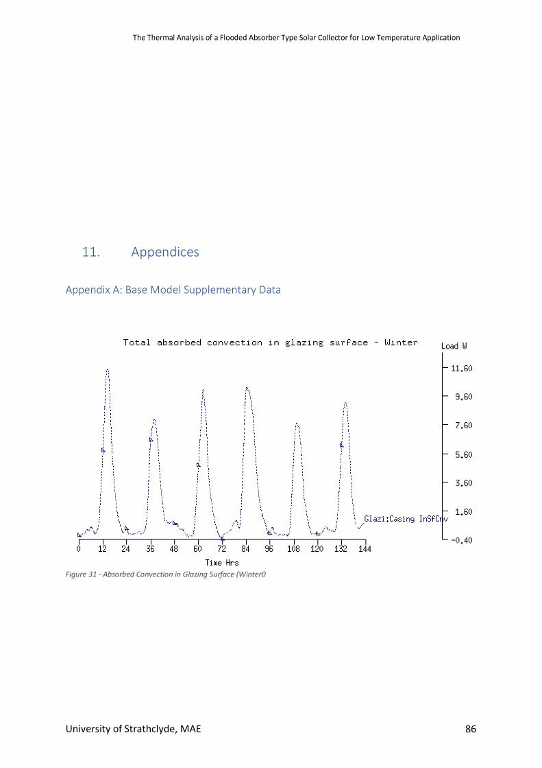
The Thermal Analysis of a Flooded Absorber Type Solar Collector for Low Temperature Application
University of Strathclyde, MAE 86
11. Appendices
Appendix A: Base Model Supplementary Data
Figure 31 - Absorbed Convection in Glazing Surface (Winter0
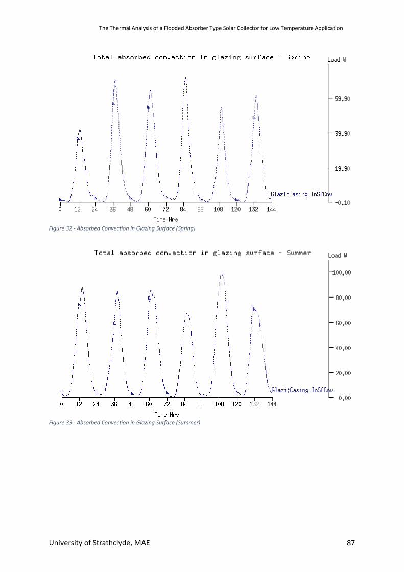
The Thermal Analysis of a Flooded Absorber Type Solar Collector for Low Temperature Application
University of Strathclyde, MAE 87
Figure 32 - Absorbed Convection in Glazing Surface (Spring)
Figure 33 - Absorbed Convection in Glazing Surface (Summer)
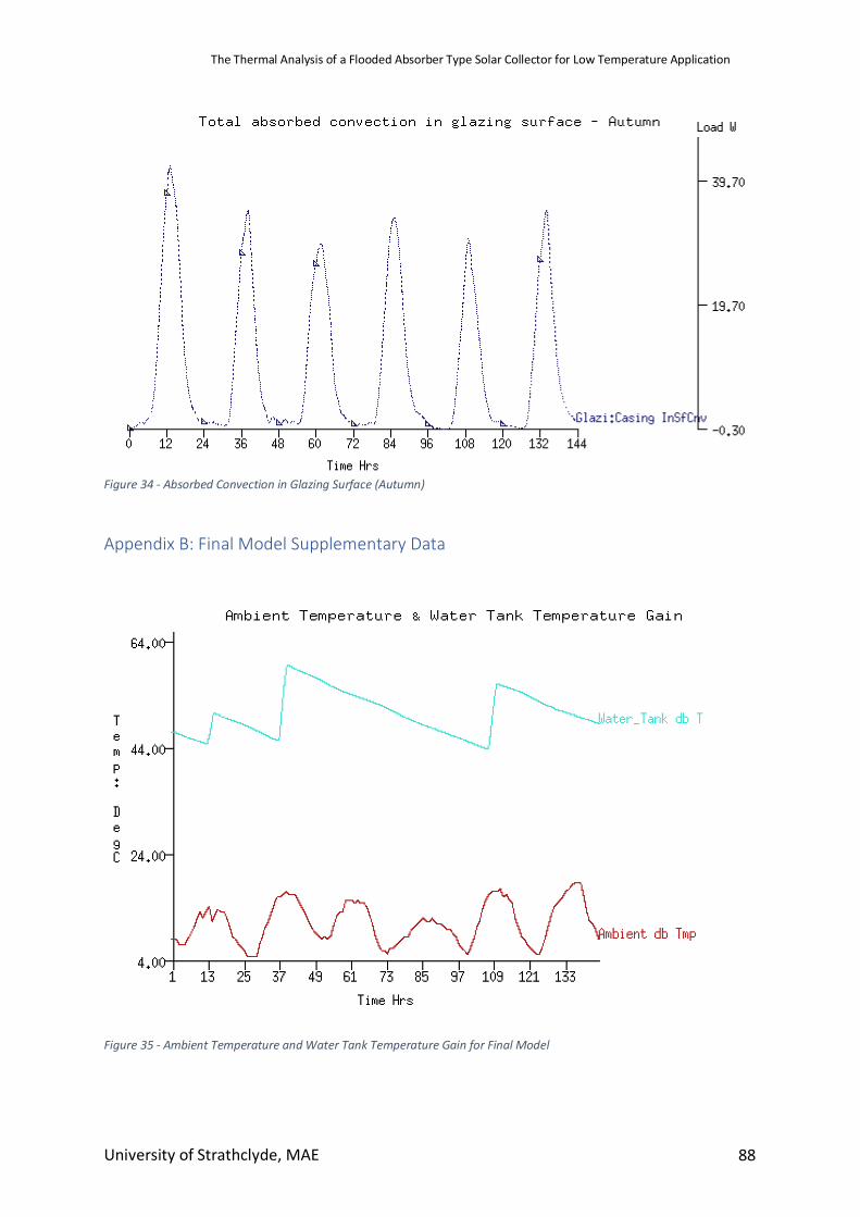
The Thermal Analysis of a Flooded Absorber Type Solar Collector for Low Temperature Application
University of Strathclyde, MAE 88
Figure 34 - Absorbed Convection in Glazing Surface (Autumn)
Appendix B: Final Model Supplementary Data
Figure 35 - Ambient Temperature and Water Tank Temperature Gain for Final Model
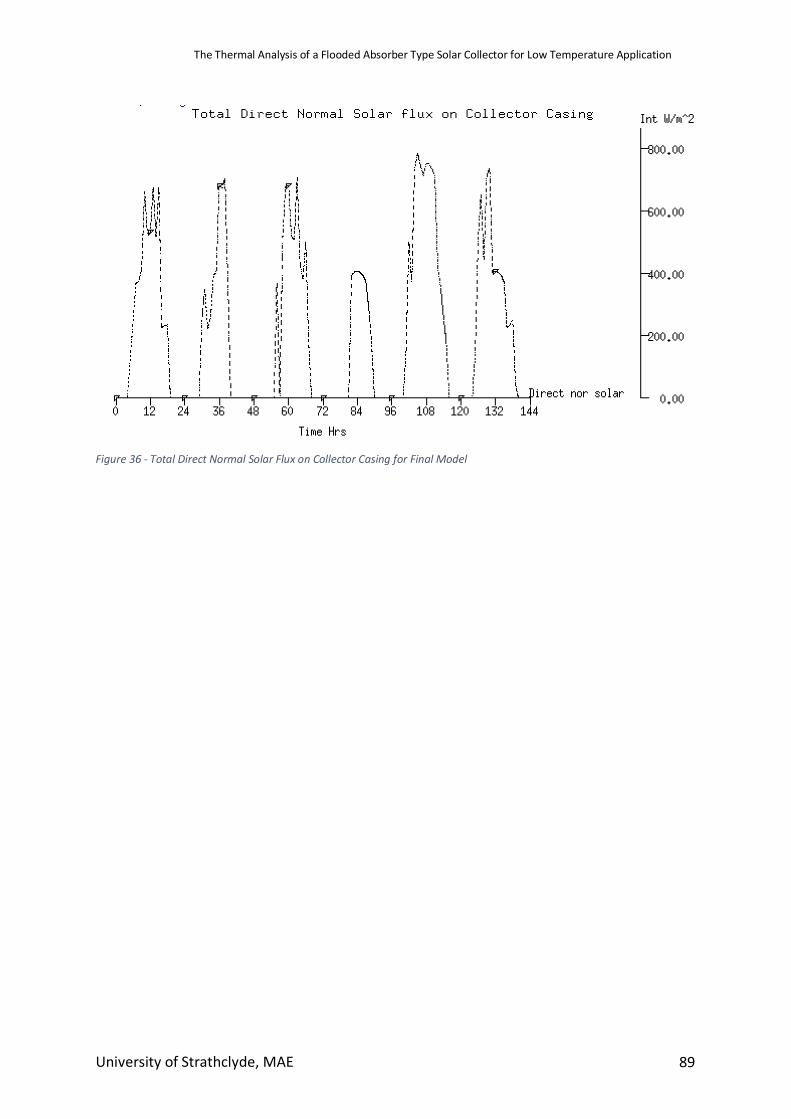
The Thermal Analysis of a Flooded Absorber Type Solar Collector for Low Temperature Application
University of Strathclyde, MAE 89
Figure 36 - Total Direct Normal Solar Flux on Collector Casing for Final Model