Embed Size (px)
Citation preview

1
The Terregator Mobile RobotLee Champeny-Bares, Syd Coppersmith and Kevin Dowling
CMU-RI-TR-93-03
Field Robotics Center
The Robotics Institute
Carnegie Mellon University
Pittsburgh, Pennsylvania 15213
May 1991
Copyright 1991 Carnegie Mellon University
This research was sponsored by The Robotics Institute. Later research efforts using theTerregator were sponsored by the US Bureau of Mines, DARPA and the EPA. Views are
those of the authors and should not be interpreted as representing the official policies,either expressed or implied, of the funding agencies.

2
1. Introduction 7
2. Terregator Project Summary 9
3. Vehicle Design Specification 113.1 Vehicle Objectives 11
3.2 Design and Production Constraints 13
3.2.1 Design Constraints 14
3.2.2 Production Constraints 14
3.3 Design Specifications 14
4. Terregator Vehicle Description 174.1 Introduction 17
4.2 General Configuration 17
4.3 Locomotor 19
4.3.1 Base Frame 20
4.3.2 Motors and Drive Train 21
4.3.3 Roll Frame 25
4.3.4 Rack Mount Enclosure 26
4.4 On-Board Control System 28
4.4.1 Joystick Controller 31
4.5 Remote Console 32
4.6 Telemetry System 32
4.6.1 Radio Serial RS-232 Link 32
4.6.2 Microwave Video Link 32
4.7 Orientation Sensors 32
4.8 Power Supply System 33
4.8.1 Generation 33
4.8.2 Distribution Power 35
4.8.3 Protection 35
5. Evaluation and Conclusions 365.1 Evaluations 36
5.2 Experiments 36
5.3 Conclusion 38

3
A. Weight and Power Budgets 39A.1 Itemized Vehicle Weight 39
A.2 Itemized Power Budget 40
B. Bibliography 41B.1 Personnel Acknowledgments 41
C. Addendum 1991 43
D. Recent Terregator Research 45

4
1. List of Figures
Figure 1-1 Terregator with camera and telemetry navigating on CMU sidewalks. 8
Figure 4-1 Terregator 18
Figure 4-2 Mechanical layout of the Terregator 20
Figure 4-3 Terregator base frame and interior components. 22
Figure 4-4 Axle Assembly 23
Figure 4-5 Electrical layout for the Terregator 24
Figure 4-6 Base frame mechanical layout and cabling layout 26
Figure 4-7 Terregator command and control signals 30
Figure 4-8 Power Generator 34
Figure 5-1 Terregator with laser scanner navigating in a coal mine. 37

5

6
AbstractThe Terrestrial Navigator, or Terregator, is a mobile robot device designed to provide areliable and rugged testbed for both indoor and outdoor work in robotic navigation,guidance, sensor interpretation, and architectures. The design of mobile robot involvesconflicting needs and a wide mix of disciplines. The Terregator design resolves many suchneeds through flexible and extensible mechanics, electronics, hardware and software. It is asix-wheeled skid-steer machine utilizing compliant tires for suspension, a hybrid powersystem provides for different modes and environments during operation and a rugged drivesystem and integral controller provide a complete package for doing robotics research.

7
1. Introduction
The Terregator (Terrestrial Navigator) is a driverless outdoor vehicle developed forautonomous navigation research. Application areas for autonomous vehicle technologyinclude undersea exploration, transportation, hazardous waste mapping, material handling,and exploration of planetary surfaces.
Terregator subsystems include locomotion, power, computation, controls, wirelesstelemetry (serial links and two channels of UHF video), orientation sensors, and navigationpayloads. The Terregator is more capable, adaptable, and survivable than indoor pilotlessvehicles. Its six-wheel drive provides superior locomotion to negotiate three-dimensionalterrain, and its power and scale enable it to overcome obstacles and grades that poseentrapment, tipover, or pitfalls to lesser locomotors. The Terregator can subtend moves ofmillimeter resolution at speeds of zero to several miles per hour. The vehicle ismodularized to facilitate fault diagnosis, component changeout and system evolution.
In research to date, the Terregator has deployed three kinds of sensors: video cameras, asonar ring, and a scanning laser range finder. See Figure 1-1 on page 8. The cameras givereflectance information, the sonar measures distance, and the laser scanner senses both.Using these sensing modes, the Terregator has successfully navigated sidewalks and off-road areas, and has mapped a portion of a mine. The Terregator supports evolution intofuller navigation systems with path planning and mapping capabilities. The extensibleoptions provided by an adaptable vehicle are invaluable to the research setting. This projectis committed to making significant advancement towards an autonomous vehicle capable ofmobile tasks in an outdoor environment.

8
Figure 1-1 Terregator with camera and wireless telemetry navigating on CMU sidewalks.

9
2. Terregator Project Summary
The complete removal of the human “from the loop” is a desirable but distant goal inseveral industries where the human worker is endangered by unavoidably hazardous duties.Tasks in construction, mining, nuclear facility maintenance, material handling, and themilitary submit workers to unexpected bombardments by potentially lethal objects andsubstances such as structural steel, concrete debris, radiation, chemical wastes, andshrapnel. These tasks may also mandate that the worker function at great heights withunstable footing, or in environmental extremes of heat and cold. The human is required inthese situations partially because of physical strength and dexterity, but more often it is thehuman’s decision making abilities that make his presence mandatory as the closing arc of atask “loop”. In response to this dilemma, that we seek a substitute, or stand-in, to removethe worker from the immediate hazards of such tasks. Although a solution which leaves thehuman as an interactive bystander, “once-removed” from physical danger, would besatisfactory, the “ultimate” solution should encompass the judgmental responsibilities ofthe task and perform without human intervention.
The term “autonomous vehicle” is indicative of technological developments destined tomeet the needs of hazardous working conditions, but the total definition of this term hasnot yet been achieved. The abilities of such a vehicle should mirror those of a human tohave mobility which is unhindered by a cluttered and unpredictable environment; tocommunicate with task supervisors; to have moderate dexterity; to be self-sufficient inproviding power; and to function in a manner which is non-destructive to the task oroperating environment. Attaining such a vehicle requires the successful integration of amobile base, communications and control networks, sensory devices, and navigationalguidance systems to achieve a prototypical “intelligent machine”.
A mobile base, or locomotor, which will transport the remaining components of anautonomous vehicle should negotiate through rough terrain and over minimal obstacleswithout being constrained by the presence of dust or precipitation. The locomotor must beagile, self-powered, controllable, and have some rudimentary navigation method.
Appropriate for the control of this mobility is a complete on-board computer, linked to anoff-board intermittent supervisor. The on-board computer will be required to control allvehicle motions, interpret sensory data acquisitions, plan and monitor the execution ofnavigational trajectories, and perform diagnostic testing on vehicle components.
Communication between the vehicle and its supervisor should be through some form ofwireless telemetry so that the vehicle’s range is not restricted. The features essential to anappropriate navigation guidance system include a sensory system which can acquireinformation from any operating environment, while the vehicle is in motion. The guidancesystem should accurately decipher the vehicle’s location and interactively assist innavigation. Finally, all components should not be effected by vibration, shocking blows,temperature, radiation, precipitation or electromagnetic interference.
In the development of autonomous vehicles, no single project has attempted to beinclusive of all features listed above. The goals of most vehicle projects have beenjustifiably narrowed to produced semi-autonomous, remote, or utility vehicles which

10
operate in predictable environments, performing specified tasks. Automatic guided vehicles(AGVs), used extensively for material transport, have been designed to operate withouthuman guidance in “rigged” indoor environments. These vehicles commonly userudimentary sensors to follow a cable or stripe of paint, i.e. “rigged” navigation, and cannotnegotiate any unexpected obstacles. They do, however, provide good mobility over smoothsurfaces. The lunar roving vehicle built for the Apollo space program has contributed toautonomous vehicle technology. Although it was not intended to operate without humanpassengers, the lunar rover is considered here because it was primarily used to lower thedangers of lengthy exploratory missions in space. The rover was manually controlled, butits environmental hardening, navigational sensors, and extreme mobility are appropriate formany autonomous applications. Other examples of vehicle technology can be found inundersea welding and exploration, transportation, and waste handling. These developmentsrepresent several active interests in vehicle technology and the continued efforts which mayevolve into a class of vehicles worthy of the term “autonomous”.
Some evolutions in vehicle technology are currently producing specialized devices toenrich a vehicle with more capable control, communications, power and sensing. Two suchprojects have been ongoing at Carnegie-Mellon University’s Robotics Institute: thedevelopment of visual sensing, and acoustic based navigation systems. The recent focus ofthese projects has been to develop perceptive and guidance abilities for use on anautonomous road following vehicle. These specialized developments have progressed to astage where they need to be mated to a vehicle for empirical testing and expansion ofnavigation control. In response to these immediate research needs, and to generallyprogress toward a successful integration of mobility, control, communication and sensingfor use in hazardous environments, the Terregator vehicle project was completed.
The Terregator is viewed as a shuttle whose initial missions will deploy artificial vision forguidance and acoustic sensing for obstacle avoidance. This vehicle will continue to supportthese experiments as they evolve into fuller navigation systems with path planning andmapping capabilities. The Terregator is evolving as a testbed for these and otherexperiments, providing an adequate, reliable base which can be utilized by a contingent ofsensing and control devices.
The long range goals of the Terregator project are not to produce the autonomous vehicle.This goal is achievable only through progressive developments of system components,integration of these components, and the control and guidance of a working vehicle. Thisproject is committed, however, to making significant advancement towards an autonomousvehicle capable of mobile tasks in an outdoor environment.

11
3. Vehicle Design Specification
3.1 Vehicle ObjectivesThe functional objectives of a vehicle system should always be used to discern theappropriate vehicle features and attributes. If decisions made during the design of a vehicleare responsive to too many “desirable” objectives (i.e. indoor/outdoor use, large payloadcapacity, small working envelope, powerful, quiet operation, fast, maneuverable etc.), thencompromise among objectives is imminent. I.e. trying to be all things to all people.Compromise in moderation can create a vehicle system with broad utility; but compromisein excess results only in multitudes of “half” solutions which threaten both immediate andfuture success of a vehicle system design.
A “multi-purpose” autonomous vehicle is not likely to perform all of its objectives withequal competence. Competition is inherent between drastically differing functionalobjectives, and the varied motivations to create a “generic” system are an added cause forcompromise in design. Generic designs inevitably “miss” on most accounts, partially due tothe incomplete consideration of each objective separately, but primarily because it isextremely difficult to solidify design compromises into a satisfactory “middle ground”. Avehicle design based on a variety of general objectives does, however, have the redeemingaspect that the generalities of the “multi-purpose” vehicle can be refined and evolved intooffspring vehicles of more specialized utility.
If the other extreme is taken to design a single-purpose vehicle, the potential of the projectoutcome is restricted to a solitary objective. No peripheral considerations of vehicleadaptability, utility, or alternative uses narrow design objectives. Vehicle projects whichhave been so ambitious as to attempt a “perfect” single purpose vehicle have beenconfounded often by technological problems or other contingencies which may severelyimpact the success or timing of deployment. Even when narrow solutions come to fruition,the product may be so limited in its uses that it becomes prematurely obsolete. Vehicles notbuilt with future development in mind rarely provide an adequate foundation from whichmore advanced systems can evolve. The success of a narrow project is only momentaryand limits the evolutionary options provided by an adaptable product.
In a developmental project where objectives are changing “on the fly”, it is essential toavoid the extremes of “multi” and “mono” purpose solutions by identifying the primaryobjectives of the product. In the adolescent field of autonomous vehicles, developments areparticularly sensitive to unbalanced design objectives. An appropriately targeted vehiclesystem will not only insure a successful initial execution, but also the future utility andcontinuance which an adaptable solution can offer.
The desire to achieve a stable balance between generality and narrowness has heavilyinfluenced the design of the Terregator. The Terregator project has sought to develop avehicle not governed strictly by either general or specific objectives. The scope of theproject has been limited to the production of a land-based vehicle with primarily outdoorcapabilities, but the general challenge of producing an advancement in the state of thistechnology opened an unlimited selection of implementation objectives.

12
The primary functional objective of the Terregator has been to perform as an exteriorshuttle for experimental perceptive navigation devices. The vehicle was also designed to beutilized as a remotely operable working vehicle capable of demonstrating its utility in avariety settings such as mining, hazardous waste disposal, construction, transportation andthe military.
To insure that the utility of the vehicle was sufficiently broad, additional applications wereconsidered for the Terregator. If the navigation experiments were discontinued for anyreason or no longer utilized the Terregator, the vehicle can be adapted to other applications.However, this desire to maintain the utility of the vehicle was not taken to the extreme ofsatisfying the entire “wish-list” propagated by experimental payloads; the minimumrequirements of the navigation experiments were used to narrow, but not entirely restrictthe vehicle capabilities.
The following required features of a vehicle system are common to the specific purposes ofthe navigation experiments as well as the utility of other applications:
• Over-Land Mobility: The vehicle should sustain lengthy missions over roughterrain, around and over obstacles.
• Speed: The vehicle should provide controllable low speeds for developmental/exploratory missions, as well as higher speeds for roadway operations.
• Off-Board Control and Communications: Supervisory real-time control of thevehicle should be performed remotely, by some reliable, wireless form ofcommunication.
• On-Board Control: The vehicle’s low-level motions should be controlled andmonitored on-board. The option to perform supervisory control on-board shouldalso be available for the use of navigation support devices.
• Power: The on-board vehicle power should be sufficient for day-long support of alldrive, control and communication components, and some unanticipated payloadelectronics.
• Sensing: The vehicle should be equipped with minimal sensors which will at leastprevent it from endangering humans, other objects in the environment, and itself.
• Environmental Hardening: The sensitive components of the vehicle should beprotected from weather, dust, shock, and vibration.
In addition to these specific vehicle attributes we intended to produce a vehicle which wasan advancement in the field of autonomous vehicles. We specifically sought an integrationof rugged locomotion, control, communication and sensing which surpasses previoussmall-vehicle integrations, remains moderately adaptable, and provides a base for futureenhancements of vehicle technology. This was a prevailing objective throughout theproject, and there was constant consideration given to system unity rather than ingenious orextravagant designs of individual components.
Secondly we wished to maintain modularity throughout all components in the vehiclesystem. Modularity, in this sense, is the separation of sub-component groups or individualcomponents based on their functions. Subsystems and interfaces were identified during the

13
early design of the vehicle. Modules, such as control, mechanical drive, sensing,communications, and power, are both physically and functionally separable from oneanother. Modularity primarily allows for easy component change-outs during production (ifa component is inappropriate), after production for purposes of maintenance or forextensibility of the vehicle.
Even without detailing the specific requirements of the vehicle, it is obvious that aconsistent method for dealing with conflicting objectives and restrictions was necessaryduring design. In the interest of maintaining the utility and extensibility of the vehicle, anunspoken rule was operative within the project: If a specific objective of an ad hoc vehicleuser sought an extreme compromise which threatened the broad utility of the vehicle, thenthe objective was not accommodated. For example, the 30 inch vehicle width desired bysome (to allow the vehicle pass through interior doorways) was not allowed to dictate thereduction of payload area and the on-board space for the power generator, motors and othersystems. The conflict was settled by compromising the 30 inch width requirement, butefforts continued to minimize the vehicle’s width. Alternatively, if a specific objective wasdeemed essential to the vehicle’s adequacy as an experiment host, then no effort was sparedto meet the requirement.
The functional design objectives outlined above are the rough framework from which theTerregator was designed and implemented. The desired vehicle functions expressed by thespecific interests of experimental navigation payloads were used to augment the design of avehicle which is a successful integration and an advancement as a testbed autonomousvehicle.
3.2 Design and Production ConstraintsThe Terregator, designed to support various sensors, supplies a mounting surface on themaneuverable base vehicle. The real-time computer control of this base had to beaccessible to onboard and offboard navigational devices to allow interactive control of thevehicle’s motions.
3.2.1 Design ConstraintsThe design of the Terregator was initially constrained by the requirements of two sensorynavigation modes currently being investigated by Carnegie-Mellon University’s RoboticsInstitute - acoustic navigation and vision navigation. The Terregator was conceived as acontrollable, mobile base to deploy and develop these navigation modes. The vehicle,therefore, had to supply a mounting surface on a maneuverable base vehicle; but moreimportantly, the real-time computer control of this base had to be accessible to on-board oroff-board navigational experiments to allow interactive control of the vehicle’s motions.
Typical experiments require the vehicle to operate in indoor environments for initialdevelopment, and inevitably outdoors to fully test the operation of these navigationexperiments. Initially, the size of the vehicle was thought to be extremely important.Principle users of the vehicle were interested in indoor experimentation, but many of thefacilities they intended to use are restricted by narrow doorways. The width constraint wasrelaxed as experimental interests shifted to outdoor operations. The vehicle’s width becamea non-issue when it was noted that there were sufficient indoor facilities for unrestricted
14
slow, short range, protected testing. The importance of indoor testing was eventually de-emphasized as research focused on navigation in outdoor environments.
3.2.2 Production ConstraintsPerhaps the strongest constraint imposed on the production, and hence on the design, of theTerregator was time. When the Terregator project was begun in May, 1984, the deploymentof the navigation experiments was intended to begin four months later. Quick productionwas also required by the urgency of other projects which the Civil Engineering andConstruction Robotics Laboratory was to undertake upon completing the Terregator.
The vehicle production was informally constrained to be completed in August 1984, and asa result the production was restricted by material and component availability. If acomponent or material dictated by the initial design of the vehicle was not available, orwould delay the completion of the vehicle, then the component had to be reconsidered. Ifno substitute was available, then the initial design was revised. Whenever possible, pre-configured items such as gearing or computer components, were commercially obtained.The efforts of even the most capable group of individuals are not likely to result in aproduct whose quality or price is equal to what may be commercially available. Theseproduction guidelines were supported by the project’s initial objective of producing a state-of-the-art integration, not simply individual components, in a short time frame.
The universal constraint of available funding, although present, did not unduly force manyof the production decisions. The economy of this project will not be further discussed, asthis report is primarily to present the technical aspects of the vehicle.
3.3 Design SpecificationsThe functional objectives and design constraints presented to this point did not provide asufficiently detailed specification of the vehicle’s components. Many decisions about thebest system configuration or appropriate components were made in the course of the initialdesign. Decisions were based on the intent of stated objectives and relied heavily onexperience and knowledge of other vehicle projects to produce a workable design. Thedesign specified prior to production of the vehicle is outlined below. Each heading isrelated to a functional objective or constraint which was considered in the design of theTerregator.
• Climbing, Maneuverable Locomotor. The Terregator’s locomotor was designed tofulfill the functional objective of rugged, capable, over-land mobility. Minimumlocomotor performance standards, required the ability to get over an obstacle of 6”(i.e. similar to curbs. stairs, small logs etc.), and maintain traction on steep grades.A six wheel drive, skid-steer1. locomotor was chosen with a ground clearance of
1. Skid steering indicates that each side of the vehicle is independently powered; a military tank uses this type ofsteering. Turns are executed on a six wheel vehicle by driving one bank of three wheels forward and the otherbank in reverse. Thus, “skidding” occurs when the front and rear wheels are forced sideways in the turn as thevehicle pivots on the center wheels
15
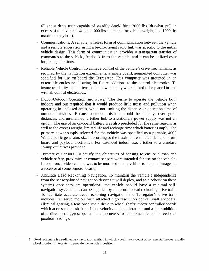
6” and a drive train capable of steadily dead-lifting 2000 lbs (drawbar pull inexcess of total vehicle weight: 1000 lbs estimated for vehicle weight, and 1000 lbsmaximum payload).
• Communications. A reliable, wireless form of communication between the vehicleand a remote supervisor using a bi-directional radio link was specific to the initialvehicle design. This form of communication provides a transparent transfer ofcommands to the vehicle, feedback from the vehicle, and it can be utilized overlong range missions.
• Reliable Vehicle Control. To achieve control of the vehicle’s drive mechanisms, asrequired by the navigation experiments, a single board, augmented computer wasspecified for use on-board the Terregator. This computer was mounted in anextensible enclosure allowing for future additions to the control electronics. Toinsure reliability, an uninterruptable power supply was selected to be placed in-linewith all control electronics.
• Indoor/Outdoor Operation and Power. The desire to operate the vehicle bothindoors and out required that it would produce little noise and pollution whenoperating in enclosed areas, while not limiting the distance or operation time ofoutdoor missions. Because outdoor missions could be lengthy, over greatdistances, and un-manned, a tether link to a stationary power supply was not anoption. The use of an on-board battery was also precluded for the same reasons aswell as the excess weight, limited life and recharge time which batteries imply. Theprimary power supply selected for the vehicle was specified as a portable, 4000Watt, electric generator, sized according to the maximum estimated demand of on-board and payload electronics. For extended indoor use, a tether to a standard15amp outlet was provided.
• Protective Sensors. To satisfy the objectives of sensing to ensure human andvehicle safety, proximity or contact sensors were intended for use on the vehicle.In addition, a video camera was to be mounted on the vehicle to transmit images toa receiver at some remote location.
• Accurate Dead Reckoning Navigation. To maintain the vehicle’s independencefrom the sensory-based navigation devices it will deploy, and as a “check on thesesystems once they are operational, the vehicle should have a minimal self-navigation system. This can be supplied by an accurate dead reckoning drive train.To facilitate accurate dead reckoning navigation1 the Terregator’s drive trainincludes DC servo motors with attached high resolution optical shaft encoders,elliptical gearing, a tensioned chain drive to wheel shafts; motor controller boardswhich access motor shaft position, velocity and acceleration; and a later additionof a directional gyroscope and inclinometers to supplement encoder feedbackposition readings.
1. Dead reckoning is a rudimentary navigation method in which a continuous count of incremental moves, usuallywheel rotations, integrates to provide the vehicle’s position.

16
• Payload Area. To accommodate experimental or other payloads, one half of theelectronics enclosure and the entire top surface of the vehicle were to remainunused by vehicle components.
These descriptions were used as the Terregator’s initial design specifications. These vehiclefeatures have evolved into the final configuration described in the following chapters.

17
4. Terregator Vehicle Description
4.1 IntroductionThe Terregator is an outdoor vehicle designed to deploy experimental navigation devices. Itis a six wheeled, skid-steer, remotely operable vehicle which can self-navigate to acommanded destination using on-board computer control and orientation sensing devices.Supervisory commands which assist this navigation can also be given by an off-boardcomputer or a human operator through a remote console and a transparent radio link. Thevehicle and the experimental navigation devices which it has been designed to carry areboth still under development. However, the near future promises a working coordination inwhich the navigation devices will sense the terrain and obstacles near the vehicle andactively guide the vehicle through unknown environments without human supervision. Toexplain the vehicle’s function, operation, and compatibility with navigation or controllingsystems, are the following sections describe of the vehicle’s components and their generalconfiguration.
4.2 General ConfigurationThe Terregator has six major subsystems: locomotion, power, control, communication,orientation, and a remote console. The locomotor consists of a mechanical drivetrain and asupport frame. The power system generates and distributes power and protects sensitivecomponents. The control system consists of a microcomputer and periphery.Communication is achieved through wireless RS-232 and microwave links. The orientationsystem has a gyroscope for heading information and two inclinometers for pitch and rollreadings. The remote console houses offboard components for operating the vehicle.
The Terregator, Figure 4-1 on page 18, is a rectangular base frame with six wheels, threeon either side. From the front and rear of the base frame, four vertical members of thesquare tube roll frame extend upward. These members support the upper horizontalmembers of the roll frame that form a rectangular envelope around the top of the vehicle.The rack mount enclosure is suspended from these upper members at six points such that itis not in direct contact with the base frame, isolating the rack mount enclosure from shockor vibration that might be transferred from the base. The sides of the cabinet adjacent to thewheels are covered by removable panels; the top of the cabinet is used as an uppermounting deck. The rack mount enclosure is located above the base frame extending fromthe front of the vehicle, back about two-thirds of the vehicle’s length. The remaining thirdof the vehicle’s top plate is covered by the power generator, mounted directly to the baseframe and remaining within the protective envelope of the roll frame. The vehicle is about3’ high, 3.5’ wide, and 5.5’ long.

18
Figure 4-1 Terregator
The function of each subsystem is as follows:
• Locomotor: Supports, protects, and mobilizes the vehicle and experimentalpayloads.
• Power: Generates and distributes power for all vehicle electronics and providesuninterruptable power to sensitive electronics.
• Controller: Processes motion commands and controls vehicle motion.

19
• Telemetry: Bi-directional link allows high-level commands and data to betransferred between vehicle and supervisor.
• Orientation: Sensors detect the vehicle’s orientation and provide feedback to thenavigation devices.
• Infrastructure: Supports the vehicle before, during and after its expeditions.
The following descriptions specify each component’s function, summarize its appearanceand composition, identify its association with other vehicle components, and specify powerrequirements where appropriate. Additional component drawings, photographs, and wiringdiagrams are included in the appendix, along with itemized listings of the vehicle’s power
The vehicle presently navigates through its environment and hosts navigation experimentsusing the integration of on-board components, wireless telemetry, and a remote console.Major on-board components include the mechanical drive train and support frame, theelectronic control system, the radio and microwave communication units, the orientationsensing devices, and the power generation, distribution and interrupt protection system.The off-board remote console is a peripheral link to supervisory computers and/orpersonnel; it houses a radio communication transceiver, a video receiver and monitor, andan operator terminal. Although this station is essential to the operation of the vehicle, it isonly a rough composition of peripheral electronics and was not part of the major vehicledevelopment. Therefore, this off-board component will be described only briefly followingthe specification or the vehicle’s on-board control components.
4.3 LocomotorThe locomotor transports, houses, and supports all onboard vehicle components, as well asany experimental devices or payloads. A skid-steer locomotor was chosen with a groundclearance of 6”. The locomotor has a drive train capable of steadily dead-lifting 2000pounds. Two banks of three drive wheels are each linked to two electric motors via chain-on-sprocket drive and gearing. The locomotor’s base frame houses these drive components,as well as supporting the upper roll frame, electronics cabinet, and power generator. Thethree main structural components of the locomotor are the base frame, the roll frame, andthe rack mount enclosure. They house and support the vehicle’s drive train and electronics.The roll frame is the locomotor’s prominent superstructure; it supports and protects thevehicle’s rack mount enclosure. The rack mount enclosure houses the vehicle electronics
20
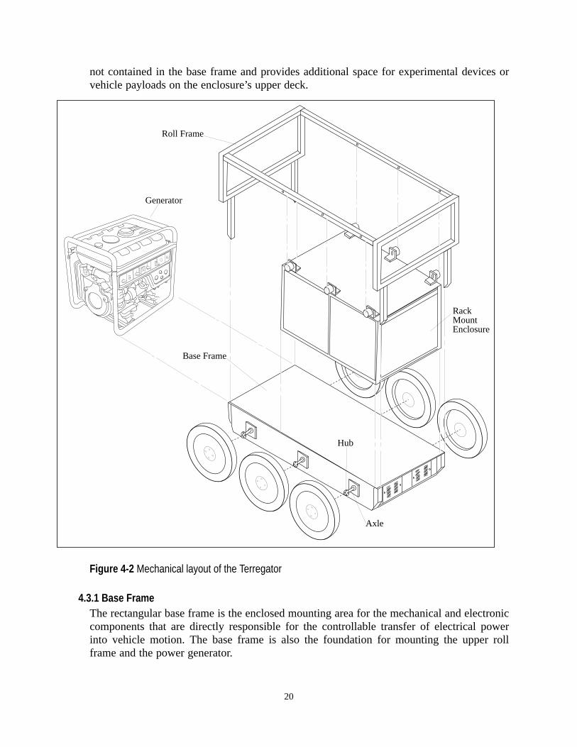
not contained in the base frame and provides additional space for experimental devices orvehicle payloads on the enclosure’s upper deck.
Figure 4-2 Mechanical layout of the Terregator
4.3.1 Base FrameThe rectangular base frame is the enclosed mounting area for the mechanical and electroniccomponents that are directly responsible for the controllable transfer of electrical powerinto vehicle motion. The base frame is also the foundation for mounting the upper rollframe and the power generator.
Hub
Axle
Base Frame
RackMountEnclosure
Roll Frame
Generator

21
The base frame is a steel box, see Figure 4-3 on page 22, 26” wide, 59” long, and 8” deep,elevated 6” above the ground by the vehicle’s wheels. The internal components of the baseframe are concealed by a top plate that has threaded mounting holes centered on a fourinch grid. This hole pattern is used to attach the generator and other equipment to the baseframe. Mounted on the inside of the base frame’s front and rear walls are four ventilationfans that draw cooling air through the base frame. The drive axles extend through sixbearing blocks supported by the side walls of the base frame support. Mounting holesthrough the side and bottom walls of the base frame are used to secure these and the othermechanical drive and electronic components contained within the base frame. A C-sectionstiffening plate is welded to the underside of the bottom plate to prevent lateral torsion ofthe base frame. A transverse stiffener across the top of the base frame also prevents theside walls from bowing outward when loaded.
The base frame and its enclosed components form a unit that is electrically andmechanically separable from other vehicle components. Detachable connections betweenthe base frame and the upper roll frame are found at four external mounting blocks on thefront and rear walls of the base frame. The generator is also bolted to the base frame on therear section of the top plate. The only electrical connections to the base frame are twocables that terminate inside the base and have connectors mated inside the rack mountenclosure. One cable provides power to the base frame electronics and the other transferscontrol signals and data to and from the drive motors.
4.3.2 Motors and Drive TrainWithin the enclosure of the base frame, the two drive motors are linked to the mechanicalcomponents of the drive train, i.e. gears, sprockets and chains. Each bank (left and right) ofthree wheels on the vehicle is driven by a single motor linked to an independent gearingset, sprocket combination, chain drive, and set of three wheel axles. The two driveassemblies for the left and right banks of wheels are identical, but they operateindependently to steer the vehicle. The motors can be driven in either direction, thuscausing the vehicle to move forward, back, left or right.

22
Figure 4-3 Terregator base frame and interior components.
The motors are brushed, electric, 120 VDC with attached optical shaft encoders. Eachmotor is coupled to Harmonic Drive gearing through an adapter plate, and the outputfrom these gearing units is 80:1. The main drive sprocket attached to the output shaftof the gear unit can be changed to alter the vehicle’s top speed and climbing torque.The top speed available from such a change-out is 4.8 mph.
The motor and gear assembly drives the wheel axles through a series of drive chainsand sprockets, See Figure 4-4 on page 23. The first, or primary chain, passes aroundthe main drive sprocket on the gear assembly out put shaft and then onto the centeraxle sprocket. The center axle sprocket then drives the front and rear axle sprocketsthrough the secondary chains. All drive chains are #58 5/8 lifetime lubricated chains.The chains are isolated from the environment by the confines of the base frame, butare not shielded further.
MotorHarmonic DriveAmps Idler Sprocket

23
Figure 4-4 Axle Assembly
During assembly and periodic maintenance, both sets of chains can be tensionedindependently. The primary chains are tensioned by loosening the motor mounts, slidingthe motors to reposition the main drive sprocket, and then tightening the mounts. Thesecondary chains are tensioned using stationary idlers attached to the interior side wall. Oneach side wall there are two stationary tensioners: one between the center and rear axles totension the rear secondary chain, and one between the center and front axles to tension thefront secondary chain.
Each of the six driven wheel axles carries a drive sprocket on the interior of the base frameand extends through the side walls to support a hub and wheel. See Figure 4-6 on page 26.The axles are aligned and supported along the center line of the base frame on independentstubs, and again at the side wall by a greased flange roller bearing. All sprockets in thedrive train are held in place on their respective axles by split taper bushings and key-ways.Hubs, located on the outside portion of each wheel axle, are mounted in a similar mannerand can be positioned anywhere along the exterior portion of the axles. This flexiblepositioning of the hubs accommodates wheels of differing widths. The wheel rims arebolted to the four studs on each hub.
Several different wheels, each consisting of a rim and pneumatic tire, can be used on thevehicle for a range of traction, ground clearance, side clearance, and dead reckoningaccuracy. The tires are all-terrain vehicle tires. Low pressure, 20” x 7” knobby tires providea large amount of traction and are designed primarily for climbing over obstacles or steepinclines. These tires elevate the base frame about 5” off the ground and make the vehicle41” wide, but decrease the dead-reckoned precision because of their compliance.
Other tires used include high pressure, 20.5” x 5”, shallow tread tires that are used forsmall farm equipment and have fair traction characteristics. On the vehicle, these tires areused for low grades and flat surfaces, and they are still able to carry the vehicle overobstacles such as stairs. With these tires, the vehicle’s ground clearance is about 6” and thevehicle width is 37”. These high-pressure tires increase the vehicle’s dead reckoningaccuracy because they do not deform significantly. Both types of wheels can be mountedon the hubs, and although the standard configuration is to have all six tires of the sametype, alternate configurations include mixing tire types among the six wheels. Experimentswith the vehicle primarily use all six knobby tires, although a configuration of knobby tireson the center wheels and smoother tires on the front and rear has been tried successfully.
Chain Tension Idler
Front Secondary Chain Motor
Primary Chain
Rear Secondary Chain


25
carrying the signal communications line in a similar but continuous route from the wireduct around the motors.
Inside the amplifying unit, +10 volt and -10 volt signals from the motor controllers areused by each amplifier to modulate the power to the motors, which is in the form of 100VDC pulses. This requires that the 72 VAC from the transformer be changed to 100 VDCthrough a diode bridge before entering the amplifiers. Each motor is regulated throughindependent amplifiers. As modulated power exits each amplifier, it is cleaned by aninductor and then routed back through the power conduit to each motor. Once power isreceived and consumed by the motors, encoder feedback of motor shaft rotation is routedthrough the signal communications conduit and returned to the motor controllers. Theamplifying unit also provides 120 VAC for the front cooling fans.
4.3.3 Roll FrameThe roll frame protects and supports the rack mount enclosure. It protects the enclosurefrom possible damage inflicted either by obstacles protruding into the enclosure or bysudden contact with the ground during a roll-over. The roll frame supports the rack mountenclosure from six mounts along its upper horizontal members. These mounts arecompliant neoprene cylinders that act in pure shear to prevent large impulsive forces frombeing transferred to sensitive electronics housed in the rack mount enclosure. Thismounting system suspends the enclosure 2” above the top plate and allows it to displacevertically and horizontally while dissipating jolts.
The roll frame forms a protective envelope of 1.5” square steel tubing around the rackmount enclosure and the generator. See Figure 4-2 on page 20. The vertical end frames,bolted to the front and rear of the base frame, extend slightly beyond the leading edges ofthe generator, the rack mount enclosure, and the base frame. These end frames arepermanently welded to the horizontal upper members. The upper members run along thelength of the vehicle, above the enclosures and generator, and are spaced slightly wider


27
Front Compartment• The Multibus Enclosure for onboard computing electronics is mounted on rack
mount sliding guides in the upper half of the cabinet. This unit can slide out overthe right side of the vehicle and is covered by a 7” wide panel on the exterior of theenclosure.
• The Uninterruptable Power Supply (UPS), located directly below the Multi-busenclosure in the front compartment, is bolted to the rack mount frame. The front ofthe UPS is covered by a 10.25” louvered ventilation panel located on the right sideof the enclosure.
• Two Cooling Fans are mounted on the interior of the front cabinet, immediatelybehind the Multibus enclosure. They are attached to the 8.75” panel that covers therear of the Multibus enclosure, located on the left side of the front cabinet. Thefans draw air through two grilled openings in this panel and into the rack mountenclosure to cool the electronics and the UPS.
• The Power Distribution Box, located below the cooling fans on the left side of thefront cabinet, is bolted to the rack mount frame directly behind the UPS. The boxis covered by an 8.75” panel and has a block of four circuit breakers extendingthrough an opening in the panel.
Rear Compartment• The Radio Transceiver, mounted on sliding rack mount guides in the bottom of the
rear cabinet, has a cover panel permanently attached to its face. This unit can beaccessed by sliding it out over the right side of the vehicle. When the rack mountenclosure is mounted on the vehicle, this operation also requires removal of theright center wheel because the radio unit is located slightly below the top of thistire. The rear of this unit is covered by a 7” panel on the left side of the enclosure.
• The Orientation Sensing Unit, containing one gyroscope and two inclinometers, ismounted above the radio transceiver on sliding guides. It is covered by a 12.25”panel and can slide out over the left side of the vehicle, above the wheels. The rearof this unit is covered by a 12.25” panel on the left side of the rack mountenclosure.
• The Switching Panel provides on/off control of devices mounted on the Terregator.
The rack mount cabinet is located over the front two-thirds of the base frame, but it doesnot come into direct contact with the base frame. The enclosure is shock mounted to theroll frame and rides 2” above the top plate. The rack mount enclosure can be detachedfrom the vehicle by unbolting the roll frame and lifting it off with the enclosure attached,or by unbolting the enclosure from its mounts on the roll frame and lifting it offindependently. When the enclosure is removed from the vehicle, the power and controlcables routed into the enclosure from the generator and base frame must be disconnected.The cable that brings power to the vehicle (via the generator or wall outlet) is routed fromits soldered connection at the power distribution box within the enclosure, through theenclosure’s wire duct, to a 30 amp connector outside the enclosure. When removing theenclosure, this cable is disconnected and the length of cable with the female connector endremains with the enclosure.

28
A second cable, transferring power to the base frame, is routed from an outlet plug on thedistribution box to a soldered connection in the base. The routing of the signalcommunication line from the Multi-bus enclosure to the base frame is made in a similarway using an RS-232 connector at the rear of the Multi-bus enclosure and a solderedconnection to the amplifying unit in the base frame. Both of these conductors, whichterminate in the base frame, must be disconnected inside the rack mount enclosure andthreaded out through the wire duct when the enclosure is being removed from the vehicle.
4.4 On-Board Control SystemAn augmented mono-board microcomputer controls the vehicle’s drive mechanismsonboard. This microcomputer is mounted in an extensible enclosure allowing for futureadditions to the control electronics.
The two primary operations of the onboard control system are the processing of motioncommands and position information. Both of these operations are essential to the completeexecution of command flow from offboard supervisors to the vehicle’s positioning systems.The vehicle’s onboard control system consists of a central processing unit (CPU) linked tomotor controllers, an analog-to-digital converter (ADC), a serial line expander, andorientation devices. The CPU receives commands from an offboard supervisor andexecutes programs residing in onboard memory to transfer the appropriate signalcommunications to the motor controllers. The onboard supervisory software programs arecontinuously evolving to meet the needs of experimental deployments by offering a varietyof commands to operate the vehicle.
The offboard supervisory control is distinguished as high-level control in comparison tolow-level, onboard control. This distinction is made to emphasize the different types ofcontrol that are involved in the vehicle’s operation. At the remote console, the supervisor(either a human user or a another computer) makes high-level decisions that specify goaldestinations and orientations. These complex commands are conveyed to the vehicle andthen decomposed by the CPU into low-level commands that directly control the onboarddevices responsible for the vehicle’s motion, position, and orientation.
During vehicle operations, the onboard computer maintains a data structure to inform thesupervisor about available high-level command options and the status of the low-levelcontrol operations. The user can access information about valid commands, the vehicle’slocation, and its orientation. This information is displayed on the remote station terminal orcan be accessed by the offboard computer. The display is always available during vehicleoperations that involve low-level control by programs residing in onboard memory.
All programs for the on-board control of the vehicle are written in the C programinglanguage and are retained by the CPU’s. non-volatile memory. Additional or alternatesoftware can be down-loaded to the vehicle’s processor from off-board computers,allowing a variety of operating schemes. The operating scheme presently in use on thevehicle offers the user numerous commands, some of which are point to point movescomprising the following basic commands:
• The Move command takes as its argument a distance measured in millimeters. Thevehicle then translates either forward or backward.

29
• The Turn command takes as its argument an angle measured in degrees. Thevehicle then pivots to the right or left on its center wheels.
• The Arc command executes an arc-shaped path between two points. Thearguments required are a distance in the Y direction (along an axis running fromthe center to the front of the vehicle), the X direction (transverse to the Y axis), andan angle orienting the destination state relative to the initial state. As with theprevious commands, distances are measured in millimeters and angles in degrees.
Also available are several commands which can be used to “drive” the vehicle while it is inmotion. As the vehicle travels in a continuous path composed of arcs, the direction of its


31
commands. The other communication port on the CPU remains open to be linked with anyprocessors that may be placed on-board to supplement experimental payload operations.
Control signals communicated to the CPU over the bi-directional radio link are processedby the CPU and then routed through a serial expansion board and a 16/32 channel A/Dboard. Low level commands corresponding to motor control are routed from the CPU,through the interrupt driven serial expansion board, to the motor controllers. The A/Dboard (also interrupt driven) is accessed by the CPU to obtain position and orientationreadings from the gyroscope and inclinometers. These devices are remote to the multi-busenclosure, but are connected to the unit through a ribbon cable entering the front of themulti-bus. The A/D board, located on a board adjacent to the serial board, also returnsencoder status to the CPU along the same route.
Control of the vehicle’s drive motors is performed by two DC servo motor controllersmounted together on a blank board inside the multi-bus enclosure. Each motor has adevoted controller, which receives instructions from the CPU and operates the poweramplifiers located in the base frame. The motor controllers operate using direct positionfeedback from the motor encoders, and can be operated to control the motor position,velocity and acceleration.
Each electronic component is mounted in one of ten slots provided by the enclosure’s busstrip. Power is provided to electronic components inside the Multibus through a 40 wattpower supply connected to the UPS. These components are cooled by two 50 cfm fansmounted inside the Multibus enclosure. The enclosure was slightly modified by attachingrack mount sliding guides and replacing the front panel on the unit. The Multibus is locatedin the front compartment of the vehicle’s rack mount enclosure and can slide out over theleft side of the vehicle. The electrical power for this unit, supplied by the UPS, is accessedthrough a terminal strip in the rear cabinet. Power to the radio transceiver from one of two110 VAC outlets is also located in the rear of the unit.
4.4.1 Joystick ControllerA joystick controller allows manual operation of the vehicle. When in use, this device is setto override any other control systems, i.e. the on-board computer or off-board supervisor.The joy stick is used primarily as a method of maneuvering the vehicle while softwaremaintenance and development are ongoing. This device is considered only a temporarymethod of controlling the vehicle, and will no longer be of use once the vehicle’s softwarecontrol is completed.
The joystick is a rectangular metal box, approximately 4” by 5”, with several switches onits top surface. The joystick is connected directly to the vehicle’s motor controller boardsvia a tether. The control override button which is located on the joystick is used to shift thevehicle between computer control and joystick control, and also serves as an emergencykill button, immediately stopping the vehicle’s motion. Separate control of the vehicle’s leftand right banks of wheels can be achieved using two independent toggle switches locatedadjacent to the override button. A final button, located in the center of the joystick, isdepressed to enable the drive motors. Note that the motor velocity and acceleration cannotbe set from the joystick, (programed default values are used) and vehicle position andorientation information is not available.
32
4.5 Remote ConsoleThis console houses the off-board components associated with the vehicle’s operation. Itprovides rack mount storage areas for communication and control components such as anoperator’s terminal, the stationary radio transceiver, the microwave receiver, and videomonitors. The remote console is mounted on castors, and is thus moderately portable.
4.6 Telemetry SystemTwo telemetry links transfer information between the vehicle and the remote commandstation. The primary information link is a bidirectional radio transceiver that is used totransmit control and feedback data. A secondary link is provided by a microwave videotransmitter that sends images from the vehicle to the remote command station.
4.6.1 Radio Serial Rs-232 LinkThe radio link is formed by two identical transceiver units; each unit is capable of bothtransmission and reception of signals on the appropriate wavelength. One unit is located inthe remote command station, and serves to transmit supervisory commands to the vehicle.This stationary unit also receives data on the vehicle’s position, orientation and thecommands which are available through the vehicle’s on-board computer. The othertransceiver, mounted on the vehicle, transmits the position, orientation and commandstatus, and receives the supervisory control commands from the remote station. Theinformation exchange between these two transceivers forms a transparent link thatfacilitates controlled vehicle operations in areas remote from the command station.
Radio transmissions occur over licensed FM frequency in the 400 MHz range. Eachtransceiver is an RS232 full duplex modem, transmitting data at 1200 baud, and usingmanchester keying protocol. The power requirements of this unit are provided by a 12 Voltpower supply attached to the back of the transceiver. The mobile radio transceiver is rackmounted on the vehicle and slides into the bottom of the rear cabinet. The antenna for thisunit is bolted to the top plate of the rack mount enclosure.
4.6.2 Microwave Video LinkThe microwave video link is a 2 GHz system that transmits visual images from a singlecamera on-board the vehicle to a monitor in the remote console. This information is usedprimarily to test vision-based navigation experiments.
The camera is mounted on a rigid tripod which reaches to a height of about 6 ft. Thisassembly is bolted to the top plate of the rack mount enclosure and can be relocatedanywhere on the top plate. An actuated, self-leveling pan and tilt for this camera is beingdeveloped to replace the tripod, and will reside on top of the front compartment of the rackmount enclosure.
4.7 Orientation SensorsTwo kinds of on-board orientation sensors provide information on the vehicle’s orientationrelative to a set coordinate frame. The primary sensor is a directional gyroscope whichreports the angle through which the vehicle rotates in the horizontal plane. The secondarysensor is a dual axis inclinometers which determines the vehicle’s rotation about its lateral

33
and transverse axis. The information provided by both sensors is used by the vehicle’snavigational software to maneuver the vehicle through turns and/or maintain a constantheading. These sensors are mounted on a common plate in the rack mount enclosure alongwith the accessory electronics, such as power supplies and data processing units, that theyrequired to operate.
4.8 Power Supply SystemThe power supply components supply, distribute, and protect against interruption ofelectrical power onboard the vehicle. Power is supplied to the vehicle either by the onboardgenerator or an extension cord connected to a wall outlet. These alternate power sourcesare available to cater to different operating modes. The onboard generator is used duringoutdoor operations that may cover large distances. A stationary, offboard power source forthe vehicle is used when the vehicle is operated in confined areas where noise and fumesfrom the generator are offensive. Power distribution to all onboard electronics originatesfrom the main distribution box and is transferred to vehicle electronics through a conductornetwork. An Uninterruptable Power Supply provides clean, continuous power to thevehicle’s control system and maintains the controlling software in the event of a loss ofnormal power.
4.8.1 GenerationWhen operating outdoors, the vehicle uses a gasoline powered, 4000 watt, portablegenerator to supply all onboard power. See Figure 4-8 on page 34. This unit is positionedbetween the vehicle’s rear wheels and mounted to the top plate of the base frame. Itsupplies 120 VAC directly to the distribution box via a 50 amp connector and cable.
The generator consists of an air cooled, electric start, 4-stroke, single cylinder engine witha displacement of 406cc and a compression ratio of 6.8:1. It operates at 3600 rpm and has arated draw of 32 amp. The rated AC output frequency is 60 Hz and the DC output issufficient to charge a 12 volt starting battery. The generator is approximately 26” long, 17”wide, 24” high, and weighs 187 lbs. A 4.4 gallon gas tank allows the generator to run for

34
six hours. Vibration insulating mounts are situated between the mounting tabs and theengine mounts to prevent the transfer of excess vibrations.
Figure 4-8 Power Generator
Modifications made to the generator for use on the vehicle included altering the outputplug, redesigning the battery mount, and mounting the generator to the base frame.Because the generator is positioned directly behind the rack mount enclosure, the originaloutlet plug was not accessible by the conductor coming from the distribution box. Anoutlet box was made from stainless steel and attached to the left side of the generator (overthe left side of the vehicle). This outlet contains a 50 amp female receptacle that has beenwired to the original generator outlet. Attached to the present receptacle is the re-designedbattery mount. The battery mount was relocated because the original mount extendedoutside of the roll frame’s protective envelope. The present mount is a stainless steel box,open on top, and supported by a bar attached to the generator’s frame. The generator wasmounted to the base frame with a steel plate bolted over the generator’s mounting frame.This plate holds the generator stationary and did not require any modification of thegenerator’s mounting frame.
For prolonged periods of operation indoors, the vehicle can be connected to any available120 VAC outlet equipped with a 15 amp grounded receptacle. A 100’ extension cable wasmade specifically for this purpose. It has a 50 amp, twist lock, female connector thatattaches to the vehicle and a 15 amp male connector to plug into wall outlets.
Oil Alert Switch
DC Circuit Protector
AC Circuit Breaker
Ground Terminal
AC Receptacle
DC Terminals
Engine Oil Filler Cap
Engine Oil Drain Plug
Recoil Starter Grip
Fuel Valve
Engine Switch
Auto-Throttle Switch
Voltage Selector SwitchVolt Meter Pilot Lamp

35
4.8.2 Distribution PowerThe distribution box allocates power to the vehicle’s electronic components and preventsthese components from overloading the main electrical circuit. The distribution box routesthe main power through a block of circuit breakers to the base frame, the UninterruptablePower Supply (UPS), and the rack mount enclosure’s cooling fans.
The cable that transmits power to the circuit breakers, wired directly to the block of fourbreakers and a ground strip, passes through a strain-relief duct in the wall of thedistribution box. There are three 15 amp breakers and one 30 amp breaker. All breakers,except an unused 15 amp breaker, are wired to bulk-head connectors in the side of thedistribution box. The 30 amp connector is devoted to the conductor that transmits power tothe base frame electronics. One 15 amp connector is used to transmit power to the UPS,and the remaining connector is used to supply power to the rack mount enclosure’s coolingfans.
The distribution box is a modified commercial enclosure and can be accessed through thebottom panel on the left side of the rack mount enclosure. The box is 10” x 8” x 4” andcontains the four-breaker block, a ground strip, and three bulkhead connectors. The box isattached to an aluminum mounting bracket and bolted to the bottom of the rack mountenclosure, directly behind the UPS. The interior of the box can be accessed by removingthe panel that covers this portion of the enclosure. The circuit breakers remain exposedthrough a square cut-out and can be reset without removing the panel.
4.8.3 ProtectionIn addition to the circuit protection provided by breakers in the distribution box, theUninterruptable Power Supply (UPS) protects the vehicle’s electronics from being over orunder powered. The UPS insures uninterruptable power to the computing components,especially in the event of a loss of primary power to the vehicle. The UPS also providescontinuous, regulated, and noise-free power to the computing components during normalpower supply conditions.
The UPS consists of three basic parts: the rectifier, the inverter, and the battery. Therectifier takes in AC power, delivers DC to the inverter, and recharges the battery. Theinverter converts DC power to AC power at 120 VAC. The battery is continuously chargedby the rectifier until the power fluctuates or is interrupted. This power filtration systemalleviates various problems that can occur during motor-generated power such as voltagedips, black outs, frequency variation, or momentary interruption.
The UPS on the vehicle is rated by the manufacturer to have an output of 750 watts at afrequency of 60 Hz and 120 VAC.

36
5. Evaluation and Conclusions
5.1 EvaluationsAs the Terregator is part of an evolving technology, it is essential to acknowledge thesuccesses and failures of this vehicle’s design. This evaluation will begin with a discussionof the vehicle’s failures and successes in meeting the specific objectives outlined in earlierchapters. The vehicle satisfies most of the design objectives, and therefore this evaluationwill only discuss points of extreme failure or success.
Perhaps the vehicle’s largest shortcoming is its inability to self-navigate over great rangeand variable terrain. The indeterminacy of skid steering limits the achievable accuracy ofdead reckoning by step counting. The inherent skidding which occurs during turningmotions limits the usefulness of maintaining incremental counts of wheel rotations as adeterminate measure of travel distance. This source of somewhat subtle error is not easilynullified by some “fudge factor”. The error incurred in a turning depends on the roughnessand inclination of the ground surface.
Deficiencies of the locomotor include its incomplete seal against moisture. One problem isthe ventilation into the base; although filtered for dust, the ducts can inhale water into thebase, threatening the operation of several electronic components. Additionally, there is anupper bound on onboard power available for experimental payloads. Payloads are alsolimited by available space on top of the Terregator and by the number of componentsinside the rack mount enclosure.
Distinguishing features of the Terregator include its climbing and maneuvering ability.Stairs, curbs and other obstacles approximately 6 inches high pose no difficulties. Skidsteering has given the vehicle considerable maneuverability with mechanical simplicity notfound in complex axle steering mechanisms. Pivoting turns allow navigation in constrictedareas and precludes the need for complex planning and maneuvering required to navigatethree-point turns. Finally, the vehicle’s motion control is flexible, motor acceleration andvelocity control is precise, and the Terregator is compatible with interactive navigationexperiments.
5.2 ExperimentsBrief descriptions of three Terregator experiments that demonstrated perceptivenavigation, and a fourth in progress, follow. More detailed descriptions of theseexperiments can be found in articles listed in Appendix II: Terregator Research.
In the first experiment, the Terregator followed a road through a park. Using a videocamera to collect data about the road, the system computed gradients throughout the imageto detect the road edges, and then plotted a course down the middle of the road. In anotherexercise, the Terregator navigated off road using range data (sonar, laser, or stereo video) tonavigate around trees.
In the second experiment, we adapted the Terregator to navigate a network of campussidewalks. See Figure 1-1 on page 8. This adapted system consisted of a vision subsystem,a navigator, a predictor, a position estimator, and a map of the network. Given the goal

37
“proceed to intersection seven,” the Terregator plotted a course through the network,calculated a predicted model of the scenery expected on the way, and used the observedsensor data to verify its course, correcting the estimated position along each step of thepath.
In the third experiment, the Terregator mapped and navigated a portion of a coal mine. Thisexperiment integrated the Terregator’s local navigation software and acoustic sensing witha composite model builder. The Terregator traversed a short piece of the mine, mapping thewalls and creating a network of seventeen goal positions. The map was proven to beaccurate and the integrated system performed flawlessly. Subsequently, the Terregatornavigated the same mine using data from the scanning laser range finder and made turningdecisions based on its generated map. See Figure 5-1 below.
The Terregator currently deploys a mobile scanner used for experiments in mappingsubsurface pipes. The scanner, a wheel mounted, single axis gantry, deploys varioussensors along a path transverse to the vehicle’s motion. The Terregator was selected as thedeployment vehicle because it allows controlled maneuvering of the gantry, is equippedwith a suite of sensors for position encoding, can host necessary scanner computing, and isproven for field use.
Figure 5-1 Terregator with laser scanner navigating in a coal mine.

38
5.3 ConclusionThe Terregator has been a very successful project. The vehicle is transporting andinteracting with experimental payloads in outdoor environments. The Terregator has beenwell conceived, speedily produced, and well received. The vehicle is modular and remainsadaptable to a variety of uses and operating environments.
This project did not intend to create the “ultimate” autonomous vehicle, and it is notsurprising that there is a call for upgrades to the present vehicle. These may includeadditional on-board power, computing, payload area, and improved navigation abilities.The Terregator can endure some extensive revisions and change-outs without losing itsinitial identity or negating its purpose. But when these alterations become significantenough the threaten that identity, then it is perhaps prudent to allow newer vehicles,siblings to the Terregator, to overcome its deficiencies

39
A. Weight and Power Budgets
A.1 Itemized Vehicle Weight• Locomotor Weight
• Wheels and axles: 6 at 27 lbs. 162 lbs.
• Chains and sprockets: 50 lbs.
• Chassis frame: 170 lbs.
• Gearing: 2 at 60 lbs. 120 lbs.
• Motors: 2 at 27 lbs. 54 lbs.
• Amplifier: 16 lbs.
• Fans: 4 at 3 lbs. 12 lbs.
• Roll Frame: 70 lbs.
Subtotal 654 lbs.
• Environmental Enclosure
• Breaker Box: 12 lbs.
• Enclosure housing: 105 lbs.
• Multibus: 40 lbs.
• Uninterruptable power supply (with batteries): 120 lbs.
• Radio: 30 lbs.
• Fans: 2 at 3 lbs. 6 lbs.
• Power Supply: 5 lbs.
• Hardware: 10 lbs
Subtotal 328 lbs.
• Primary Power Supply
• Generator: 200 lbs.
• Battery: 5 lbs.
Subtotal 205 lbs.
• Collision Prevention Device
• Bumper 15 lbs.
Total Vehicle Weight: 1530 lbs.

40
A.2 Itemized Power Budget Maximum Demands for Vehicle Operations
• Drive motor amplifiers (2 at 1400 watts each) 2800 watts
• Motor control boards 40 watts *
• Multibus 225 watts *
• 68 K boards 60 watts *
• Radio 60 watts *
• Ventilation fans (6 at 50 watts each) 300 watts
• IR collision sensors 60 watts *
Total 3545 watts
Maximum Power Supplied to Vehicle 4000 watts
Maximum Power Available for User 455 watts
* UPS Protected 445 watts

41
B. Bibliography
1) Adams, Walt, “Robot Vehicles Move Into Manufacturing”, Robotics Today ‘82Annual Edition, Robotics International Society of Manufacturing Engineers,Dearborn,Michigan; 1982.
2) Apollo Program Summary Report, “Vehicle Development and Performance, LunarSurface Mobility”, National Aeronautics and Space Administration Houston,Texas; 1975.
3) Billet, A.B., “RCV-150 Remotely Operated Vehicle and its Operation in theHostile Undersea Environment”, Proceedings of the Robotics and RemoteHandling in Hostile Environments National Topical Meeting, April 23-27, 1984;American Nuclear Society Inc., Chicago, Illinois.
4) Boyle, Stanley Robert, “Remote Working Vehicles For Use in NuclearEnvironments”, Masters Thesis Submitted to Civil Engineering Dept., Carnegie-Mellon University July 1984
5) Dobson, J.S.;Penoyre, S., “Automatically Controlled Road Vehicles”, Conferenceon Control Aspects of New Forms of Guided Land Transport, Institution ofElectrical Engineers; Savoy Place, London WC2; 1974
6) McNair, James M., “Designing Robots For Demilitarization of Obsolete ChemicalMunitions”, In Proceedings of the Robotics and Remote Handling in HostileEnvironments National Topical Meeting, April 23-27, 1984; American NuclearSociety Inc., Illinois.
7) Pollard, Brian W., “RAM for Robots: Reliability, Availability, Maintainability”,Robotics Today ‘82 Annual Edition, Robotics International, Society ofManufacturing Engineers, Dearborn,Michigan; 1982.
8) Whittaker, William L., “Terrestrial Navigator - Terregator”, A Proposal Submittedto The Defense Advanced Research Projects Agency, The Robotics Institute,Carnegie-Mellon University; July 1984.
9) Whittaker, William L., Personal Conversations Feb. 1983 - Dec. 1984.
B.1 Personnel AcknowledgmentsThe following persons were responsible for the design, production and early use of theTerregator Vehicle:
John Bares, Spencer Barrett, Steve Berman, Dale Birosh, Lee Bares (nee Champeny),Kevin Dowling, Kerien Fitzpatrick, Chris Fromme, Chris Harrington, Herman Hueng,Kathy Kelleher, Jim Kelly, Doug Larson, Keith Lay, Kai Lee, Rob Markovich, Jim Martin,Don Maszle, Tom Puckett, Susan Simone, John Wadsworth, Chuck Whittaker, RedWhittaker.

42

43
C. Addendum 1991
This Terregator Report has not seen the light of day for years due to many reasons, mostlyother projects. In December of 1984 Lee Champeny had compiled the first major draft ofthe document and in the following year Syd Coppersmith edited it. The effort neverreached critical mass and I picked it up in early 1991. In the meantime, the mysteriousTerregator technical report had been referenced many times by the CMU community!
I acquired the old Scribe versions from backups stored in salt mines. They were done an anancient DEC-20 machine and later versions were done on a VAX-750, also in Scribe. I thenreformatted the documents in Framemaker, visciously edited the text and finished it.Thanks to Mary Jo Dowling for creating shiny new Postscript versions of the drawings anddiagrams and to Mike Blackwell for getting this stubborn creature to print!
Over the years Terregator has become the centerpiece of many robotic works and as of thiswriting is being used by Jim Osborn’s Site Investigation Robot group to supportdeployment of ground penetrating radar devices for sub-surface mapping.
Terregator technical developments have moved to other machines and evolved over yearsinto large programs. This includes the Navigation Laboratory and HMMWV, driverlessvehicles for studying outdoor navigation and also the Locomotion Emulator for minevehicle emulation. This also includes the more recent planetary rover developments such asthe Ambler, Erebus and APEX programs. Additionally, some of the earliest development inrobot software architectures were first tested on the Terregator.
Changes over the years have included upgraded controllers and wiring. The originalMultibus 68K board system gave way to a i386 Multibus system using PL/M fordevelopment. In the late 1980’s a complete revamping of electronics resulted in a versatileelectronic patching system and a new VME bus based 68020 controller. New amplifierswere also installed at that time. Additional telemetry to support high-bandwidth devicessuch as new cameras and laser scanners were also added.
Through all of this, the general configuration and purpose of the machine has not changed.Plus, it keeps on ticking.
Kevin Dowling May 1991.

44

45
D. Recent Terregator Research
1) Christian, D.A., B. Motazed, J.F. Osborn, and D. White, “Automated SubsurfaceMapping,” 1989 Annual Research Review, The Robotics Institute, CarnegieMellon University, 1990.
2) Goto, Y., K. Matsuzaki, I. Kweon, and T. Obatake, “CMU Sidewalk NavigationSystem, Proc. of Fall Joint Computer Conference, pp 105-113, Nov. 1986
3) Hebert, M. and T. Kanade, “Outdoor Scene Analysis Using Range Data,”Proceedings, IEEE Conference on Robotics and Automation, April 1986.
4) Kanade, T., C. Thorpe, and W. Whittaker, “Autonomous Land Vehicle Project atCMU,” Proceedings, ACM Computer Conference, Cincinnati, OH, February 1986.
5) Osborn, J.F., “Automated Subsurface Mapping,” Proceedings of the SecondInternational Symposium on Field Screening Methods for Hazardous Waste andToxic Chemicals, Las Vegas, February, 1991.
6) Wallace, R., K. Matsuzaki, Y. Goto, J. Webb, J. Crisman, and T. Kanade, “Progressin Robot Road Following,” Proceedings, IEEE Robotics and AutomationConference, April 1986.
7) Wallace, R. A. Stentz, C. Thorpe, H. Moravec. W. Whittaker, and T. Kanade, “FirstResults in Robot Road Following,” Proceedings, International Joint Conference onArtificial Intelligence, Los Angeles, CA, August 1985.
8) Whittaker, W., “Cognitive Robots for Construction,” Annual Research Review,The Robotics Institute, Carnegie Mellon University, Pittsburgh, PA, December1985.
9) Whittaker, W. et al., “Mine Mapping by a Robot with Acoustic Sensors,”Proceedings of the Second International Conference on Robotics in Construction,Pittsburgh, PA, May 1985.
Whittaker, W. and I. Oppenheim, “Demonstration of Robotic Mapping of Mine Spaces,”Technical Report, Construction Robotics Laboratory, Pittsburgh, PA, April 1985.