Embed Size (px)
Citation preview

Page 238
November 15-18, 2006 São Paulo – Brazil
IIBCC 2006 - Sao Paulo, Brazil. October 15 - 18, 2006. Universidade de Sao Paulo & University of Idaho: Sao Paulo, 2006.
THE TECHNICAL SPECIFICATION OF MATRIX RAW MATERIALS FOR HATSCHEK TECHNOLOGY-BASED FIBRECEMENT.
- A PRAGMATIC APPROACH –
VAN DER HEYDEN, LUC
Redco N.V., Kuiermansstraat 1 - 1880 Kapelle-op-den-Bos, Belgium
ABSTRACT For many of the raw materials that are used in the matrix of fibrecement (FC) products, the FC industry constitutes a minor market only. Therefore the producers of most of these raw materials do not orient their production processes towards the needs of the FC industry, but towards that of their main markets, say, the concrete and the mortar industry. The same concrete and mortar orientation is observed in the worldwide academic and industrial research on cements, pozzolans and fillers as well as in the technical standards dealing with these materials.
On the other hand, the raw materials’ technical requirements that have to be met in view of the Hatschek technology-based FC application may differ quite a lot from that imposed by the concrete and mortar application. So, much more than in concrete and mortar industry, individual FC producers are forced to develop their own technical guidelines for the specification of their raw materials. A major point concerns the identification of the raw material characteristics that do have relevance for the FC production process and/or the FC product performance. Further the FC producers have to convince the raw material suppliers that the FC specific requirements should be satisfied as much as possible in order to assure workable FC production conditions as well as high quality FC products.
The present paper shows that such a FC-specific approach of raw material specification asks for an intimate mix of knowledge from different fields: the fundamental materials science, the raw material’s production process, the technical requirements defined by the major markets of the raw material, the FC production process as well as the FC product and its applications. Based on many years of practical, industrial experience, the above approach is illustrated for 2 commonly used matrix raw materials for air-cured FC: cement and condensed silica fume.
KEYWORDS: Fibrecement; specification; raw material; cement; condensed silica fume.
1. INTRODUCTION Most of the raw materials that are used in the matrix phase of air-cured FC products also constitute major components of the nowadays concrete and mortar products: Portland clinker-based cements, condensed silica fume, metakaolin, limestone flour, pulverized coal fly ash, expanded perlite, exfoliated vermiculite etc.. Since the concrete and mortar industry represents a significantly bigger market than FC, the raw material producers orient their production processes towards the needs of the first. The same concrete and mortar orientation is observed in the worldwide academic and industrial research on cements, pozzolans and fillers as well as in the technical standards dealing with these materials.

Page 239
November 15-18, 2006 São Paulo – Brazil
IIBCC 2006 - Sao Paulo, Brazil. October 15 - 18, 2006. Universidade de Sao Paulo & University of Idaho: Sao Paulo, 2006.
On the other hand, the raw materials’ technical requirements that have to be met in view of the FC application differ quite a lot from that imposed by the concrete and mortar application. So, many of the requirements of the general technical standards for cement and the other FC matrix ingredients are in most cases not relevant for the FC application. Moreover for most of the raw material suppliers the Hatschek technology-based FC process is a rather, if not fully, unknown production process. Moreover their understanding of the basic nature of the finished FC products is limited. This explains why most of them do not have a clear view on the raw material’s characteristics that determine their performance in FC.
Further, the technical layout of the very Hatschek line concerned, as well as the type of FC products that are made on it, may have an important impact on the required technical characteristics of one or more of the FC matrix raw materials.
Because of the above, the FC producer himself will have to define the technical requirements with real relevance for his FC production and FC product applications, and will have to convince its suppliers of the necessity to meet these requirements as much as possible. The elaboration process of the requirements includes the selection of the relevant characteristics as well as the definition of quantitative or qualitative criteria.
The present paper describes a pragmatic approach for the elaboration of FC relevant technical requirements for 2 commonly used matrix raw materials for air-cured FC: Portland clinker-based cement and condensed silica fume (CSF).
2. HATSCHEK PROCESS- AND FC PRODUCT-SPECIFIC ASPECTS WITH RELEVANCE FOR THE RAW MATERIALS SPECIFICATION.
2.1. The Hatschek process: a dynamic, multiparameter box
A description of the Hatschek process and machine falls beyond the scope of this paper. We just note that in a rudimentary way, the Hatschek machine can be described as a simplified and slowly running paper-making machine, or even better a cardboard-making machine. Hereafter the major Hatschek process-specific production parameters with relevance for the raw materials specification are just enumerated. It is believed however that by this, the big differences with the concrete and mortar applications are elucidated to a, in the context of this paper, already sufficiently large extent.
The FC mix preparation and feeding. The FC mix is prepared and fed in the form of a thin slurry (ca. 250 respectively 80 – 150 g solids/l). The raw materials should allow to keep the slurries homogeneous and stable until the moment of sheet formation on the machine.
The process water circuit. According nowadays technology the Hatschek process water is used in closed circuit. So the raw materials that are used must enable the fast and efficient cleaning of the backwater in the sedimentation cones and should not exhibit too much rapidly water soluble components in order to keep the process water’s dissolved salts content at low to moderate level.
The sieve. Great care has to be taken to avoid the use of raw materials that contain (even extremely low amount of) hard, stony particles in view of possible damage of the “vulnerable” sieve cloth. Additionally the raw materials should promote the development of a suitable flocculation structure in view of the obtainment of high sieve pickup ratio and smooth, homogeneous primary FC layers.
The felt. When selecting raw materials one has to take into account their possible adverse effects on the way in that, and the speed with which, the felt’s permeability is decreased with time by the gradual blocking of its porosity.
The vacuum system. For one and the same vacuum system, the machine speed (i.e. productivity) depends on many factors such as the type of felt used, the type of FC formulation, the flocculation system used and the very raw materials used. Not only the fineness of the latter, but also the way in that they capture water (physically and/or chemically) plays an important role.

Page 240
November 15-18, 2006 São Paulo – Brazil
IIBCC 2006 - Sao Paulo, Brazil. October 15 - 18, 2006. Universidade de Sao Paulo & University of Idaho: Sao Paulo, 2006.
The multilayer structure of FC products. A perfect interlaminar bond, at the joining together of the primary layers on the felt, as well as at the joining together of these 3 to 4 layer composites on the forming drum, is an absolute need in view of assuring good producibility as well as good overall performance of the installed FC product (mechanical strength, freeze-thaw resistance, aspect etc.).
2.2. Specific aspects of the FC-products
FC products sharply contrast with concrete and mortar for more than one reason. Hereafter, some major differences with an obvious impact on the raw materials’ specification are listed.
The extremely high binder content of (air-cured) FC products.
The high porosity of the FC products and the fine-particle-structure of the FC matrix phase, i.e. the absence of an aggregate phase. The fibres introduce rather important fibre-matrix interface porosity. Cellulosic fibres exhibit also high intrinsic porosity. In the period of time between the preparation of the FC mixture and the formation of the primary FC mono-layer, several of the matrix ingredients exhibit significant change of their particle size and particle morphology by chemical reaction and/or physical phenomena. Moreover, the building up of the FC composite is highly influenced by a multitude of process and machine parameters. These considerations indicate that the application of optimum particle packing concepts, successfully used in the design of a wide range of different types of concretes and mortars, is not obvious (if possible at all !) in the design process of FC matrices. This constitutes an important handicap in the elaboration of well engineered FC matrices, including the selection of the most suitable raw materials
The FC products exhibit other fracture mechanics than (even reinforced) concrete and mortar. This aspect is closely linked with the previous two aspects. But also the omnipresence of the FC-specific process and reinforcing fibres throughout the product, explain the different fracture mode.
The high surface-volume ratio of FC products. Most of the FC products have a thickness of only few millimeters. By that they exhibit an extremely high surface-volume ratio. The high porosity of the FC products still further promotes the contact surface between the product and the environment. By that, chemical and physical interaction processes with the environment have an important influence on the FC product’s behaviour and performance. In many applications, such processes may occur at different speed at the two sheet surfaces. Besides the use of well-engineered application designs and/or surface treatments, also the selection of the proper matrix raw materials is of utmost importance.
The multilayer structure of FC products. (See comment made in 2.1)
3. THE SELECTION OF CEMENT FOR HATSCHEK TECHNOLOGY-BASED FC
3.1. Introduction
It is our conviction that the elaboration of a tight and generally valid technical specification for cement for FC production is not possible. One of the reasons for this concerns the huge amount of interfering Hatschek production parameters (cfr. comments in point 2.) and the significant technical variations existing between different Hatschek production lines. Moreover, it is questioned whether such tight technical specification would have any industrial relevance at all. After all, each cement plant is confronted with its own technical limits, brought about by the raw materials, the production equipment used and the requirements of their major market, i.e. concrete applications. Also the economical aspects demarcate clear limits for the cement plant’s willingness to comply with some FC-specific cement requirement.
In 1999, Redco N.V. organized a review of the 11 European ETEX FC-cements that were used at that time. By making a combined evaluation of a well-selected set of cement parameters and the feedback from the different FC-plants on FC process and FC product, it was possible to identify a number of cement characteristics with real relevance for the FC-production process and/or the (air-cured) FC-product quality. Further, on the basis of that study a specification guideline was elaborated holding

Page 241
November 15-18, 2006 São Paulo – Brazil
IIBCC 2006 - Sao Paulo, Brazil. October 15 - 18, 2006. Universidade de Sao Paulo & University of Idaho: Sao Paulo, 2006.
target values for the selected FC-relevant cement parameters. In the meantime this guideline has been successfully used for more than 6 years in the frame of different types of problems: the optimization of cements already in use or the selection of new suitable cement sources.
In what follows the major FC-relevant cement parameters, at least according Redco N.V.’s experience, are listed and shortly commented. Where possible practical examples are given to illustrate their impact on FC-process and/or FC-product performance.
3.2. Major FC-relevant cement parameters
At Redco N.V. a cement’s suitability for the FC-application is evaluated by means of an analysis and test program of which the following 3 parameters constitute the major elements:
- the rapidly water-soluble alkalis content - the particle size distribution - the reaction pattern (i.e. hydration kinetics)
Hereafter the exact meaning of these parameters is explained and their relevance for a cement’s performance in the FC application is exemplified.
3.2.1. Rapidly water-soluble alkalis content (TDS).
The rapidly water-soluble alkalis in Portland clinker occur as sulphates: K2SO4, Na2SO4 or 2CaSO4. K2O4 (calcium langbeinite). The extent to which the alkalis of the clinker are present as sulphates is firmly linked with its SO3 content, more especially with the molar ratio of SO3 to (K2O+Na2O) in the clinker. Mathematical models for the relationships between the contents of these elements and their rapidly water-soluble fraction (i.e. their distribution between the different clinker phases) were proposed by Pollit and Brown. For a brief discussion on this, reference is made to (Taylor, 1997).
From the above we learn that the rapidly water-soluble alkalis content of a cement cannot be reliably estimated from its K2O and Na2O contents without knowledge of the clinker’s SO3 content. Though, in most cases, the latter is not known by the cement consumer. Moreover, the above-mentioned mathematical models, as most models, still exhibit some deviation from reality. Because of all this, at Redco N.V., characterization of a cement with respect to its rapidly water-soluble alkalis content is done by means of a simple laboratory test.
The test consists in the preparation of 4 cement-water slurries with 4 different concentrations, in the range 200 - 1200 g cement/liter water, which are stirred for 45 minutes, followed by a filtration and the subsequent analysis of the filtrate. The analysis may concern any chemical component, but in the context of this paper it refers to the whole of dissolved substances, mainly consisting of alkali sulphates. In what follows this parameter is indicated by TDS (the Total of all Dissolved Solids).
Within the range of cement concentrations considered in the test, the TDS and the cement concentration (nearly) always exhibit a practically perfectly linear correlation. The data on 5 different arbitrarily chosen FC cements presented in figure 1 clearly illustrate this.
0
5
10
15
20
25
0 200 400 600 800 1000 1200 1400
Cement-slurry concentration [g cem / l water]
Tota
l dis
solv
ed s
olid
s [g
TD
S /
l filt
rate
]
GO
TH
RE
VIT
REDCO N.V. laboratory cement leaching test
Figure 1 – Total amount of leached cement components as function of slurry concentration.
Figure 2 – TDS solubility coefficient versus Na2Oequiv. content of the cement.
0
2
4
6
8
10
12
14
16
18
0.0 0.2 0.4 0.6 0.8 1.0 1.2 1.4Na2Oequiv. content [M-%]
a TDS
[g T
DS
/ kg
cem
ent]
REDCO N.V. laboratory cement leaching test
Wide range of aTDS for similar Na2Oequiv. content

Page 242
November 15-18, 2006 São Paulo – Brazil
IIBCC 2006 - Sao Paulo, Brazil. October 15 - 18, 2006. Universidade de Sao Paulo & University of Idaho: Sao Paulo, 2006.
Hereafter, the slope of the correlation line is called the cement’s “solubility coefficient” for TDS and is represented by aTDS. Similar coefficients can be obtained for other dissolved substances such as f.e. K+, Na+, SO4
--, etc. These coefficients can be used in a mathematical model that was developed at ETEX to estimate the dissolved substance’s concentration in the process water at a given moment. The model is derived by expressing the principle of continuity of mass for the dissolved substance under study in the form of a differential equation. The equation expresses the equilibrium between the amount of the dissolved substance that enters the process water circuit via the raw materials and the fresh water input on the one hand, and the amount of the dissolved substance that leaves the system via the FC product and the evolution of the concentration of the dissolved substance in the process water on the other hand. Here we just give the solution of the equation for time limit t = ∞ , i.e. equilibrium condition: slim = s0 + aTDS . W
C . With C: cement consumption [kg/Hr] W: flow of water consumed [l/Hr], including the water from raw materials delivered in slurry aTDS: “solubility coefficient” [g TDS / kg cement] s0: TDS of the fresh water [g TDS / l]; in most cases this term can be neglected (s0≅ 0). slim: TDS of the process water at equilibrium [g TDS / l]
Within ETEX FC production plants the model has been used already quite often, in most cases giving results that are very close to the dissolved substance’s concentration found in practice. It is clear however that the accuracy of the estimation depends on the precision of the knowledge on the water balance.
The above equation shows that, by neglecting s0, and for constant cement and water consumption, the process water’s equilibrium TDS exhibits linear correlation with aTDS. Therefore, the aTDS coefficient allows to rank different cements with respect to their impact on the dissolved salts loading of the process water, just by means of a simple lab test.
The data in figure 2 illustrate the previously made comment that the rapidly water-soluble alkalis content of a cement cannot be reliably estimated from its K2O and Na2O content.
““SSPPEECCIIFFIICCAATTIIOONN””
The striving for a well-controlled, i.e. moderate, dissolved salts content of the process water mainly aims at enabling the use of moderate dosages of (anionic) flocculents with reduced charge density, and the realization of a suitable initial curing pattern of the sheets.
From a certain level on, further increase of the process water’s dissolved salts content asks for increasing flocculent dosage and/or charge density. Both aspects represent evolutions in the bad direction with respect to the surface aspect and (especially for air-cured products) the mechanical strength of the final FC product.
Further, the (alkali!) salts of the process water, accelerate and promote the cement hydration reactions. Therefore, high salts content of the process water may provoke excessively high temperatures in the curing stacks which may lead to reduced final strength level and/or an increased risk for edge cracking problems.
For Hatschek-based FC production an aTDS coefficient in the range aTDS = 5 to 8 [g TDS/kg cement] is recommended. On condition that the cement’s hydration kinetics still comply with the production requirements (f.e. maximum demoulding time that can be allowed for), a lower aTDS coefficient would of course still be better.
For one of the ETEX FC plants, the clinker’s Na2Oequiv content is specified between rather narrow limits in view of assuring a sufficiently “nervous” cement, but without having too high rapidly water-soluble alkalis loading of the process water. The clinker used for that ETEX FC cement is specially isolated from the bulk clinker output of the very kiln concerned on the basis of the Na2Oequiv content specification. Indeed, for one and the same clinker production (raw materials and kiln operation) the good correlation between Na2Oequiv content and aTDS allows for such Na2Oequiv-based specification.

Page 243
November 15-18, 2006 São Paulo – Brazil
IIBCC 2006 - Sao Paulo, Brazil. October 15 - 18, 2006. Universidade de Sao Paulo & University of Idaho: Sao Paulo, 2006.
3.2.2. Particle size distribution (PSD)
The PSD of the cement is an important parameter with respect to the Hatschek process, as well as the final FC product. Hereafter the major aspects of its influence in these two domains is briefly commented.
Process. The surface that is available for reaction increases with increasing fineness. Therefore, together with the intrinsic reaction kinetics of the clinker (and the working of the setting regulator), the fineness of the cement will determine the degree of hydration of the cement at the moment it arrives in the Hatschek machine. As the fine particle (say < 3 µm) fraction on its own already, also the increased degree of hydration is believed to enhance the flocculation process. So, within certain limits, even enhanced pickup yield at the sieves may result from a cement’s greater fine particles fraction.
Extremely clear evidence for this was obtained from the production experiences of two ETEX FC plants with a cement which was ground on a mill system consisting of a high pressure roller mill (HPRM) and a very high efficiency cyclone separator system. So the full grinding was done on the HPRM. Since the mill system concerned a major new investment of their cement supplier, both FC plants were “economically” forced to accept the changeover to cement ground on the new system, the clinker staying the same as before however. As expected, the HPRM cement exhibited much narrower PSD than the former ball mill based cement. The data presented in figure 3 clearly illustrate this, albeit that these laser beam diffraction based data only tell part of the story (f.e. no info on particle morphology).
Figure 3 – Granulometric and fineness data on the ball mill and HPRM made cements with brief indication of the differences between some major mechanical characteristcs for FC slates made with the respective cements
0
10
20
30
40
50
60
70
80
90
100
0 1 10 100 1000
Particle size [ um ]
Volu
me-
% p
arti
cles
sm
alle
r
Ball Mill finish grinding
H PR M finish grinding
0.0
1.0
2.0
3.0
4.0
5.0
6.0
0.1 1 10 100 1000
Interval-center [ um ]
Volu
me-
% p
arti
cles
in s
ize
clas
s
Width of interval [ um ] =0.091 * interval-center [ um ]
Ball Mill finish grinding
H PRM finish grinding
Some cement data Some FC product data(slate, i.e. pressed, air-cured product)
Ball Mill HPRM Ball Mill HPRMSSA Blaine 3230 2950 [cm²/g] Density ˜
> 90 µm 6.2 0.2 [M-%] MOR + 6 %RRSB - slope 0.76 1.31 E-Mod + 35 % !!!
- pos.par. 24.5 19.3 [µm] Energy absorption - 34 % !!!D90 75 37 [µm] at ruptureD50 16 17 [µm]D10 1.2 2.7 [µm]

Page 244
November 15-18, 2006 São Paulo – Brazil
IIBCC 2006 - Sao Paulo, Brazil. October 15 - 18, 2006. Universidade de Sao Paulo & University of Idaho: Sao Paulo, 2006.
After the changeover, for about one year, great efforts were made at both factories in an attempt to elaborate a suitable HPRM-based cement out of the same clinker of their former ball mill based cement. But all efforts were in vain, one of the major problems being the extensive dirtying of the process water (the amount of suspended solids in the back water doubled) which could not be corrected for by the use of alternative flocculents. Also the machinery and the pipes exhibited extreme dirtying. Finally the cement had to be refused and switchover to a ball milled cement, based on the same clinker, was decided.
Higher fineness on its own and the resulting higher degree of hydration (i.e. higher amount of soft CSH gel) also contribute to an improved layer adhesion. On the other hand the higher fineness complicates the extraction of the excess water from the fresh FC layers by the vacuum system. This may lead to a forced slow-down of the machine speed and/or a higher residual water content. The latter effect leads to a lower density of the fresh and the hardened sheet, which has a negative effect on the mechanical strength of the hardened composite.
The above already indicates that the FC application asks for a compromise between on the one hand the need for a sufficient amount of fine material to promote the flocculation and the plasticity and on the other hand the concern for keeping the overall fineness sufficiently low in view of enabling the obtainment of a suitable fresh FC product’s density (and machine productivity).
FC product. Since the air-cured FC products contain an important amount of cement, care has to be taken to avoid a too high reactivity level in the matrix, due to a too high cement fineness. Next to the potential problems linked with the possible excessive heat development, the higher degree of hydration also leads to a lower dimensional stability upon drying and wetting of the final FC product (See also comments made hereafter on the cement’s reactivity pattern) . Additionally, it is believed that a too high reactivity level in the FC matrix, often in combination with a too narrow PSD, embrittles the FC product.
Industrial experience indeed shows that there even is a need for having coarse (say > 80 µm) cement particles, albeit that their specific contribution to the CSH development is known to be marginal. Their presence is believed to contribute to the “ductility” of the FC composite. The dramatic decrease of the energy absorption upon breakage of the FC products that were made with the above-mentioned HPRM cement clearly evidence this statement (see data in figure 3). The dramatically increased brittleness indeed constituted the second major reason for which the use of that HPRM cement had to be abandonned. Up till now it is our (practice-based) conviction that, with respect to this ductility aspect, the use of coarse inert filler particles cannot compensate for the lack of coarse cement particles. Though future research at Redco N.V. will further study this relation between the matrix raw materials’s PSD and the FC product’s ductility.
““SSPPEECCIIFFIICCAATTIIOONN””
A workable compromise between the above commented PSD related requirements could be very simply formulated as follows. A cement for FC should combine a moderate overall fineness level with a (very) wide PSD. Though, quantification of this statement is more difficult!
Overall fineness level can be expressed by means of the specific surface area (SSA) as measured by Blaine’s air permeability method. However, the universal character of the Blaine method-based SSA value, should be interpreted with some reserve. When comparing fineness levels of cements milled by means of different finish grinding systems (f.e. ball mill versus HPRM system) the use of Blaine value alone may introduce quite important misconception. The data of the above-mentioned example clearly illustrate this. Further, the rather important influence of the PSD measurement equipment on the very PSD data obtained, does not make the quantification of the requirement for a sufficiently wide PSD but combined with a moderate overall fineness obvious neither.
All this having said, at Redco N.V. the following guiding rules are used.

Page 245
November 15-18, 2006 São Paulo – Brazil
IIBCC 2006 - Sao Paulo, Brazil. October 15 - 18, 2006. Universidade de Sao Paulo & University of Idaho: Sao Paulo, 2006.
The overall fineness level expressed by SSA Blaine, of CEM I type cements, ground with a ball mill-based finish grinding system, should preferably be situated in the range 2900 – 3200 cm²/g, with a variation of ca. +/- 150 cm²/g around the nominal value.
For the PSD a guiding curve is used as presented in figure 4 below. In fact, a strict limitation is formulated for the finer end of the range only. The coarser limit has to be determined by practical experimentation, the major boundary conditions being defined by the need for a suitable plasticity level in the fresh sheet as well as by the required mechanical strength level (and the water impermeability) of the hardened sheet.
3.2.3. Reaction pattern (Thermography)
The cement hydration involves a complex set of chemical reactions and is accompanied by the development of heat. The latter aspect allows us to obtain some basic information on the reaction kinetics without the need for neither an in-depth knowledge on the very chemical reactions that are taking place, nor any complicated measurement equipment. At Redco N.V. the reaction kinetics of cement are comparatively studied by means of a simple test in that the temperature evolution in the center of a cement-water paste with fixed water-cement ratio is registered. A full description of the method falls beyond the scope of this paper. We just mention that the cement and the water are pre-conditioned at 20°C and that the hardening cement paste is put in a closed Dewar flask, which on its turn is placed in an insulated box in a temperature controlled (20°C) cabinet. So the test proceeds under semi-adiabatic conditions.
Notwithstanding the rather technical nature of the test setup, the data obtained by it help us to comparatively evaluate cements with respect to their so-called reactivity pattern with sufficient accuracy. On the other hand, it is remarked however that the data are mainly, if not exclusively, used in a qualitative way. (In order to enable the elaboration of reliable set of quantitative parameters out of thermographic data, as well as to make such data exchangeable with other laboratories, Redco N.V. is presently introducing an internationally standardized method for the determination of a cement’s heat of hydration by means of semi-adiabatic calorimetry, also known as Langavant’s method (EN 196-9). Compared with most of the scientific calorimetric analysis, the big advantages of the Langavant method in view of the FC application, concern its rather simple test setup and the large sample volume).
In the thermography patterns obtained by the Redco N.V. method, the following three aspects are looked at: the maximum temperature level that is reached, the position of the temperature evolution pattern along the time axis and the shape of the pattern from the start of the test till the moment on that the maximum temperature is reached.
Figure 4 – Specification guideline for the granulometry of CEM I type cements (i.e. OPC ) for use in Hatschek technology-based FC. (Mavern Mastersizer 2000 - dry dispersion at 4 bar) 0
10
20
30
40
50
60
70
80
90
100
1 10 100
Particle size [ um ]
Volu
me-
% o
f pa
rtic
les
smal
ler
than
siz
e in
dica
ted
Lower limit (i.e. coarsest grading) is determined by - early strength requirements of the FC product (related to maximum demoulding time that can be allowed for), - plasticity of fresh sheet (layer adhesion, etc.)
So indicated lower limit is not compulsive.
Page 246
November 15-18, 2006 São Paulo – Brazil
IIBCC 2006 - Sao Paulo, Brazil. October 15 - 18, 2006. Universidade de Sao Paulo & University of Idaho: Sao Paulo, 2006.
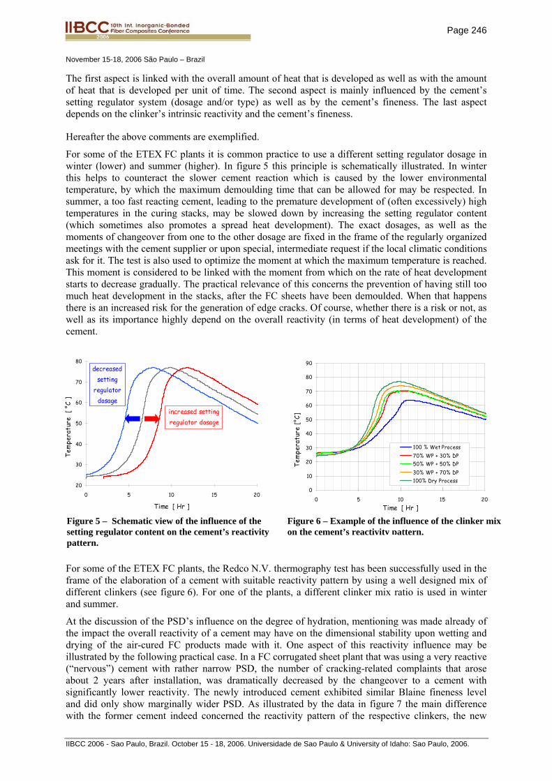
The first aspect is linked with the overall amount of heat that is developed as well as with the amount of heat that is developed per unit of time. The second aspect is mainly influenced by the cement’s setting regulator system (dosage and/or type) as well as by the cement’s fineness. The last aspect depends on the clinker’s intrinsic reactivity and the cement’s fineness.
Hereafter the above comments are exemplified.
For some of the ETEX FC plants it is common practice to use a different setting regulator dosage in winter (lower) and summer (higher). In figure 5 this principle is schematically illustrated. In winter this helps to counteract the slower cement reaction which is caused by the lower environmental temperature, by which the maximum demoulding time that can be allowed for may be respected. In summer, a too fast reacting cement, leading to the premature development of (often excessively) high temperatures in the curing stacks, may be slowed down by increasing the setting regulator content (which sometimes also promotes a spread heat development). The exact dosages, as well as the moments of changeover from one to the other dosage are fixed in the frame of the regularly organized meetings with the cement supplier or upon special, intermediate request if the local climatic conditions ask for it. The test is also used to optimize the moment at which the maximum temperature is reached. This moment is considered to be linked with the moment from which on the rate of heat development starts to decrease gradually. The practical relevance of this concerns the prevention of having still too much heat development in the stacks, after the FC sheets have been demoulded. When that happens there is an increased risk for the generation of edge cracks. Of course, whether there is a risk or not, as well as its importance highly depend on the overall reactivity (in terms of heat development) of the cement.
For some of the ETEX FC plants, the Redco N.V. thermography test has been successfully used in the frame of the elaboration of a cement with suitable reactivity pattern by using a well designed mix of different clinkers (see figure 6). For one of the plants, a different clinker mix ratio is used in winter and summer.
At the discussion of the PSD’s influence on the degree of hydration, mentioning was made already of the impact the overall reactivity of a cement may have on the dimensional stability upon wetting and drying of the air-cured FC products made with it. One aspect of this reactivity influence may be illustrated by the following practical case. In a FC corrugated sheet plant that was using a very reactive (“nervous”) cement with rather narrow PSD, the number of cracking-related complaints that arose about 2 years after installation, was dramatically decreased by the changeover to a cement with significantly lower reactivity. The newly introduced cement exhibited similar Blaine fineness level and did only show marginally wider PSD. As illustrated by the data in figure 7 the main difference with the former cement indeed concerned the reactivity pattern of the respective clinkers, the new
20
30
40
50
60
70
80
0 5 10 15 20
Time [ Hr ]
increased setting regulator dosage
decreased setting
regulator dosage
Tem
pera
ture
[ °
C ]
0
10
20
30
40
50
60
70
80
90
0 5 10 15 20Time [ Hr ]
100 % Wet Process70% WP + 30% DP50% WP + 50% DP30% WP + 70% DP100% Dry Process
Tem
pera
ture
[°C]
Figure 5 – Schematic view of the influence of the setting regulator content on the cement’s reactivity pattern.
Figure 6 – Example of the influence of the clinker mix on the cement’s reactivity pattern.

Page 247
November 15-18, 2006 São Paulo – Brazil
IIBCC 2006 - Sao Paulo, Brazil. October 15 - 18, 2006. Universidade de Sao Paulo & University of Idaho: Sao Paulo, 2006.
cement being based on a lazier but after all still sufficiently reactive clinker. The final decision on the changeover to the alternative cement was mainly taken on the basis of the much better behaviour of corrugated sheets made with it in the so-called “free bowing test”. In this test, full width but only 30 cm long corrugated sheet samples are positioned on two supports without fixation, and continuously humidified on the upper surface by means of sprayers, while the lower surface is not. Moreover, for this test, the lower sheet surface is coated in order to avoid any moistening via that surface. The deformation of the sample upon the one-sided moistening is registered in time. As is shown in figure 7 it turned out that the sheets made with the alternative cement exhibited significantly lower deformation. By that, significantly lower tensions are built up when the deformation is hindered by the sheet’s fixation as is the case in its real life application. This difference in dimensional behaviour is believed to be due to the different reaction kinetics and the overall reactivity level obtained in the final sheet. It may be that, via the different degree of pre-hydration of the cement particles at the time of the FC sheet formation, a difference in the intrinsic clinker reaction kinetics, irrespective of the setting regulator’s working, also influences the particle packing. Therefore, it is very likely that part of the observed differences in deformation behaviour is due to differences in particle packing too.
““SSPPEECCIIFFIICCAATTIIOONN””
The thermography test does not lead to one or the other quantitative specification for a cement’s reactivity pattern. As can be learned from the examples, the test is used in a rather qualitative way to get a first indication of the reactivity pattern of a new cement as well as to fine-tune the reactivity profile of a cement in view of the specific requirements of the Hatschek production line(s) for which it is intended. The latter process always evolves in close collaboration with the FC plant production people and of course the cement plant. Last but not least, it is remarked that the standard Redco N.V.
Figure 7 – View of the free bowing test setup, the different bowing behaviour, the granulometric and fineness data of both cements and their resepctive reactivity patterns.
bulging
0
5
10
15
20
25
30
35
40
0:00 0:30 1:00 1:30 2:00 2:30
Time since start of test [Hr:min]
Bulg
ing
[mm
]
Present cement
Former cement
Free bowing upon one-side wetting
0.0
0.5
1.0
1.5
2.0
2.5
3.0
3.5
4.0
4.5
0.1 1 10 100 1000
Interval-center [ um ]
Volu
me-
% p
arti
cles
in s
ize
clas
s
Width of interval [ um ] = 0.091 * interval-center [ um ]
Former cementBlaine: 3040 cm2/gRRSB-parameters: - slope n: 1.13 - pos.par. X': 22.8 µm
Present cementBlaine: 3130 cm2/gRRSB-parameters: - slope n: 1.12 - pos.par. X': 25.2 µm
PSD - Differential presentation -
20
30
40
50
60
70
80
90
0 5 10 15 20 25
Time [ Hr ]
Tem
pera
ture
[ °
C ]
Reactivity patterns as measured by Redco Thermography Test
Former cementBlaine: 3040 cm2/gC3A: 9.9 M-%
Present cementBlaine: 3130 cm2/gC3A: 0.8 M-%
Page 248
November 15-18, 2006 São Paulo – Brazil
IIBCC 2006 - Sao Paulo, Brazil. October 15 - 18, 2006. Universidade de Sao Paulo & University of Idaho: Sao Paulo, 2006.
thermography test does not take into account industrial conditions such as the process water’s dissolved salts and organics content and temperature. Additionally it is executed on cement-water paste and not on the complete FC mixture. So, the final adjustments always have to be made by means of close observation of the temperature evolution in the stacks in real production environment.
4. CONDENSED SILICA FUME FOR HATSCHEK-BASED FC PRODUCTS
4.1. Introduction
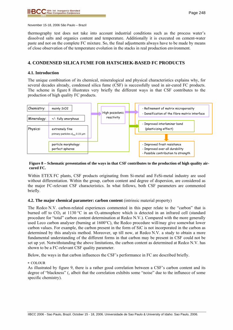
The unique combination of its chemical, mineralogical and physical characteristics explains why, for several decades already, condensed silica fume (CSF) is successfully used in air-cured FC products. The scheme in figure 8 illustrates very briefly the different ways in that CSF contributes to the production of high quality FC products.
Within ETEX FC plants, CSF products originating from Si-metal and FeSi-metal industry are used without differentiation. Within the group, carbon content and degree of dispersion, are considered as the major FC-relevant CSF characteristics. In what follows, both CSF parameters are commented briefly.
4.2. The major chemical parameter: carbon content (intrinsic material property)
The Redco N.V. carbon-related experiences commented in this paper relate to the “carbon” that is burned off to CO2 at 1130 °C in an O2-atmosphere which is detected in an infrared cell (standard procedure for “total” carbon content determination at Redco N.V.). Compared with the more generally used Leco carbon analyser (burning at 1600°C), the Redco procedure will/may give somewhat lower carbon values. For example, the carbon present in the form of SiC is not incorporated in the carbon as determined by this analysis method. Moreover, up till now, at Redco N.V. a study to obtain a more fundamental understanding of the different forms in that carbon may be present in CSF could not be set up yet. Notwithstanding the above limitations, the carbon content as determined at Redco N.V. has shown to be a FC-relevant CSF quality parameter.
Below, the ways in that carbon influences the CSF’s performance in FC are described briefly.
• CCOOLLOOUURR As illustrated by figure 9, there is a rather good correlation between a CSF’s carbon content and its degree of “blackness” (, albeit that the correlation exhibits some “noise” due to the influnece of some specific chemistry).
Chemistry: mainly SiO2 - Refinement of matrix microporosity - Densification of the fibre-matrix interface
Mineralogy: +/- fully amorphous - Improved interlaminar bond
Physics: extremely fine (plasticizing effect)primary particles davg 0.15 µm
particle morphology: - Improved frost resistanceperfect spheres - Improved over-all durability
- Possible contribution to strength
High pozzolanic reactivity
Figure 8 – Schematic presentation of the ways in that CSF contributes to the production of high quality air-cured FC.

Page 249
November 15-18, 2006 São Paulo – Brazil
IIBCC 2006 - Sao Paulo, Brazil. October 15 - 18, 2006. Universidade de Sao Paulo & University of Idaho: Sao Paulo, 2006.
However, the exact effect that the colour of CSF has on the shade of the FC product further depends on the colour effects of the other ingredients (cement, cellulose etc.), the CSF dosage and, most likely, its degree of dispersion. Whether the shade variation of the FC product that is introduced by variations of the CSF carbon content are acceptable or not, of course also depends on the fact whether the final FC product is coated or not.
Carbon may also lead to a black spotted FC surface in case the CSF (and by that the carbon present in it) is not well dispersed, or in (the nowadays very exceptional) case it contains relatively coarse coal particles. Even for coated FC products such black spots or stripes are undesirable since they represent spots with no or only very weak cementation (and by that poor paint fixation).
• HHAATTSSCCHHEEKK PPRROOCCEESSSS In some cases carbon from CSF is also suspected of disturbing the Hatschek process in more than one way.
One possible problem reveals as an extreme dirtying of the process water usually in combination with a premature clogging of the felt. Within ETEX, such clearly CSF-linked dirtying has been reported only few times, and most of the times in one and the same plant, more especially the only ETEX plant producing FC pipes, i.e. FC products with significantly higher CSF content than the standard FC sheet and board products. It could be proved that CSF slurries that gave cause to the above described process problem, next to increased carbon content also exhibited clearly finer PSD. Possibly these two characteristics were not independent from one another, i.e. the problematic CSF slurries possibly contained some extremely fine carbon.
In the end it is assumed that the appearance of this type of problem is linked with the occurrence of a “harmful” combination of the CSF’s carbon content, the presence of (a) certain type(s) of carbon and the CSF dosage in the FC formulation. Whether a problem will occur or not, is most probably also influenced by the very Hatschek production line considered (f.e. the backwater cleaning system). Additionally it is assumed that a disturbance of the flocculation mechanism by (some fraction of ?) the carbon is at the basis of the process problems.
Another CSF-induced Hatschek process problem that may occur, reveals the extreme dirtying of the forming drum by a sticky, black deposit in such a way that no sheet can be formed anymore since the fresh FC layers continuously fall down from the drum. Again, it has not been possible to study this problem in a parametric way. So, a scientifically based explanation for the problem could not be elaborated. Though, based on the observations made, it is believed that this extreme pollution of the forming drum is most probably linked with the presence of a too important content of very coarse (say > 45 - 150 µm), carbon rich particles and/or agglomerates in the CSF. As the prior problem it has only be observed for CSF slurry products.
““SSPPEECCIIFFIICCAATTIIOONN””
In view of minimizing the risk for the above described potential problems, within ETEX, preference has always been given to CSF products with (as) low carbon content (as possible). This ambition is
30
35
40
45
50
0,6 1,0 1,4 1,8
% Carbon
% r
efle
ctan
ce
dark
er
Erichsen Model 527 Tint Tester
Light source
Light sensor
Filter
45°
0°Sample
Figure 9 – Correlation between degree of darkness of a CSF and its carbon content. [Data obtained from Elkem Materials Ltd. - ]
Page 250
November 15-18, 2006 São Paulo – Brazil
IIBCC 2006 - Sao Paulo, Brazil. October 15 - 18, 2006. Universidade de Sao Paulo & University of Idaho: Sao Paulo, 2006.
incorporated in the technical specifications, in terms of the maximum allowable carbon content. Based on practical experience, a maximum limit of 2.0 M-% is considered as a safe solution, albeit that the choice of the exact value was not made on a real parametric study. Further this requirement is accompanied by a specification for the loss on ignition (1 Hr at 1000° C): LOI ≤ 2.5 M-%. Of course, LOI and carbon content are interdependent parameters, their exact relation being dependent on the very CSF source considered. Practical experience showed that in most cases, the above LOI requirement is less severe than the carbon limit.
Nowadays, due to the CSF supply difficulties, the specifications on carbon and LOI sometimes have to be slightly violated. It is tried to absorb this inconvenience by dedicating such “out of spec” CSF to well-selected FC plant(s). The identification of those FC plants depends in the first place on the type(s) of FC products made there and in the second place on logistical parameters. Up till now, this controlled use of CSF of which Ctotal is (moderately) above 2.0 M-% did neither cause process problems, nor quality problems with the finished FC product.
The European standard EN 13263-1, elaborated for the application of CSF in concrete, only holds a specification limit for LOI1000 °C and not for carbon: LOI1000 °C ≤ 4.0 M-%. Though, we consider this value to be too high for being used as a general specification for all FC products,.
4.3. The major physical parameter: degree of dispersion (property of the home-made or purchased CSF preparation)
The scheme in figure 8 clearly indicates that a sufficiently fine dispersion and a homogeneous distribution of the CSF throughout the matrix phase is of the utmost importance. Firstly the absence of “big” agglomerates in the FC product has to be guaranteed, secondly the homogeneous distribution of the CSF throughout the matrix (ideally down till the smallest possible scale, i.e. that of the primary CSF particle) has to be realized.
• The need for the avoidance of big agglomerates.
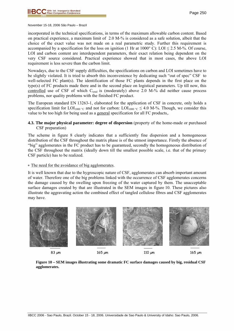
It is well known that due to the hygroscopic nature of CSF, agglomerates can absorb important amount of water. Therefore one of the big problems linked with the occurrence of CSF agglomerates concerns the damage caused by the swelling upon freezing of the water captured by them. The unacceptable surface damages created by that are illustrated in the SEM images in figure 10. These pictures also illustrate the aggravating action the combined effect of tangled cellulose fibres and CSF agglomerates may have.
83 µm 165 µm 110 µm 165 µm
Figure 10 – SEM images illustrating some dramatic FC surface damages caused by big, residual CSF agglomerates.

Page 251
November 15-18, 2006 São Paulo – Brazil
IIBCC 2006 - Sao Paulo, Brazil. October 15 - 18, 2006. Universidade de Sao Paulo & University of Idaho: Sao Paulo, 2006.
It has been observed that potassium ions which are abundantly present in the FC matrix exhibit a preferential migration towards such amorphous silica concentrations. In figure 11 a clear illustration of that is given.
This observation triggered off the question as whether certain CSF agglomerates might cause problems similar to that created by the (retarded) reaction between alkalis and certain forms of silica in the aggregates of concrete, well-known as alkali-silica-reaction, i.e. ASR. Although we did not make an experimental study of the topic we assume that such retarded ASR on its own, is not likely to hold a major durability risk since potential swelling of the CSF agglomerates due to water absorbing ASR gel is believed to be easily absorbed by the high (and big sized) porosity of FC. However, for CSF agglomerates at, or close to the FC product’s surface the situation may be more critical. Further it cannot be excluded that the presence of water absorbing ASR gel has a indirect detrimental action via congelation.
• The need for fine dispersion and homogeneous distribution.
For one and the same CSF dosage, increased degree of dispersion means increased number of “ball bearings” in the fresh FC layer and increased CSF surface available for pozzolanic reaction. The higher amount of (early) reaction gel (present as “soft blankets” on the CSF particles) will highly contribute to the plasticity generated by the CSF. Higher degree of dispersion also improves the availability of the CSF throughout the FC matrix by which the durability enhancing effect of the CSF is promoted.
““SSPPEECCIIFFIICCAATTIIOONN””
Although the above considerations on the need for good CSF dispersion are obvious, the way in that “good dispersion” has to be evaluated and specified is far from clear! The first question concerns the way in that a CSF’s degree of dispersion can be reliably measured. The second question concerns the definition of the minimum degree of dispersion that is needed and the maximum size of CSF agglomerates that still can be allowed for.
“Degree of dispersion” refers to what extent the primary CSF particles are separated from one another. Therefore the most obvious parameter to measure the degree of dispersion of a CSF preparation is its particle size distribution (PSD). However, other parameters such as for example the viscosity of the preparation, taking into account also the preparation’s solids content, might also be used to elaborate a practical measure for degree of dispersion.
Mapping for
Ca Fe
Al Si K
33 µm
Figure 11 – SEM image of a hard CSF agglomerate in a FC matrix (left) and the corresponding mapping patterns for Al, Si, K, Ca and Fe.
Page 252
November 15-18, 2006 São Paulo – Brazil
IIBCC 2006 - Sao Paulo, Brazil. October 15 - 18, 2006. Universidade de Sao Paulo & University of Idaho: Sao Paulo, 2006.
Anyhow, at Redco N.V., the overall degree of dispersion is evaluated by means of laser beam diffraction based PSD measurement, whereas the amount (and size) of coarse agglomerates is evaluated by means of (cumulative) 45 µm (and 75 µm and 150 µm) sieve residue. A detailed description of the respective measurement procedures falls beyond the scope of this paper.
None of these two methods can be claimed as being an ideal and absolute evaluation tool. The results of these tests always have to be carefully interpreted, taking into account additional information on the CSF product under study.
For commercially available, chemically stabilized, “fresh” powder based CSF slurries, the measurement of their PSD is complicated by the flocculation of their particles in the measurement liquid. Though, their overall degree of dispersion is considered as largely sufficient for FC.
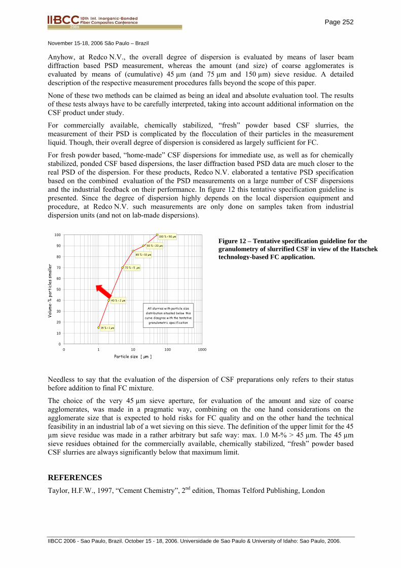
For fresh powder based, “home-made” CSF dispersions for immediate use, as well as for chemically stabilized, ponded CSF based dispersions, the laser diffraction based PSD data are much closer to the real PSD of the dispersion. For these products, Redco N.V. elaborated a tentative PSD specification based on the combined evaluation of the PSD measurements on a large number of CSF dispersions and the industrial feedback on their performance. In figure 12 this tentative specification guideline is presented. Since the degree of dispersion highly depends on the local dispersion equipment and procedure, at Redco N.V. such measurements are only done on samples taken from industrial dispersion units (and not on lab-made dispersions).
Needless to say that the evaluation of the dispersion of CSF preparations only refers to their status before addition to final FC mixture.
The choice of the very 45 µm sieve aperture, for evaluation of the amount and size of coarse agglomerates, was made in a pragmatic way, combining on the one hand considerations on the agglomerate size that is expected to hold risks for FC quality and on the other hand the technical feasibility in an industrial lab of a wet sieving on this sieve. The definition of the upper limit for the 45 µm sieve residue was made in a rather arbitrary but safe way: max. 1.0 M-% > 45 µm. The 45 µm sieve residues obtained for the commercially available, chemically stabilized, “fresh” powder based CSF slurries are always significantly below that maximum limit.
REFERENCES Taylor, H.F.W., 1997, “Cement Chemistry”, 2nd edition, Thomas Telford Publishing, London
Figure 12 – Tentative specification guideline for the granulometry of slurrified CSF in view of the Hatschek technology-based FC application.
15 % < 1 µm
40 % < 2 µm
70 % < 5 µm
85 % < 10 µm
90 % < 20 µm
100 % < 50 µm
0
10
20
30
40
50
60
70
80
90
100
0 1 10 100 1000
Particle size [ µm ]
Volu
me-
% p
arti
cles
sm
alle
r
All slurries w ith particle size distribution situated below this
curve disagree w ith the tentative granulometric specification