Embed Size (px)
Citation preview
Malaysian Journal of Analytical Sciences, Vol 21 No 2 (2017): 323 - 333
DOI: https://doi.org/10.17576/mjas-2017-2102-07
323
MALAYSIAN JOURNAL OF ANALYTICAL SCIENCES
Published by The Malaysian Analytical Sciences Society
THE SYNTHESIS OF ZINC OXIDE/CARBON SPHERES
NANOCOMPOSITES AND FIELD ELECTRON EMISSION PROPERTIES
(Sintesis Nanokomposit Zink Oksida/Sfera Karbon dan Sifat Pemancaran Elektron Medan)
Suriani Abu Bakar1,2
*, Suhufa Alfarisa1,2,3
, Azmi Mohamed1,4
, Norhayati Hashim1,4
1Nanotechnology Research Centre, Faculty of Science and Mathematics
2Department of Physics, Faculty of Science and Mathematics
Universiti Pendidikan Sultan Idris, 35900 Tanjung Malim, Perak, Malaysia 3Department of Physics, Faculty of Mathematics and Natural Science,
Universitas PGRI Palembang, Jl. Jend Ahmad Yani 9/10 Ulu, Palembang 30251, South Sumatera, Indonesia 4Department of Chemistry, Faculty of Science and Mathematics,
Universiti Pendidikan Sultan Idris, 35900 Tanjung Malim, Perak, Malaysia
*Corresponding author: [email protected]
Received: 19 November 2016; Accepted: 6 March 2017
Abstract
Zinc oxide (ZnO)/carbon spheres (CS) nanocomposites were successfully synthesised using waste engine oil as precursor for the
CS production. ZnO nanorods were grown using sol-gel immersion method with MgZnO as the seeded catalyst and thermal
chemical vapour deposition was used to synthesise CS. Different configurations of ZnO/CS structures were prepared i.e. CS-
coated ZnO and ZnO-coated CS. The structures of composite samples were analysed using field emission scanning electron
microscopy (FESEM), Energy-Dispersive X-ray (EDX), micro-Raman and X-ray Diffraction Spectroscopy (XRD). FESEM
observations revealed the structural changes of pristine ZnO and CS in composite structures. The as-present of ZnO or CS was
believed to affect the subsequent growth of another structure. Field electron emission (FEE) properties of both nanocomposites
were also investigated. It was found that ZnO-coated CS sample has better FEE properties with lower turn-on (3.48 Vµm-1) and
threshold field (6.35 Vµm-1) obtained at current density of 0.1 and 1 µAcm-2, respectively. This study highlighted that
nanocomposites of ZnO and CS have successfully enhanced the field emission performances of materials compared with pristine
ZnO or CS due to the structural changes of material emitter.
Keywords: zinc oxide, carbon spheres, waste engine oil, field electron emission
Abstrak
Nanokomposit zink oksida (ZnO)/sfera karbon (SK) telah berjaya disintesis menggunakan minyak enjin terpakai sebagai pelopor
untuk penghasilan SK. Nanorod ZnO telah ditumbuhkan menggunakan kaedah rendaman sol-gel dengan MgZnO sebagai
pemangkin berbenih dan pemendapan wap kimia terma telah digunakan untuk mensintesis SK. Konfigurasi yang berlainan bagi
struktur ZnO/SK telah disediakan iaitu SK bersalut ZnO dan ZnO bersalut SK. Struktur sampel komposit dianalisis
menggunakan Mikroskop Imbasan Elektron Pancaran Medan (FESEM), penyerakan tenaga sinar-X (EDX), spektroskopi mikro-
Raman dan pembelauan sinar-X (XRD). Pemerhatian FESEM menunjukkan perubahan struktur ZnO dan CS tulen dalam
struktur komposit. ZnO atau CS sedia ada dipercayai memberi kesan kepada pertumbuhan seterusnya struktur lain. Sifat
pemancaran elektron medan (PEM) bagi kedua-dua nanokomposit juga turut dikaji. Kajian mendapati bahawa sampel ZnO
bersalut SK mempunyai ciri-ciri PEM yang lebih baik dengan nilai medan permulaan (3.48 Vμm-1) dan ambang (6.35 Vμm-1)
yang lebih rendah diperolehi pada ketumpatan arus 0.1 dan 1 μAcm-2. Kajian ini menekankan nanokomposit ZnO dan SK telah
berjaya meningkatkan prestasi pemancaran medan bahan berbanding dengan ZnO atau CS tulen disebabkan oleh perubahan
struktur bahan pemancar.
ISSN
1394 - 2506
Suriani et al: THE SYNTHESIS OF ZINC OXIDE/CARBON SPHERES NANOCOMPOSITES AND FIELD
ELECTRON EMISSION PROPERTIES
324
Kata kunci: zink oksida, sfera karbon, minyak enjin terpakai, pemancaran elektron medan
Introduction
Field emission is a quantum process of electron emission from a material where the electrons in Fermi level tunnel
the energy barrier to vacuum level under high applied electric field [1]. Emission characteristics of a material are
based on the Fowler-Nordheim (F-N) theory as followed in Eq. 1 [2]:
𝐽 =𝐴(𝛽𝐸)
𝜑
2
𝑒𝑥𝑝 (𝐵𝜑
32⁄
𝛽𝐸) (1)
The current emission density (J) at applied electric field (E) can be calculated from the above equation. A and B are
constants of 1.54 x 10⁻⁶
AV-2
eV and 6.83 x 10⁹ eV
-3/2Vm
-1, respectively. Field enhancement factor of emitter () is
an important FEE characteristic and can be calculated from the slope of ln (J/E2) vs 1/E curve using the equation =
-B3/2
/slope. A typical benchmark that have been reported in the literature for FEE characterization comparison are
the turn-on and threshold field, maximum current obtained (before the destruction of the emitter) as well as
emission stability. Turn-on field for FEE is the field required to emit current density which is greater than the
electrical noise-floor [3]. There is no agreement on the value of current density to be specified and the definition of
turn-on and threshold field, it is determined by the group research themselves. For example, Ghosh et al. [4, 5] and
Srivastava et al. [6] defined turn-on and threshold field to be the field required by the film to produce current
density of 10 µAcm-2
and 1 mAcm-2
respectively. While Bonard and co-worker [90] specified the current density of
10 µAcm-2
and 10 mAcm-2
respectively. Since there is no specific definition of both turn-on and threshold field and
as current density does not increase linearly with applied field, the result cannot be accurately compared. The
comparisons between the results were only a rough estimation to claim that theirs is better than others. In this
study, they are defined as the current density at applied field of 0.1 and 1 µAcm-2
, respectively for turn-on and
threshold field.
To increase the FEE performance of the materials, it can be composited to further enhance the electron emission
performance of those nanocomposites. Take carbon material such as carbon nanotubes (CNTs) as example, in view
of its potential application as good electron emitters, however it can be easily degraded and damaged by the
following factors [7-10], therefore the improvement of the FEE can be achieved by fabricating CNTs and zinc-oxide
(ZnO) as nanocomposites [11-13]. The order of the configuration of CNTs/ZnO composites is the crucial
component that lead to the enhancement of field emission ability, where it frequently occurs that the materials
fabricated at the top is more likely to help the FEE performances. ZnO/CNTs nanocomposites structure have been
reported to improve the FEE performance of material [1, 11-14]. In our recently published work [11], the
investigation was done on the composite configuration to enhance the FEE performance by using two different
configurations of ZnO/vertically aligned CNTs (VACNTs) where the order of the nanocomposites plays an
important role in improving the FEE properties of pristine VACNTs.
The work revealed that the VACNTs-coated ZnO nanocomposites configuration showed a lower turn-on and
threshold field at only 0.49 and 1.41 Vµm-1
as compared to the ZnO-coated VACNTs of 1.60 (turn-on) and 2.03
(threshold field) Vµm-1
respectively. The presence of different ZnO nanostructures including nanorods, nanoflowers
and nanorods-nanoflakes for ZnO-coated CNTs configuration were seen to play significant role towards enhancing
FEE performances [13]. Among the ZnO nanostructured used the growth of CNTs on ZnO nanoflower
demonstrated the highest FEE performance of 0.8 Vµm-1
at 1 uAcm-2
of turn-on field. ZnO is a semiconducting
material with wide direct band gap (3.37 eV), large binding energy of 60 meV and and work function of 5.3 eV [1].
It has been applied in many electronic devices due to its unique and versatile properties [15-17]. ZnO nanostructures
also showed promising application in field emission devices due to its high mechanical strength, chemical stability
and good optical properties [18, 19]. On the other hand, carbon materials are well known as a conducting material
which is good for electron emission application. One type of carbon materials namely carbon spheres (CS) has been
reported to have a comparable field emission properties as compared to other materials [20].
Malaysian Journal of Analytical Sciences, Vol 21 No 2 (2017): 323 - 333
DOI: https://doi.org/10.17576/mjas-2017-2102-07
325
Here we presented the composite structures of ZnO/CS and their FEE properties. To the best of our knowledge, this
is the first report on the FEE of the CS synthesised from waste engine oil (WEO) with two different configurations
of nanocomposite; CS-coated aligned ZnO nanorod and ZnO nanorod-coated CS sample. Recently, we reported the
use of WEO for the production of another carbon material namely CNTs [21] and amorphous Al-Cu alloy
nanowires decorated with CS [22]. The use of waste [23-27] and natural precursors [28-36] to produce carbon
materials may not only be beneficial for nanotechnology research field but also preserve the environmental
sustainability at the same time. The CS were synthesised using thermal chemical vapour deposition (TCVD) method
while the ZnO were synthesised using the sol-gel method. The structural and field emission properties of ZnO/CS
nanocomposites samples were then systematically investigated.
Materials and Methods
The production of ZnO/CS was performed in two different synthesis processes which were (i) the synthesis of ZnO
nanorods using sol-gel immersion process and (ii) the synthesis of CS via thermal chemical vapour deposition
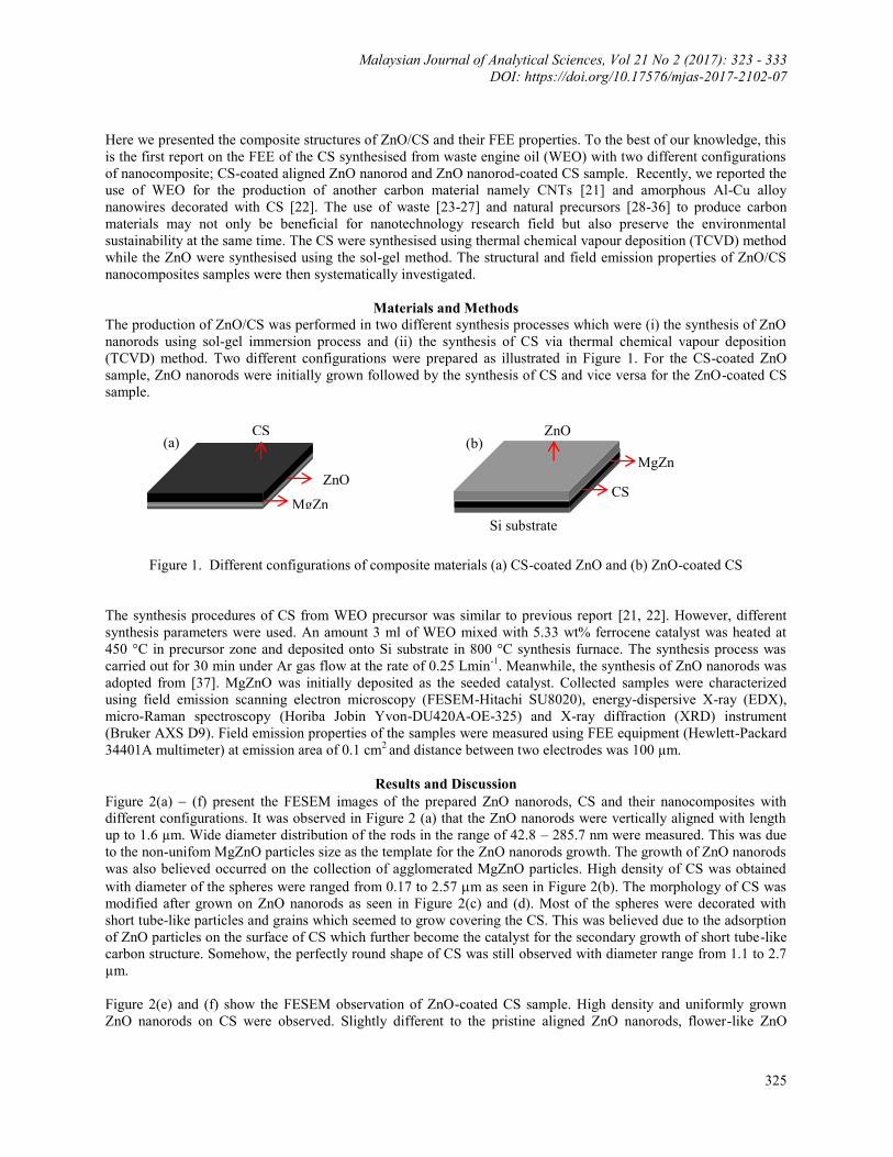
(TCVD) method. Two different configurations were prepared as illustrated in Figure 1. For the CS-coated ZnO
sample, ZnO nanorods were initially grown followed by the synthesis of CS and vice versa for the ZnO-coated CS
sample.
Figure 1. Different configurations of composite materials (a) CS-coated ZnO and (b) ZnO-coated CS
The synthesis procedures of CS from WEO precursor was similar to previous report [21, 22]. However, different
synthesis parameters were used. An amount 3 ml of WEO mixed with 5.33 wt% ferrocene catalyst was heated at
450 °C in precursor zone and deposited onto Si substrate in 800 °C synthesis furnace. The synthesis process was
carried out for 30 min under Ar gas flow at the rate of 0.25 Lmin-1
. Meanwhile, the synthesis of ZnO nanorods was
adopted from [37]. MgZnO was initially deposited as the seeded catalyst. Collected samples were characterized
using field emission scanning electron microscopy (FESEM-Hitachi SU8020), energy-dispersive X-ray (EDX),
micro-Raman spectroscopy (Horiba Jobin Yvon-DU420A-OE-325) and X-ray diffraction (XRD) instrument
(Bruker AXS D9). Field emission properties of the samples were measured using FEE equipment (Hewlett-Packard
34401A multimeter) at emission area of 0.1 cm2 and distance between two electrodes was 100 µm.
Results and Discussion
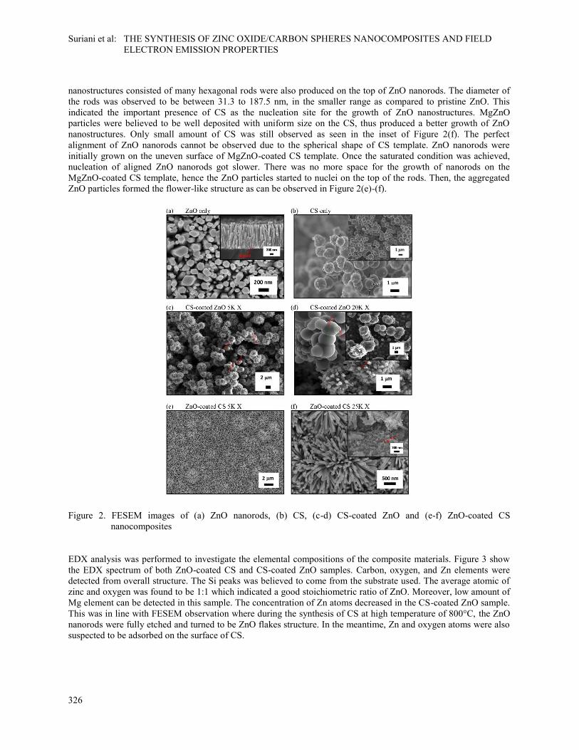
Figure 2(a) (f) present the FESEM images of the prepared ZnO nanorods, CS and their nanocomposites with
different configurations. It was observed in Figure 2 (a) that the ZnO nanorods were vertically aligned with length
up to 1.6 µm. Wide diameter distribution of the rods in the range of 42.8 – 285.7 nm were measured. This was due
to the non-unifom MgZnO particles size as the template for the ZnO nanorods growth. The growth of ZnO nanorods
was also believed occurred on the collection of agglomerated MgZnO particles. High density of CS was obtained
with diameter of the spheres were ranged from 0.17 to 2.57 m as seen in Figure 2(b). The morphology of CS was
modified after grown on ZnO nanorods as seen in Figure 2(c) and (d). Most of the spheres were decorated with
short tube-like particles and grains which seemed to grow covering the CS. This was believed due to the adsorption
of ZnO particles on the surface of CS which further become the catalyst for the secondary growth of short tube-like
carbon structure. Somehow, the perfectly round shape of CS was still observed with diameter range from 1.1 to 2.7
µm.
Figure 2(e) and (f) show the FESEM observation of ZnO-coated CS sample. High density and uniformly grown
ZnO nanorods on CS were observed. Slightly different to the pristine aligned ZnO nanorods, flower-like ZnO
CS
CS ZnO
Si substrate
MgZn
O
ZnO
MgZn
O
(a) (b)
Suriani et al: THE SYNTHESIS OF ZINC OXIDE/CARBON SPHERES NANOCOMPOSITES AND FIELD
ELECTRON EMISSION PROPERTIES
326
nanostructures consisted of many hexagonal rods were also produced on the top of ZnO nanorods. The diameter of
the rods was observed to be between 31.3 to 187.5 nm, in the smaller range as compared to pristine ZnO. This
indicated the important presence of CS as the nucleation site for the growth of ZnO nanostructures. MgZnO
particles were believed to be well deposited with uniform size on the CS, thus produced a better growth of ZnO
nanostructures. Only small amount of CS was still observed as seen in the inset of Figure 2(f). The perfect
alignment of ZnO nanorods cannot be observed due to the spherical shape of CS template. ZnO nanorods were
initially grown on the uneven surface of MgZnO-coated CS template. Once the saturated condition was achieved,
nucleation of aligned ZnO nanorods got slower. There was no more space for the growth of nanorods on the
MgZnO-coated CS template, hence the ZnO particles started to nuclei on the top of the rods. Then, the aggregated
ZnO particles formed the flower-like structure as can be observed in Figure 2(e)-(f).
Figure 2. FESEM images of (a) ZnO nanorods, (b) CS, (c-d) CS-coated ZnO and (e-f) ZnO-coated CS
nanocomposites
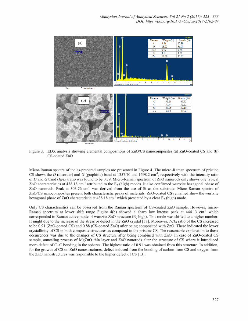
EDX analysis was performed to investigate the elemental compositions of the composite materials. Figure 3 show
the EDX spectrum of both ZnO-coated CS and CS-coated ZnO samples. Carbon, oxygen, and Zn elements were
detected from overall structure. The Si peaks was believed to come from the substrate used. The average atomic of
zinc and oxygen was found to be 1:1 which indicated a good stoichiometric ratio of ZnO. Moreover, low amount of
Mg element can be detected in this sample. The concentration of Zn atoms decreased in the CS-coated ZnO sample.
This was in line with FESEM observation where during the synthesis of CS at high temperature of 800°C, the ZnO
nanorods were fully etched and turned to be ZnO flakes structure. In the meantime, Zn and oxygen atoms were also
suspected to be adsorbed on the surface of CS.
Malaysian Journal of Analytical Sciences, Vol 21 No 2 (2017): 323 - 333
DOI: https://doi.org/10.17576/mjas-2017-2102-07
327
Figure 3. EDX analysis showing elemental compositions of ZnO/CS nanocomposites (a) ZnO-coated CS and (b)
CS-coated ZnO
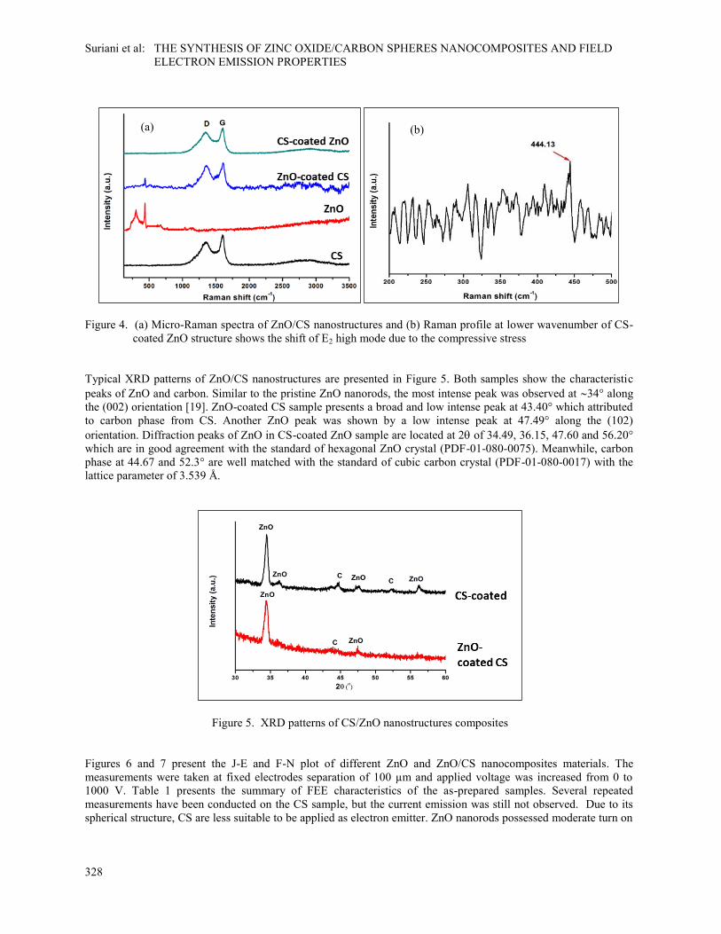
Micro-Raman spectra of the as-prepared samples are presented in Figure 4. The micro-Raman spectrum of pristine
CS shows the D (disorder) and G (graphitic) band at 1357.70 and 1598.2 cm-1
, respectively with the intensity ratio
of D and G band (ID/IG) ratio was found to be 0.79. Micro-Raman spectrum of ZnO nanorods only shows one typical
ZnO characteristics at 438.18 cm-1
attributed to the E2 (high) modes. It also confirmed wurtzite hexagonal phase of
ZnO nanorods. Peak at 303.76 cm-1
was derived from the use of Si as the substrate. Micro-Raman spectra of
ZnO/CS nanocomposites present both characteristic peaks of materials. ZnO-coated CS remained show the wurtzite
hexagonal phase of ZnO characteristic at 438.18 cm-1
which presented by a clear E2 (high) mode.
Only CS characteristics can be observed from the Raman spectrum of CS-coated ZnO sample. However, micro-
Raman spectrum at lower shift range Figure 4(b) showed a sharp low intense peak at 444.13 cm-1
which
corresponded to Raman active mode of wurtzite ZnO structure (E2 high). This mode was shifted to a higher number.
It might due to the increase of the stress or defect in the ZnO crystal [38]. Moreover, ID/IG ratio of the CS increased
to be 0.91 (ZnO-coated CS) and 0.88 (CS-coated ZnO) after being composited with ZnO. These indicated the lower
crystallinity of CS in both composite structures as compared to the pristine CS. The reasonable explanation to these
occurrences was due to the changes of CS structure after being combined with ZnO. In case of ZnO-coated CS
sample, annealing process of MgZnO thin layer and ZnO nanorods alter the structure of CS where it introduced
more defect of CC bonding in the spheres. The highest ratio of 0.91 was obtained from this structure. In addition,
for the growth of CS on ZnO nanostructures, defect-induced from the bonding of carbon from CS and oxygen from
the ZnO nanostructures was responsible to the higher defect of CS [13].
(a)
(b)
Suriani et al: THE SYNTHESIS OF ZINC OXIDE/CARBON SPHERES NANOCOMPOSITES AND FIELD
ELECTRON EMISSION PROPERTIES
328
Figure 4. (a) Micro-Raman spectra of ZnO/CS nanostructures and (b) Raman profile at lower wavenumber of CS-
coated ZnO structure shows the shift of E2 high mode due to the compressive stress
Typical XRD patterns of ZnO/CS nanostructures are presented in Figure 5. Both samples show the characteristic
peaks of ZnO and carbon. Similar to the pristine ZnO nanorods, the most intense peak was observed at 34° along
the (002) orientation [19]. ZnO-coated CS sample presents a broad and low intense peak at 43.40° which attributed
to carbon phase from CS. Another ZnO peak was shown by a low intense peak at 47.49° along the (102)
orientation. Diffraction peaks of ZnO in CS-coated ZnO sample are located at 2 of 34.49, 36.15, 47.60 and 56.20°
which are in good agreement with the standard of hexagonal ZnO crystal (PDF-01-080-0075). Meanwhile, carbon
phase at 44.67 and 52.3° are well matched with the standard of cubic carbon crystal (PDF-01-080-0017) with the
lattice parameter of 3.539 Å.
Figure 5. XRD patterns of CS/ZnO nanostructures composites
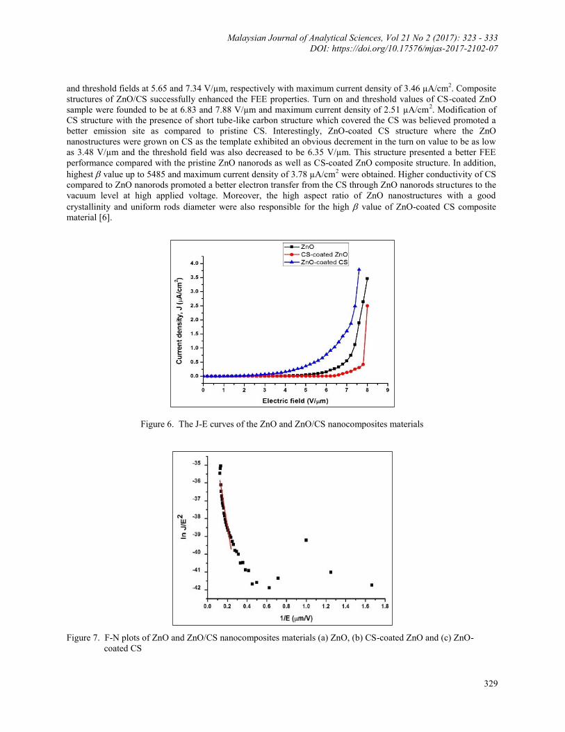
Figures 6 and 7 present the J-E and F-N plot of different ZnO and ZnO/CS nanocomposites materials. The
measurements were taken at fixed electrodes separation of 100 µm and applied voltage was increased from 0 to
1000 V. Table 1 presents the summary of FEE characteristics of the as-prepared samples. Several repeated
measurements have been conducted on the CS sample, but the current emission was still not observed. Due to its
spherical structure, CS are less suitable to be applied as electron emitter. ZnO nanorods possessed moderate turn on
(a) (b)
Malaysian Journal of Analytical Sciences, Vol 21 No 2 (2017): 323 - 333
DOI: https://doi.org/10.17576/mjas-2017-2102-07
329
and threshold fields at 5.65 and 7.34 V/µm, respectively with maximum current density of 3.46 µA/cm2. Composite
structures of ZnO/CS successfully enhanced the FEE properties. Turn on and threshold values of CS-coated ZnO
sample were founded to be at 6.83 and 7.88 V/µm and maximum current density of 2.51 µA/cm2. Modification of
CS structure with the presence of short tube-like carbon structure which covered the CS was believed promoted a
better emission site as compared to pristine CS. Interestingly, ZnO-coated CS structure where the ZnO
nanostructures were grown on CS as the template exhibited an obvious decrement in the turn on value to be as low
as 3.48 V/µm and the threshold field was also decreased to be 6.35 V/µm. This structure presented a better FEE
performance compared with the pristine ZnO nanorods as well as CS-coated ZnO composite structure. In addition,
highest value up to 5485 and maximum current density of 3.78 µA/cm2 were obtained. Higher conductivity of CS
compared to ZnO nanorods promoted a better electron transfer from the CS through ZnO nanorods structures to the
vacuum level at high applied voltage. Moreover, the high aspect ratio of ZnO nanostructures with a good
crystallinity and uniform rods diameter were also responsible for the high value of ZnO-coated CS composite
material [6].
Figure 6. The J-E curves of the ZnO and ZnO/CS nanocomposites materials
Figure 7. F-N plots of ZnO and ZnO/CS nanocomposites materials (a) ZnO, (b) CS-coated ZnO and (c) ZnO-
coated CS
Suriani et al: THE SYNTHESIS OF ZINC OXIDE/CARBON SPHERES NANOCOMPOSITES AND FIELD
ELECTRON EMISSION PROPERTIES
330
Table 1. FEE characteristics of CS, ZnO nanorods and their composite materials
Sample Turn on Field at
0.1 µA (V/µm)
Threshold Field
at 1 µA (V/µm)
J Max
(µA/cm2)
ZnO 5.65 7.34 3.46 2452
ZnO-coated CS 3.48 6.35 3.78 5879
CS-coated ZnO 6.83 7.88 2.51 755
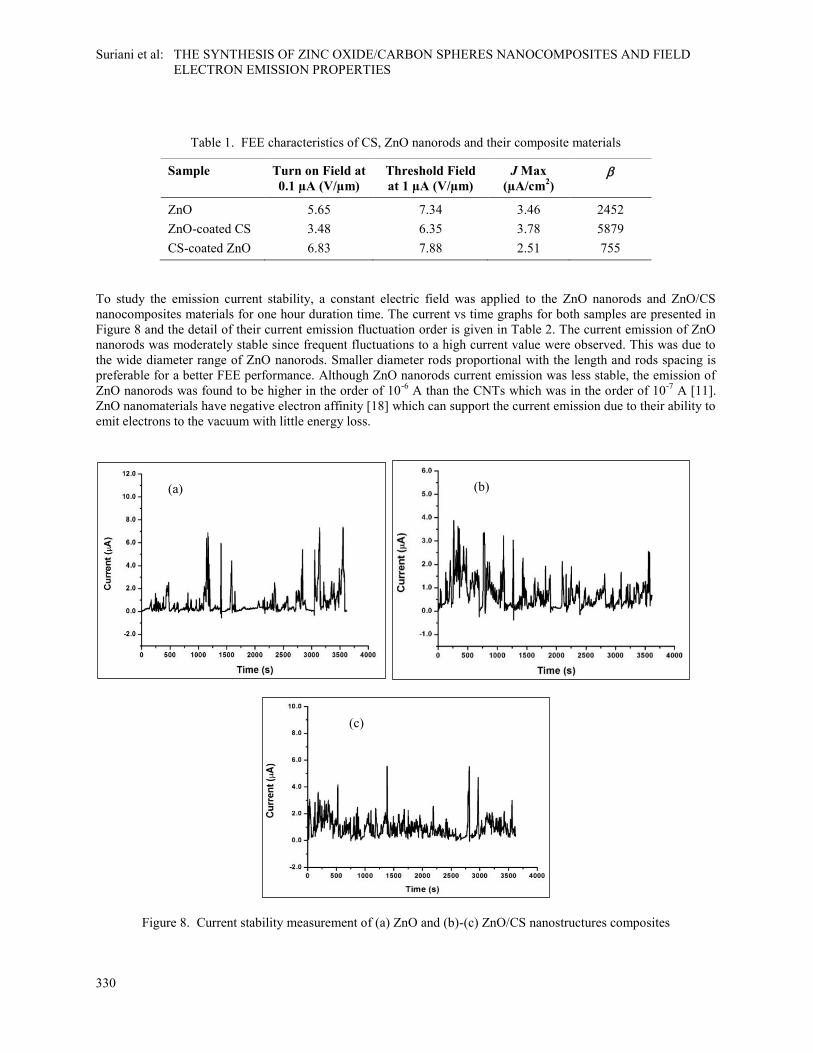
To study the emission current stability, a constant electric field was applied to the ZnO nanorods and ZnO/CS
nanocomposites materials for one hour duration time. The current vs time graphs for both samples are presented in
Figure 8 and the detail of their current emission fluctuation order is given in Table 2. The current emission of ZnO
nanorods was moderately stable since frequent fluctuations to a high current value were observed. This was due to
the wide diameter range of ZnO nanorods. Smaller diameter rods proportional with the length and rods spacing is
preferable for a better FEE performance. Although ZnO nanorods current emission was less stable, the emission of
ZnO nanorods was found to be higher in the order of 10-6
A than the CNTs which was in the order of 10-7
A [11].
ZnO nanomaterials have negative electron affinity [18] which can support the current emission due to their ability to
emit electrons to the vacuum with little energy loss.
Figure 8. Current stability measurement of (a) ZnO and (b)-(c) ZnO/CS nanostructures composites
(b) (a)
(c)
Malaysian Journal of Analytical Sciences, Vol 21 No 2 (2017): 323 - 333
DOI: https://doi.org/10.17576/mjas-2017-2102-07
331
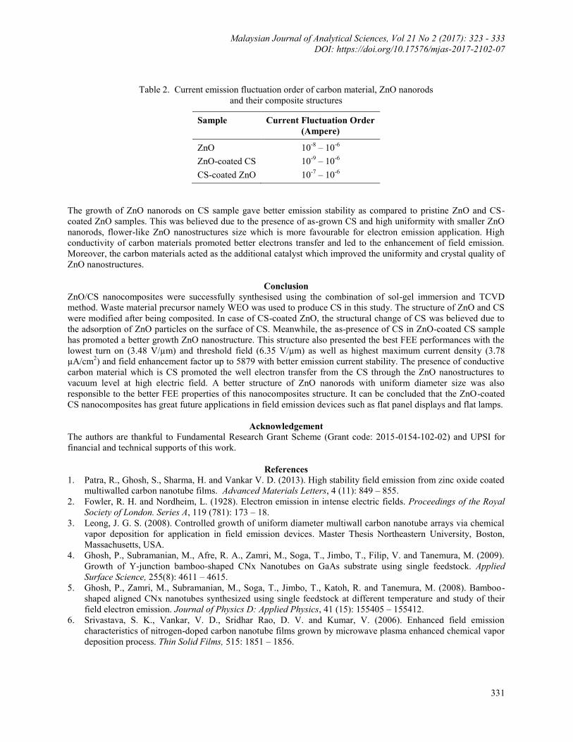
Table 2. Current emission fluctuation order of carbon material, ZnO nanorods
and their composite structures
Sample Current Fluctuation Order
(Ampere)
ZnO 10-8
– 10-6
ZnO-coated CS 10-9
– 10-6
CS-coated ZnO 10-7
– 10-6
The growth of ZnO nanorods on CS sample gave better emission stability as compared to pristine ZnO and CS-
coated ZnO samples. This was believed due to the presence of as-grown CS and high uniformity with smaller ZnO
nanorods, flower-like ZnO nanostructures size which is more favourable for electron emission application. High
conductivity of carbon materials promoted better electrons transfer and led to the enhancement of field emission.
Moreover, the carbon materials acted as the additional catalyst which improved the uniformity and crystal quality of
ZnO nanostructures.
Conclusion
ZnO/CS nanocomposites were successfully synthesised using the combination of sol-gel immersion and TCVD
method. Waste material precursor namely WEO was used to produce CS in this study. The structure of ZnO and CS
were modified after being composited. In case of CS-coated ZnO, the structural change of CS was believed due to
the adsorption of ZnO particles on the surface of CS. Meanwhile, the as-presence of CS in ZnO-coated CS sample
has promoted a better growth ZnO nanostructure. This structure also presented the best FEE performances with the
lowest turn on (3.48 V/µm) and threshold field (6.35 V/µm) as well as highest maximum current density (3.78
µA/cm2) and field enhancement factor up to 5879 with better emission current stability. The presence of conductive
carbon material which is CS promoted the well electron transfer from the CS through the ZnO nanostructures to
vacuum level at high electric field. A better structure of ZnO nanorods with uniform diameter size was also
responsible to the better FEE properties of this nanocomposites structure. It can be concluded that the ZnO-coated
CS nanocomposites has great future applications in field emission devices such as flat panel displays and flat lamps.
Acknowledgement
The authors are thankful to Fundamental Research Grant Scheme (Grant code: 2015-0154-102-02) and UPSI for
financial and technical supports of this work.
References
1. Patra, R., Ghosh, S., Sharma, H. and Vankar V. D. (2013). High stability field emission from zinc oxide coated
multiwalled carbon nanotube films. Advanced Materials Letters, 4 (11): 849 – 855.
2. Fowler, R. H. and Nordheim, L. (1928). Electron emission in intense electric fields. Proceedings of the Royal
Society of London. Series A, 119 (781): 173 – 18.
3. Leong, J. G. S. (2008). Controlled growth of uniform diameter multiwall carbon nanotube arrays via chemical
vapor deposition for application in field emission devices. Master Thesis Northeastern University, Boston,
Massachusetts, USA.
4. Ghosh, P., Subramanian, M., Afre, R. A., Zamri, M., Soga, T., Jimbo, T., Filip, V. and Tanemura, M. (2009).
Growth of Y-junction bamboo-shaped CNx Nanotubes on GaAs substrate using single feedstock. Applied
Surface Science, 255(8): 4611 – 4615.
5. Ghosh, P., Zamri, M., Subramanian, M., Soga, T., Jimbo, T., Katoh, R. and Tanemura, M. (2008). Bamboo-
shaped aligned CNx nanotubes synthesized using single feedstock at different temperature and study of their
field electron emission. Journal of Physics D: Applied Physics, 41 (15): 155405 – 155412.
6. Srivastava, S. K., Vankar, V. D., Sridhar Rao, D. V. and Kumar, V. (2006). Enhanced field emission
characteristics of nitrogen-doped carbon nanotube films grown by microwave plasma enhanced chemical vapor
deposition process. Thin Solid Films, 515: 1851 – 1856.
Suriani et al: THE SYNTHESIS OF ZINC OXIDE/CARBON SPHERES NANOCOMPOSITES AND FIELD
ELECTRON EMISSION PROPERTIES
332
7. Hu, H., Zhang, D., Liu, Y., Yu, W. and Guo, T. (2015). Highly enhanced field emission from CuO nanowire
arrays by coating of carbon nanotube network films. Vacuum, 115: 70 – 74.
8. Yan, X., Tay, B. K. and Miele, P. (2008). Field emission from ordered carbon nanotube-ZnO heterojunction
arrays. Carbon, 46: 753 – 758.
9. Cai, D. and Liu, L. (2013). The screening effects of carbon nanotube arrays and its field emission optimum
density. AIP Advances, 3 (12): 122103.
10. Heo, Y. W., Tien, L. C., Kwon, Y., Norton, D. P., Pearton, S. J., Kang, B. S. and Ren, F. (2004). Depletion-
mode ZnO nanowire field-effect transistor. Applied Physics Letters, 85 (12): 2274 – 2276.
11. Suriani, A. B., Dalila, A. R., Mohamed, A., Mamat, M. H., Malek, M. F., Soga, T. and Tanemura, M. (2016).
Fabrication of vertically aligned carbon nanotubes–zinc oxide nanocomposites and their field electron emission
enhancement. Materials Design, 90: 185 – 195.
12. Suriani, A. B., Safitri, R. N., Mohamed, A., Alfarisa, S., Isa, I. M., Kamari, A., Hashim, N., Ahmad, M. K.,
Malek, M. F. and Rusop M. (2015). Enhanced field electron emission of flower-like zinc oxide on zinc oxide
nanorods grown on carbon nanotubes. Materials Letters, 149: 66 – 69.
13. Suriani, A. B., Safitri, R. N., Mohamed, A., Alfarisa, S., Malek, M. F., Mamat, M. H. and Ahmad M. K. (2016).
Synthesis and field electron emission properties of waste cooking palm oil-based carbon nanotubes coated on
different zinc oxide nanostructures. Journal of Alloys and Compounds, 656: 368 –377.
14. Dutta, M. and Basak, D. (2019). Multiwalled carbon nanotubes/ZnO nanowires composite structure with
enhanced ultraviolet emission and faster ultraviolet response. Chemical Physics Letters, 480(4-6): 253 –257.
15. Flickyngerová, S., Tvarožek, V. and Gašpierik, P. (2010). Zinc oxide - A unique material for advanced
photovoltaic solar cells. Journal of Electrical Engineering, 61(5): 291 – 295.
16. Nohavica, D. and Gladkov. P. (2010). ZnO nanoparticles and their applications-new achievements.
Proceedings of the 2nd
International Conference on Nanotechnology, 10: 12 – 14.
17. Vaseem, M., Umar, A. and Hahn, Y. B. (2010). ZnO nanoparticles: Growth, properties, and applications.
American Scientific Publishers, New York: pp. 1 – 36.
18. Jin, H., Li, Y., Li, J. and Gu, C. (2009). Field emission from ZnO nanostructures with different morphologies.
Microelectronic Engineering, 86 (4): 1159 – 1161.
19. Mamat, M. H., Khusaimi, Z., Zahidi, M. M., Suriani, A. B., Siran, Y. M., Rejab, S. A. M., Asis, A. J.,
Tahiruddin, S., Abdullah, S. and Rusop M. (2011). Controllable growth of vertically aligned aluminum-doped
zinc oxide nanorod arrays by sonicated sol–gel immersion method depending on precursor solution. Japanese
Journal of Applied Physics, 50: 1 – 6.
20. Banerjee, D., Sen, D. and Chattopadhyay, K. K. (2013). Simple chemical synthesis of porous carbon spheres
and its improved field emission by water vapor adsorption. Microporous and Mesoporous Materials, 171: 201
– 207.
21. Suriani, A. B., Alfarisa, S., Mohamed, A., Isa, I. M., Kamari. A., Hashim, N., Mamat, M. H., Mohamed, A. R.
and M. Rusop, M. (2015). Quasi-aligned carbon nanotubes synthesised from waste engine oil. Materials
Letters, 139: 220 – 223.
22. Suriani, A. B., Alfarisa, S., Mohamed, A., Kamari. A., Hashim, N., Isa, I. M., Mamat, M. H., Malek, M. F. and
Ahmad, M. K. (2015). Amorphous Al–Cu alloy nanowires decorated with carbon spheres synthesised from
waste engine oil. Journal of Alloys and Compounds, 642: 111 – 116.
23. Suriani, A. B., Nor, R. M. and Rusop, M. (2010). Vertically aligned carbon nanotubes synthesized from waste
cooking palm oil. Journal Ceramic Society Japan, 118: 963 – 968.
24. Suriani, A. B., Dalila, A. R., Mohamed, A., Mamat, M. H., Salina, M., Rosmi M. S., Rosly, J., Nor, R. M. and
Rusop, M. (2013), Vertically aligned carbon nanotubes synthesized from waste chicken fat. Materials Letters,
101: 61 – 64.
25. Suriani, A. B., Dalila, A. R., Mohamed, A., Isa, I. M., Kamari, A., Hashim, N., Soga, T. and Tanemura, M.
(2015). Synthesis of carbon nanofibres from waste chicken fat for field electron emission applications.
Materials Research Bulletin, 70: 524 – 529.
26. Suriani, A. B., Norhafizah, J., Mohammed, A., Mamat, M. H., Malek, M. F. and Ahmad, M. K. (2016). Scaled-
up prototype of carbon nanotube production system utilizing waste cooking palm oil precursor and its
nanocomposite application as supercapacitor electrodes. Journal of Materials Science: Materials in Electronics,
27(11): 11599 – 11605.
Malaysian Journal of Analytical Sciences, Vol 21 No 2 (2017): 323 - 333
DOI: https://doi.org/10.17576/mjas-2017-2102-07
333
27. Suriani, A. B., Dalila, A. R., Mohamed, A., Soga, T. and Tanemura, M. (2015). Synthesis, structural, and field
electron emission properties of quasi-aligned carbon nanotubes from gutter oil. Materials Chemistry and
Physics, 165: 1 – 7.
28. Azmina, M. S., Suriani, A. B., Falina, A. N., Salina, M. and Rusop, M. (2012). Temperature effects on the
production of carbon nanotubes from palm oil by thermal chemical vapor deposition method. Advanced
Materials Research, 364: 359 – 362.
29. Azmina, M. S., Suriani, A. B., Falina, A. N., Salina, M., Rosly, J. and Rusop, M. (2012). Preparation of palm
oil based carbon nanotubes at various ferrocene concentration. Advanced Materials Research, 364: 408 – 441.
30. Shamsudin, M. S., Suriani, A. B., Abdullah, S., Yahya, S. Y. S. and Rusop, M. (2013). Impact of thermal
annealing under nitrogen ambient on structural, micro-raman, and thermogravimetric analyses of camphoric-
CNT. Journal of Spectroscopy, 2013: 1 – 7.
31. Azmina, M. S., Suriani, A. B., Salina, M., Azira, A. A., Dalila, A. R., Asli, N. A., Rosly, J., Nor, R. M. and
Rusop, M. (2012). Variety of bio-hydrocarbon precursors for the synthesis of carbon nanotubes. Nano Hybrids,
2: 43 – 63.
32. Zobir, S. A. M., Bakar, S. A., Abdullah, S., Zainal, Z., Sarijo, S. H. and Rusop, M. (2012). Raman
spectroscopic study of carbon nanotubes prepared using Fe/ZnO-palm olein-chemical vapour deposition.
Journal of Nanomaterials, 2012: 1 – 6.
33. Asli, N. A., Shamsudin, M. S., Suriani, A. B., Rusop, M. and Abdullah, S. (2013). Effect of the ratio of catalyst
to carbon source on the growth of vertically aligned carbon nanotubes on nanostructured porous silicon
templates. International Journal of Industrial Chemistry, 4(23): 1 – 7.
34. Asli, N. A., Shamsudin, M. S., Falina, A. N., Azmina, M. S., Suriani, A. B., Rusop, M. and Abdullah, S.
(2013). Field electron emission properties of vertically aligned carbon nanotubes deposited on a nanostructured
porous silicon template: the hidden role of the hydrocarbon/catalyst ratio. Microelectronic Engineering, 108: 86
– 92.
35. Suriani, A. B., Azira, A. A., Nik, S. F., Nor R. M. and Rusop, M. (2009). Synthesis of vertically aligned carbon
nanotubes using natural palm oil as carbon precursor. Materials Letters, 63(30): 2704 – 2706.
36. Shamsudin, M. S., Achoi, M. F., Asiah, M. N., Ismail, L. N., Suriani, A. B., Abdullah, S., Yahya, S. Y. S. and
Rusop, M. (2012). Synthesis and nucleation-growth mechanism of almost catalyst-free carbon nanotubes grown
from Fe-filled sphere-like graphene-shell surface. Journal of Nanostructure in Chemistry, 3(13): 1 – 12.
37. Salina, M., Ahmad, R., Suriani, A. B. and Rusop, M. (2012). Bandgap alteration of transparent zinc oxide thin
film with Mg dopant. Transactions on Electrical and Electronic Materials, 13(2): 64 – 68.
38. Wu, X., Wei, Z., Zhang, L., Wang, X., Yang, H. and Jiang, J. (2014). Optical and magnetic properties of Fe
doped ZnO nanoparticles obtained by hydrothermal synthesis. Journal of Nanomaterials, 2014: 1 – 6.