Embed Size (px)
Citation preview
08C)A
1
Downl
Proceedings of IDETC/CIE 205th Symposium on International Design and Design Education (DE
August 3-6, 2008, New York, US
DETC2008-4953
THE SYNERGISTIC COMBINATION OF RESEARCH, EDUCATION, ANDINTERNATIONAL ROBOT COMPETITIONS THROUGH THE DEVELOPMENT OF A
HUMANOID ROBOT
Karl J. MueckeRobotics and Mechanisms Laboratory
Department of Mechanical EngineeringVirginia Tech
Blacksburg, Virginia 24060Email: [email protected]
Dennis W. HongDirector of the Robotics and Mechanisms Laboratory
Department of Mechanical EngineeringVirginia Tech
Blacksburg, Virginia 24060Email: [email protected]
DETC2008-49531
Information in Engineering Conference IDETC/CIE 2008
August 3-6, 2008, Brooklyn, New York, USA
Proceedings of the ASME 2008 International Design Engineering Technical Conferences & Computers and
ABSTRACTThis paper presents our experience of how a graduate re-
search project on humanoid robots was successfully fused to-gether with undergraduate design projects, which also resultedin successful spin-off teams for international robot competitions.The research portion of the project and some of the technical de-tails of the development of the humanoid robot is presented, fol-lowed by discussions of the motivation, operation, results, andlessons learned for the organization of the undergraduate se-nior capstone design projects and the competition, including theroles of the graduate students as mentors. Our approach resultedin not only a successful sponsored research program, but alsoa number of awards in design competitions, international robotcompetitions, and best paper awards.
INTRODUCTIONThis paper will show how graduate research on humanoid
robotics can be fused together with undergraduate senior designprojects, which also resulted in a side project of an internationalautonomous robotics competition. This paper will present whatwent into the research, senior design project, and competition in-cluding organization, operation, etc, as well as why and lessonslearned. Additionally this paper will present some of the de-velopment of robot itself including: mechatronics, prototype de-velopment, mechanical design, etc. The research, senior designproject, and autonomous robot competition discussed in this pa-
1
oaded From: http://proceedings.asmedigitalcollection.asme.org/ on 05/02/2015 Te
per uses the (DARwIn Dynamic Anthropomorphic Robot withIntelligence) series robot-a family of humanoid robots capableof bipedal walking and performing human-like motions. Devel-oped at the Robotics and Mechanisms Laboratory (RoMeLa) atVirginia Tech, DARwIn is a research platform for studying robotlocomotion and was also the base platform for Virginia Tech’sfirst entry to the humanoid division of 2007 RoboCup, an inter-national autonomous robot soccer competition [1]. The 600 mmtall, 4 Kg robot (the latest version of DARwIn) has 21 degrees-of-freedom (DOF) with each joint actuated by a coreless DC mo-tor via distributed control with controllable compliance. Using acomputer vision system on the head, IMU in the torso and mul-tiple force sensors on the foot, DARwIn can implement human-like gaits while navigating obstacles and will be able to traverseuneven terrain while implementing complex behaviors such asplaying soccer.
Starting as a feasibility study to investigate the possibilityof designing and fabricating a small scale humanoid robot thatwalks with two legs, the DARwIn series robots have evolvedalong with the senior design project from concept to a well oiledmachine. From the success of the first senior design project cre-ating DARwIn I, which investigated how to create a humanoidrobot with human proportions, range of motion, and kinematicconfigurations, the second senior design project created DAR-wIn IIa, which built on the name ”humanoid” by adding sensorsand intelligence to be able to operate autonomously. The secondsenior design team also created DARwIn IIb, which improved
Copyright c© 2008 by ASME
rms of Use: http://asme.org/terms
Dow
on its predecessor by adding more powerful actuators and modu-lar computing components. Finally, the third senior design teamcreated DARwIn III, which is being designed to take the best ofall the designs and incorporate the robot’s most advanced motioncontrol yet. From the success of the undergraduate project de-veloping our DARwIn series humanoid robots, the next step is tohave the team develop an affordable, low cost version with focuson ease of manufacturing so that the robotics community will beable to use it as an open humanoid robot platform for educationand research.
RESEARCHING DYNAMIC GAITSDARwIn is a research platform used for studying dynamic
gaits and walking control algorithms. With a few exceptions(i.e. the Honda ASIMO, the Sony QRIO, and the KAIST HUBO[2–6]), most legged robots today walk using what is called thestatic stability criterion. The static stability criterion is an ap-proach to prevent the robot from falling down by keeping thecenter of mass of its body over the support polygon by adjust-ing the position of its links and pose of its body very slowly tominimize dynamic effects [4]. Thus at any given instant in thewalk, the robot could ”pause” and not fall over. Static stabil-ity walking is generally energy inefficient since the robot mustconstantly adjust its pose in such a way to keep the center massof the robot over its support polygon, which generally requireslarge torques at the joint actuators (similar to a human standingstill with one foot off the ground and the other supporting leg’sknee bent). Humans naturally walk dynamically with the centerof mass almost always outside the support polygon. Thus humanwalking can be considered as a cycle of continuously falling andcatching its fall: a cycle of exchanging potential energy and ki-netic energy of the system like the motion of a pendulum. We fallforward and catch ourselves with our swinging foot while contin-uing to walk forward. This falling motion allows for our centerof mass to continually move forward, not expending energy tostop the momentum. The lowered potential energy from this for-ward motion is then increased again by the lifting motion of thesupporting leg. One natural question that arises when examiningdynamic walking is how to classify the stability of the gait. Dy-namic stability is commonly measured using the Zero MomentPoint (ZMP), which is a point defined as ”the point where theinfluence of all forces acting on the mechanism can be replacedby one single force” without a moment term [7]. If this pointremains in the support polygon, then the robot can apply someforce or torque to the ground, which in turn means the robot canhave some control over the motion of itself (the system). Oncethe ZMP moves to the edge of the foot, the robot is unstable andcan do nothing to recover without extending the support polygon(planting another foot or arm). Parameterized gaits can be opti-mized using the ZMP as a stability criterion or stable hyperbolicgaits can be generated by solving the ZMP equation for a path of
2
nloaded From: http://proceedings.asmedigitalcollection.asme.org/ on 05/02/2015 T
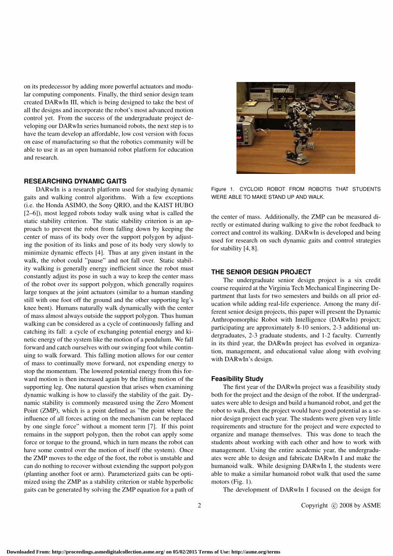
Figure 1. CYCLOID ROBOT FROM ROBOTIS THAT STUDENTSWERE ABLE TO MAKE STAND UP AND WALK.
the center of mass. Additionally, the ZMP can be measured di-rectly or estimated during walking to give the robot feedback tocorrect and control its walking. DARwIn is developed and beingused for research on such dynamic gaits and control strategiesfor stability [4, 8].
THE SENIOR DESIGN PROJECTThe undergraduate senior design project is a six credit
course required at the Virginia Tech Mechanical Engineering De-partment that lasts for two semesters and builds on all prior ed-ucation while adding real-life experience. Among the many dif-ferent senior design projects, this paper will present the DynamicAnthropomorphic Robot with Intelligence (DARwIn) project;participating are approximately 8-10 seniors, 2-3 additional un-dergraduates, 2-3 graduate students, and 1-2 faculty. Currentlyin its third year, the DARwIn project has evolved in organiza-tion, management, and educational value along with evolvingwith DARwIn’s design.
Feasibility StudyThe first year of the DARwIn project was a feasibility study
both for the project and the design of the robot. If the undergrad-uates were able to design and build a humanoid robot, and get therobot to walk, then the project would have good potential as a se-nior design project each year. The students were given very littlerequirements and structure for the project and were expected toorganize and manage themselves. This was done to teach thestudents about working with each other and how to work withmanagement. Using the entire academic year, the undergradu-ates were able to design and fabricate DARwIn I and make thehumanoid walk. While designing DARwIn I, the students wereable to make a similar humanoid robot walk that used the samemotors (Fig. 1).
The development of DARwIn I focused on the design for
Copyright c© 2008 by ASME
erms of Use: http://asme.org/terms
Do
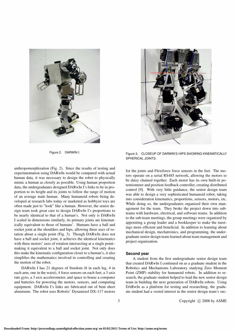
Figure 2. DARWIN I.
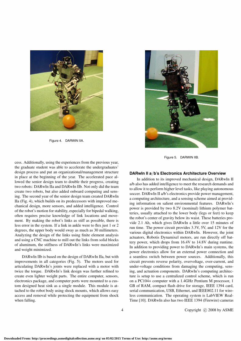
anthropomorphization (Fig. 2). Since the results of testing andexperimentation using DARwIn would be compared with actualhuman data, it was necessary to design the robot to physicallymimic a human as closely as possible. Using human proportiondata, the undergraduates designed DARwIn I’s links to be in pro-portion to its height and its joints to follow the range of motionof an average male human. Many humanoid robots being de-veloped at research labs today or marketed as hobbyist toys areoften made just to ”look” like a human. However, the senior de-sign team took great care to design DARwIn I’s proportions tobe nearly identical to that of a human’s. Not only is DARwInI scaled in dimensions similarly, its primary joints are kinemat-ically equivalent to those of humans’. Humans have a ball andsocket joint at the shoulders and hips, allowing three axes of ro-tation about a single point (Fig. 3). Though DARwIn does nothave a ball and socket joint, it achieves the identical kinematicswith three motors’ axes of rotation intersecting at a single point–making it equivalent to a ball and socket joint. Not only doesthis make the kinematic configuration closer to a human’s, it alsosimplifies the mathematics involved in controlling and creatingthe motion of the robot.
DARwIn I has 21 degrees of freedom (6 in each leg, 4 ineach arm, one in the waist), 4 force sensors on each feet, a 3 axisrate gyro, a 3 axis accelerometer, and space to house a computerand batteries for powering the motors, sensors, and computingequipment. DARwIn I’s links are fabricated out of bent sheetaluminum. The robot uses Robotis’ Dynamixel DX-117 motors
3
wnloaded From: http://proceedings.asmedigitalcollection.asme.org/ on 05/02/2015 Te
Figure 3. CLOSEUP OF DARWIN’S HIPS SHOWING KINEMATICALLYSPHERICAL JOINTS.
for the joints and Flexiforce force sensors in the feet. The mo-tors operate on a serial RS485 network, allowing the motors tobe daisy chained together. Each motor has its own built-in po-tentiometer and position feedback controller, creating distributedcontrol [9]. With very little guidance, the senior design teamwas able to design a very sophisticated humanoid robot, takinginto consideration kinematics, proportions, sensors, motors, etc.While doing so, the undergraduates organized their own man-agement for the team. They broke the project down into sub-teams with hardware, electrical, and software teams. In additionto the sub-team meetings, the group meetings were organized byappointing a group leader and a bookkeeper to make the meet-ings more efficient and beneficial. In addition to learning aboutmechanical design, mechatronics, and programming, the under-graduate senior design team learned about team management andproject organization.
Second yearA student from the first undergraduate senior design team
that created DARwIn I continued on as a graduate student in theRobotics and Mechanisms Laboratory studying Zero MomentPoint (ZMP) stability for humanoid robots. In addition to re-search, the graduate student helped to lead the new senior designteam in building the next generation of DARwIn robots. UsingDARwIn as a platform for testing and researching, the gradu-ate student had a vested interest in the senior design team’s suc-
Copyright c© 2008 by ASME
rms of Use: http://asme.org/terms
Do
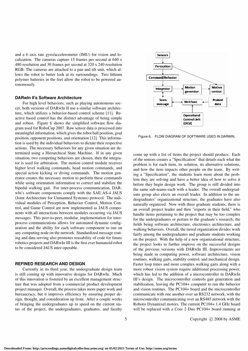
Figure 4. DARWIN IIA.
cess. Additionally, using the experiences from the previous year,the graduate student was able to accelerate the undergraduates’design process and put an organizational/management structurein place at the beginning of the year. The accelerated pace al-lowed the senior design team to double their progress, creatingtwo robots: DARwIn IIa and DARwIn IIb. Not only did the teamcreate two robots, but also added onboard computing and sens-ing. The second year of the senior design team created DARwInIIa (Fig. 4), which builds on its predecessors with improved me-chanical design, more sensors, and added intelligence. Controlof the robot’s motion for stability, especially for bipedal walking,often requires precise knowledge of link locations and move-ment. By making the robot’s links as stiff as possible, there isless error in the system. If a link in ankle were to flex just 1 or 2degrees, the upper body would sway as much as 30 millimeters.Analyzing the design of the links using finite element analysisand using a CNC machine to mill out the links from solid blocksof aluminum, the stiffness of DARwIn’s links were maximizedand weight minimized.
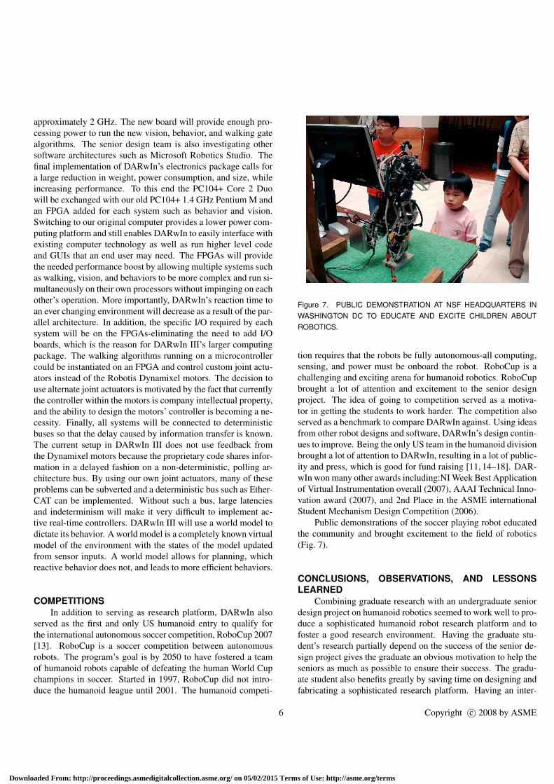
DARwIn IIb is based on the design of DARwIn IIa, but withimprovements in all categories (Fig. 5). The motors used forarticulating DARwIn’s joints were replaced with a motor withtwice the torque. DARwIn’s link design was further refined tocreate even lighter weight parts. The entire computer, sensors,electronics package, and computer ports were mounted to a cus-tom designed heat sink as a single module. This module is at-tached to the robot body using shock mounts, which allows easyaccess and removal while protecting the equipment from shockwhen falling.
4
wnloaded From: http://proceedings.asmedigitalcollection.asme.org/ on 05/02/2015 T
Figure 5. DARWIN IIB.
DARwIn II a/b’s Electronics Architecture OverviewIn addition to its improved mechanical design, DARwIn II
a/b also has added intelligence to meet the research demands andto allow it to perform higher level tasks, like playing autonomoussoccer. DARwIn II a/b’s electronics provide power management,a computing architecture, and a sensing scheme aimed at provid-ing information on salient environmental features. DARwIn’spower is provided by two 8.2V (nominal) lithium polymer bat-teries, usually attached to the lower body (legs or feet) to keepthe robot’s center of gravity below its waist. These batteries pro-vide 2.1 Ah, which gives DARwIn a little over 15 minutes ofrun time. The power circuit provides 3.3V, 5V, and 12V for thevarious digital electronics within DARwIn. However, the jointactuators, Robotis Dynamixel motors, are run directly off bat-tery power, which drops from 16.4V to 14.8V during runtime.In addition to providing power to DARwIn’s main systems, thepower electronics allow for an external power connection anda seamless switch between power sources. Additionally, thiscircuit prevents reverse polarity, overvoltage, over-current, andunder-voltage conditions from damaging the computing, sens-ing, and actuation components. DARwIn’s computing architec-ture is setup to use a centralized control scheme, which is runon a PC104+ computer with a 1.4GHz Pentium M processor, 1GB of RAM, compact flash drive for storage, IEEE 1394 card,serial communication, USB, Ethernet, and IEEE802.11 for wire-less communication. The operating system is LabVIEW Real-Time [10]. DARwIn also has two IEEE 1394 (Firewire) cameras
Copyright c© 2008 by ASME
erms of Use: http://asme.org/terms
Do
and a 6 axis rate gyro/accelerometer (IMU) for vision and lo-calization. The cameras capture 15 frames per second at 640 x480 resolution and 30 frames per second at 320 x 240 resolutionRGB. The cameras are attached to a pan and tilt unit, which al-lows the robot to better look at its surroundings. Two lithiumpolymer batteries in the feet allow the robot to be powered au-tonomously.
DARwIn II’s Software ArchitectureFor high level behaviors, such as playing autonomous soc-
cer, both versions of DARwIn II use a similar software architec-ture, which utilizes a behavior-based control scheme [11]. Re-active based control has the distinct advantage of being simpleand robust. Figure 6 shows the simplified software flow dia-gram used for RoboCup 2007. Raw sensor data is processed intomeaningful information, which gives the robot ball position, goalposition, opponent positions, and orientation [12]. This informa-tion is used by the individual behaviors to dictate their respectiveactions. The necessary behaviors for any given situation are de-termined using a Hierarchical State Machine. If in any givensituation, two competing behaviors are chosen, then the integra-tor is used for arbitration. The motion control module receiveshigher level walking commands, head motion commands, andspecial action kicking or diving commands. The motion gen-erator creates the necessary motion to perform these commandswhile using orientation information to correct and stabilize thebipedal walking gait. For inter-process communication, DAR-wIn’s software components comply with the SAE AS-4 JAUS(Joint Architecture for Unmanned Systems) protocol. The indi-vidual modules of Perception, Behavior Control, Motion Con-trol, and Game Control are now implemented as JAUS compo-nents with all interactions between modules occurring via JAUSmessages. This peer-to-peer, modular, implementation for inter-process communications allows for automated dynamic config-uration and the ability for each software component to run onany computing node on the network. Standardized message rout-ing and data serving also promotes reusability of code for futurerobotics projects and DARwIn III is the first ever humanoid robotto be considered JAUS inter-operable.
REFINED RESEARCH AND DESIGNCurrently in its third year, the undergraduate design team
is still coming up with innovative designs for DARwIn. Muchof this innovation is fostered by an excellent management struc-ture that was adopted from a commercial product developmentproject manager. Overall, the process takes more paper work andbureaucracy, but it improves efficiency by ensuring proper de-sign, thought, and consideration up front. After a couple weeksof bringing the undergraduates up to speed on the current sta-tus of the project, the undergraduates, graduates, and faculty
5
wnloaded From: http://proceedings.asmedigitalcollection.asme.org/ on 05/02/2015 T
Figure 6. FLOW DIAGRAM OF SOFTWARE USED IN DARWIN.
come up with a list of items the project should produce. Eachof the seniors creates a ”Specification” that details each what theproblem is for each item, its solution, its alternative solutions,and how the item impacts other people on the team. By writ-ing a ”Specification”, the students learn more about the prob-lem they are solving and have a better idea of how to solve itbefore they begin design work. The group is still divided intothe same sub-teams-each with a leader. The overall undergrad-uate group also elects an overall leader. In addition to the un-dergraduates’ organizational structure, the graduates have alsonaturally organized. Now with three graduate students, there isan overall project leader and then ”experts in their field,” whohandle items pertaining to the project that may be too complexfor the undergraduates or pertain to the graduate’s research; thefields being software architecture, electronics architecture, andwalking behaviors. Overall, the tiered organization divides workfairly among the undergraduates and graduate students workingon the project. With the help of a new organizational structure,the project looks to further improve on the successful designsof the previous versions with DARwIn III. Improvements arebeing made in computing power, software architecture, visionroutines, walking gaits, stability control, and mechanical design.Faster loop times and more complex walking gaits along with amore robust vision system require additional processing power,which has led to the addition of a microcontroller in DARwInIII’s design. The microcontroller controls gait generation andstabilization, leaving the PC104+ computer to run the behaviorand vision routines. The PC104+ board and the microcontrollercommunicate with one another over an RS232 network, with themicrocontroller communicating over an RS485 network with theRobotis Dynamixel motors. The current PC104+ 1.4 GHz boardwill be replaced with a Core 2 Duo PC104+ board running at
Copyright c© 2008 by ASME
erms of Use: http://asme.org/terms
Do
approximately 2 GHz. The new board will provide enough pro-cessing power to run the new vision, behavior, and walking gatealgorithms. The senior design team is also investigating othersoftware architectures such as Microsoft Robotics Studio. Thefinal implementation of DARwIn’s electronics package calls fora large reduction in weight, power consumption, and size, whileincreasing performance. To this end the PC104+ Core 2 Duowill be exchanged with our old PC104+ 1.4 GHz Pentium M andan FPGA added for each system such as behavior and vision.Switching to our original computer provides a lower power com-puting platform and still enables DARwIn to easily interface withexisting computer technology as well as run higher level codeand GUIs that an end user may need. The FPGAs will providethe needed performance boost by allowing multiple systems suchas walking, vision, and behaviors to be more complex and run si-multaneously on their own processors without impinging on eachother’s operation. More importantly, DARwIn’s reaction time toan ever changing environment will decrease as a result of the par-allel architecture. In addition, the specific I/O required by eachsystem will be on the FPGAs-eliminating the need to add I/Oboards, which is the reason for DARwIn III’s larger computingpackage. The walking algorithms running on a microcontrollercould be instantiated on an FPGA and control custom joint actu-ators instead of the Robotis Dynamixel motors. The decision touse alternate joint actuators is motivated by the fact that currentlythe controller within the motors is company intellectual property,and the ability to design the motors’ controller is becoming a ne-cessity. Finally, all systems will be connected to deterministicbuses so that the delay caused by information transfer is known.The current setup in DARwIn III does not use feedback fromthe Dynamixel motors because the proprietary code shares infor-mation in a delayed fashion on a non-deterministic, polling ar-chitecture bus. By using our own joint actuators, many of theseproblems can be subverted and a deterministic bus such as Ether-CAT can be implemented. Without such a bus, large latenciesand indeterminism will make it very difficult to implement ac-tive real-time controllers. DARwIn III will use a world model todictate its behavior. A world model is a completely known virtualmodel of the environment with the states of the model updatedfrom sensor inputs. A world model allows for planning, whichreactive behavior does not, and leads to more efficient behaviors.
COMPETITIONSIn addition to serving as research platform, DARwIn also
served as the first and only US humanoid entry to qualify forthe international autonomous soccer competition, RoboCup 2007[13]. RoboCup is a soccer competition between autonomousrobots. The program’s goal is by 2050 to have fostered a teamof humanoid robots capable of defeating the human World Cupchampions in soccer. Started in 1997, RoboCup did not intro-duce the humanoid league until 2001. The humanoid competi-
6
wnloaded From: http://proceedings.asmedigitalcollection.asme.org/ on 05/02/2015 T
Figure 7. PUBLIC DEMONSTRATION AT NSF HEADQUARTERS INWASHINGTON DC TO EDUCATE AND EXCITE CHILDREN ABOUTROBOTICS.
tion requires that the robots be fully autonomous-all computing,sensing, and power must be onboard the robot. RoboCup is achallenging and exciting arena for humanoid robotics. RoboCupbrought a lot of attention and excitement to the senior designproject. The idea of going to competition served as a motiva-tor in getting the students to work harder. The competition alsoserved as a benchmark to compare DARwIn against. Using ideasfrom other robot designs and software, DARwIn’s design contin-ues to improve. Being the only US team in the humanoid divisionbrought a lot of attention to DARwIn, resulting in a lot of public-ity and press, which is good for fund raising [11, 14–18]. DAR-wIn won many other awards including:NI Week Best Applicationof Virtual Instrumentation overall (2007), AAAI Technical Inno-vation award (2007), and 2nd Place in the ASME internationalStudent Mechanism Design Competition (2006).
Public demonstrations of the soccer playing robot educatedthe community and brought excitement to the field of robotics(Fig. 7).
CONCLUSIONS, OBSERVATIONS, AND LESSONSLEARNED
Combining graduate research with an undergraduate seniordesign project on humanoid robotics seemed to work well to pro-duce a sophisticated humanoid robot research platform and tofoster a good research environment. Having the graduate stu-dent’s research partially depend on the success of the senior de-sign project gives the graduate an obvious motivation to help theseniors as much as possible to ensure their success. The gradu-ate student also benefits greatly by saving time on designing andfabricating a sophisticated research platform. Having an inter-
Copyright c© 2008 by ASME
erms of Use: http://asme.org/terms
Do
national competition for the project-especially one that is inter-nationally popular-helps to motivate the undergraduate studentsand also brings public attention and media, which can lead toadditional funding for the project. An organizational structureis extremely desirable to have in place to make the design pro-cess efficient. Having an experienced member (either faculty orgraduate student) heavily involved in the project also seems tobe very important in achieving excellent results in design. Theinternational competition is a fantastic motivator, but too muchstress on the competition tends to distract the team from the realgoal of the project, which is to create a research platform. Toomuch stress on competition can also be very disappointing if thecompetition results are not as expected. In any case, the compe-titions give valuable experience and design ideas, which can beused for future projects.
ACKNOWLEDGMENTThe authors would like to thank the National Science Foun-
dation for their support for part of this work under Grant No.0730206. The authors would also like to thank JOUSTER andthe 2005-2006, 2006-2007, and 2007-2008 senior design teams.
REFERENCES[1] Hong, D., 2006. “Biologically inspired locomotion strate-
gies: Novel ground mobile robots at romela”. 3rd Interna-tional Conference on Ubiquitous Robots and Ambient In-telligence, Seoul, S. Korea, October.
[2] Hirai, K., 1998. “The development of honda hu-manoid robot”. IEEE Int. Conf. on Robotics nd Automa-tion(Leuven, Belgium), pp. 1321–1326.
[3] Ishida, T., 2003. “A small biped entertainment robot sdr-4x ii”. Proc. IEEE Symposium on Comp. Intelligence inRobotics and Automation, July, pp. 1046–1051.
[4] Kim, J., 2006. “On the Stable Dynamic Walking of BipedHumanoid Robots”. PhD Thesis, Korea Advanced Instituteof Science and Technology, Daejeon, South Korea.
[5] S. H. Collins, e. a., 2001. “A three-dimensional passive-dynamic walking robot with two legs and knees”. Int. Jour-nal of Robotics Research, 20(2), pp. 607–615.
[6] McGeer, T., 1990. “Passive dynamic walking”. Int. Journalof Robotics Research, 9(2), April, pp. 62–82.
[7] Vukobratovic, M., 2004. “Zero-moment point–thirty fiveyears of its life”. Int. Journal of Humanoid Robotics, 1(1).
[8] Huang, Q., Yokoi, K., and S. Kajita, e. a., 2001. “Plan-ning walking patterns for a biped robot”. IEEE Trans. onRobotics and Automation, 17(3), June, pp. 280–289.
[9] Kim, K., Son, Y., and Kim, P., 2004. “Construction ofsmall humanoids with a new joint actuator module”. Proc.2004 IEEE Int. Conf. on Robotics and Automation, April,pp. 4510–4514.
7
wnloaded From: http://proceedings.asmedigitalcollection.asme.org/ on 05/02/2015 Ter
[10] Shekhar, S., and Muecke, K., 2007. “Teaching completeembedded systems design process with graphical systemdesign methodologies”. 1st Asia-Pacific Workshop on Em-bedded System Education and Research, December.
[11] Muecke, K., and Hong, D., 2007. “A reactive approachto behavior based control of a soccer playing humanoidrobot”. Proc. UKC Conference, August.
[12] Instruments, N., 2005. “Ni vision, imaq vision conceptsmanual”.
[13] Muecke, K., and Hong, D., 2007. “Darwin’s evolution: De-velopment of a humanoid robot”. Proc. IEEE/RSJ Int. Conf.on Intelligent Robots and Systems, October-November,pp. 2574–2575.
[14] Muecke, K., and Hong, D., 2007. “Darwin’s evolution: De-velopment of a humanoid robot for research and evolution”.Industrial Embedded Systems, December.
[15] Muecke, K., Cox, P., and Hong, D., 2006. “Darwin:Dynamic anthropomorphic robot with intelligence, part 1-concept and general overview”. SERVO Magazine, 4(12),December.
[16] Muecke, K., Cox, P., and Hong, D., 2007. “Darwin:Dynamic anthropomorphic robot with intelligence, part 2-parts, wires and motors”. SERVO Magazine, 5(1), January.
[17] Muecke, K., Mayo, R., and Hong, D., 2007. “Darwin:Dynamic anthropomorphic robot with intelligence, part 3-darwin 2.0: The next generation”. SERVO Magazine, 5(2),February.
[18] Hong, D., Muecke, K., Mayo, R., Hurdus, J., and Pullins,B., 2007. “Robocup 2007. darwin’s first soccer tournament:America’s first entry to the humanoid division of robocup”.SERVO Magazine, September.
Copyright c© 2008 by ASME
ms of Use: http://asme.org/terms