Embed Size (px)
DESCRIPTION
The SuperB Accelerator. M. Biagini for the SuperB Accelerator Team Epiphany 2012 Conference Krakow, January 9-11, 2012. SuperB Accelerator. SuperB is a 2 rings, asymmetric energies (e - @ 4.18, e + @ 6.7 GeV) collider with: - PowerPoint PPT Presentation
Citation preview
The SuperB Accelerator
M. Biagini for the SuperB Accelerator Team
Epiphany 2012 ConferenceKrakow, January 9-11, 2012
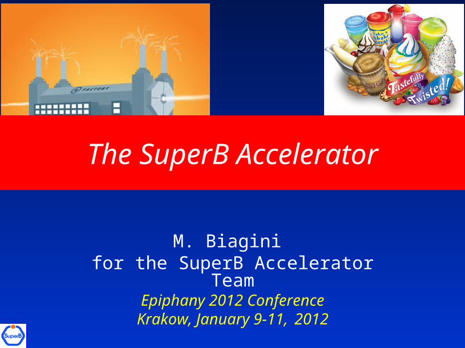
SuperB AcceleratorSuperB is a 2 rings, asymmetric energies (e- @ 4.18, e+ @ 6.7 GeV) collider with: large Piwinski angle and “crab waist” (LPA & CW) collision scheme ultra low emittance lattices longitudinally polarized electron beam target luminosity of 1036 cm-2 s-1 at the (4S) possibility to run at /charm threshold with L = 1035 cm-2 s-1
Criterias used for the design: Minimize building costs Minimize running costs Minimize wall-plug power and water consumption Reuse of some PEP-II B-Factory hardware (magnets, RF)
SuperB can be also a good “light source”: there will be some Sinchrotron Radiation beamlines (collaboration with Italian Institute of Technology)
2
3
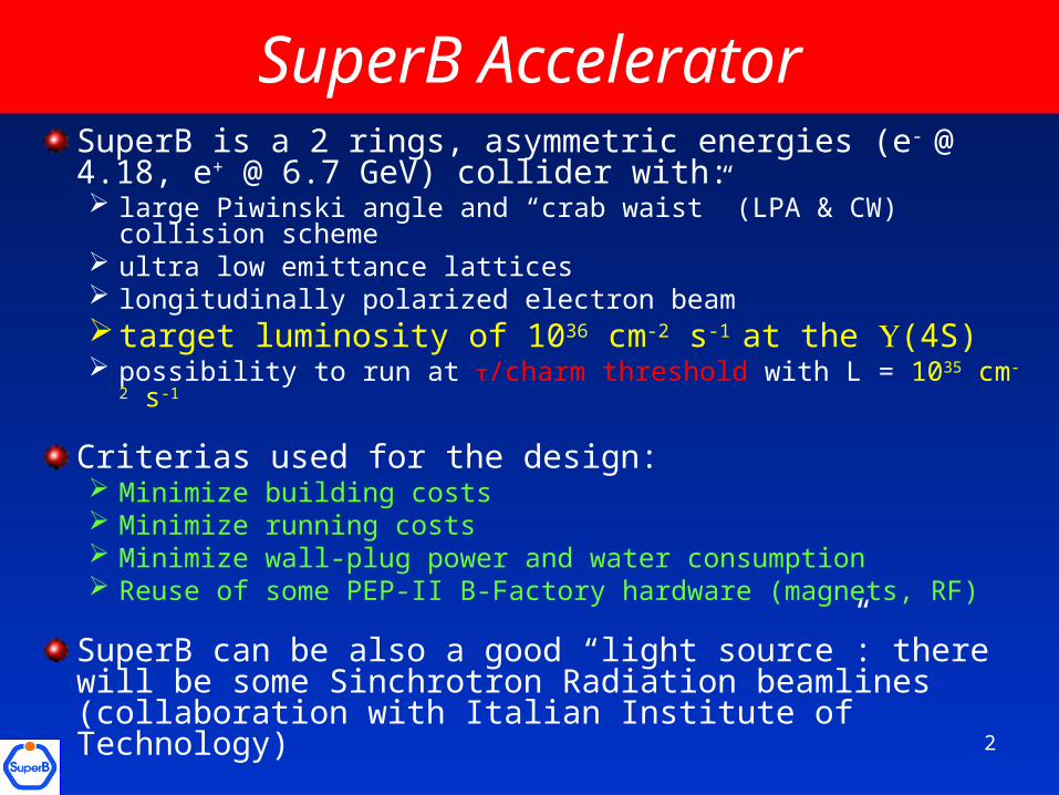
World e+e- colliders luminosity
B-Factories-FactoriesFuture Colliders
1027
1029
1031
1033
1035
0.1 1 10 100 1000
Lu
min
os
ity
(cm
-2 s
-1)
c.m. Energy (GeV)
ADONE
DCI
ADONE
VEPP-2M
VEPP2000
DANE
BEPC
SPEAR2
VEPP-4M PETRAPETRA
PEPDORIS2
BEPCII CESR
PEP-II
KEKB
LEP
LEP
LEP
LEP
ILC
CLIC
SUPERKEKB
SuperB
BINP c-
CESR -c
SuperFactories
Factories
Linear collidersSuperB
SuperB: highest world luminosity collider ever
Ultra-low emittance
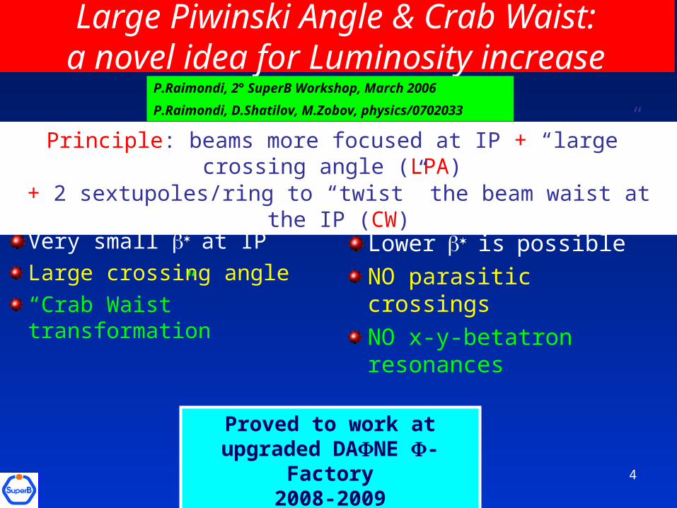
Very small at IP
Large crossing angle
“Crab Waist” transformation
Small collision area
Lowerispossible
NO parasitic crossings
NO x-y-betatron resonances
Principle: beams more focused at IP + “large” crossing angle (LPA) + 2 sextupoles/ring to “twist” the beam waist at the IP (CW)
Large Piwinski Angle & Crab Waist:a novel idea for Luminosity increase
Proved to work at upgraded DANE -Factory
2008-2009
P.Raimondi, 2° SuperB Workshop, March 2006
P.Raimondi, D.Shatilov, M.Zobov, physics/0702033
4
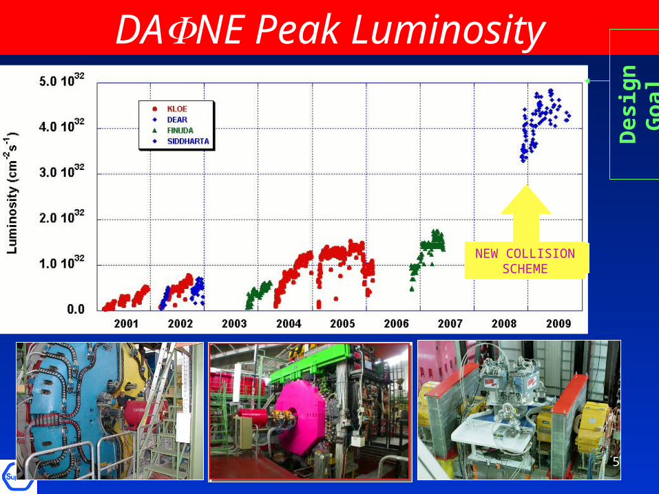
NEW COLLISION SCHEME
DANE Peak Luminosity
Des
ign
Go
al
5
6
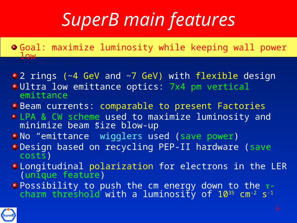
SuperB main features
Goal: maximize luminosity while keeping wall power low
2 rings (~4 GeV and ~7 GeV) with flexible designUltra low emittance optics: 7x4 pm vertical emittanceBeam currents: comparable to present Factories LPA & CW scheme used to maximize luminosity and minimize beam size blow-upNo “emittance” wigglers used (save power)Design based on recycling PEP-II hardware (save costs)Longitudinal polarization for electrons in the LER (unique feature)Possibility to push the cm energy down to the -charm threshold with a luminosity of 1035 cm-2 s-1
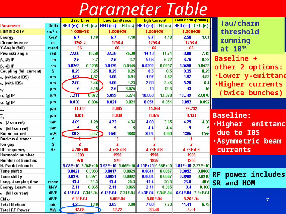
Parameter Table
Baseline + other 2 options:•Lower y-emittance•Higher currents (twice bunches)
Tau/charmthreshold runningat 1035
Baseline: •Higher emittance due to IBS•Asymmetric beam currents
RF power includes SR and HOM
7
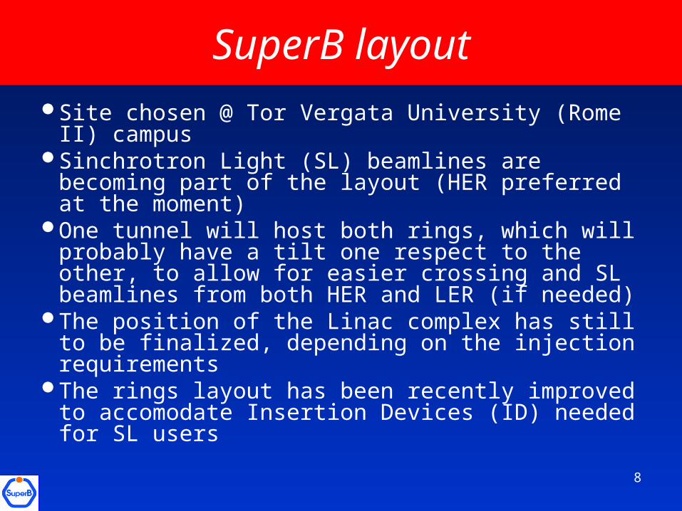
SuperB layout
Site chosen @ Tor Vergata University (Rome II) campus
Sinchrotron Light (SL) beamlines are becoming part of the layout (HER preferred at the moment)
One tunnel will host both rings, which will probably have a tilt one respect to the other, to allow for easier crossing and SL beamlines from both HER and LER (if needed)
The position of the Linac complex has still to be finalized, depending on the injection requirements
The rings layout has been recently improved to accomodate Insertion Devices (ID) needed for SL users
8
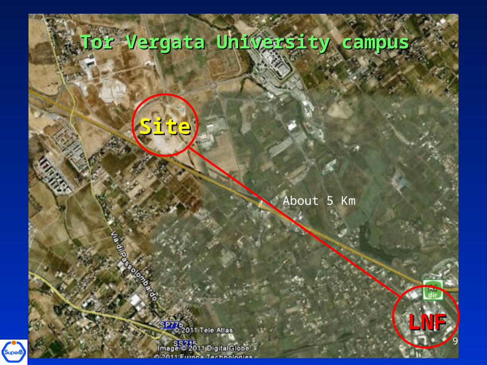
SiteSite
LNFLNF
About 5 Km
Tor Vergata University campusTor Vergata University campus
9
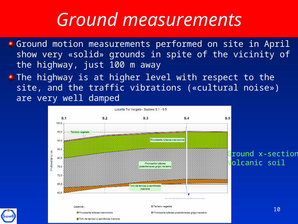
Ground measurementsGround motion measurements performed on site in April show very «solid» grounds in spite of the vicinity of the highway, just 100 m away
The highway is at higher level with respect to the site, and the traffic vibrations («cultural noise») are very well damped
Ground x-sectionVolcanic soil
10
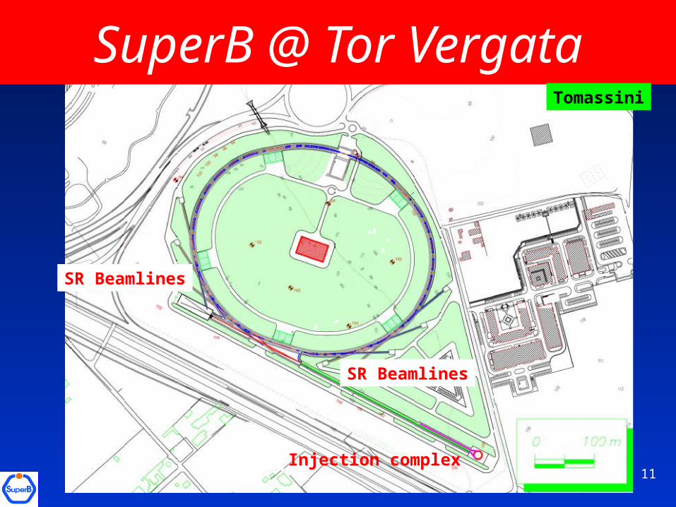
SuperB @ Tor Vergata
SR Beamlines
Injection complex11
SR Beamlines
Tomassini
12
Rings Lattice
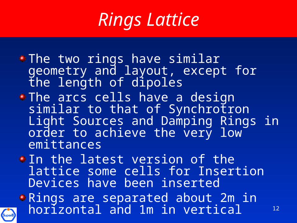
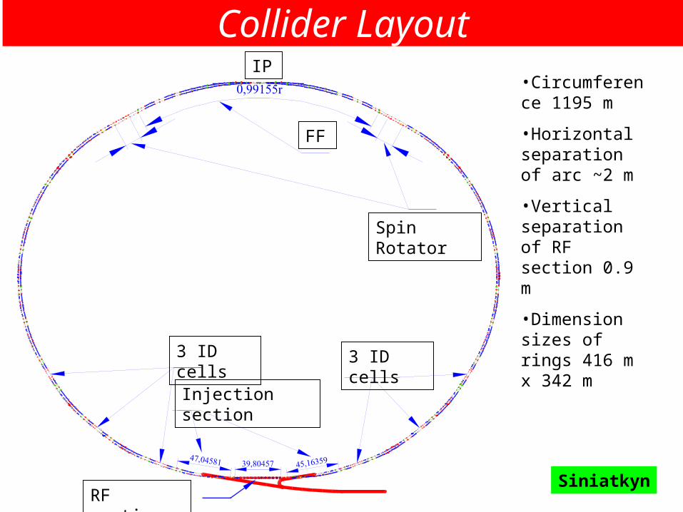
The two rings have similar geometry and layout, except for the length of dipolesThe arcs cells have a design similar to that of Synchrotron Light Sources and Damping Rings in order to achieve the very low emittancesIn the latest version of the lattice some cells for Insertion Devices have been insertedRings are separated about 2m in horizontal and 1m in vertical
Spin Rotator
FF
3 ID cells 3 ID cells
Injection section
RF section
IP•Circumference 1195 m
•Horizontal separation of arc ~2 m
•Vertical separation of RF section 0.9 m
•Dimension sizes of rings 416 m x 342 m
Siniatkyn
Collider Layout
14
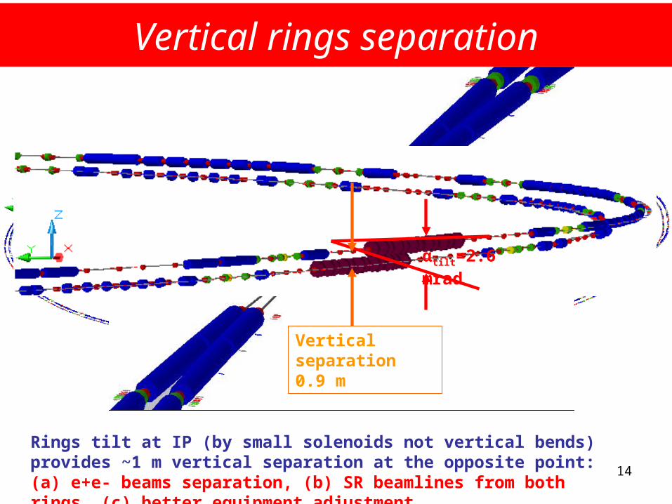
αtilt=2.6 mrad
Vertical separation 0.9 m
Vertical rings separation
Rings tilt at IP (by small solenoids not vertical bends) provides ~1 m vertical separation at the opposite point: (a) e+e- beams separation, (b) SR beamlines from both rings, (c) better equipment adjustment
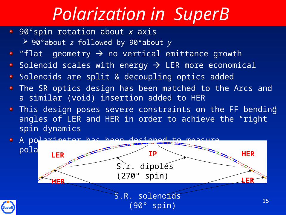
Polarization in SuperB 90°spin rotation about x axis 90°about z followed by 90°about y
“flat” geometry no vertical emittance growth
Solenoid scales with energy LER more economical
Solenoids are split & decoupling optics added
The SR optics design has been matched to the Arcs and a similar (void) insertion added to HER
This design poses severe constraints on the FF bending angles of LER and HER in order to achieve the “right” spin dynamics
A polarimeter has been designed to measure polarization
IP HER
HER LER
LER
S.R. solenoids (90° spin)
S.r. dipoles(270° spin)
15
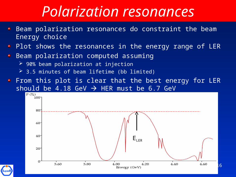
Polarization resonances
ELER
Beam polarization resonances do constraint the beam Energy choice
Plot shows the resonances in the energy range of LER
Beam polarization computed assuming 90% beam polarization at injection 3.5 minutes of beam lifetime (bb limited)
From this plot is clear that the best energy for LER should be 4.18 GeV HER must be 6.7 GeV
16
Interaction RegionThe Interaction Region must satisfy both machine and detector requirements: Final Focus elements as close as possible to the IP Small detector beam pipe Enough beam stay clear small emittance helps Control Synchrotron Radiation backgrounds Have an adequate detector solid angle Magnet vibrations need to be damped (at the level of 10nm) A state-of-the-art luminosity feedback is needed
With the large crossing angle the beam is off-axis in the first quadrupoles, hence it is not only focused but also bent, producing unwanted SR backgrounds and emittance growth
For SuperB a new design of the first doublet with «twins» quadrupoles was developed
17
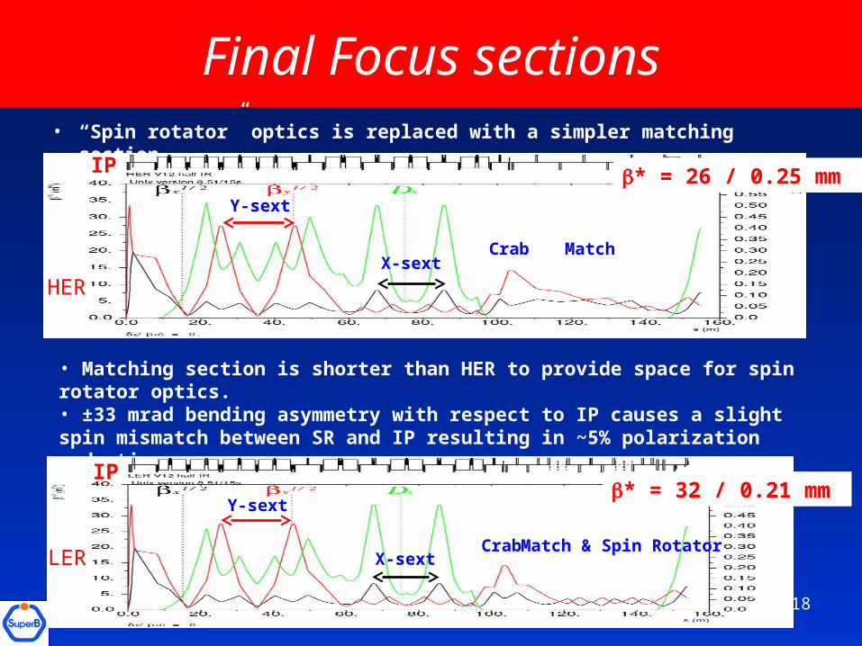
Final Focus sections• “Spin rotator” optics is replaced with a simpler matching section
IP
Y-sext
X-sextMatchCrab
HER
• Matching section is shorter than HER to provide space for spin rotator optics.• ±33 mrad bending asymmetry with respect to IP causes a slight spin mismatch between SR and IP resulting in ~5% polarization reduction.
IP
Y-sext
X-sextMatch & Spin RotatorCrab
LER
* = 26 / 0.25 mm
* = 32 / 0.21 mm
18
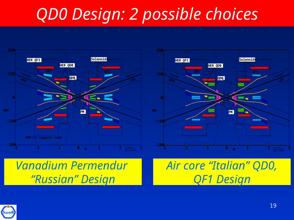
QD0 Design: 2 possible choices
-3 -2 -1 0 1 2 3
0
100
-100
-200
200
mm
m M. Sullivan March, 13, 2010 SB_RL_V12_SF8A_3M
QF1 QF1
QD0
PM
SolenoidsHER QF1
HER QD0
PEP-II Support tube
-3 -2 -1 0 1 2 3
0
100
-100
-200
200
mm
m M. Sullivan March, 13, 2010 SB_RL_V12_SF8A_3M
QF1 QF1
QD0
PM
SolenoidsHER QF1
HER QD0
Vanadium Permendur “Russian” Design
Air core “Italian” QD0, QF1 Design
19
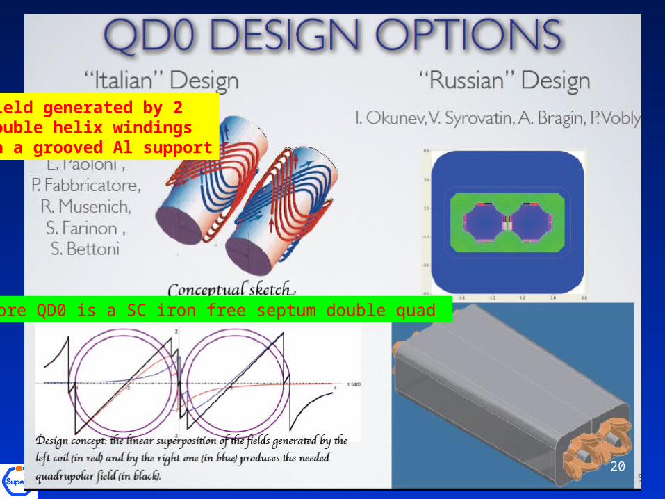
Air-core QD0 is a SC iron free septum double quad
20
Field generated by 2 double helix windingsin a grooved Al support
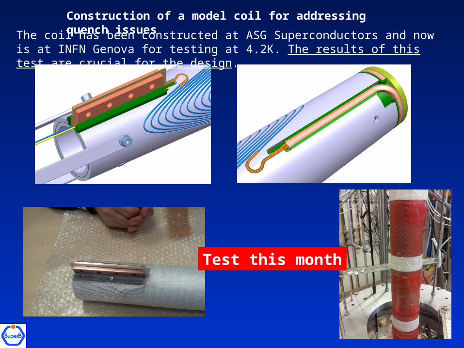
Construction of a model coil for addressing quench issues
The coil has been constructed at ASG Superconductors and now is at INFN Genova for testing at 4.2K. The results of this test are crucial for the design.
Test this month
Collettive effects
Stored beams are subject to effects that can produce instabilities or degrade the beam quality, such as: Intra-Beam-Scattering (IBS) inside the bunch produces
emittance and energy spread growth (not important in Damping Ring)
Electron-cloud instability limits the current threshold of the positron beam needs mitigation methods (ex. solenoids, beam pipe coating, clearing electrodes...)
Fast Ions Instability is critical for the electron beam CSR (Coherent Synchrotron Radiation) degrades beam
quality (not important in Damping Ring)
These effects have been studied and remediation techniques chosen 22
23
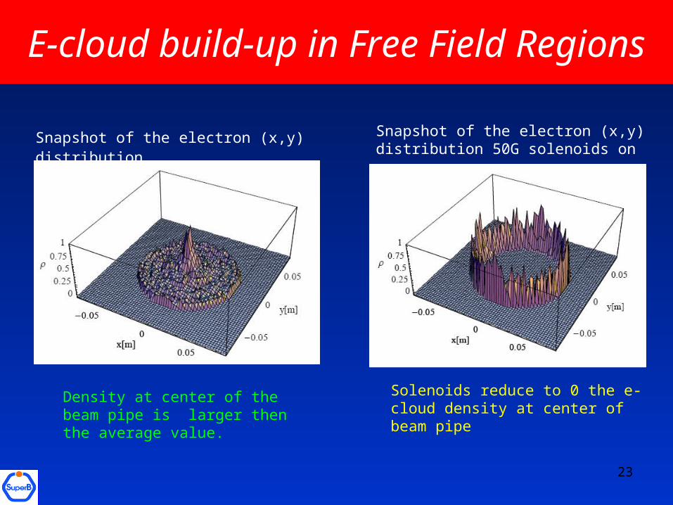
Snapshot of the electron (x,y) distribution
Density at center of the beam pipe is larger then the average value.
E-cloud build-up in Free Field Regions
Snapshot of the electron (x,y) distribution 50G solenoids on
Solenoids reduce to 0 the e-cloud density at center of beam pipe
24
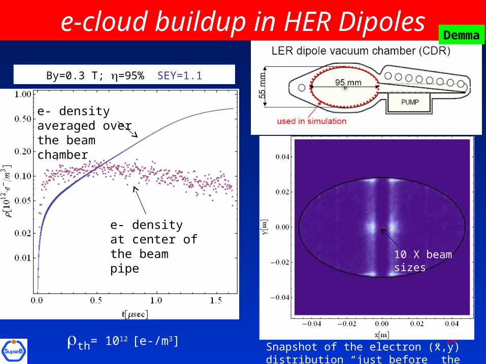
e-cloud buildup in HER Dipoles
By=0.3 T; =95% SEY=1.1
th= 1012 [e-/m3]
e- density at center of the beam pipe
e- density averaged over the beam chamber
10 X beam sizes
Snapshot of the electron (x,y) distribution “just before” the passage of the last bunch
Demma
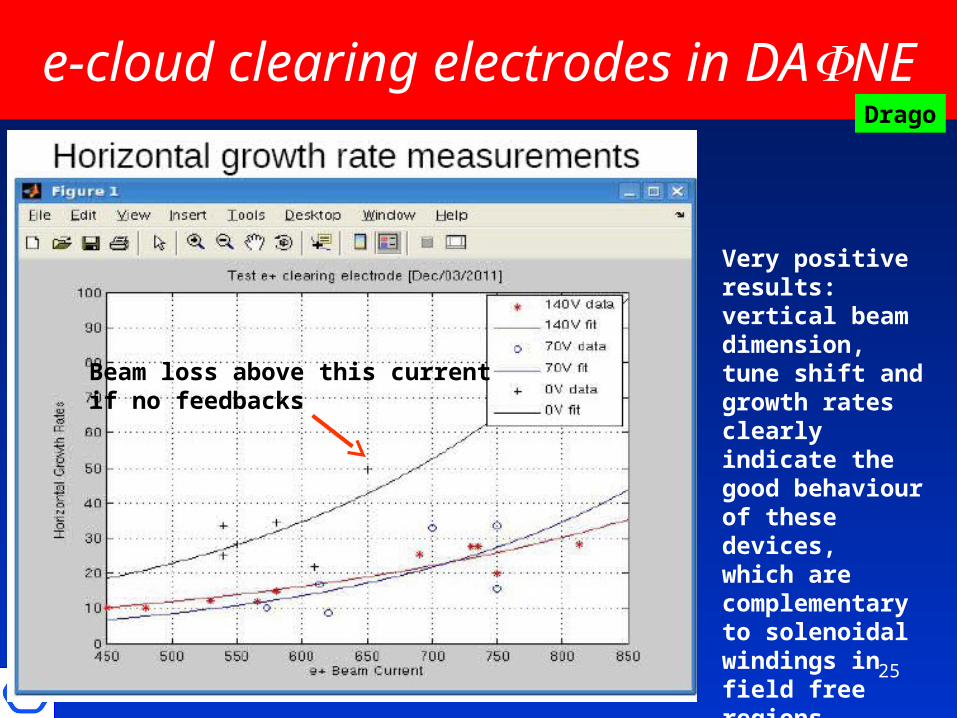
e-cloud clearing electrodes in DANE
Very positive results: vertical beam dimension, tune shift and growth ratesclearly indicate the good behaviour of these devices,which are complementary to solenoidal windings in field free regions
Drago
Beam loss above this current if no feedbacks
25
Low emittance tuningThe extremely low design beam emittance needs to be tuned and minimized careful correction of the magnet alignment and field errors
These errors produce emittance coupling with transfer of some horizontal emittance to the vertical plane this needs to be minimized
Beta-beating (ring -functions are not as in the model machine, but are perturbed by the magnet errors) also needs minimization
Vertical dispersion at IP needs to be corrected to the lowest possible value not to compromise luminosity
26
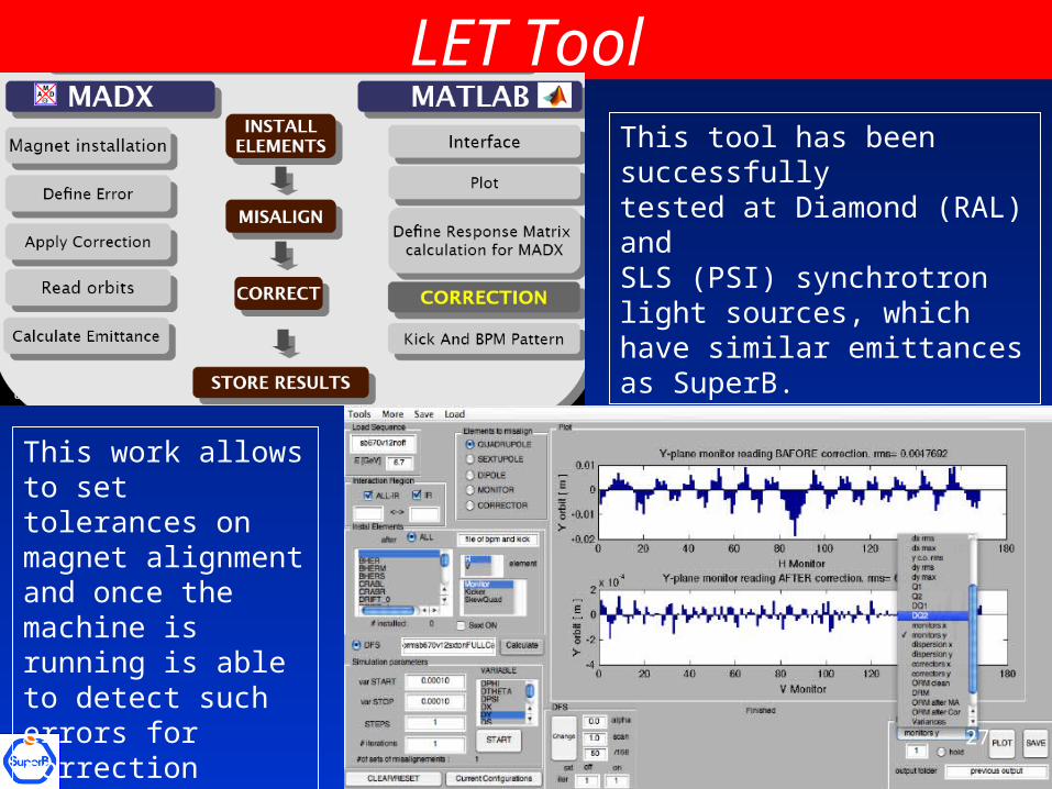
LET ToolThis tool has been successfully tested at Diamond (RAL) and SLS (PSI) synchrotron light sources, which have similar emittances as SuperB.
This work allows to set tolerances on magnet alignment and once the machine is running is able to detect such errors for correction
27
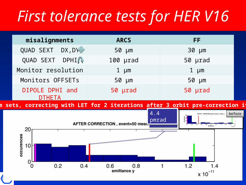
First tolerance tests for HER V16misalignments ARCS FF
QUAD SEXT DX,DY 50 μm 30 μm
QUAD SEXT DPHI 100 μrad 50 μrad
Monitor resolution 1 μm 1 μm
Monitors OFFSETs 50 μm 50 μm
DIPOLE DPHI and DTHETA
50 μrad 50 μrad
50 random sets, correcting with LET for 2 iterations after 3 orbit pre-correction iterations
beforebefore4.4 pmrad4.4 pmrad
Injection System
Injection in top-up requires a very stable, reliable injection complexLatest design:
Only e+ beam is stored in Damping Ring (DR) while e- beam is directly accelerated and injected e+ stored in DR for the time between two injection pulses, achieving same emittance damping factor at twice the repetition frequency possible with a 100 Hz Linac to inject at 50 Hz in each ring using a single bunch per pulse to make the current per bunch very uniform along the bunch trains
Proposal: use SLAC gun (high charge, 10 nC) for the e+ line and have a custom made polarized, low charge, low emittance gun for the e- line
R&D in progress at LAL/Orsay for the positron sourceContacts with SPARC group in Frascati for the low emittance gunR&D at SPARC on C-band Linac maybe useful also (shorter)
Boni, Guiducci,Preger, Variola et al) 29
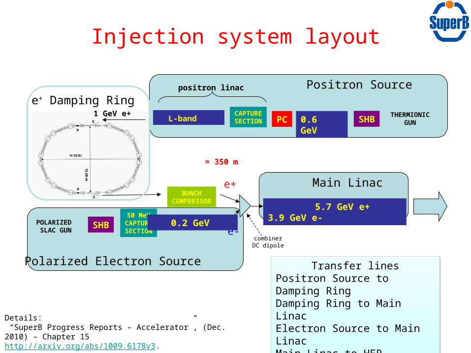
THERMIONICGUNSHB0.6 GeVPC
BUNCHCOMPRESSOR
5.7 GeV e+ 3.9 GeV e-
POLARIZED SLAC GUN
SHB50 MeV
CAPTURESECTION
e+
e-combinerDC dipole
0.2 GeV
CAPTURESECTION
positron linac
1 GeV e+
≈ 350 m
L-band
Positron Source
Polarized Electron Source
Main Linac
e+ Damping Ring
Transfer linesPositron Source to Damping RingDamping Ring to Main LinacElectron Source to Main LinacMain Linac to HERMain Linac to LER
Transfer linesPositron Source to Damping RingDamping Ring to Main LinacElectron Source to Main LinacMain Linac to HERMain Linac to LER
Injection system layout
Details: “SuperB Progress Reports – Accelerator”, (Dec. 2010) – Chapter 15 http://arxiv.org/abs/1009.6178v3. “Updated Design of the Italian SuperB Factory Injection System”, IPAC’11
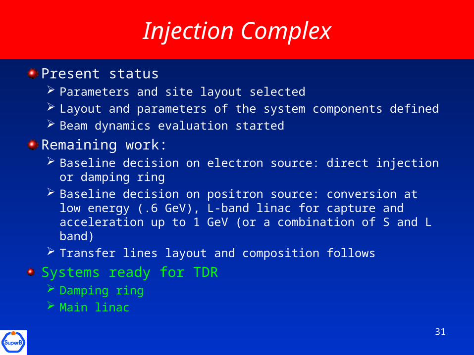
Injection Complex
Present status Parameters and site layout selected Layout and parameters of the system components defined Beam dynamics evaluation started
Remaining work: Baseline decision on electron source: direct injection or damping
ring Baseline decision on positron source: conversion at low energy
(.6 GeV), L-band linac for capture and acceleration up to 1 GeV (or a combination of S and L band)
Transfer lines layout and composition follows
Systems ready for TDR Damping ring Main linac
31
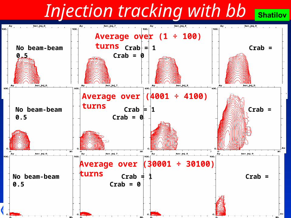
Injection tracking with bb
No beam-beam Crab = 1 Crab = 0.5 Crab = 0
Average over (1 ÷ 100) turns
No beam-beam Crab = 1 Crab = 0.5 Crab = 0
Average over (4001 ÷ 4100) turns
32
No beam-beam Crab = 1 Crab = 0.5 Crab = 0
Average over (30001 ÷ 30100) turns
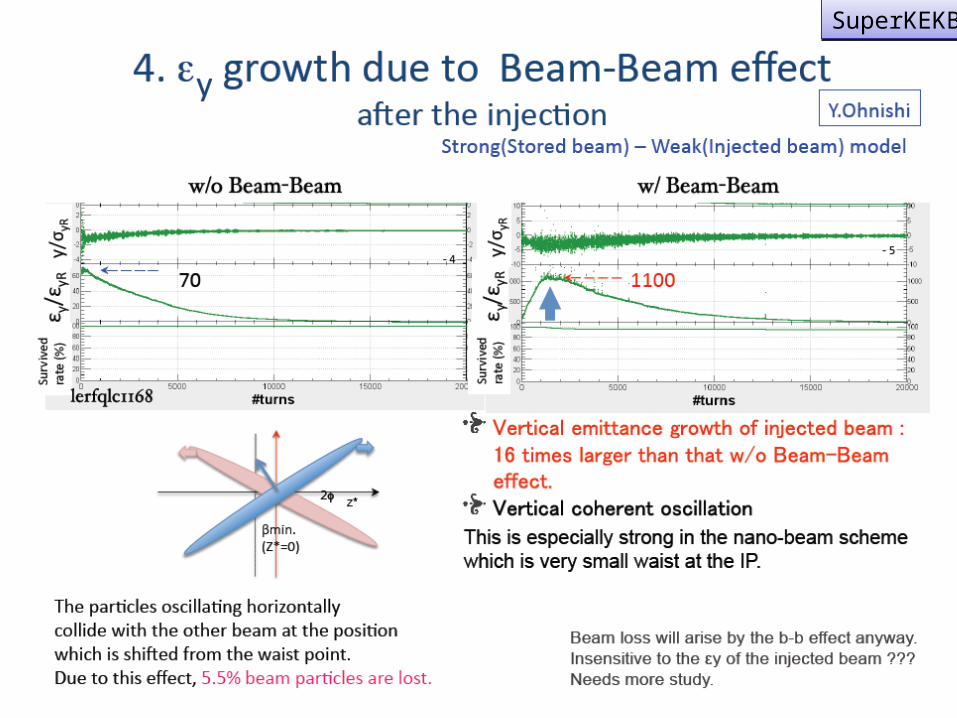
SuperKEKBSuperKEKB
33
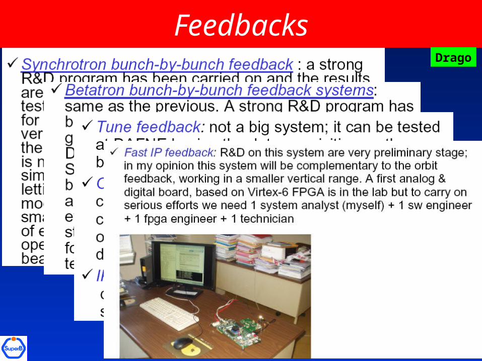
FeedbacksDrago
34
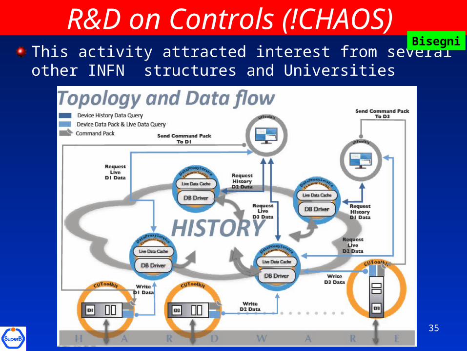
R&D on Controls (!CHAOS) This activity attracted interest from several other INFN structures and Universities
Bisegni
35
SuperB not «just a collider»
36
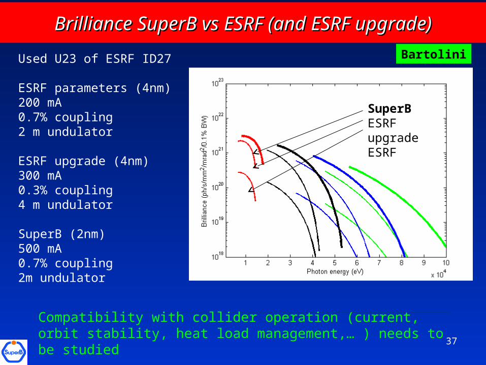
Brilliance SuperB vs ESRF (and ESRF upgrade)Brilliance SuperB vs ESRF (and ESRF upgrade)
Used U23 of ESRF ID27
ESRF parameters (4nm) 200 mA0.7% coupling2 m undulator
ESRF upgrade (4nm) 300 mA0.3% coupling4 m undulator
SuperB (2nm)500 mA0.7% coupling2m undulator
SuperBESRF upgradeESRF
Bartolini
37
Compatibility with collider operation (current, orbit stability, heat load management,… ) needs to be studied
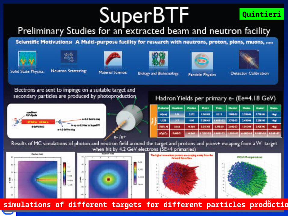
MC simulations of different targets for different particles production
Quintieri
38
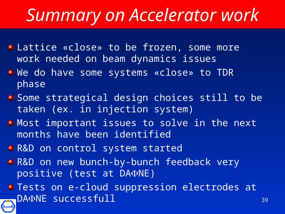
Summary on Accelerator work
Lattice «close» to be frozen, some more work needed on beam dynamics issues
We do have some systems «close» to TDR phase
Some strategical design choices still to be taken (ex. in injection system)
Most important issues to solve in the next months have been identified
R&D on control system started
R&D on new bunch-by-bunch feedback very positive (test at DANE)
Tests on e-cloud suppression electrodes at DANE successfull
39
Organization
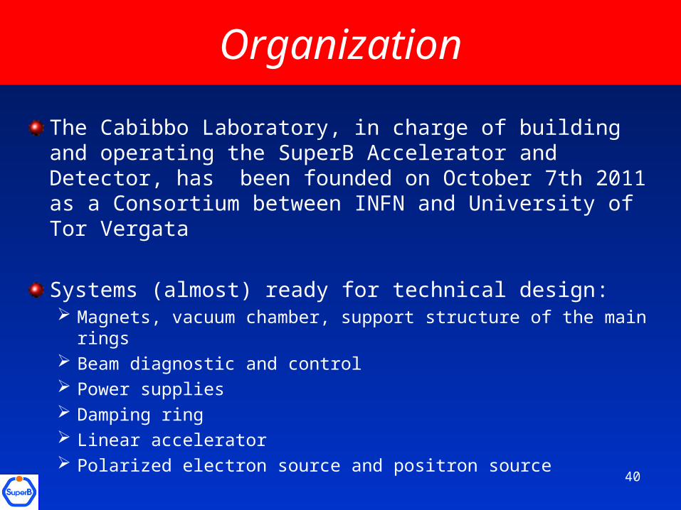
The Cabibbo Laboratory, in charge of building and operating the SuperB Accelerator and Detector, has been founded on October 7th 2011 as a Consortium between INFN and University of Tor Vergata
Systems (almost) ready for technical design: Magnets, vacuum chamber, support structure of the main rings Beam diagnostic and control Power supplies Damping ring Linear accelerator Polarized electron source and positron source
40
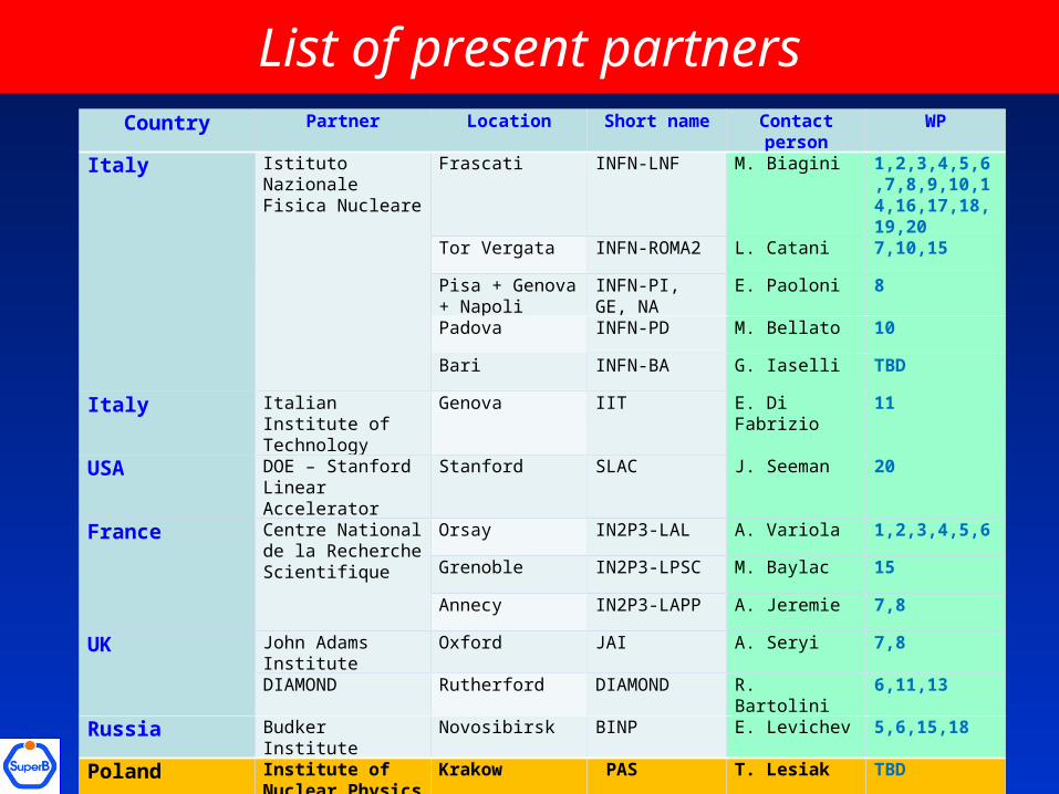
List of present partnersCountry Partner Location Short name Contact
personWP
Italy Istituto Nazionale Fisica Nucleare
Frascati INFN-LNF M. Biagini 1,2,3,4,5,6,7,8,9,10,14,16,17,18,19,20
Tor Vergata INFN-ROMA2 L. Catani 7,10,15
Pisa + Genova + Napoli
INFN-PI, GE, NA
E. Paoloni 8
Padova INFN-PD M. Bellato 10
Bari INFN-BA G. Iaselli TBD
Italy Italian Institute of Technology
Genova IIT E. Di Fabrizio 11
USA DOE – Stanford Linear Accelerator
Stanford SLAC J. Seeman 20
France Centre National de la Recherche Scientifique
Orsay IN2P3-LAL A. Variola 1,2,3,4,5,6
Grenoble IN2P3-LPSC M. Baylac 15
Annecy IN2P3-LAPP A. Jeremie 7,8
UK John Adams Institute
Oxford JAI A. Seryi 7,8
DIAMOND Rutherford DIAMOND R. Bartolini 6,11,13
Russia Budker Institute Novosibirsk BINP E. Levichev 5,6,15,18
Poland Institute of Nuclear Physics PAS
Krakow PAS T. Lesiak TBD
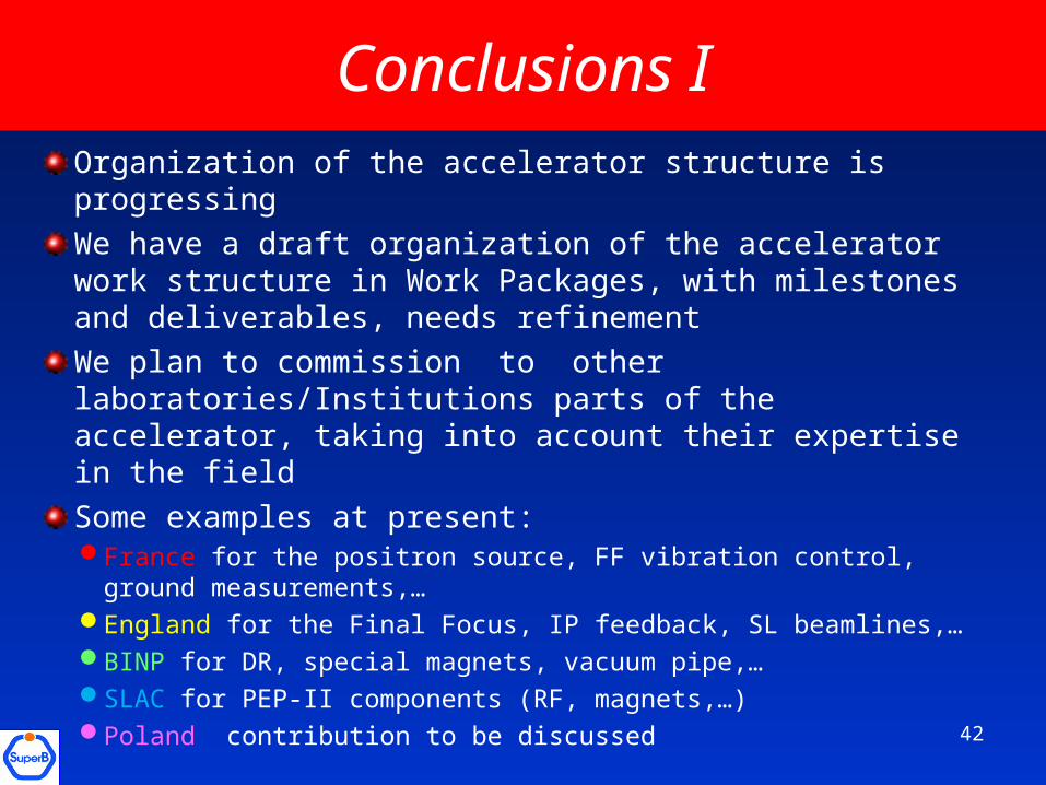
Conclusions IOrganization of the accelerator structure is progressing
We have a draft organization of the accelerator work structure in Work Packages, with milestones and deliverables, needs refinement
We plan to commission to other laboratories/Institutions parts of the accelerator, taking into account their expertise in the field
Some examples at present:France for the positron source, FF vibration control, ground
measurements,… England for the Final Focus, IP feedback, SL beamlines,…BINP for DR, special magnets, vacuum pipe,…SLAC for PEP-II components (RF, magnets,…)Poland contribution to be discussed 42
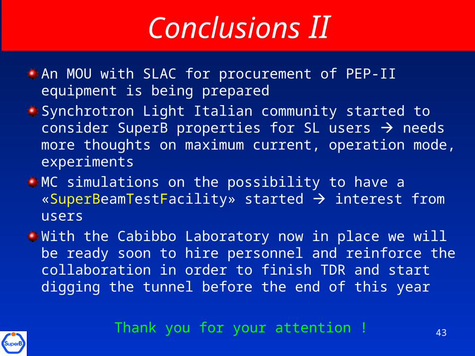
Conclusions IIAn MOU with SLAC for procurement of PEP-II equipment is being prepared
Synchrotron Light Italian community started to consider SuperB properties for SL users needs more thoughts on maximum current, operation mode, experiments
MC simulations on the possibility to have a «SuperBeamTestFacility» started interest from users
With the Cabibbo Laboratory now in place we will be ready soon to hire personnel and reinforce the collaboration in order to finish TDR and start digging the tunnel before the end of this year
Thank you for your attention !43