Embed Size (px)
Citation preview

THE STUDY OF LASER DRILLING OF POLYMERIC MATERIAL
MOHD KHAIRI AZRI BIN SHAPIE
Thesis submitted in partial fulfilment of the requirements
for the award of the degree of Bachelor of Mechanical Engineering
Faculty of Mechanical Engineering
UNIVERSITI MALAYSIA PAHANG
JUNE 2013

vi
ABSTRACT
Polymeric materials is widely used in many applications due to its advantages
character but unfortunately, this polymeric material are fragile and not rigid for their
manufacturing process. In order to overcome this problem, the non-contact laser
drilling process is the best solution. However, poor quality of drill has been rise as
critical issues in industry due to the improper setting of drilling parameters. The
purpose of this study are to study the possibilities of low power laser on drilling
polymeric materials and to identify the optimum parameters in order to obtain a good
geometry of drill hole. There were three different test to be analysed in this analysis
that are depth, kerf width and angle for the laser drilling process. A polymeric
specimen with the thickness of 3 mm were used in this analysis. The Taguchi method
has been applied in this analysis. The results show that the optimum parameter for
the standoff distance is 34 mm while for the optimum drilling time is 10 s is needed
for the depth, kerf width and angle analysis for obtain the best geometry of the hole.
Confirmation test has been done to prove this findings. It is proved that a low power
laser drill machine can be used to drill the polymeric materials and the parameters
stated were the optimum parameters to be used in order to obtain a good geometry
drill hole.

vii
ABSTRAK
Bahan polimer digunakan secara meluas dalam banyak aplikasi disebabkan sifat-sifat
kelebihan tetapi malangnya, bahan polimer ini rapuh dan tidak tegar untuk proses
pembuatan. Dalam usaha untuk mengatasi masalah ini, proses penggerudian tanpa
sentuh laser adalah penyelesaian yang terbaik. Walau bagaimanapun, kualiti
penggerudian laser telah menimbulkan isu-isu kritikal dalam industri kerana
penggunaan parameter penggerudian yang tidak wajar. Tujuan kajian ini adalah
untuk mengkaji kemungkinan laser kuasa rendah untuk menggerudi bahan polimer
dan untuk mengenal pasti parameter yang optimum untuk mendapatkan geometri
yang terbaik bagi lubang gerudi. Terdapat tiga ujian yang berbeza untuk dianalisis
dalam analisis ini iaitu kedalaman, lebar garitan dan sudut untuk proses
penggerudian laser. Satu sampel polimer dengan ketebalan 3 mm telah digunakan
dalam analisis ini. Kaedah Taguchi telah digunakan dalam kajian ini. Keputusan
menunjukkan bahawa parameter optimum untuk jarak ketinggian adalah 34 mm
manakala bagi masa penggerudian optimum adalah 10 s diperlukan untuk analisis
kedalaman, lebar garitan dan sudut untuk mendapatkan geometri yang terbaik
lubang. Ujian pengesahan telah dilakukan untuk membuktikan penemuan ini. Ia
membuktikan bahawa kuasa laser mesin gerudi yang rendah boleh digunakan untuk
menggerudi bahan polimer dan parameter yang dinyatakan adalah parameter
optimum untuk digunakan dalam usaha untuk mendapatkan geometri yang terbaik
bagi lubang gerudi.

viii
TABLE OF CONTENTS
Page
SUPERVISOR’S DECLARATION ii
STUDENT DECLARATION iii
DEDICATION v
ACKNOWLEDGEMENTS vi
ABSTRACT vii
ABSTRAK vii
TABLE OF CONTENT viii
LIST OF TABLE xi
LIST OF FIGURES xii
LIST OF SYMBOL xiv
LIST OF ABBREVIATIONS xv
CHAPTER 1 INTRODUCTION 1
1.1 Introduction 1
1.2 Research Background 2
1.3 Research Objectives 3
1.4 Research Scope 3
1.5 Problem Statement 4
CHAPTER 2 LITERATURE REVIEW 5
2.1 Introduction 5
2.2 Manufacturing Process 5
2.3 Drilling Process 6
2.3.1 Machine Tools of Drilling Process 6
2.3.1.1 Hand Drill 6
2.3.1.2 Laser Drilling 7
2.3.1.3 Micro-electro discharge 7
2.3.1.4 Milling 7
2.4 Laser Drilling 8
2.4.1 Anatomy of Laser Drilling Machine 11
2.4.2 Laser Types 12

ix
2.5 CO₂ Laser 13
2.5.1 CO₂ Laser Working Principle 17
2.5.2 CO₂ Laser Application 20
2.6 CO₂ Laser and Drilling Applications 21
2.7 Polymeric Material 22
2.8 The Taguchi Method for Optimization of Process Parameter 23
2.8.1 Design of Experiment 25
2.8.2 Analysis of Variance (ANOVA) 26
CHAPTER 3 METHODOLOGY 28
3.1 Introduction 28
3.2 Methodology Flow Chart 28
3.3 Laser Drill Machine 30
3.3.1 Laser Drill Machine Development 32
3.3.2 Installation of Limit Switch 33
3.4 Material of the Analysis 34
3.4.1 Properties of the Material 35
3.5 Analysis Parameters 36
3.5.1 Fixed Parameters 36
3.5.2 Variable Parameters 36
3.6 Design of Experiment 37
3.6.1 Taguchi Method 37
3.7 Performing Experiment 40
3.7.1 Experiment Procedures 40
3.8 Evaluation of the Project 42
3.8.1 Experimental Result 42
3.8.2 Drill Hole Evaluation 43
CHAPTER 4 RESULTS AND DISCUSSION 45
4.1 Introduction 45
4.2 Analysis Result (Microstructure Test) 46
4.2.1 The Depth Graph 47
4.2.2 The Kerf Width Graph 48
4.2.3 The Angle Graph 49

x
4.3 Parameters Level 49
4.4 The Taguchi Method for Microstructure Test (Depth) 50
4.4.1 Main Effect (Depth) 51
4.4.2 Main Effect Plot for Mean and S/N Ratio (Depth) 52
4.4.3 The Regression Analysis (Depth) 54
4.4.4 Surface and Contour Plot (Depth) 55
4.5 The Taguchi Method for Microstructure Test (Kerf Width) 57
4.5.1 Main Effect (Kerf Width) 58
4.5.2 Main Effect Plot for Mean and S/N Ratio (Kerf Width) 59
4.5.3 The Regression Analysis (Kerf Width) 61
4.5.4 Surface and Contour Plot (Kerf Width) 62
4.6 The Taguchi Method for Microstructure Test (Angle) 64
4.6.1 Main Effect (Angle) 65
4.6.2 Main Effect Plot for Mean and S/N Ratio (Angle) 66
4.6.3 The Regression Analysis (Angle) 68
4.6.4 Surface and Contour Plot (Angle) 69
4.7 Confirmation Test 70
4.7.1 The Experimental and Prediction Value 71
4.8 Analysis Discussion 74
CHAPTER 5 CONCLUSION AND RECOMMENDATIONS 76
5.1 Introduction 76
5.2 Conclusion 76
5.3 Recommendation 77
REFERENCES 78
APPENDICES 81
Appendix A Picture of Result 81
Appendix B Experiment Result Data 82
Appendix C Gantt Chart 83
xi
LIST OF TABLES
Table No. Title Page
2.1 Mechanical and thermal properties of PMMA sheet 23
2.2 Factors and levels used in the experiment 26
2.3 Example of ANOVA table 27
3.1 Specification of laser drill machine 31
3.2 Properties table of the material 35
3.3 Fixed parameters 36
3.4 Variable Parameters 37
3.5 Experiment layout using L25 orthogonal array 39
4.1 Microstructure test 46
4.2 Parameters level 49
4.3 Parameters and microstructure test (depth) values 50
4.4 The ANOVA 51
4.5 The parameter ranking 52
4.6 The optimum parameter for depth test 54
4.7 Parameters and microstructure test (kerf width) values 57
4.8 The ANOVA 58
4.9 The parameter ranking 59
4.10 The optimum parameter for kerf width test 61
4.11 Parameters and microstructure test (angle) values 64
4.12 The ANOVA 65
4.13 The parameter ranking 66
4.14 The optimum parameter for angle test 68
4.15 Optimum parameter 70
4.16 The experimental and prediction value 71
4.17 The experimental and prediction value for optimum parameter 74
5.1 Best combination parameter for depth, kerf width and angle test 77

xii
LIST OF FIGURES
Figure No. Title Page
2.1 Features of laser-drilled holes 9
2.2 Basic system hardware for pulse laser drilling of thin sheets of
metal, semiconductor or polymers
10
2.3 Schematic representation of the CO₂ laser drilling system used
in experiment
11
2.4
2.5
Excitation system. (a) Longitudinal excitation system. (b)
Transversal excitation system
Energy diagram of CO₂ laser
15
17
2.6 Electromagnetic waves 18
2.7
2.8
Basic components of laser
Pumping energy
19
20
3.1 Methodology flow chart 29
3.2 Laser drill machine 31
3.3 (a) Previous laser head mounting; (b) New laser head mounting 32
3.4 Process of installation the limit switch 33
3.5 The design of the bracket 34
3.6 The material used in the analysis 35
3.7 Process of selecting the experimental design module 37
3.8 Experiment types selection 38
3.9 Design of experiment selection 38
3.10 (a) Borland C++ software (b) Running the software 41
3.11 Laser drilling experiment is running 41
3.12 Microscope MarVision MM320 and Quadra check 300 42
3.13
3.14
3.15
Image of the drill hole
Image of the drill hole
Drill hole evaluation
42
43
43
4.1 The depth graph 47
4.2 The kerf width graph 48
4.3 The angle graph 49
4.4 (a) Main effect plot for means (depth); (b) s/n ratio of depth 52

xiii
4.5 Surface plot for depth (mm) vs. S.O.D (mm), time (s) 55
4.6 Contour plot for depth (mm) vs. S.O.D (mm), time (s) 55
4.7 (a) Main effect plot for means (kerf width); (b) s/n ratio of kerf
width
59
4.8 Surface plot for kerf width (mm) vs. S.O.D (mm), time (s) 62
4.9 Contour plot for kerf width (mm) vs. S.O.D (mm), time (s) 62
4.10 (a) Main effect plot for means (angle); (b) s/n ratio of angle 66
4.11 Surface plot for angle (°) vs. S.O.D (mm), time (s) 69
4.12 Contour plot for angle (°) vs. S.O.D (mm), time (s) 69
4.13 The experimental vs. prediction value for depth test 72
4.14
4.15
The experimental vs. prediction value for kerf width test
The experimental vs. prediction value for angle test
73
73

xiv
LIST OF SYMBOLS
dB Decibel
mm
Mpa
µm
Millimetre
Megapascal
Micrometre
𝞰 Signal to noise ratio
∑
s
Sum
Second
v Volt
W Watt

xv
LIST OF ABBREVIATIONS
ANOVA Analysis of Variance
ASTM American Standard for Testing and Material
CO2 Carbon Dioxide
DOE
EM
Design of Experiment
Electromagnetic
F F-value
MS
MEDM
Nd
Mean of Square
Micro-electro discharge Machining
Neodymium
OA Orthogonal Array
P P-value
S/N
S.O.D
Signal to Noise
Standoff distance
SS Sum of Square

1
CHAPTER 1
INTRODUCTION
1.1 INTRODUCTION
Laser machine has been used in industry for many applications such as laser
cutting, laser drilling and laser marking. Nowadays, laser is one of the important method
used for drilling material and laser drilling process is one of the versatile applications of
laser machine in industry. Laser beam usually used to drill small and precise specimen
for assembly parts. However, poor quality of drill has been rise as critical issues in
industry due to the improper setting of drilling parameters. In order to solve this
problem, a research study on the impact of drilling parameters on quality of drill was
carried out. In this research, the main objective will focus on the impact of the drilling
parameters of a specify machine on the quality of drill on polymeric material (pure
polymer).
1.2 RESEARCH BACKGROUND
The term of laser is an acronym for light amplification by stimulated emission of
radiation. Laser radiation, in simple terms, is light and more specifically, it is an
electromagnetic wave generated by a laser-active medium. In industrial laser
technology, CO₂ gas and the element neodymium (Nd), in particular, are of primary
importance as laser-active materials (Wirth, 2004).

2
The CO₂ laser have found many applications in manufacturing due to their
capacity for high material removal rates in processing many classes of engineering
materials and geometric flexibility. However, laser machining still relies largely on trial
and error calibrations to determine appropriate operational parameters such as laser
power, standoff distance of the workpiece and the assisting gas types.
Percussion drilling is accomplished by focusing the laser beam to a spot equal in
diameter to the hole to be drilled. Both the laser beam and the workpiece are fixed in
position while the hole is being drilled. The laser is operated in a pulsed mode, each
pulse removing a certain volume of material (Masmiati et al., 2007).
The carbon dioxide (CO₂) gas laser is one of the most versatile for materials
processing applications .Whether laser drilling with CO₂ or other assist gas, the
principles employed are basically the same. The beam from the laser is focused on to the
surface of the material being cut by means of a lens. The focused laser beam heats the
material surface and a very local melt capillary is quickly established throughout the
depth of the material. The carbon dioxide (CO₂) laser are frequently used in industrial
applications for drilling metal, cutting metal and welding such as used in aircraft and
automotive industries to trim, drill holes and weld sheet metal parts.
In laser drilling, drill quality mainly depends on many kind of parameters. The
basic parameters in laser drilling the laser pulse length, the pulse energy, the focus
settings of the focusing lens and the workpiece thickness and thermal properties. All
parameters should be considered in order to get the maximum optimization quality of
drill desired.

3
Carbon dioxide (CO₂) laser drilling on polymeric material is one of evolving
industrial application. Laser applications in polyethylene drilling have grown
considerably in many industries since it is now possible to achieve a superior quality
finished product along with greater process reliability. The aim of this study is to
investigate the drilling quality on polymeric material when different pulse energy and
laser pulse length are used on the CO₂ laser.
1.3 RESEARCH OBJECTIVES
The objectives of this thesis are:
i. To study the possibilities of low power CO₂ laser on drilling polymeric material
with the influence of the processing parameters in order to obtain a good
geometry and desire hole dimensions.
ii. To identify optimum parameters for laser drilling on polymeric material.
1.4 RESEARCH SCOPE
The research scopes for this thesis are:
i. Conduct the analysis with different parameters which standoff distance and drill
time.
ii. Use sample of polymeric material to be drill on CO₂ laser drilling system.
iii. Analyze effect of parameters of drilling process by identify the depth, kerf width
and angle.

4
1.5 PROBLEM STATEMENT
Acrylic, polyamide, PVC etc are some of the polymeric materials widely used in
many applications such as pharmaceutical. Among the advantages of polymeric
materials are, they are chemical resistance, easy to workout, can be cheaply mass
produced and some of them are non-toxic which is safe to be used on clinical materials.
However, these polymeric materials are very fragile and not rigid which restricted their
manufacturing processes. For example, conventional drilling may not be suitable to drill
a hole on a soft non-rigid polyamide.
Therefore, a non-conventional process which is non-contact approach is the only
solution to work out these materials. One of the example of non-contact process is by
laser machining. Laser machining can be of drilling and cutting which is seen suitable to
be used on soft materials. On top of that the process itself superseded conventional
drilling in terms of mass production capability. CO₂ laser drilling may be used to drill a
hole on the polymeric materials. This is because CO₂ laser system is cheap to run while
producing of equal machining quality with the rest YAG and fiber laser system.
However, there is still lack of know-how knowledge to get the best parameters to
drill certain polymeric materials. A lot of researches needed to be done in order to get an
optimum machining characteristics on each polymeric materials. Therefore, this research
is intended to focus on polymeric material drilling studies. The studies include drilling
polymeric materials and observation of the drilling quality.

5
CHAPTER 2
LITERATURE REVIEW
2.1 INTRODUCTION
There are some previous studies on laser drilling for polymeric material based on
the CO₂ laser drilling is being reviewed in this chapter. Through this paper, the
description of the CO₂ laser drilling and the parameter of drilling process has being
discussed in this chapter.
2.2 MANUFACTURING PROCESS
The general definition of manufacturing process is a process which are applied in
the industrial environment with the aim to transform materials or objects to satisfy
predetermined standards of form and function. The manufacturing process treated here
are process aimed at making geometrically defined objects. More specifically this means
that these process aimed at either creating form out of formless material, changing the
shape of objects, connecting objects, fixing layers on objects and changing the material
characteristics of objects (Florusse, 1992).
Manufacturing processes are usually carried out with a machine. A machine is
defined here as an installation aimed at providing the energy and the capability of
moving and positioning the tools which transform the material by some physical
process. Tools are the material objects or the physical phenomena which enable a
machine to carry out the material transformation (Skinner, 1969).

6
2.3 DRILLING PROCESS
Drilling is a major and indispensable machining operation widely used in
manufacturing industry. According to a recent ClRP survey, drilling accounts for about
22% of all the processing time spent in material removal by the many different
machining operations. It is therefore not surprising to note that this operation has been
the subject of continual research and development (Armarego et al., 1998).
The drilling operation is also frequently a preliminary step for many machining
processes like boring, tapping and reaming. It is estimated that approximately 250
million twist drills are used annually by US industry alone. Hence, a considerable
amount of money is spent on drilling tools each year. For instance, according to the US
Department of Commerce, approximately $1.62 billion was spent in the production of
drill bits in the US in 1991. It was also estimated that drilling accounts for nearly 40% of
all metal removal operations in the aerospace industry. Even for a small jet fighter, more
than 245,000 holes need to be drilled (Ertunc et al., 2001).
2.3.1 Machine Tools of Drilling Process
In manufacturing process, drilling has many types of machine tools which are
press drill, milling, laser drilling and super drill electro-discharge drilling.
2.3.1.1 Hand Drill
Hand drill or press drill is commonly used in our daily life. But it has many
unreasonable factors especially in security aspects. Unreasonable designed hand drill
will do harm to users. Hand drill is the best seller in the electric tool industry which is
widely used in architecture, decoration, furniture etc to punch or make a hole in an
object. Hand drill can be classified as household type and professional type. Household
hand drills call for a lower demand in service life, work efficiency, work accuracy. It is

7
under mass production, accounts for about (70~80) percent of electric products. The
other (20-30) percent are professional type, this type has a higher demand over
household ones in work accuracy, work reliability, service life and performance.
2.3.1.2 Laser Drilling
Laser drilling has been applied widely in industry due to the high processing
speeds, exact tolerances, small dimensions and material flexibility that are achievable.
Laser drilling involves a stationary laser beam which uses high power density to melt or
vaporize material from the workpiece. Due to the thermal nature of laser drilling, holes
can be made in materials, including ceramics, hardened metals and composites that are
difficult to machine conventionally (Sheng et al., 1994).
2.3.1.3 Micro-electro discharge
Micro-electro discharge machining (MEDM) using water as a working fluid is
systematically studied to find its characteristics. As a result, the unique advantages of
high removal rate, low electrode wear and consequently higher working efficiency,
without formation of carbonaceous materials are found under optimum experimental
conditions, as compared with the case when kerosene is used. This was achieved by the
choice of suitable combinations of electrode and workpiece materials and electrode
polarity. Use of a tungsten electrode with straight polarity is exceedingly good with
respect to high removal rate (Kagaya, 1986).
2.3.1.4 Milling
Peripheral milling is a widely used material removal process in automobile,
aerospace and die or mold manufacturing industries for roughing and finishing profiled
components. In peripheral milling, many undesired issues such as cutter breakage, cutter

8
wear, chatter and surface error are greatly dependent on cutting forces, whose prediction
is thus an essential subject of milling simulation (Yang et al., 2011).
2.4 LASER DRILLING
Laser is the acronym of Light Amplification by Stimulated Emission of
Radiation. Laser is light of special properties, light is electromagnetic (EM) wave in
visible range. Lasers, broadly speaking, are devices that generate or amplify light, just as
transistors generate and amplify electronic signals at audio, radio or microwave
frequencies. The light must be understand broadly, since lasers have covered radiation at
wavelengths ranging from infrared range to ultraviolet and even soft x-ray range (Chen
et al., 2011).
In principle, laser drilling is governed by an energy balance between the
irradiating energy from the laser beam and the conduction heat into the workpiece, the
energy losses to the environment, and the energy required for phase change in the
workpiece (Mello, 1986).
Material removal occurs through either melting or vaporization of the workpiece
material to form a hole. Additional energy losses can occur due to a number of
phenomena, including superheating of the molten layer above the melting point, partial
absorption of laser energy due to plasma formation above the erosion front, and
reflection of beam energy from the workpiece surface (Yilbas et al., 1990).
There are various benefits to be gained from using lasers as cutting tools, these
including no tool wear, ease of automation, small heat-affected zones, narrow kerf (cut)
width and virtually no restrictions on the geometries that can be cut. Unfortunately, there
is a high initial outlay on the laser, which can minimize their appeal (Sahin et al., 1994).

9
Laser drilling is a common commercially-developed process for metal working.
There have been several research investigations conducted in the past on reducing the
drilling time, the input energy, and the intensity of the laser irradiation. Laser drilling
into electronic components was studied by Taneko et al. who showed that the use of a
high peak pulsed CO₂, laser improved the drilling quality (Yilbas et al., 1995).
Figure. 2.1: Features of laser-drilled holes
Source: Yilbas (1997)
The increasing demand of laser in material processing can be attributed to
several unique advantages of laser namely, high productivity, automation worthiness,
non-contact processing, elimination of finishing operation, reduced processing cost,
improved product quality, greater material utilization and minimum heat affected zone
(Mordike, 1993).
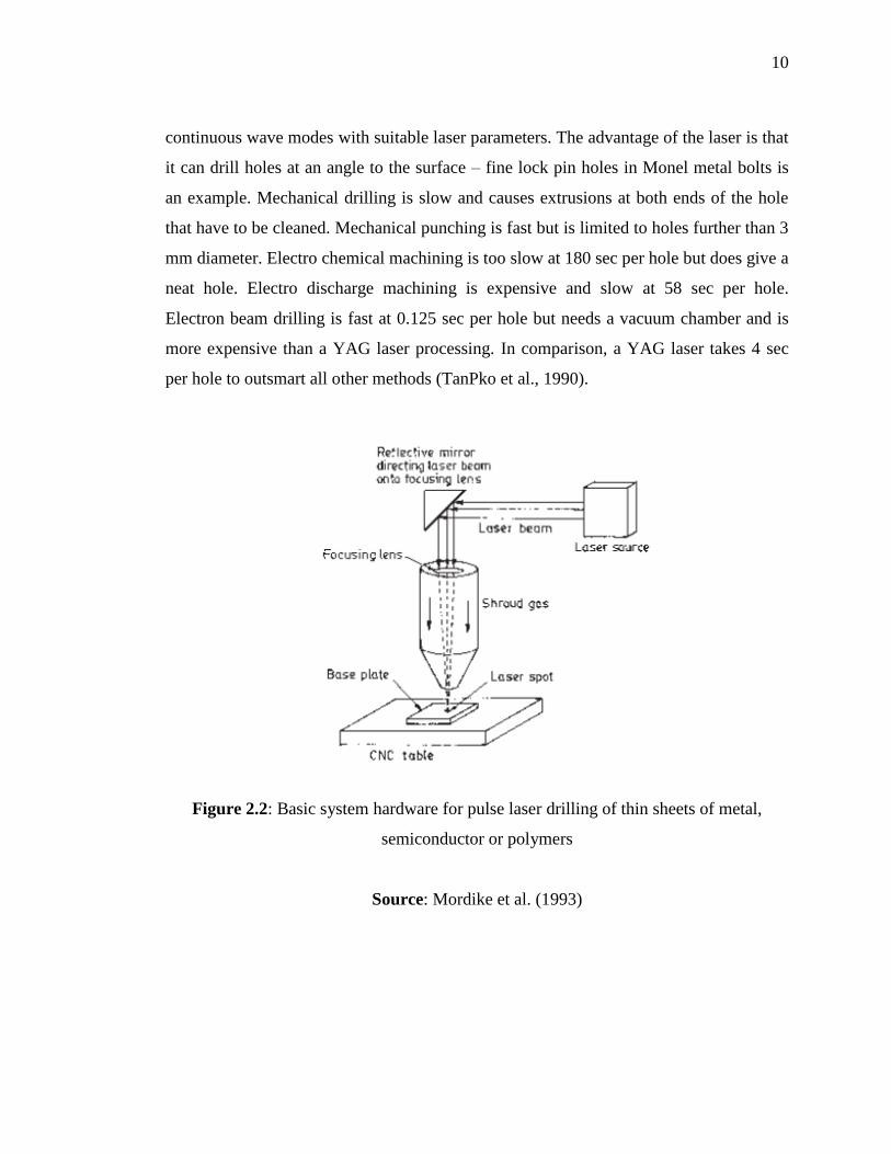
High power CO₂ lasers or Nd: YAG lasers may also be used to drill holes. Figure
2.2 shows the basic set used in laser drilling, which is not very different from that used
for other laser machining processes. Laser drilling can be done in both pulse and
10
continuous wave modes with suitable laser parameters. The advantage of the laser is that
it can drill holes at an angle to the surface – fine lock pin holes in Monel metal bolts is
an example. Mechanical drilling is slow and causes extrusions at both ends of the hole
that have to be cleaned. Mechanical punching is fast but is limited to holes further than 3
mm diameter. Electro chemical machining is too slow at 180 sec per hole but does give a
neat hole. Electro discharge machining is expensive and slow at 58 sec per hole.
Electron beam drilling is fast at 0.125 sec per hole but needs a vacuum chamber and is
more expensive than a YAG laser processing. In comparison, a YAG laser takes 4 sec
per hole to outsmart all other methods (TanPko et al., 1990).
Figure 2.2: Basic system hardware for pulse laser drilling of thin sheets of metal,
semiconductor or polymers
Source: Mordike et al. (1993)

11
2.4.1 Anatomy of Laser Drilling Machine
The laser drilling system used in the experiment is a 100 W pulsed CO₂ laser
with a wavelength of 10.6 mm. Figure 2.3 shows the structure of a CO₂ laser drilling
system, including a CO₂ laser, the optical system (delivery), the feeding system, the
observer system, the base and the control system. The optical system delivers the laser
beam (Fenoughty et al., 1994).
Figure 2.3: Schematic representation of the CO₂ laser drilling system used in
experiment
Source: Chen et al. (2007)
12
The optical system includes a beam shaper (aperture and beam expender) system,
which can improve the quality of the drilling and change the diameter of the holes.
Additionally, the scanning technology can increase the speed of drilling in this optical
system. The laser beam is focused using a lens with a focal length of 80 mm. The focal
plane is positioned on a material surface that is fixed on a vacuum chuck, and the
workpieces are placed on an XY movable table. The table is driven using a linear servo
motor, which has a high positioning accuracy of ±5 μm. In this system, the scanning area
of the scanner is 50 x 50 mm. The focal length of the F-θ lens and the scanning angle of
the scanning mirror lens can be adjusted (Di Ilio et al., 1989).
2.4.2 Laser Types
There are two commonly used laser types in industry today. These are the carbon
dioxide (CO₂) laser and the neodymium yttria-alumina garnet (Nd-YAG) laser, the
former being a gas laser and the latter a solid state laser. CO₂ lasers tend to be high
powered (up to 3 kW) and are used in the continuous-wave mode. The YAG lasers are
used in the pulsed mode and can achieve peak powers of 7-10 kW, although their
average power is of the order of 400 W. The use of these lasers in the pulsed mode
actually enables some cooling of the material being processed during the time interval
between the pulses. The wavelengths of the light sources are different also, CO₂ lasers
having a wavelength of 10.6 μm and YAG a wavelength of 1.06 μm. The wavelength of
the YAG laser is transparent to glass so that it is not an ideal candidate for the cutting of
glass-fibre-reinforced materials (Muller et al., 1989).
There are various factors that have to be taken into account when using lasers as
cutting tools, the main considerations including the absorption of the energy and how
this varies with the temperature of the material, the thermal diffusivity of the material (as
this controls how rapidly the heat is conducted away from the cutting zone) and thirdly
the reaction temperature (of melting / vaporization / decomposition). There are other
considerations such as the dimensions of the heat-affected zone, which is the zone where

13
the capability of stress transfer from the matrix to the fibres is reduced or absent
(Dell'Erba et al., 1992).
A preferred method of cutting carbon composites is with the pulsed YAG laser.
Work done by Lawson (Laser Machining Inc.) on the cutting of graphite, glass and
aramid (Kevlar) composites has shown that 3 mm thick graphite/epoxy can be cut faster
and more cleanly when using a pulsed YAG laser (4 J, 30 pps, 2.5 mm/s speed) than
when using a 5 kW CO₂ laser. A pulsed mode 500 W CO₂ laser has also been tried by
Tagliaferri et al. (Naples/Milan Univ.), who found that a lower specific energies
(power/spot diameter x velocity) a cavity is created due to the rapid vaporization of the
(polyester) resin, which in turn interacts with the fibres, fracturing them into minute
fragments: thus 'cutting' is achieved. At higher energies a keyhole situation occurs due to
the vaporization of the fibres. The conclusion of this work was that a YAG laser should
be used to lower the interaction time whilst maintaining the other parameters, to
optimize the process. The carbon fibres absorb the YAG laser irradiation well and the
high peak powers/short pulses minimize the damage to the matrix. Flaum and Karlsson
(NDRI Sweden) agree with this approach, unless the laminate is thin (less than 2 mm) or
the power is high (greater than 1 kW) (Lawson, 1986).
2.5 CO₂ LASER
Carbon dioxide lasers are being increasingly used in the aircraft and automotive
industries to cut, trim, drill hole and weld sheet metal parts. Compared with other
conventional mechanical processes, laser cutting removes little material, involves highly
localized heat input to the workpiece, minimizes distortion, and offers no tool wear (De
Iorio et al., 1987).