Embed Size (px)
Citation preview
기술논문 Journal of Drive and Control, Vol.12 No.4 pp.77-81 Dec. 2015ISSN(print) 2234-8328 ISSN(online) 2287-6146
http://dx.doi.org/10.7839/ksfc.2015.12.4.077
드라이브 · 컨트롤 2015. 12 77
The Stress Analysis of Planetary Gear System of Mixer Reducer
for Concrete Mixer Truck
Myung Ho Bae1*, Tae Yeol Bae2, Yon Sang Cho3, Ho Yeon Son4 and
Dang Ju Kim4
Received: 18 Oct. 2015, Revised: 23 Nov. 2015, Accepted: 4 Dec. 2015
Key Words:Concrete Mixer Truck, Mixer Reducer, Planetary Gear System, Gear Bending Stress, Gear Compressive
Stress
Abstract: In general, the gears of mixer reducer for concrete mixer truck make use of the differential type planetary
gear system to rotate mixer drum smoothly on the initial conditions. The planetary gear system is very important
part of mixer reducer for concrete mixer truck because of strength problem. In the present study, calculating the gear
specifications and analyzing the gear bending & compressive stresses of the differential planetary gear system for
mixer reducer are necessary to analyze gear bending and compressive stresses confidently, for optimal design of the
planetary gear system in respect to cost and reliability. As a result, analyzing actual gear bending and compressive
stresses of the planetary gear system using Lewes & Hertz equation and verifying the calculated specifications of the
planetary gear system, evaluate the results with the data of allowable bending and compressive stress from the
Stress-No. of cycles curves of gears.
* Corresponding author: [email protected] Dept. of Aviation Maintenance, Changwon Moonsung University, Korea 2 Dept. of Mechatronics, Changwon Moonsung University, Korea3 Dept. of Mechanical Engineering, Dong-A University, Korea 4 DAIHO HYDRAULIC Co., Ltd, Korea
Copyright Ⓒ 2015, KSFCThis is an Open-Access article distributed under the terms of the Creative Commons Attribution Non-Commercial License(http://creativecommons.org/licenses/by-nc/3.0) which permits unrestricted non-commercial use, distribution, and reproduction in any medium, provided the original work is properly cited.
Nomenclatures
Tmi : equivalent mean torque, (N·m)
Nmi : equivalent mean rotating speed, rpm
S : actual gear bending stress, N/mm2
P : actual gear compressive stress, N/mm2
Sab : allowable gear bending stress, N/mm2
Sac : allowable gear compressive stress, N/mm2
1. Introduction
Mixer reducer for concrete mixer truck is driven by a
hydraulic motor, as an important device to rotate the
mixer drum, and to convert the required torque and
rotational speed. Although the increasing initial torque
resulting to the inertia moment increases of output
section, the compound differential type planetary gear
system applies the rotating motion that makes the mixer
drum run smoothly which consists of the sun gear, the
differential planetary gear and two ring gears. Gear
teeth are damaged due to the lack of fatigue strength,
compound planetary gears for mixer and by severe
operating conditions of a concrete mixer truck that have
become a problem.
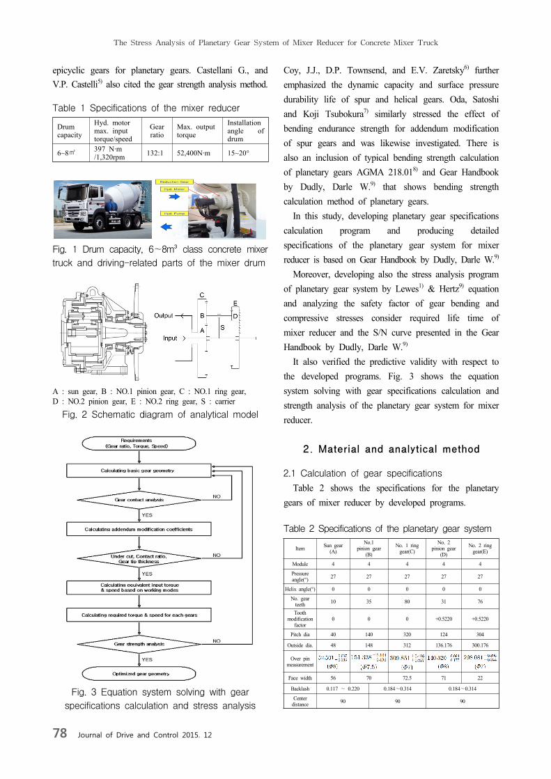
The concrete mixer truck, is shown in Fig. 1, drum
capacity, 6~8m³ class concrete mixer truck. Fig. 2
shows schematic diagram for analytical model of mixer
reducer. Table 1 shows the specifications of the mixer
reducer.
Several investigations have been reported, as cited by
D.E. Imwalle2) “Load equalization in planetary gear
systems”. D.L. Seager3) established load distribution
calculation of the planetary gears. F. Cunliffe, J.D.
Smith and D.B. Welbourn4) Dynamic tooth loads in
The Stress Analysis of Planetary Gear System of Mixer Reducer for Concrete Mixer Truck
78 Journal of Drive and Control 2015. 12
epicyclic gears for planetary gears. Castellani G., and
V.P. Castelli5) also cited the gear strength analysis method.
Table 1 Specifications of the mixer reducer
Drumcapacity
Hyd. motormax. input torque/speed
Gear ratio
Max. outputtorque
Installationangle of drum
6~8㎥397 N·m /1,320rpm 132:1 52,400N·m 15~20°
Fig. 1 Drum capacity, 6~8m³ class concrete mixer
truck and driving-related parts of the mixer drum
A : sun gear, B : NO.1 pinion gear, C : NO.1 ring gear,D : NO.2 pinion gear, E : NO.2 ring gear, S : carrier
Fig. 2 Schematic diagram of analytical model
Fig. 3 Equation system solving with gear
specifications calculation and stress analysis
Coy, J.J., D.P. Townsend, and E.V. Zaretsky6) further
emphasized the dynamic capacity and surface pressure
durability life of spur and helical gears. Oda, Satoshi
and Koji Tsubokura7) similarly stressed the effect of
bending endurance strength for addendum modification
of spur gears and was likewise investigated. There is
also an inclusion of typical bending strength calculation
of planetary gears AGMA 218.018) and Gear Handbook
by Dudly, Darle W.9) that shows bending strength
calculation method of planetary gears.
In this study, developing planetary gear specifications
calculation program and producing detailed
specifications of the planetary gear system for mixer
reducer is based on Gear Handbook by Dudly, Darle W.9)
Moreover, developing also the stress analysis program
of planetary gear system by Lewes1) & Hertz9) equation
and analyzing the safety factor of gear bending and
compressive stresses consider required life time of
mixer reducer and the S/N curve presented in the Gear
Handbook by Dudly, Darle W.9)
It also verified the predictive validity with respect to
the developed programs. Fig. 3 shows the equation
system solving with gear specifications calculation and
strength analysis of the planetary gear system for mixer
reducer.
2. Material and analytical method
2.1 Calculation of gear specifications
Table 2 shows the specifications for the planetary
gears of mixer reducer by developed programs.
Table 2 Specifications of the planetary gear system
Item Sun gear(A)
No.1 pinion gear
(B)
No. 1 ring gear(C)
No. 2 pinion gear
(D)
No. 2 ring gear(E)
Module 4 4 4 4 4
Pressure angle(°) 27 27 27 27 27
Helix angle(°) 0 0 0 0 0
No. gear teeth 10 35 80 31 76
Tooth modification
factor0 0 0 +0.5220 +0.5220
Pitch dia 40 140 320 124 304
Outside dia. 48 148 312 136.176 300.176
Over pin measurement
Face width 56 70 72.5 71 22
Backlash 0.117 ~ 0.220 0.184~0.314 0.184~0.314
Center distance 90 90 90
Myung Ho Bae, Tae Yeol Bae, Yon Sang Cho, Ho Yeon Son and Dang Ju Kim
드라이브 · 컨트롤 2015. 12 79
(1)
Workingmode
Frequency of use(%)
Working time(h)
InputDuty cycle Cycle ratioTorque
(N∙m) Speed(rpm)
Input concrete 4 1,136 189.9 1320 89971200 0.125391849
Driving 41 11,644 189.9 264 184440960 0.257053291
Normal working 12 3,408 241.7 660 134956800 0.188087774
Maximum working 1 284 284.8 132 2249280 0.003134796
Driving 38 10,792 52.4 264 170945280 0.238244514
Washing 4 1,136 52.4 1980 134956800 0.188087774
Total 100 28,400 - - 717,520,320 1
(2)
(3)
(4)
(5)
(6)
(7)
(8)
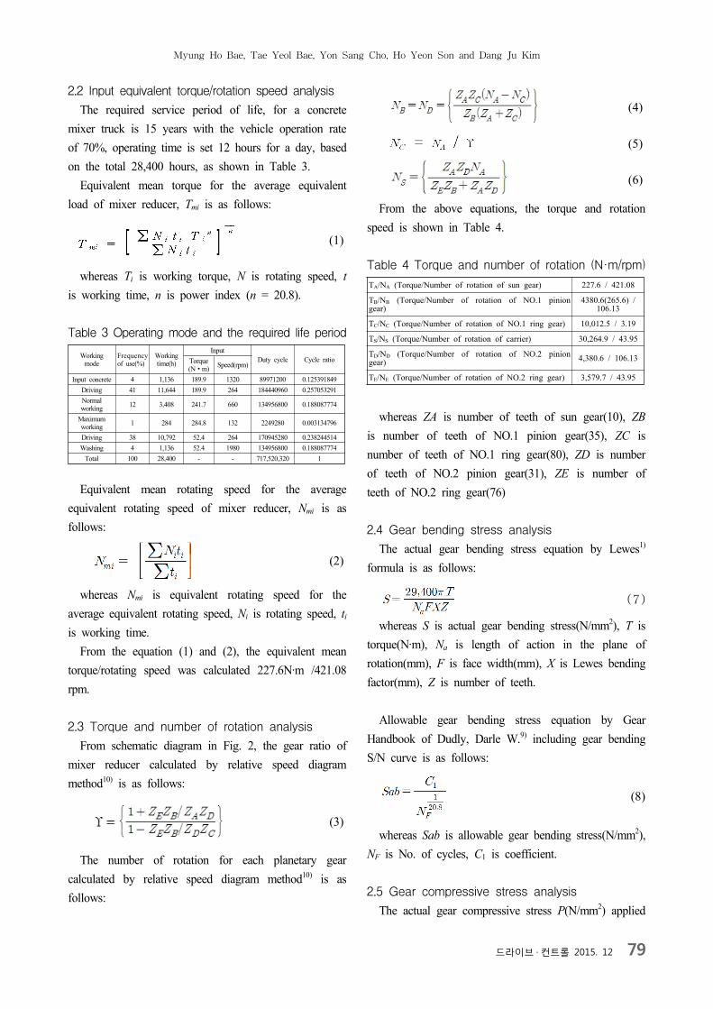
2.2 Input equivalent torque/rotation speed analysis
The required service period of life, for a concrete
mixer truck is 15 years with the vehicle operation rate
of 70%, operating time is set 12 hours for a day, based
on the total 28,400 hours, as shown in Table 3.
Equivalent mean torque for the average equivalent
load of mixer reducer, Tmi is as follows:
whereas Ti is working torque, N is rotating speed, t is working time, n is power index (n = 20.8).
Table 3 Operating mode and the required life period
Equivalent mean rotating speed for the average
equivalent rotating speed of mixer reducer, Nmi is as
follows:
whereas Nmi is equivalent rotating speed for the
average equivalent rotating speed, Ni is rotating speed, ti is working time.
From the equation (1) and (2), the equivalent mean
torque/rotating speed was calculated 227.6N·m /421.08
rpm.
2.3 Torque and number of rotation analysis
From schematic diagram in Fig. 2, the gear ratio of
mixer reducer calculated by relative speed diagram
method10) is as follows:
The number of rotation for each planetary gear
calculated by relative speed diagram method10) is as
follows:
From the above equations, the torque and rotation
speed is shown in Table 4.
Table 4 Torque and number of rotation (N·m/rpm)
TA/NA (Torque/Number of rotation of sun gear) 227.6 / 421.08
TB/NB (Torque/Number of rotation of NO.1 pinion gear)
4380.6(265.6) / 106.13
TC/NC (Torque/Number of rotation of NO.1 ring gear) 10,012.5 / 3.19
TS/NS (Torque/Number of rotation of carrier) 30,264.9 / 43.95
TD/ND (Torque/Number of rotation of NO.2 pinion gear) 4,380.6 / 106.13
TE/NE (Torque/Number of rotation of NO.2 ring gear) 3,579.7 / 43.95
whereas ZA is number of teeth of sun gear(10), ZB
is number of teeth of NO.1 pinion gear(35), ZC is
number of teeth of NO.1 ring gear(80), ZD is number
of teeth of NO.2 pinion gear(31), ZE is number of
teeth of NO.2 ring gear(76)
2.4 Gear bending stress analysis
The actual gear bending stress equation by Lewes1)
formula is as follows:
whereas S is actual gear bending stress(N/mm2), T is
torque(N·m), Na is length of action in the plane of
rotation(mm), F is face width(mm), X is Lewes bending
factor(mm), Z is number of teeth.
Allowable gear bending stress equation by Gear
Handbook of Dudly, Darle W.9) including gear bending
S/N curve is as follows:
whereas Sab is allowable gear bending stress(N/mm2),
NF is No. of cycles, C1 is coefficient.
2.5 Gear compressive stress analysis
The actual gear compressive stress P(N/mm2) applied
The Stress Analysis of Planetary Gear System of Mixer Reducer for Concrete Mixer Truck
80 Journal of Drive and Control 2015. 12
(9)
(10)
to the tip of the planetary gears based on contact
formula of Hertz9) is as follows:
whereas α is normal pressure angle, Φ is transverse
pressure angle, T is torque on driving gear(N·m), Fc is
active face width in contact(mm), Z is No. of teeth on
driving gear, CD is operating center distance, Na is
length of action in the plane of rotation(mm), A =
, OR is outside radius of gear, BR is base
radius of gear.
Allowable gear compressive stress equation by Gear
Handbook of Dudly, Darle W.9) including gear
compressive S/N curve is as follows:
whereas Sac is allowable gear compressive
stress(N/mm2), NF is No. of cycles, C2 is coefficient.
2.6 The results of gear bending and compressive
stress analysis
Calculating actual gear bending and compressive
stresses of planetary gear system for mixer reducer and
considering allowable gear bending and compressive
stresses, produce safety factors and verify the problems
of gear strength for the calculated specifications of the
planetary gear system for mixer reducer.
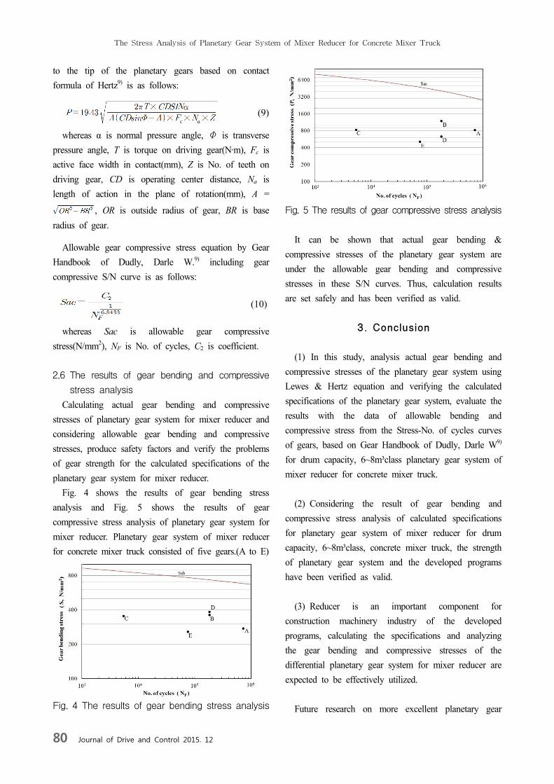
Fig. 4 shows the results of gear bending stress
analysis and Fig. 5 shows the results of gear
compressive stress analysis of planetary gear system for
mixer reducer. Planetary gear system of mixer reducer
for concrete mixer truck consisted of five gears.(A to E)
Fig. 4 The results of gear bending stress analysis
Fig. 5 The results of gear compressive stress analysis
It can be shown that actual gear bending &
compressive stresses of the planetary gear system are
under the allowable gear bending and compressive
stresses in these S/N curves. Thus, calculation results
are set safely and has been verified as valid.
3. Conclusion
(1) In this study, analysis actual gear bending and
compressive stresses of the planetary gear system using
Lewes & Hertz equation and verifying the calculated
specifications of the planetary gear system, evaluate the
results with the data of allowable bending and
compressive stress from the Stress-No. of cycles curves
of gears, based on Gear Handbook of Dudly, Darle W9)
for drum capacity, 6~8m³class planetary gear system of
mixer reducer for concrete mixer truck.
(2) Considering the result of gear bending and
compressive stress analysis of calculated specifications
for planetary gear system of mixer reducer for drum
capacity, 6~8m³class, concrete mixer truck, the strength
of planetary gear system and the developed programs
have been verified as valid.
(3) Reducer is an important component for
construction machinery industry of the developed
programs, calculating the specifications and analyzing
the gear bending and compressive stresses of the
differential planetary gear system for mixer reducer are
expected to be effectively utilized.
Future research on more excellent planetary gear
Myung Ho Bae, Tae Yeol Bae, Yon Sang Cho, Ho Yeon Son and Dang Ju Kim
드라이브 · 컨트롤 2015. 12 81
system of the various reducers for construction
machines is expected to be still performed.
Acknowledgement
This work was supported by the Ministry of Trade,
Industry & Energy,(project number ; A010600035, A
development of mixer drum driving unit for 6 ~ 8
Lube grade concrete mixer truck) and the authors are
gratefully appreciative of the support.
References
1) Lewes, Wilfred, “Investigation of Strength of Gear
Teeth,” Proc. Eng. Club, Philadelphia, pp. 38-55,
1893.
2) D. E. Imwalle, “Load Equalization in Planetary
Gear Systems,” ASME publication at the
Mechanisms Conference & International Symposium
on Gearing and Transmissions, pp. 232-238, 1972
3) D. L. Seager, “Load Sharing among Planet Gears,”
SAE publication No. 700178, pp. 651-656, 1972
4) F. Cunliffe, J. D. Smith and D. B. Welbourn,
“Dynamic Tooth Loads in Epicyclic Gears,”
Transactions of the ASME Journal of Engineering
for Industry, pp. 578-584, 1974.
5) Castellani G., and V. P. Castelli, “Rating Gear
Strength,” ASME Paper No. 80-C2/DET-88, pp.
37-43, 1980.
6) Coy, J. J., D. P. Townsend, and E. V. Zaretsky,
“Dynamic Capacity and Surface Fatigue Life for
Spur and Helical Gears,” ASME Paper No.
75-Lub-19, pp. 56-73, 1975.
7) Oda, Satoshi and Koji Tsubokura, “Effects of
Addendum Modification on Bending Fatigue
Strength of Spur Gears(3rd Report, Cast Iron and
Cast Steel Gears),” Bull. JSME, Vol. 24, No. 190,
Paper No. 190-15, April, pp. 24-30, 1981.
8) AGMA Standard 218.01, “The Pitting Resistance
and Bending Strength of Spur and Helical Involute
Gear Teeth,” The American Gear Manufacturers
Association, pp. 14-20, 1982.
9) D.W. Dudley, The Handbook of Practical Gear
Design, 2nd Edition, Mcgraw-Hill, pp. 1.27-1.32,
2.1-2.12, 3.1-3.45, 3.78-3.112, 1984.
10) M. H. Bae, S. K. Jang and S. Y. Lee. Automotive
& Continuously Variable Transmission, 2nd Edition,
Sun Hak publication, pp. 37-44, 2009.


![[5] Planetary gear and Mechanical paradox Gear design ...Eng).pdf · 1 [5] Planetary gear and Mechanical paradox Gear design system (English Version) Fig.5.1 Planetary gear and Mechanical](https://img.pdfslide.us/doc/110x75/5a78d0067f8b9aa17b8cf015/5-planetary-gear-and-mechanical-paradox-gear-design-engpdf1-5-planetary.jpg)