Embed Size (px)
Citation preview
The Stock Clock: A ZigBee Project. 1 of 23
The Stock Clock
A Sample ZigBee Implementation
Richard Hoptroff
Feature article submission to Circuit Cellar
2300 words, 2 listings (70 lines), 5 figures
Second draft
All text and figures available in electronic format
The Stock Clock: A ZigBee Project. 2 of 23
The Stock Clock
A Sample ZigBee Implementation
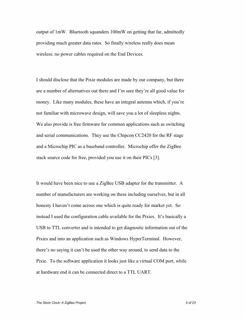
Last Christmas, yet another family member got one of those weather stations
where there’s a thermometer on a radio link so you can tell the temperature
outside without actually having to get out of your armchair. It’s sort of neat,
said the techie voice inside me, but this is the internet age. Why can’t it tell
me tomorrow’s weather forecast or the latest stock prices? Well let’s have a
go.
Figure 1 shows the basic idea of the Stock Clock. A PC automatically goes to
a web page and picks up the stock price, weather forecast or whatever. It then
sends this information to a ZigBee Coordinator connected to the USB port.
This sends the data to a remote ZigBee End Device, which displays it on a dial
using a stepper motor. The project divides up into three parts: the PC
software, the Coordinator and the End Device.

The Stock Clock: A ZigBee Project. 3 of 23
PC Software
The PC software was the easy bit. Back in the heady days when the Nasdaq
was topping 5000, our company had the crazy idea of making an LCD ticker-
tape product. It would pull the latest news, financial and weather data off the
internet and transmit it to a fridge-mounted LCD display. (Attached with a
magnet, of course.) I don’t know what we were thinking of. The batteries on
the display wouldn’t have lasted more than a week, and the project was
looking like it was going to run way over-budget from the day it started.
Needless to say the prototype was last seen gathering dust on a shelf,
sometime before we moved office.
Six years on, I realized that the software part would be just right for the Stock
Clock. I finally tracked down the last remaining copy, lurking on the hard
disk of a desktop we let our cleaning lady take home some time back. Teasing
the files off a PC with nothing but a floppy drive was like trying to breathe life
back to a dinosaur. Anyhow, I got there in the end.
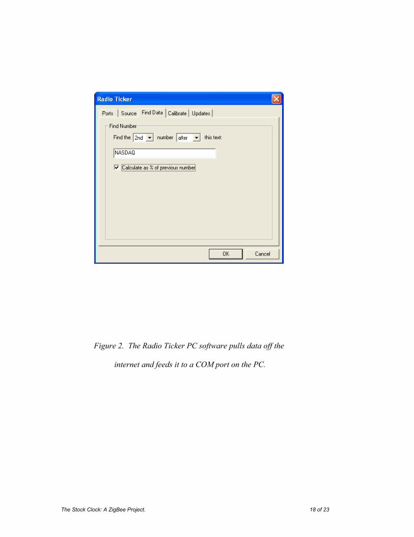
It’s actually quite a neat application program and hardly required any
modification for this project. It sits as a green icon in your PC’s system tray,
looks up a web page every now and then, scrubs it for the required
information and then transmits data to a COM port. Double-clicking on the
system tray icon brings up the configuration screen (figure 2). I set it up to

The Stock Clock: A ZigBee Project. 4 of 23
read my.yahoo.com which I have personalized to contain lots of information
of interest to me – weather forecasts, stock prices, whether I have mail, etc.
How it actually gets the data off the internet is beyond the scope of this article
but this is discussed in depth in [1].
ZigBee Coordinator
Next step was the ZigBee Coordinator node, which is attached to the PC. I
chose ZigBee for a number of reasons [2]. The first was low cost. A number
of vendors give away their ZigBee stacks for free, so you can put your
application on the same microcontroller that’s running the ZigBee stack. This
makes life a little more complicated than using a dedicated ZigBee modem
with AT commands, but it keeps the overall costs down. The second reason
for choosing ZigBee was interoperability. The guys in the ZigBee Alliance
reckon we’ll all soon be using ZigBee to turn the lights on and off in our
homes. So you’ll have a ZigBee mesh network in your house and could
piggyback on it to send a signal anywhere you want, even if the mesh is
cobbled together with parts from a mix of manufacturers.
The third reason for choosing ZigBee was low power. The Direct Sequence
Spread Spectrum modulation system it uses gives it an inherent 12dB
advantage over other systems such as Bluetooth. The Pixie devices I’ll be
using for this project have a range of around 500 feet with an output power
The Stock Clock: A ZigBee Project. 5 of 23
output of 1mW. Bluetooth squanders 100mW on getting that far, admittedly
providing much greater data rates. So finally wireless really does mean
wireless: no power cables required on the End Devices.
I should disclose that the Pixie modules are made by our company, but there
are a number of alternatives out there and I’m sure they’re all good value for
money. Like many modules, these have an integral antenna which, if you’re
not familiar with microwave design, will save you a lot of sleepless nights.
We also provide is free firmware for common applications such as switching
and serial communications. They use the Chipcon CC2420 for the RF stage
and a Microchip PIC as a baseband controller. Microchip offer the ZigBee
stack source code for free, provided you use it on their PICs [3].
It would have been nice to use a ZigBee USB adapter for the transmitter. A
number of manufacturers are working on these including ourselves, but in all
honesty I haven’t come across one which is quite ready for market yet. So
instead I used the configuration cable available for the Pixies. It’s basically a
USB to TTL converter and is intended to get diagnostic information out of the
Pixies and into an application such as Windows HyperTerminal. However,
there’s no saying it can’t be used the other way around, to send data to the
Pixie. To the software application it looks just like a virtual COM port, while
at hardware end it can be connected direct to a TTL UART.
The Stock Clock: A ZigBee Project. 6 of 23
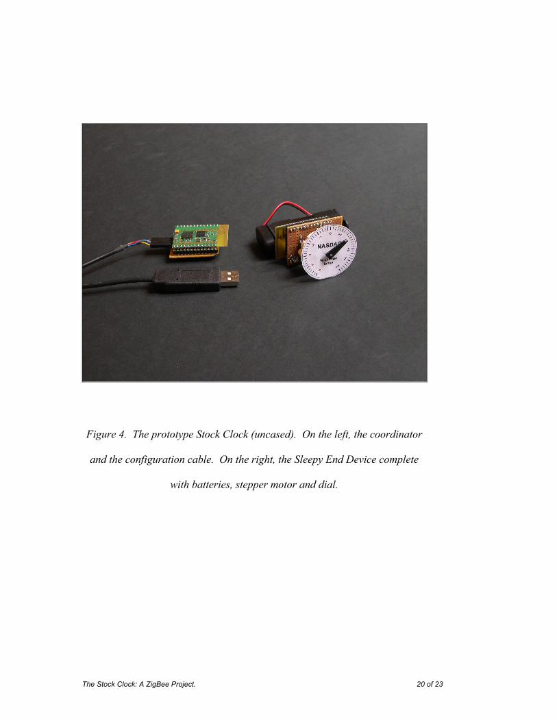
The circuit diagram is shown in figure 3, and the working prototype in figure
4. (We were running to a deadline to get in this Wireless Communications
special issue, so I didn’t have time to lay it out on an etched PCB.) The
configuration cable has a handy 5V, 50mA power source which can be used to
power the 3.3V circuit via voltage regulator VR1.
To convert between the 5V TTL levels of the configuration tool and the 3.3V
levels of the Pixie, R1 limits the incoming current to around 300µA while the
I/O protection diodes inside the PIC clamp the voltage to 3.3V. In the other
direction, just a straight through connection is needed as 3.3V is, in TTL terms,
considered logic 1.
Sleepy End Device
The remote dial pointer is battery powered, so in ZigBee terms it is a Sleepy
End Device. Every 2 minutes, it wakes up to check in with the Coordinator to
see if its dial indication has changed. It then adjusts the dial if required, and
falls back asleep again. The 2µA consumption during sleep is negligible, so
supposing it wakes for an average 100ms each time, and consumes 30mA
while awake, that equates to a 5 year battery life with standard 1100mAh
‘AA’ batteries. So there is legitimacy to the claim that battery power is
possible with ZigBee.

The Stock Clock: A ZigBee Project. 7 of 23
The Pixie will work on any supply voltage from 2.1V to 3.3V, so it can be
connected direct to the 2 AA cells. The stepper motor driving the dial pointer
is a 2-coil Switec XC-5 [4], which grinds to a halt at around 2.3V, so that’s
the limiting power factor. The Switecs are widely used in the automotive
industry for dashboard dials, but any similar stepper motor with the same
stepper sequencing pattern (figure 5) and coil currents of 30mA or less could
be used in its place. Note that the I/O protection diodes in the PIC protect it
from any back-EMF generated by the motor coils. Bear this in mind if you try
this with any other microcontrollers.
Pushbutton PB1 is just to nudge the dial pointer around once the dial is in its
enclosure, since it will forget which way it is pointing if the batteries are
removed.
ZigBee Red Tape
The price paid for mesh networking is that ZigBee adds a lot of bureaucratic
overhead to every packet it transmits. The physical layer adds 6 bytes so that
receivers can recognize it’s an IEEE 802.15.4 standard packet [5]. The MAC
layer adds between 3 and 23 bytes to say who is transmitting and who is
supposed to be receiving. It also adds 2-byte frame check-sum (FCS) at the
end. The 8-byte NWK header controls multi-hop communication over the
mesh and says where the packet originated from and where it’s supposed to
The Stock Clock: A ZigBee Project. 8 of 23
get routed to [6]. The APS/AF adds another 5-7 bytes to indicate what kind of
data is in the packet. This is known as the ZigBee profile and provides
interoperability between manufacturers so, for example, one man’s light
switch will work with another man’s light. Finally, the packet data is
transmitted, which in our case will be a single byte that indicates the required
angle of the pointer on the dial.
The Microchip ZigBee Stack has come on a long way since Fred Eady
reported on it last year and the latest release (1.0-3.5) does a lot get around all
this red tape. By the time this gets to press, we hope to be providing an
additional API wrapper called Pixie MailBox which will turns many common
tasks into #defines and adds a few extra features such as a fixed addressing
system and runtime-definable device types.
This project simply modifies the Home Controls – Lighting (HC-L) demo
provided with the stack. We could have defined our own Stock Clock profile,
but this way we could have some fun trying to bind the dial to light switch
products, too. The coordinator will pretend it is a switch and the dial will
pretend it is a light. The HC-L profile defines only byte messages 0x00 (off),
0xF0 (toggle) and 0xFF (on) for switching, but we accept any message,
interpreting it as the desired pointer angle, in multiples of two degrees.
The Stock Clock: A ZigBee Project. 9 of 23
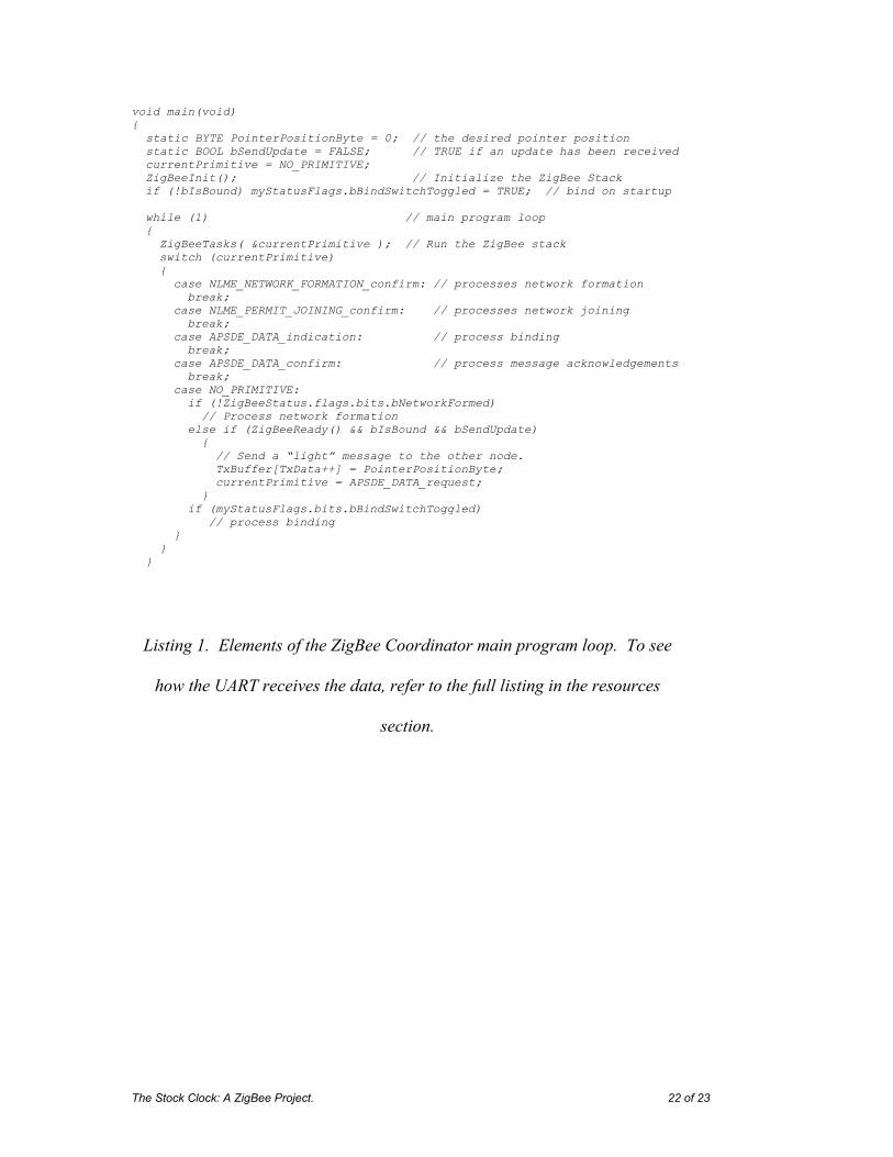
Listing 1 shows extracts of the C code for the Coordinator. Note the form of
the program. It is a finite state machine and the current status of the stack is
known as the current primitive. The first thing the coordinator does when it
initializes is choose a free channel to operate on using the
NLME_NETWORK_FORMATION_confirm primitive. Then it waits for other
devices to join the network.
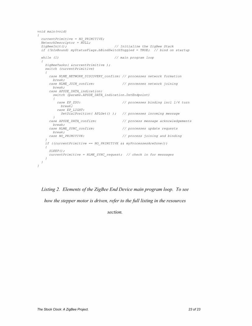
Listing 2 shows the C code for the Sleepy End Device. When it first
initializes, it locates the coordinator and joins the network. Then it
immediately asks the coordinator to bind its “light” dial indicator to the
coordinator’s “switch” pointer controller logic. For this to work, they must be
turned on at the same time the first time they are used. If binding is successful,
the pointer celebrates by swinging a quarter turn. Once the two are bound,
they stay bound so this process does not need to be repeated. In theory, there
could be a string of routers between the coordinator and the end device, but I
haven’t tried that out yet.
The Radio Ticker software monitors the internet to get the required dial
pointer value and sends it as a byte to the coordinator. It should not send a
byte more frequently than the End Device wakes up, otherwise a backlog of
messages will build up.
The Stock Clock: A ZigBee Project. 10 of 23
The coordinator monitors the incoming data to see if the dial reading needs
changing. If it does, it sends the end device a message using the
APSDE_DATA_request primitive. Actually, the message gets pigeon-holed
somewhere in the recesses of the coordinator until the end device wakes up
and asks for it.
The End Device wakes every two minutes and uses the NLME_SYNC_request
primitive to ask the Coordinator whether any messages are waiting for it. If
there is a message, it is received through the APSDE_DATA_indication
primitive and the pointer value is updated.
Hot-off-the-press data
Finally I had to decide what to display on the dial. The weather forecast
turned out to be a bit unexciting because it doesn’t update more than two or
three times a day. Stock prices are much more fun, changing unpredictably by
the minute. And face it, it’s more interesting to know if you’re getting richer
or poorer than if you’re going to need an umbrella tomorrow.
I’ve had the Stock Clock around the house for a few days now and I’ve
quickly become used to it. My interest in it is now much more for the
information it conveys than the technology it uses. So it passes the Hoptroff

The Stock Clock: A ZigBee Project. 11 of 23
customer satisfaction test. Actually sometimes I want to throw it against the
wall when it’s go bad news for me. Talk about shooting the messenger.
The Stock Clock: A ZigBee Project. 12 of 23
About the author
Richard Hoptroff is a development engineer for FlexiPanel Ltd of London,
UK, and co-author of Data Mining and Business Intelligence: A Guide to
Productivity. He holds a PhD in Physics from London University and his
interests include travel, travel and more travel. He may be contacted at
The Stock Clock: A ZigBee Project. 13 of 23
Project Files
StockClockCoordinator.c coordinator C source code, replaces the Coordinator.c file in the Microchip Stack demo application.
StockClockPointer.c end device C source code, replaces the RFD.c file in the Microchip Stack demo application.
StockClockCoordinator.c precompiled hex code for Pixie.
StockClockPointer.hex precompiled hex code for Pixie.
RadioTicker.exe internet scrubbing application

The Stock Clock: A ZigBee Project. 14 of 23
Resources
Pixie DS481-9.pdf documentation
ReadMe.txt accompanying notes
The Stock Clock: A ZigBee Project. 15 of 23
References
[1] Programming Bots, Spiders and Intelligent Agents in Visual C++, David Pallmann, Microsoft Press 1999.
[2] ZigBee for Applications Developers, Richard Hoptroff downloadable from www.flexipanel.com/DownloadsIndex.htm
[3] AN965 Microchip Stack for ZigBee Protocol, Nilesh Rajbharti, downloadable from www.microchip.com.
[4] XC5 Specification downloadable from www.microcomponents.ch
[5] IEEE Standard 802.15.4 - 2003 downloadable from ieeexplore.ieee.org/xpl/standards.jsp
[6] ZigBee Specification, downloadable from www.zigbee.org.

The Stock Clock: A ZigBee Project. 16 of 23
Sources
Pixie distributor:
(Will ship to the USA)
R F Solutions Ltd Unit 21, Cliffe Industrial Estate, Lewes, E. Sussex BN8 6JL, United Kingdom email: [email protected] http://www.rfsolutions.co.uk Tel: +44 (0)1273 898 000, Fax: +44 (0)1273 480 661
MPLAB and C18 development tools:
Microchip Technlogy Inc 2355 W Chandler Blvd Chandler, AZ 85224-6199, USA http://www.microchip.com

The Stock Clock: A ZigBee Project. 17 of 23
Internetconnection
PCZigBeeCoordinator
ZigBeeEnd Device
Stepper motorand display dial
Battery power
Figure 1. Basic setup of the Stock Clock.
The Stock Clock: A ZigBee Project. 18 of 23
Figure 2. The Radio Ticker PC software pulls data off the
internet and feeds it to a COM port on the PC.

The Stock Clock: A ZigBee Project. 19 of 23
Pixiemodule
Onboardantenna
VR1
C2C1
VinLM1117T-3.3
Gnd
R1Tx (red)
Rx (blue)
Gnd (black)
5V (yellow)
C1 = 1uFC2 = 100nFR1,R2 = 4k7To USB to
TTL adapter
VoutVdd, NRST
Gnd
RxD
TxD
Pixiemodule
Onboardantenna
Vdd, NRST
Gnd
2 x AACell
R2
PB1
M1RB5
12
3 4
RA1
RA2
RA3
RA4
Figure 3. Schematics for the Coordinator (top) and
the Sleepy End Device (bottom).
The Stock Clock: A ZigBee Project. 20 of 23
Figure 4. The prototype Stock Clock (uncased). On the left, the coordinator
and the configuration cable. On the right, the Sleepy End Device complete
with batteries, stepper motor and dial.

The Stock Clock: A ZigBee Project. 21 of 23
Contact 1
Contact 2, 3
clockwise
1
0
1
0
1
0
counterclockwise
Contact 4
Figure 5. Two cycles of the stepper motor sequence.
180 cycles are required for a full rotation of the pointer dial.
The Stock Clock: A ZigBee Project. 22 of 23
void main(void) {
static BYTE PointerPositionByte = 0; // the desired pointer position static BOOL bSendUpdate = FALSE; // TRUE if an update has been received
currentPrimitive = NO_PRIMITIVE; ZigBeeInit(); // Initialize the ZigBee Stack if (!bIsBound) myStatusFlags.bBindSwitchToggled = TRUE; // bind on startup while (1) // main program loop { ZigBeeTasks( ¤tPrimitive ); // Run the ZigBee stack switch (currentPrimitive) { case NLME_NETWORK_FORMATION_confirm: // processes network formation break; case NLME_PERMIT_JOINING_confirm: // processes network joining break; case APSDE_DATA_indication: // process binding break; case APSDE_DATA_confirm: // process message acknowledgements break; case NO_PRIMITIVE: if (!ZigBeeStatus.flags.bits.bNetworkFormed) // Process network formation else if (ZigBeeReady() && bIsBound && bSendUpdate) { // Send a “light” message to the other node. TxBuffer[TxData++] = PointerPositionByte; currentPrimitive = APSDE_DATA_request; } if (myStatusFlags.bits.bBindSwitchToggled) // process binding } } }
Listing 1. Elements of the ZigBee Coordinator main program loop. To see
how the UART receives the data, refer to the full listing in the resources
section.
The Stock Clock: A ZigBee Project. 23 of 23
void main(void) { currentPrimitive = NO_PRIMITIVE; NetworkDescriptor = NULL; ZigBeeInit(); // Initialize the ZigBee Stack if (!bIsBound) myStatusFlags.bBindSwitchToggled = TRUE; // bind on startup while (1) // main program loop { ZigBeeTasks( ¤tPrimitive ); switch (currentPrimitive) { case NLME_NETWORK_DISCOVERY_confirm: // processes network formation break; case NLME_JOIN_confirm: // processes network joining break; case APSDE_DATA_indication: switch (params.APSDE_DATA_indication.DstEndpoint) { case EP_ZDO: // processes binding incl 1/4 turn break; case EP_LIGHT: SetDialPosition( APLGet() ); // processes incoming message } case APSDE_DATA_confirm: // process message acknowledgements break; case NLME_SYNC_confirm: // processes update requests break; case NO_PRIMITIVE: // process joining and binding } if ((currentPrimitive == NO_PRIMITIVE && myProcessesAreDone()) { SLEEP(); currentPrimitive = NLME_SYNC_request; // check in for messages } } }
Listing 2. Elements of the ZigBee End Device main program loop. To see
how the stepper motor is driven, refer to the full listing in the resources
section.