Embed Size (px)
Citation preview
University of Alberta
The stimulus router system: A novel neural prosthesis
by
Liu Shi Gan
A thesis submitted to the Faculty of Graduate Studies and Research in partial fulfillment of the requirements for the degree of
Doctor of Philosophy
Medical Sciences – Biomedical Engineering
©Liu Shi Gan Fall 2009
Edmonton, Alberta
Permission is hereby granted to the University of Alberta Libraries to reproduce single copies of this thesis and to lend or sell such copies for private, scholarly or scientific research purposes only. Where the thesis is
converted to, or otherwise made available in digital form, the University of Alberta will advise potential users of the thesis of these terms.
The author reserves all other publication and other rights in association with the copyright in the thesis and,
except as herein before provided, neither the thesis nor any substantial portion thereof may be printed or otherwise reproduced in any material form whatsoever without the author's prior written permission.

Examining Committee Dr. Arthur Prochazka, Department of Physiology Dr. K. Ming Chan, Division of Physical Medicine and Rehabilitation Dr. Richard Stein, Department of Physiology Dr. David Collins, Faculty of Physical Education and Recreation Dr. Edmond Lou, Department of Biomedical Engineering Dr. Gerald Loeb, Department of Biomedical Engineering, University of Southern California
Abstract
Neural prostheses (NPs) are electronic stimulators that activate nerves to
restore sensory or motor functions. Surface NPs are non-invasive and
inexpensive, but are often poorly selective, activating non-targeted muscles and
cutaneous sensory nerves that can cause pain or discomfort. Implanted NPs are
highly selective, but invasive and costly. The stimulus router system (SRS) is a
novel NP consisting of fully implanted leads that “capture” and route some of the
current flowing between a pair of surface electrodes to the vicinity of a target
nerve. One end of an SRS lead has a “pick-up” terminal that is implanted
subcutaneously under the location of a surface electrode and the other end has a
“delivery” terminal that is secured on or near the target nerve.
The studies presented in this thesis address the development of the SRS
from animal testing to its implementation as an upper extremity NP in a
tetraplegic subject. Chapters 2 and 3 describe the SRS’s basic properties, provide
proof-of-principle of the system in animal studies and identify aspects that
maximize its performance as a motor NP. The studies showed that selective and
graded activation of deep-lying nerves can be achieved with the SRS over the full
physiological range. Long term reliability of the system was demonstrated in
chronic animal studies. The surface current needed to activate nerves with a SRS
was found to depend on the proximity of the delivery terminal(s) to the target
nerve, contact areas of the surface electrodes and implanted terminals, electrode
configuration and the distances from the surface anode to the surface cathode and
delivery terminal. Chapter 4 describes the first human proof-of-principle of the
SRS during an intra-operative test. Finally, Chapter 5 describes the
implementation of the SRS for restoration of hand function in a tetraplegic
subject. Stimulation parameters and force elicited through the SRS, along with
usage of the device were monitored up to 10 months after implantation. The
system was found to be useful, reliable and robust. It is argued that the results of
these studies indicate that the SRS provides the basis for a new family of NPs.

Acknowledgements
I would like to express my deepest thanks to my supervisor, Dr. Arthur
Prochazka, for the opportunity to work in his laboratory and for his guidance,
patience, support and ideas throughout my Ph.D. training. I would also like to
thank my committee members, Drs. Ming Chan, Vivian Mushahwar and Richard
Stein, for their time, comments and suggestions, and to my examination
committee for their time and effort. Thanks to Dr. Gerald Loeb for being the
external examiner for my defense.
I am grateful to members of the Prochazka lab for their assistance and
input. Thanks to Michel Gauthier and Al Denington for their technical support.
Thanks to Robert Gaunt and Jan Kowalcheszki for sharing their ideas and
experience. Thanks to Tyler Simpson and Natalie Ravid for always being willing
to help. Also, I would like to thank my friends and colleagues on the 5th floor of
HMRC, for making a great work environment. Special thanks to Dirk Everaert
and Esther Udina for their encouragement and friendship.
I am also grateful to my friends in Edmonton and Malaysia for being there
for me whenever I needed. Special thanks to Carol Boliek and Karen Wei for their
support during the final stages of writing this thesis. Finally, and most
importantly, I would like to thank my family for their support and understanding.
Thank you to my parents for their encouragement and to my brother for always
caring.

I would like to acknowledge the Alberta Heritage Foundation and the
Canadian Institute of Health Research for their financial support during the period
of this degree.
Table of Contents
Chapter 1 1
Introduction 1
1.1 General introduction 1 1.2 Brief history 3 1.3 Principles of functional electrical stimulation 4
1.3.1 Properties of extracellular stimulation 5 1.3.1.1 Effect of electrode polarity on activation thresholds 6 1.3.1.2 Discrete cable model for myelinated axons 7 1.3.1.3 Effect of axon diameter on activation threshold 9 1.3.1.4 Effect of axon-electrode distance on activation threshold 9 1.3.1.5 Strength-duration curve 9
1.3.2 Electrochemistry at electrode tissue interface 10 1.3.3 Muscle activation 12
1.3.3.1 Reverse recruitment order 12 1.3.3.2 Force modulation 13 1.3.3.3 Muscle fatigue 13
1.4 Limitations of FES for restoration of motor function 15 1.5 Motor prosthesis 15
1.5.1 Stimulators 15 1.5.2 Electrodes 16
1.5.2.1 Surface electrodes 16 1.5.2.2 Implanted electrodes 16
1.5.3 Existing configurations 17 1.5.3.1 Surface systems 17 1.5.3.2 Percutaneous systems 18 1.5.3.3 Implanted systems 19
1.6 Clinical applications 20 1.6.1 Upper extremity 20 1.6.2 Lower extremity 25
1.6.2.1 Foot drop 25

1.6.2.2 Walking and standing 29 1.6.3 Bladder 31 1.6.4 Respiration 33
1.7 Emerging technologies 36 1.7.1 BIONs 36 1.7.2 Intraspinal microstimulation 38
1.8 Thesis objective and outline 39 1.9 References 41
Chapter 2 53
A new means of transcutaneous coupling for neural prostheses 53
2.1 Introduction 53 2.2 Methods 55 2.3 Results 59
2.3.1 Proportion of total current diverted and effect of shape of pick-up electrodes on nerve activation thresholds 59
2.3.2 Effect of skin thickness and skin type on stimulus thresholds 62 2.3.3 Effect of misalignment of surface and pick-up electrodes 62 2.3.4 Graded control of nerve activation levels 64 2.3.5 Muscle contraction thresholds and maximal torques in chronic
implants 66 2.3.6 Mechanism of charge transfer via the implanted conductor 68
2.4 Discussion 69 2.5 Acknowledgements 73 2.6 References 73
Chapter 3 75
Properties of the stimulus router system, a novel neural prosthesis 75
3.1 Introduction 75 3.2 Methods 78
3.2.1 SRS designs 78 3.2.1.1 Stimulator and Surface electrodes 78 3.2.1.2 SRS lead 79 3.2.1.3 "Internal" versus "total" current and capture ratio 80
3.2.2 Amplifiers 80 3.2.3 Experimental procedures 80 3.2.4 Finite element method models 82
3.3 Results 84
3.3.1 Effects of electrode configurations and stimulation pulse duration on thresholds for activating local nerves under the surface electrodes and the target (distant) nerves 84
3.3.2 Effect of contact areas of the delivery and pick-up terminals on the ratio of current in the implanted lead to current delivered through the skin (“capture ratio”) 86
3.3.3 Effect on nerve activation thresholds of including backing insulation on the pick-up terminal and the relative sizes of the skin electrode and the underlying pick-up terminal 88
3.3.4 Capture ratio as an indicator of system efficiency 91 3.3.5 Comparison of thresholds of different delivery terminal designs 93 3.3.6 Threshold changes in chronically implanted SRS leads with two
different delivery terminal geometries 95 3.3.7 Effect on thresholds of relative distance between anode and
delivery terminal 97 3.3.8 Encapsulation of the nerve cuffs and nerve damage 99
3.4 Discussion 101 3.5 Acknowledgements 104 3.6 References 104
Chapter 4 107
First human intra-operative testing of the Stimulus Router System 107
4.1 Introduction 107 4.2 Methods 108 4.3 Results 110
4.3.1 Pre-operative measurements 110 4.3.2 Intra-operative measurements 110
4.4 Discussion 112 4.5 References 113
Chapter 5 114
A novel neural prosthesis for restoration of hand opening and closing in a tetraplegic man: A pilot study 114
5.1 Introduction 114 5.2 Methods 118
5.2.1 Subject 118 5.2.2 Procedure 119
5.3 Results 125 5.4 Discussion 133 5.5 References 137
Chapter 6 140
General discussion and conclusions 140
6.1 General discussion and summary 140 6.2 Significance of the study 147 6.3 Future directions 150
6.3.1 Safety and MRI compatibility 150 6.3.2 Further optimization of current SRS configurations 150 6.3.3 Minimally invasive implantation techniques 151 6.3.4 Clinical applications 152
6.4 Concluding remarks 152 6.5 References 153
List of Tables
Table 1.1: Technical features of different generations of BIONs. 37
Table 2.1: Summary of surface and internal currents just eliciting contractions of target muscles with three styles of pick-up electrode. 60
Table 3.1: Comparison of the maximal activation function values and the threshold surface current, the corresponding current in the implanted lead, and the capture ratio. 95
Table 6.1: Summary of the effects of different variables on SRS activation thresholds (Itotal) and capture ratios (CR). 143
Table 6.2: Effects of SRS electrode sizes and configurations and skin thickness on capture ratio and external threshold current. 147
List of Figures
Figure 1.1: Examples of clinical applications of neuroprostheses (NPs). 3
Figure 1.2: Effects of extracellular current and electrode polarity on membrane polarization. 6
Figure 1.3: Discrete cable model of myelinated axon. 8
Figure 1.4: Strength-duration and charge-duration curves. 10
Figure 1.5: Percutaneous intramuscular electrode used in upper-limb FES applications. 19
Figure 1.6: Examples of available upper extremity NPs. 25
Figure 1.7: Examples of commercially available foot drop stimulators. 28
Figure 1.8: The Finetech-Brindley system for restoration of bladder voiding and continence in SCI subjects. 33
Figure 1.9: The Avery system for restoration of respiratory function. 35
Figure 1.10: Different generations of BION. 37
Figure 2.1: Schematic of the stimulus router system. 55
Figure 2.2: Internal router currents and thresholds using various pick-up electrodes. 60
Figure 2.3: Dependence of threshold voltage on thickness of skin and subcutaneous tissue. 61
Figure 2.4: Threshold current versus misalignment of surface cathodal electrode and subcutaneous pick-up electrode. 63
Figure 2.5: Force and current measurements during router-elicited muscle contractions. 65
Figure 2.6: Stimulus parameters monitored periodically over 250 days in 6 implanted stimulus router systems in 3 cats. 67
Figure 2.7: Voltage , surface current and ‘router’ current profiles for cat , piglet and rabbit. 69
Figure 3.1: Schematic of the stimulus router system. 77
Figure 3.2: Three dimensional (3D) numerical models of the field distributions around delivery terminals of different designs were implemented using the finite element method. 83
Figure 3.3: Thresholds of target and local muscle contractions at different pulse durations with monopolar and bipolar stimulation. 85
Figure 3.4: Changes in capture ratio using various sizes of pick-up and delivery terminals. 88
Figure 3.5: Effect on thresholds and capture ratios of surface cathode area, pick-up terminal area and backing insulation extending beyond the outer margins of the pick-up terminals. 90
Figure 3.6: Results from three experiments showing the effect of varying the contact area of the delivery terminal and the conductivity of the fluid bathing the nerve and hook electrodes 92
Figure 3.7: FEM computer models of five different electrode geometries. 94
Figure 3.8: Itotal changes in two cats which were each chronically implanted with four SRS leads for activation of tibial and CP nerves bilaterally. 97
Figure 3.9: Total threshold current versus the distance of the surface anode from a point on the skin overlying the delivery terminal implanted on the nerve. 100
Figure 4.1: Schematic of the stimulus router system. 108
Figure 4.2: Schematic showing the surface electrode positions for the pre-operative and intra-operative measurements. 109
Figure 4.3: Force and current measurements obtained during intra-operative testing of the SRS. 111
Figure 5.1: Application of the stimulus router system (SRS) as a neural prosthesis (NP) for restoration of hand opening and closing. 116
Figure 5.2: The “Hand-E-Stim” 119
Figure 5.3: Identification of the target nerves. 120
Figure 5.4: Schematic of the SRS lead design. 122
Figure 5.5: The SRS garment. 124
Figure 5.6: Stimulation parameters before surgery with conventional surface stimulation and after surgery with SRS. 127
Figure 5.7: Comparison of ARAT, UE-FMA and RAHFT scores before and after the implantation, with and without FES. 129
Figure 5.8: Pinch and grip forces with and without SRS after surgery. 130
Figure 5.9: Average daily usage of the SRS represented in the amount of time stimulation was applied. 132
Figure 6.1: The equivalent circuit model for SRS in monopolar configuration. 145
List of Abbreviations
Abbreviation Definition
ADL activity of daily living ALS amyotrophic lateral sclerosis APL abductor pollicis longus ARAT Action Research Arm Test BION BIOnic Neuron CAH central alveolar hypoventilation CNS central nervous system CP common peroneal CR capture ratio ECU external control unit EDC extensor digitorum communis EMG electromyography EUS external urethral sphincter FDP flexor digitorum profundus FES functional electrical stimulation FMA Fugl-Meyer Assessment FPL flexor pollicis longus GRT Grasp and Release Test NP neural prosthesis PNS peripheral nervous system RAHFT ReJoyce Automated Hand Function Test ReJoyce Rehabilitation Joystick for Computerized Exercise SCI spinal cord injury SRS Stimulus Router System TES therapeutic electrical stimulation

Chapter 1
Introduction
1.1 General introduction
Transmission of neural information between the central nervous system
(CNS) and peripheral nervous system (PNS) is essential for motor control and
maintenance of normal bodily function. Damage or traumatic injury to the brain
or spinal cord can interrupt or eliminate such transmissions, causing a variety of
disabilities, including but not limited to: paralysis, sensory loss, autonomic
dysfunction, loss of bladder, bowel and respiratory control. In the US and Canada,
the number of stroke and spinal cord injury (SCI) survivors is estimated to be
more than 7 million in total (stroke: 6.8 million (American Heart Association;
Heart and Stroke Foundation of Canada), SCI: 0.3 million (Canadian Paraplegic
Association; The National SCI Statistical Center 2009)), with incident rates of
650,000/year for stroke and 12,000/year for SCI. Despite the remarkable
knowledge that has been gained in CNS regeneration, a biological “cure” that will
reverse such neurological loss remains elusive. In the meantime, quality of life
and daily independence of these individuals are of increasing importance as their
survival rate and life expectancy continue to increase every year due to improved
medical care.
1
CHAPTER 1 INTRODUCTION
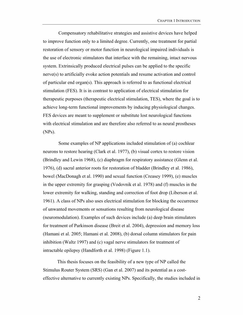
Compensatory rehabilitative strategies and assistive devices have helped
to improve function only to a limited degree. Currently, one treatment for partial
restoration of sensory or motor function in neurological impaired individuals is
the use of electronic stimulators that interface with the remaining, intact nervous
system. Extrinsically produced electrical pulses can be applied to the specific
nerve(s) to artificially evoke action potentials and resume activation and control
of particular end organ(s). This approach is referred to as functional electrical
stimulation (FES). It is in contrast to application of electrical stimulation for
therapeutic purposes (therapeutic electrical stimulation, TES), where the goal is to
achieve long-term functional improvements by inducing physiological changes.
FES devices are meant to supplement or substitute lost neurological functions
with electrical stimulation and are therefore also referred to as neural prostheses
(NPs).
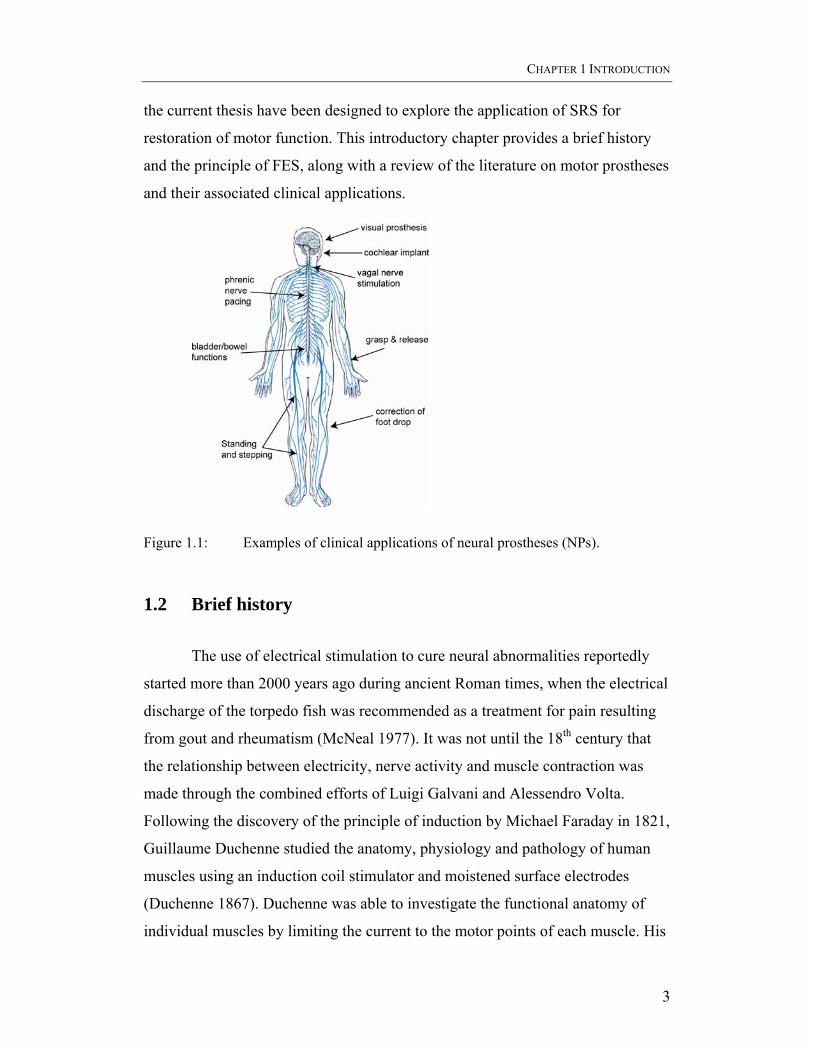
Some examples of NP applications included stimulation of (a) cochlear
neurons to restore hearing (Clark et al. 1977), (b) visual cortex to restore vision
(Brindley and Lewin 1968), (c) diaphragm for respiratory assistance (Glenn et al.
1976), (d) sacral anterior roots for restoration of bladder (Brindley et al. 1986),
bowel (MacDonagh et al. 1990) and sexual function (Creasey 1999), (e) muscles
in the upper extremity for grasping (Vodovnik et al. 1978) and (f) muscles in the
lower extremity for walking, standing and correction of foot drop (Liberson et al.
1961). A class of NPs also uses electrical stimulation for blocking the occurrence
of unwanted movements or sensations resulting from neurological disease
(neuromodulation). Examples of such devices include (a) deep brain stimulators
for treatment of Parkinson disease (Breit et al. 2004), depression and memory loss
(Hamani et al. 2005; Hamani et al. 2008), (b) dorsal column stimulators for pain
inhibition (Waltz 1997) and (c) vagal nerve stimulators for treatment of
intractable epilepsy (Handforth et al. 1998) (Figure 1.1).
This thesis focuses on the feasibility of a new type of NP called the
Stimulus Router System (SRS) (Gan et al. 2007) and its potential as a cost-
effective alternative to currently existing NPs. Specifically, the studies included in
2
CHAPTER 1 INTRODUCTION
the current thesis have been designed to explore the application of SRS for
restoration of motor function. This introductory chapter provides a brief history
and the principle of FES, along with a review of the literature on motor prostheses
and their associated clinical applications.
Figure 1.1: Examples of clinical applications of neural prostheses (NPs).
1.2 Brief history
The use of electrical stimulation to cure neural abnormalities reportedly
started more than 2000 years ago during ancient Roman times, when the electrical
discharge of the torpedo fish was recommended as a treatment for pain resulting
from gout and rheumatism (McNeal 1977). It was not until the 18th century that
the relationship between electricity, nerve activity and muscle contraction was
made through the combined efforts of Luigi Galvani and Alessendro Volta.
Following the discovery of the principle of induction by Michael Faraday in 1821,
Guillaume Duchenne studied the anatomy, physiology and pathology of human
muscles using an induction coil stimulator and moistened surface electrodes
(Duchenne 1867). Duchenne was able to investigate the functional anatomy of
individual muscles by limiting the current to the motor points of each muscle. His
3
CHAPTER 1 INTRODUCTION
work, De l'électrisation localisée et de son application à la physiologie, à la
pathologie et à la thérapeutique, published in 1867 not only contributed to the
understanding of electrophysiology and muscle movements, but also provided
much of the basic knowledge for FES. The use of electrical stimulation in
medicine remained limited until the invention of transistors in 1947. Transistors
allowed for portability of stimulator devices and increased feasibility of clinical
use (Hambrecht 1990).
1.3 Principles of functional electrical stimulation
Neurons, like most cells in the body, contain a slight excess of negative
charge (i.e. the voltage inside the cell is slightly more negative compared to that
in the extracellular space). This transmembrane potential is dependent on the
permeability and concentration gradient of ions across the membrane, which are
in turn, dependent on voltage gated ion channels (Na+, K+, Cl-, and Ca2+) and
ionic pumps at the cell membranes (Koester and Siegelbaum 2000). Sufficient
depolarization (transmembrane potential becoming less negative) of the neuronal
membrane increases the permeability of the sodium channels to allow for a
substantial influx of sodium ions that consequently initiates an action potential.
In the normal nervous system, action potentials in neurons arise from
synaptic currents in dendrites that contribute to the depolarization of the somatic
membrane. The generation of action potentials is primarily dependent on the
activation of sodium voltage-gated channels. Once initiated at the axon hillock,
the action potentials propagate along the axons to their intended target, such as
another neuron or in the case of a motor neuron, a neuromuscular junction.
Extracellular activation of a neuron is achieved by the application of a rapidly
changing electrical field in the vicinity of the nerve cell bodies or fibres which
serve to artificially depolarize the somatic or axonal membrane, thereby eliciting a
propagating action potential. An action potential evoked in this manner is
indistinguishable by the end target from one generated naturally. The electrical
4
CHAPTER 1 INTRODUCTION
generation of such artificial neural signals to control an end organ forms the basis
of NPs.
1.3.1 Properties of extracellular stimulation
Electrical activation of the neuronal membrane can be mediated by placing
electrodes inside or outside of a cell. Current flowing from the inside to the
outside of the neuronal membrane will produce depolarization of the membrane,
provided the current amplitude is large enough. With present technologies, only
extracellular electrodes are possible for implementation of FES. The role of the
extracellular electrodes therefore is to impose an electric field that produces an
outward current across the neuronal membrane to achieve excitation. At least two
electrodes are needed to produce current flow. The electrodes are typically
arranged in either bipolar or monopolar configurations. With both configurations,
the stimulating electrode, whose voltage with respect to the other (indifferent)
electrode transiently goes negative, is placed near the excitable tissue. This
electrode is generally referred to as the cathode. In the monopolar configuration,
the indifferent electrode (the anode), that serves to complete the electrical circuit
is placed some distance away from the cathode and the target excitable tissue. In
bipolar stimulation, the indifferent electrode is placed close to the cathode, thus
condensing the electric field within a smaller volume.
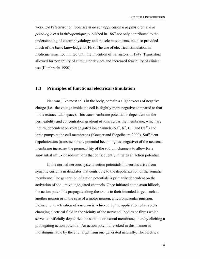
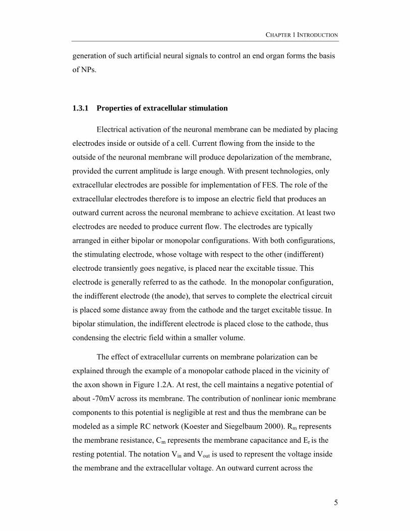
The effect of extracellular currents on membrane polarization can be
explained through the example of a monopolar cathode placed in the vicinity of
the axon shown in Figure 1.2A. At rest, the cell maintains a negative potential of
about -70mV across its membrane. The contribution of nonlinear ionic membrane
components to this potential is negligible at rest and thus the membrane can be
modeled as a simple RC network (Koester and Siegelbaum 2000). Rm represents
the membrane resistance, Cm represents the membrane capacitance and Er is the
resting potential. The notation Vin and Vout is used to represent the voltage inside
the membrane and the extracellular voltage. An outward current across the
5
CHAPTER 1 INTRODUCTION
membrane discharges Cm and causes membrane depolarization. An inward
current has the opposite effect: charges are added to the membrane capacitance
and cause hyperpolarization.
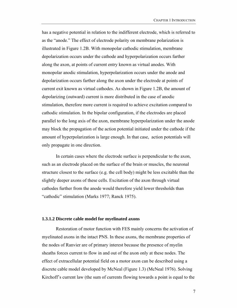
Figure 1.2: Effects of extracellular current and electrode polarity on membrane polarization. A) The effect of extracellular current on membrane polarization in the vicinity of a monopolar electrode. An outward current across the membrane discharges Cm and reduces the polarization of the membrane. An inward current adds charge to Cm and causes hyperpolarization. B) The effect of monopolar electrode polarity on membrane polarization. With cathodic stimulation, depolarization occurs directly under the electrode and hyperpolarization occurs farther along the axon, at points of current entry (virtual anodes) (Mortimer and Bhadra 2004). With anodic stimulation, hyperpolarization occurs directly under the electrode and depolarization occurs farther along the axon under the electrode at points of current exit (virtual cathodes) (Mortimer and Bhadra 2004).
1.3.1.1 Effect of electrode polarity on activation thresholds
In FES applications, activation of the nerve axons is typically achieved by
placing a cathode as close as possible to the excitable tissue to minimize the
current needed to achieve activation (i.e. to lower the threshold). As alluded to
above, by convention, the term “cathode” refers to the electrode that transiently
6
CHAPTER 1 INTRODUCTION
has a negative potential in relation to the indifferent electrode, which is referred to
as the “anode.” The effect of electrode polarity on membrane polarization is
illustrated in Figure 1.2B. With monopolar cathodic stimulation, membrane
depolarization occurs under the cathode and hyperpolarization occurs farther
along the axon, at points of current entry known as virtual anodes. With
monopolar anodic stimulation, hyperpolarization occurs under the anode and
depolarization occurs farther along the axon under the electrode at points of
current exit known as virtual cathodes. As shown in Figure 1.2B, the amount of
depolarizing (outward) current is more distributed in the case of anodic
stimulation, therefore more current is required to achieve excitation compared to
cathodic stimulation. In the bipolar configuration, if the electrodes are placed
parallel to the long axis of the axon, membrane hyperpolarization under the anode
may block the propagation of the action potential initiated under the cathode if the
amount of hyperpolarization is large enough. In that case, action potentials will
only propagate in one direction.
In certain cases where the electrode surface is perpendicular to the axon,
such as an electrode placed on the surface of the brain or muscles, the neuronal
structure closest to the surface (e.g. the cell body) might be less excitable than the
slightly deeper axons of these cells. Excitation of the axon through virtual
cathodes further from the anode would therefore yield lower thresholds than
“cathodic” stimulation (Marks 1977; Ranck 1975).
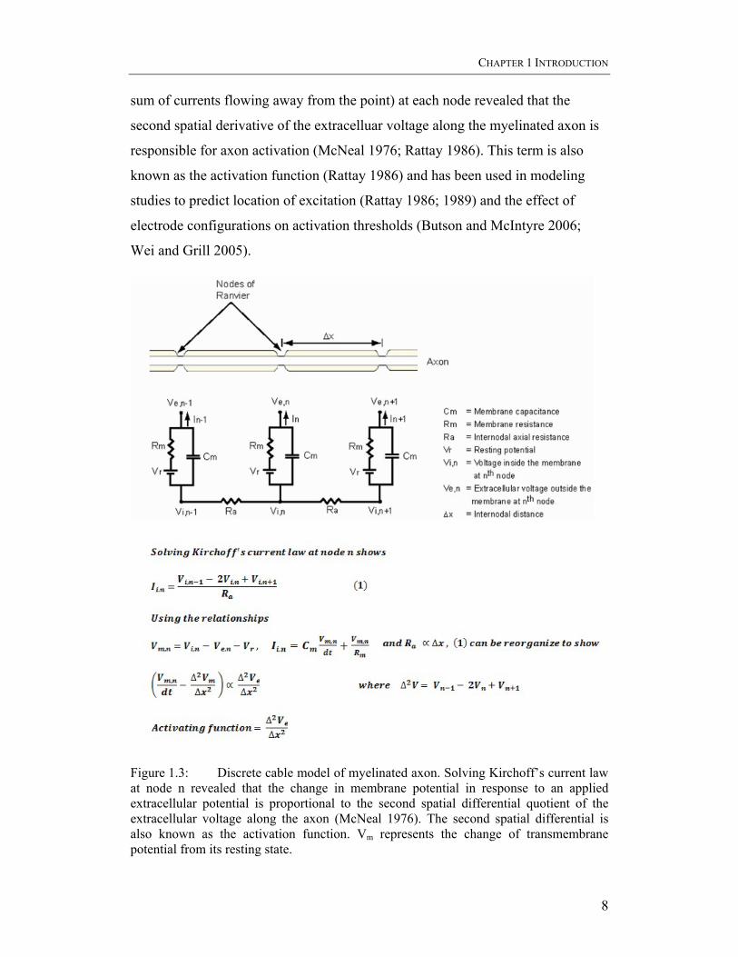
1.3.1.2 Discrete cable model for myelinated axons
Restoration of motor function with FES mainly concerns the activation of
myelinated axons in the intact PNS. In these axons, the membrane properties of
the nodes of Ranvier are of primary interest because the presence of myelin
sheaths forces current to flow in and out of the axon only at these nodes. The
effect of extracellular potential field on a motor axon can be described using a
discrete cable model developed by McNeal (Figure 1.3) (McNeal 1976). Solving
Kirchoff’s current law (the sum of currents flowing towards a point is equal to the
7
CHAPTER 1 INTRODUCTION
sum of currents flowing away from the point) at each node revealed that the
second spatial derivative of the extracelluar voltage along the myelinated axon is
responsible for axon activation (McNeal 1976; Rattay 1986). This term is also
known as the activation function (Rattay 1986) and has been used in modeling
studies to predict location of excitation (Rattay 1986; 1989) and the effect of
electrode configurations on activation thresholds (Butson and McIntyre 2006;
Wei and Grill 2005).
Figure 1.3: Discrete cable model of myelinated axon. Solving Kirchoff’s current law at node n revealed that the change in membrane potential in response to an applied extracellular potential is proportional to the second spatial differential quotient of the extracellular voltage along the axon (McNeal 1976). The second spatial differential is also known as the activation function. Vm represents the change of transmembrane potential from its resting state.
8
CHAPTER 1 INTRODUCTION
1.3.1.3 Effect of axon diameter on activation threshold
Since the distance between nodes of Ranvier is proportional to axon
diameter (~100 times axon diameter), at the vicinity of the stimulating electrode,
large diameter axons “see” larger potential differences between pairs of nodes of
Ranvier compared to small diameter axons and thus the larger axons have lower
thresholds. Using the discrete cable model, McNeal showed that in large diameter
axons (>15µm), the activation threshold is approximately inversely proportional
to the square root of axon diameter, whereas in small diameter axons (<5µm), the
threshold approaches an inverse square relationship with axon diameter (McNeal
1976). This means that there will be less selectivity among axons of different
diameters in the larger diameter range than in the small diameter range.
1.3.1.4 Effect of axon-electrode distance on activation threshold
The activation threshold is also dependent on axon-electrode distances.
The farther away the axon from the stimulating electrode, the smaller the voltage
differences along the axon and thus more current will be needed to activate the
nerve. The activation threshold was found to be proportional to electrode-axon
distance only at very small distances (< 1mm) (Ranck 1975). At distances greater
than 1mm, the relationship between activation threshold and electrode-axon
distance approaches a quadratic function (Grill 2004; Rattay 1989).
1.3.1.5 Strength-duration curve
Generation of action potentials across the axonal membrane depends on
the transient, intrinsic properties of the sodium-gated membrane channels. Hence,
electrical activation of the axon requires the application of a rapidly changing
electric potential field. This is accomplished through delivery of current- or
voltage-controlled pulses to the vicinity of the excitable tissue. When stimulating
current is being passed in constant-current pulses, the relation between the current
amplitude and pulse duration is described by the strength-duration curve (Figure
9
CHAPTER 1 INTRODUCTION
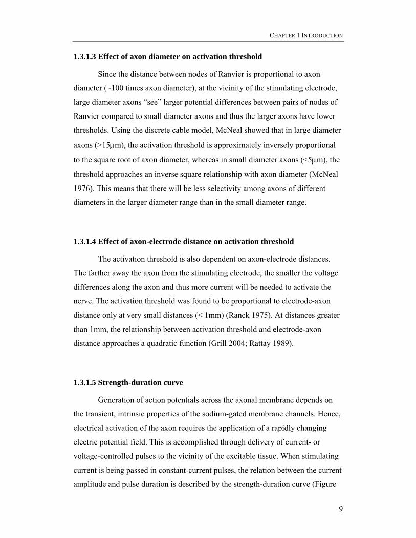
1.4). The curve shows that higher current amplitudes are needed to achieve
excitation as narrower stimulation pulses are employed. Plotting the total charge
injected (charge = current x duration) against the stimulus pulse duration reveals
that less charge is needed to achieve excitation the shorter the pulse duration.
With implanted electrodes, narrow stimulation pulses are preferred to avoid
irreversible chemical reactions at the electrode-tissue interfaces (see below).
Figure 1.4: Strength-duration and charge-duration curves. A) Strength-duration curve that describes the relationship between activation threshold and duration of stimulation pulse delivered. Rheobase is the theoretical threshold current required in an infinitely long duration pulse. Chronaxie is the stimulus pulse duration needed to achieve activation threshold at two times rheobase. B) Charge-duration curve indicates that the amount of charge needed to achieve activation increases with stimulus pulse duration. (adapted from Durand 2000).
1.3.2 Electrochemistry at electrode tissue interface
Electric charge and current are carried by electrons in an electronic circuit
(stimulator and electrodes) whereas in bodily tissues/fluids they are carried by
10
CHAPTER 1 INTRODUCTION
ions. At the electrode-tissue interface, charge injection requires a change of
carrier and this can be achieved through two mechanisms: capacitive or faradic
(Robblee and Rose 1990). The capacitive mechanism involves attraction and
repulsion of ions in the tissue fluid in response to changes in electrostatic charge
on the electrode surface. Opposite charges build up on either side of the interface
and form a capacitive “double layer”. In this case, charge carriers do not cross the
interface and charge transfer is induced through the charging and discharging of
the capacitive double-layer. The Faradaic mechanism involves electron transfer
across the interface boundary and hence necessitates chemical species to be
oxidized or reduced. These electrochemical reactions occur when the voltage
across the electrode-tissue interface reaches the free energy barrier of the
reactions in question and can be divided into reversible and irreversible reactions.
Reversible reactions involve generation of chemical species that are immobilized
to the electrode surfaces and can be ‘reversed’ by changing the polarity of the
applied potential. In FES, this often requires the use of biphasic stimulation
waveforms, in which the charge injected in the primary phase serves to elicit an
action potential while that injected in the second phase serves to discharge the
capacitive component of the interface and minimize potentially damaging
electrochemical processes that can occur within the tissue. On the other hand,
irreversible reactions occur involving the generation of chemical species that may
diffuse into the surrounding tissue and are therefore not available to carry the
opposite flow of current. Irreversible reactions can cause electrode corrosion or
tissue damage either by inducing pH changes or generation of cytotoxic radicals.
The safe limits for preventing such reactions depend on the electrode materials
and the amount of charge injected per unit of electrode surface area (charge
density). In platinum iridium and stainless steel, two metals commonly employed
for implanted NPs, the safety limits with charge-balanced biphasic stimulation
were found to be 0.75-3.0µC/mm2/phase (Robblee and Rose 1990) and
0.4µC/mm2/phase (Mortimer 1981) respectively.
11
CHAPTER 1 INTRODUCTION
1.3.3 Muscle activation
The restoration of motor function with FES operates under the
fundamental principle that electrical stimulation activates nerves rather than
muscles. The amount of current needed to activate muscle fibres directly was
shown to be more than 10 times greater than that needed to activate the nerves
that innervate them (Crago et al. 1974). At such levels, tissue damage will likely
occur either as a result of direct heating of the tissue or creation of toxic chemical
ions as a result of irreversible electrochemical reactions at the electro-tissue
interface (Robblee and Rose 1990). Hence, in FES applications, activation of the
target muscles is actually mediated through the activation of the nerve that
innervates that muscle. The lower motor neuron therefore needs to be intact from
the ventral horn of the spinal cord to the neuromuscular junction of the target
muscles. In addition, healthy neuromuscular junctions and muscle tissues are
needed to elicit optimal functional muscle contractions.
1.3.3.1 Reverse recruitment order
In voluntary contraction, the recruitment of motor units follow the “size
principle”, that is the small motor units are activated followed by the large motor
units (Henneman 1985). Since large diameter axons (which innervate large motor
units) are more readily excitable than small diameter axons (which innervate
small motor units) with electrical stimulation, in electrically induced muscle
contraction large motor units are often recruited before small motor units. The
activation of large motor units before small motor units is known as “reverse
recruitment order.” While this is generally accepted as a basic characteristic of
FES (Mortimer 1981), it should be noted that the activation threshold of an axon
is also dependent on the axon-electrode distance which influences the electrical
potential field along the axon (see section 1.3.1). Therefore, in practice, the
recruitment order of axons can be affected by the relative location between the
electrode and the nerve being stimulated (Mortimer 1981; Popovic et al. 1991;
12
CHAPTER 1 INTRODUCTION
Singh et al. 2000) as well as the morphological organization of the axonal
branches (Feiereisen et al. 1997; Grinberg et al. 2008) and therefore is not
necessarily the strict reverse of the physiological order (Gregory and Bickel
2005).
1.3.3.2 Force modulation
FES stimulation is delivered as trains of electrical current pulses
characterized by three parameters: pulse frequency, amplitude and duration. The
strength of muscle contraction can be controlled by modulation of these
parameters to achieve spatial or temporal summation of force. Increasing the
pulse duration or stimulus amplitude increases the total amount of charge being
injected into the extracellular space adjacent to the muscle nerves, thereby
producing a larger electric field, and a larger number of recruited axons. Increase
in muscle contraction strength is therefore a result of an increase in the number of
axons (motor units) activated (spatial summation).
The strength of muscle contraction can also be controlled by increasing
the stimulation frequency. Delivery of one stimulus pulse to the motor nerve
results in one muscle twitch. Repeated stimuli delivered at low frequencies result
in repeated twitches. Above 15 pulses/s, the cumulative effect of repeated stimuli
results in a smooth muscle contraction (temporal summation of muscle twitches)
(Peckham and Knutson 2005). Increase in muscle contraction can be achieved
through higher stimulation rates up to about 50 pulses/s (Solomonow 1984).
However, high-frequency stimulation can cause muscle fatigue. Hence, control of
force in FES application is typically achieved through pulse duration or amplitude
modulation.
1.3.3.3Muscle fatigue
Fatigue refers to the reduction in force observed when a muscle sustains a
contraction or a regular sequence of contractions. Electrically induced muscle
13
CHAPTER 1 INTRODUCTION
contractions result in increased fatigue compared to voluntary contractions
because many of the recruitment strategies and adaptive mechanism used to deter
fatigue in voluntary contraction are not available with electrical stimulation
(Salmon 2004). In voluntary contraction, the small motor units are recruited
before the large motor units are recruited (Henneman 1985). Small motor units
typically consist of slow twitch, oxidative (SO) muscle fibres that generate small
forces. These muscle fibres do not fatigue rapidly and recover quickly after
prolonged activation. Large motor units typically consist of fast twitch, glycolytic
muscle fibres (FG) that generate large forces. These muscle fibres fatigue easily
and recover slowly after prolonged stimulation. Thus, with voluntary contraction,
the motor units recruited most frequently are the ones that have the metabolic
capacity for sustained use. As discussed in 1.3.3.1, electrically-induced muscle
contraction does not follow this natural order of recruitment. The large motor
units can be preferentially activated with FES, causing muscle fatigue after short
activation intervals. Also, with voluntary contraction, the firing rates of the motor
units are constantly modulated so that the desired force can be maintained at the
lowest metabolic cost, whereas with FES, motor units are typically activated
synchronously at a constant rate, causing muscles to fatigue more easily.
Muscle fatigue is therefore of particular concern in FES since the inability
to maintain or produce a useful contraction can have serious consequences in
applications such as the restoration of respiratory function and walking. In
addition, long-term disuse of paralyzed muscles results in a transformation of the
muscle fibres from the SO to the FG type. Therefore, implementation of FES
systems typically requires weeks or months of muscle training. Stimulation
techniques that activate separate portions of the muscle sequentially to achieve a
smooth muscle contraction have also been employed to minimize muscle fatigue
(Peckham et al. 1970; Thoma et al. 1988).
14
CHAPTER 1 INTRODUCTION
1.4 Limitations of FES for restoration of motor function
As mentioned previously, effective application of FES requires intact
lower motor neurons and healthy neuromuscular junctions and muscle tissues.
Such limitations hinder the use of motor prostheses for activation of denervated
muscles resulting from peripheral nerve injuries, including cauda equina damage
in paraplegia or lower motor neuron diseases, such as polio and amyotrophic
lateral sclerosis (ALS). The use of FES is also limited in subjects who suffer
serious cases of spasms, spasticity or muscle contractures. In these subjects,
muscles are spontaneously active and this can be a contraindication to FES
treatment.
1.5 Motor prosthesis
1.5.1 Stimulators
The stimulators used in NPs deliver either voltage-controlled or current-
controlled electrical stimulus. Current-controlled stimulators are usually preferred
since they ensure a constant level of delivered stimulus current, regardless of
electrode-tissue impedance variability. Motor responses in relation to current-
controlled stimulation are therefore more repeatable. However, poor electrode
contact can result in high electro-tissue impedance and hence, high voltage levels
across the electro-tissue interfaces (Ohm’s Law: voltage is the product of current
and resistance) and can potentially cause tissue burns. With surface electrodes,
electrode-tissue impedances can increase as the electrodes dry or lose contact.
Therefore, current-controlled stimulators preferably have safeguards such as
impedance-sensing or limited compliance voltages to avoid causing skin burns. In
contrast, voltage-controlled stimulators ensure that desired output voltage levels
are maintained. In this case, the amount of current being delivered is dependent
on the electrode-tissue impedance. Consequently, the stimulation level, and thus
15
CHAPTER 1 INTRODUCTION
motor responses will vary depending on the goodness of electrode contact.
However, the risk of tissue burn or damage is low.
1.5.2 Electrodes
1.5.2.1 Surface electrodes
Electrodes that are placed on the surface of the body typically consist of a
flat conductor that is made of metal, carbon or carbonized rubber with an interface
of adhesive hydrogel or wettable cloth material (Stein and Prochazka 2009).
These electrodes are typically used for activation of the superficial muscles.
Selective activation of deep or small muscles is difficult with these electrodes.
Moreover, in the case of large muscles (such as biceps or triceps brachii), the
relative movement between the muscles and skin during activity can alter the
stimulation-force relationship (Stein and Prochazka 2009).
1.5.2.2 Implanted electrodes
Electrodes implanted in the body are closer to the nerve and therefore have
better stimulation selectivity compared to surface electrodes. Selectivity refers to
the ability to achieve isolated activation of the target muscle. Several types of
implanted electrodes exist including: (a) epimysial electrodes which can be
placed on the surface of the muscle (Grandjean and Mortimer 1986); (b)
intramuscular electrodes that are placed in the muscle (Caldwell and Reswick
1975; Cameron et al. 1998; Memberg et al. 1994; Peterson et al. 1994; Prochazka
and Davis 1992; Scheiner et al. 1994); (c) epineural electrodes that are placed on
the surface of the nerve trunk (Nashold et al. 1979); (d) nerve cuff electrodes that
encircle the nerve trunk (Agnew et al. 1989; Brindley 1972; McNeal and Bowman
1985; Naples et al. 1988; Tyler and Durand 2002) and (e) intrafasicular electrodes
that penetrate the nerve trunk (Yoshida and Horch 1993). In general, muscle-
based electrodes allow for activation of individual muscles but require higher
current levels to achieve activation compared to nerve-based electrodes (Popovic
16
CHAPTER 1 INTRODUCTION
2004). The motor responses elicited with muscle electrodes tend to change more
as the muscle changes its length during activity. However, since muscle
electrodes are not directly in contact with the nerves, they are less likely to cause
mechanical damage to the neural tissues. Nerve-based electrodes have lower
muscle activation thresholds. In addition, one nerve cuff electrode can be used to
activate several synergistic muscles that are innervated by the same nerve trunk.
Different stimulation techniques can also be implemented with specifically
designed, multipolar nerve cuff electrodes to achieve selective activation or
inhibition of specific fascicles in the nerve trunks (Brindley and Craggs 1980;
Fang and Mortimer 1991; Tarler and Mortimer 2004; van den Honert and
Mortimer 1981). The main concern with using nerve-based electrodes is potential
nerve damage caused by the implantation procedure or compression, tension and
torsion of the nerve trunk due to the presence the electrode.
1.5.3 Existing configurations
NP configurations can be categorized according to the location of the
stimulator and electrodes in relation to the body. Currently existing NPs are either
surface, percutaneous or implanted systems.
1.5.3.1 Surface systems
Surface systems use external stimulators to deliver stimulus currents to
pairs of surface electrodes placed on the skin which are situated over the target
nerves or the motor points of the target muscles. The motor point for a particular
target muscle is the location where the least amount of current is required to
activate that muscle. The major advantages of surface systems are that they are
non-invasive and relatively inexpensive. In addition, surgery is not required,
therefore reducing costs, risks and recovery time typically associated with
implanted systems. Surface electrodes can be easily removed if the system is
found to be unsatisfactory or is no longer beneficial (Stein and Prochazka 2009).
17
CHAPTER 1 INTRODUCTION
However, the performance of surface electrode systems can change as a result of
small shifts in electrode position, leading to the potential stimulation of nerves
and muscles other than those targeted. Isolated activation of deep lying muscles is
difficult whereas activation of the cutaneous sensory fibres may cause discomfort
or pain in sensate skin. Appropriate placement of electrodes to elicit the desired
responses becomes more difficult as the number of target muscles (stimulation
channels) increases (Triolo et al. 1996). Daily donning and doffing of the
electrodes and stimulator may be inconvenient and poses an extra burden to the
user or the caregiver. In addition, the appearance and use of the device might
attract unwanted attention or be considered aesthetically unacceptable by the user.
1.5.3.2 Percutaneous systems
Percutaneous systems make use of intramuscular electrodes that can be
implanted into the muscles via hypodermic needles (Caldwell and Reswick 1975;
Handa et al. 1989; Marsolais and Kobetic 1986; Peterson et al. 1989; Prochazka
and Davis 1992; Scheiner et al. 1994). Prior to implantation, the motor point of
the target muscle is identified through electrical stimulation with a needle probe.
A guide needle containing the intramuscular electrode is then introduced to the
motor point along with the probe. The guide needle is withdrawn when the
desired muscle contraction is obtained whereas the ‘barb’ at the end of the
electrode anchors the electrode in its optimal position (Figure 1.5). A connector is
placed at the skin surface where electrode leads exit the skin to allow electronic
interfacing with an external stimulator. A large surface electrode is typically used
as the indifferent electrode. These systems can selectively activate deep lying
muscles to produce reliable and repeatable muscle contractions (Popovic 2004).
Discomfort or pain caused by activation of the cutaneous fibres is likely avoided
since most of the electrode bypasses the skin. Also, removal of the percutaneous
electrode is relatively simple, offering a flexible method for short term testing of
implantable FES applications. However, the electrode lead exit sites at the skin
surface run the risk of infection (Knutson et al. 2002; Stein and Prochazka 2009).
18
CHAPTER 1 INTRODUCTION
Daily maintenance and inspection of the skin surface at these sites is needed. The
percutaneous skin connector can also be uncomfortable and inconvenient. In
addition, electrode leads in these systems are exposed to repeated mechanical
stress at the skin surface (Stein and Prochazka 2009). This might cause breakage
although helically coiled stainless steel wires have been shown to remain
functional for a long time (Handa et al. 1989; Knutson et al. 2002), in some cases
up to 17 years (Agarwal et al. 2003). Similar to surface systems, the aesthetics of
these systems may be considered unacceptable by patients for long term use.
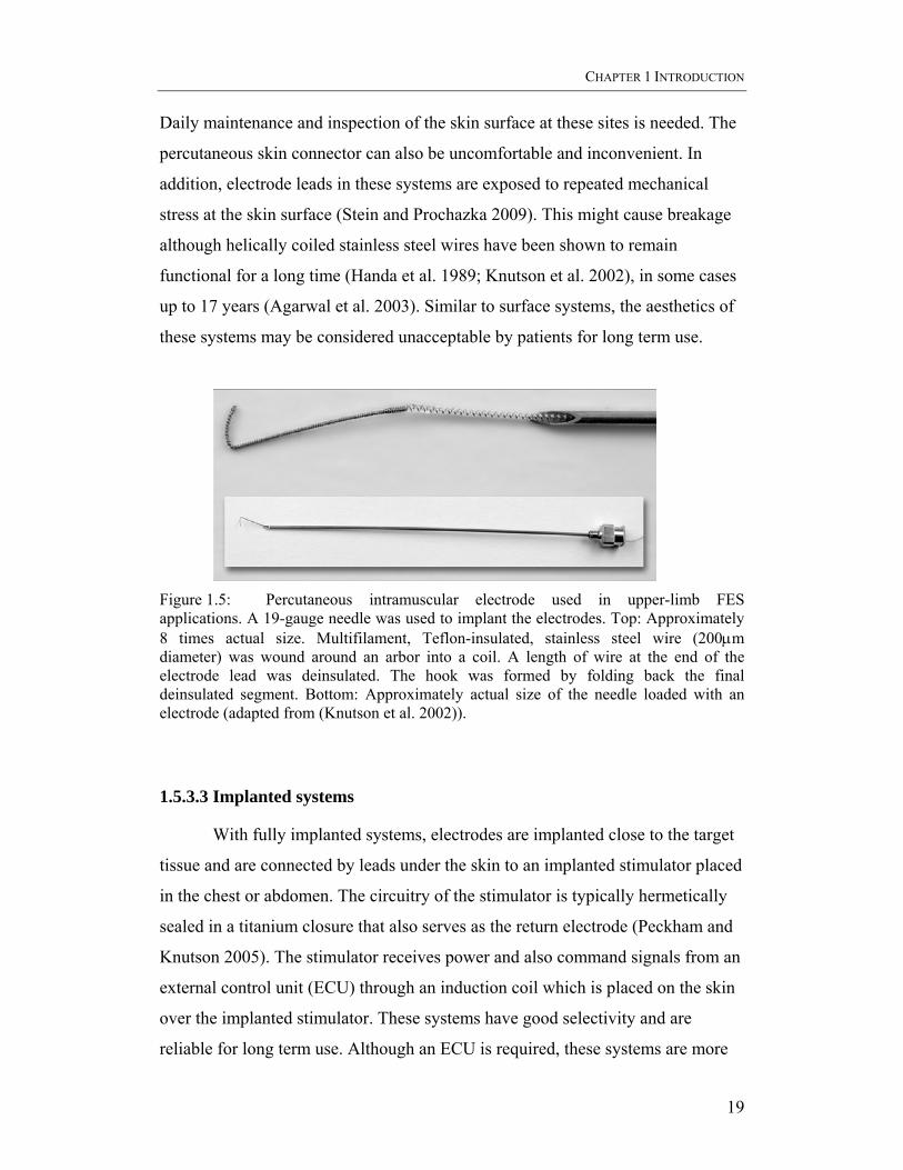
Figure 1.5: Percutaneous intramuscular electrode used in upper-limb FES applications. A 19-gauge needle was used to implant the electrodes. Top: Approximately 8 times actual size. Multifilament, Teflon-insulated, stainless steel wire (200µm diameter) was wound around an arbor into a coil. A length of wire at the end of the electrode lead was deinsulated. The hook was formed by folding back the final deinsulated segment. Bottom: Approximately actual size of the needle loaded with an electrode (adapted from (Knutson et al. 2002)).
1.5.3.3 Implanted systems
With fully implanted systems, electrodes are implanted close to the target
tissue and are connected by leads under the skin to an implanted stimulator placed
in the chest or abdomen. The circuitry of the stimulator is typically hermetically
sealed in a titanium closure that also serves as the return electrode (Peckham and
Knutson 2005). The stimulator receives power and also command signals from an
external control unit (ECU) through an induction coil which is placed on the skin
over the implanted stimulator. These systems have good selectivity and are
reliable for long term use. Although an ECU is required, these systems are more
19
CHAPTER 1 INTRODUCTION
convenient than surface systems because they do not require daily application of
electrodes. However, costs associated with the device, surgery and post-surgical
recovery are high. Depending on the number of stimulation channels, the surgery
can be rather invasive and therefore increase the trauma, risk of infection, post
operative pain and hospitalization and recovery time. Furthermore, the leads,
electrodes and stimulator are inaccessible for maintenance and servicing in case
of breakage, failure or infection. Additional surgery might be required to replace
these components for the system to be functional.
1.6 Clinical applications
The use of NPs can be observed in a variety of applications, some of
which have reached the stage of clinical testing and commercialization. In
general, the commercialization and acceptance of NPs have been more successful
in applications that require no or minimal sensory feedback, such as the case with
rhythmic stimulation of the diaphragm for restoration of respiratory function. Due
to the complexity of multi-joint movements and the lack of intuitive control
mechanisms, the functional outcome of most NPs for restoration of upper and
lower limb functions has remained limited. The lack of functional gain and the
time, cognitive and physical demand required for these systems often result in
NPs being used only as therapeutic/exercise devices as opposed to the original
intention to assist in activities of daily living (ADLs). This section describes some
experimental and commercial NPs for restoration of upper extremity, lower
extremity, bladder and respiratory function.
1.6.1 Upper extremity
Almost all NPs for upper extremity function have focused on restoration
of grasp and release in individuals with C5-6 level SCI and hemiplegia.
Restoration of arm and hand function is considered the highest priority in
20
CHAPTER 1 INTRODUCTION
tetraplegic subjects (Anderson 2004). SCI subjects with a C5-6 level injury
typically retain voluntary control of shoulder and elbow flexors with little or no
voluntary control of the wrist and hand muscles. As a result, these subjects can
bring their forearms close to the mouth or head, a motion essential for many self-
care skills, but do not have the control or strength to manipulate objects with their
hands. These individuals can greatly benefit from restoration of hand function to
achieve more independence in ADLs. Two types of grasp that are of particular
interest are the palmar grasp and lateral pinch. The palmar grasp is used for
securing bigger and heavier objects such as cans and bottles while lateral pinch is
used for grasping smaller, thinner objects such as papers and keys (Popovic et al.
2002). In hemiplegic subjects, the action of the impaired hand is often dominated
by excess activities in the finger and wrist flexors. These individuals therefore
retained the ability to grasp, but cannot easily release an object. Activation of the
wrist and finger extensors by NPs can restore of hand opening.
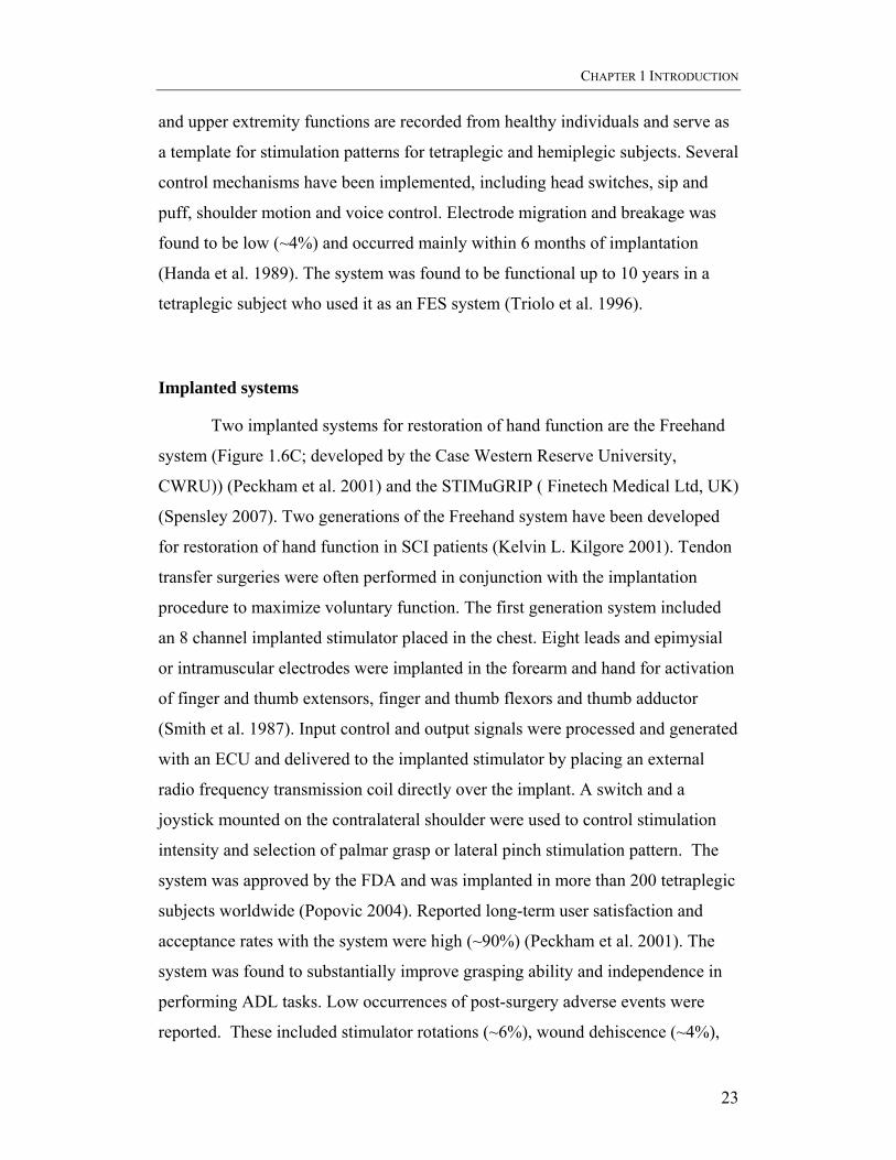
Surface systems
Surface NP for restoration of hand function included the NESS H200
(formerly Handmaster, Bioness Inc., Valencia, Ca) and the Bionic Glove (Figure
1.6A & B) Both systems activate the finger and thumb flexors and finger
extensors for restoration of palmar grasp, lateral pinch and hand opening. In both
systems, reported functional gains included increases in grip strength,
improvements in hand function and reduced time or difficulty in performing
selected ADLs. The NESS H200 is a commercially available system that consists
of an orthotic splint for wrist support and 5 built-in surface electrodes. Triggering
of preprogrammed stimulation patterns along with control of stimulation
intensities are accomplished through push buttons and a potentiometer located on
a separate, portable external stimulator. One of the disadvantages of the device is
the interference of the rigid splint with voluntary wrist extension. Also, control
and donning and doffing of the device can be difficult depending on the
functional level of the contralateral hand (Snoek et al. 2000). In individuals
21
CHAPTER 1 INTRODUCTION
without voluntary wrist extension, high satisfaction rates have been reported
(>90%) (Alon and McBride 2003; Alon et al. 2002).
The Bionic Glove is a flexible garment used for augmentation of tenodesis
grasp and release in C6/7 SCI and hemiplegic individuals who have voluntary
wrist control (Prochazka et al. 1997). The tendons of the long finger flexors and
extensors slide past the wrist joint. Voluntary extension or flexion of the wrist
causes shortening of the finger flexors or extensors, resulting in a relatively weak
passive grasp or extension known as tenodesis. Wettable surface electrodes are
located inside the garment over the motor points of finger flexors, thumb flexors
and finger extensors. Another surface electrode is placed proximal to the wrist as
the return electrode. A 3-channel stimulator is located on the forearm portion of
the glove and stimulation of the muscles is triggered based on wrist positions
detected using a sensor place in the garment. Acceptance rate for long term use
was found to be about 50-60% (Popovic et al. 1999; Prochazka et al. 1997). The
main reason for discontinued use was the lack of functional gain. Reported
difficulties with the device included donning and doffing, positioning of the
surface electrodes, selective activation and discomfort due to stimulation. A new
version of the Bionic Glove, called the Hand-E-Stim, has recently been developed
and was tested as part of an in-home tele-rehabilitation study in tetraplegic
subjects (Kowalczewski et al. In submission; Kowalczewski and Prochazka
2009). The Hand-E-Stim is triggered by a wireless earpiece that detects small
tooth-clicks produced by the user (Prochazka 2005).
Percutaneous systems
The FESMate is the only percutaneous system developed for long term
use in tetraplegic and hemiplegic subjects (Handa et al. 1989). The system is only
available in Japan. It consists of a portable 30-channel stimulator and a system
controller. Up to 30 intramuscular electrodes can be implanted percutaneously in
the hand, forearm, elbow and shoulder muscles for restoration of upper extremity
functions customized to individual needs. EMG activities of several hand grasps
22
CHAPTER 1 INTRODUCTION
and upper extremity functions are recorded from healthy individuals and serve as
a template for stimulation patterns for tetraplegic and hemiplegic subjects. Several
control mechanisms have been implemented, including head switches, sip and
puff, shoulder motion and voice control. Electrode migration and breakage was
found to be low (~4%) and occurred mainly within 6 months of implantation
(Handa et al. 1989). The system was found to be functional up to 10 years in a
tetraplegic subject who used it as an FES system (Triolo et al. 1996).
Implanted systems
Two implanted systems for restoration of hand function are the Freehand
system (Figure 1.6C; developed by the Case Western Reserve University,
CWRU)) (Peckham et al. 2001) and the STIMuGRIP ( Finetech Medical Ltd, UK)
(Spensley 2007). Two generations of the Freehand system have been developed
for restoration of hand function in SCI patients (Kelvin L. Kilgore 2001). Tendon
transfer surgeries were often performed in conjunction with the implantation
procedure to maximize voluntary function. The first generation system included
an 8 channel implanted stimulator placed in the chest. Eight leads and epimysial
or intramuscular electrodes were implanted in the forearm and hand for activation
of finger and thumb extensors, finger and thumb flexors and thumb adductor
(Smith et al. 1987). Input control and output signals were processed and generated
with an ECU and delivered to the implanted stimulator by placing an external
radio frequency transmission coil directly over the implant. A switch and a
joystick mounted on the contralateral shoulder were used to control stimulation
intensity and selection of palmar grasp or lateral pinch stimulation pattern. The
system was approved by the FDA and was implanted in more than 200 tetraplegic
subjects worldwide (Popovic 2004). Reported long-term user satisfaction and
acceptance rates with the system were high (~90%) (Peckham et al. 2001). The
system was found to substantially improve grasping ability and independence in
performing ADL tasks. Low occurrences of post-surgery adverse events were
reported. These included stimulator rotations (~6%), wound dehiscence (~4%),
23
CHAPTER 1 INTRODUCTION
electrode failures (~1%) and electrode infections (~1%). The main disadvantage
of this system was the cost associated with the device, the long and invasive
surgical procedure, long recovery and implementation time (~ 3 months) and the
need for repeated surgeries in case of implant rotations, failures or infections
(Peckham et al. 2001). Also, the control mechanism prevented the system from
being implanted bilaterally. Despite satisfactory results, the manufacturer of the
original Freehand system withdrew it from the market for business reasons
(Peckham and Knutson 2005).
In a second-generation Freehand system, the implanted stimulator is
capable of bidirectional telemetry which allows the use of implanted control
sensors on the ipsilateral arm (Kilgore et al. 2001). User control of the system can
be achieved using signals derived from an implantable joint angle transducer
placed on the ipsilateral wrist or electromyography (EMG) signals from ipsilateral
muscles that remain under voluntary control. Implementation of the EMG control
strategy was shown to be successful in unilateral and bilateral implanted systems.
A 2-year follow-up study in 3 C5/6 SCI subjects demonstrated high user
satisfaction (Kilgore et al. 2008), with improvement in hand function and daily
independence similar to those reported for the previous version. No system
failures were reported by users, however, 2 out of the 6 EMG electrodes required
surgical revision due to suboptimal positioning of the recording electrodes.
The STIMuGRIP is a newly developed 2-channel implanted system for
restoration of hand opening and wrist extension following stroke (Spensley 2007;
Taylor et al. 2007). The system uses 2 epimysial electrodes that are implanted on
the finger extensors and wrist extensors. A 2-channel implanted stimulator is
placed subcutaneously within the affected forearm. Control signals and power are
delivered from an ECU to the implanted stimulator through inductive coupling.
The ECU is worn on the affected limb using a strap, over the site of the implanted
stimulator. An accelerometer is incorporated in the ECU to allow detection of
deliberate arm movement by the patient. These movements are then used to
trigger sequences of stimulation that activate the finger flexors and extensors for
24
CHAPTER 1 INTRODUCTION
hand closing and opening. The system has been implanted in two hemiplegic
patients. Preliminary results indicated that individual control of the wrist and
finger extension can be achieved with the system (Taylor et al. 2007).
Figure 1.6: Examples of available upper extremity NPs. A) The NESS H200, B) The bionic glove, C) The Freehand system
1.6.2 Lower extremity
NPs for lower extremity have mainly focused on correction of foot drop,
restoration of standing, and restoration of walking in people with either SCI or
those who have had a stroke.
1.6.2.1 Foot drop
Foot drop refers to the inability to raise the front part of the foot due to
weakness or paralysis of the dorsiflexors. As a result, individuals with foot drop
25
CHAPTER 1 INTRODUCTION
drag their toes along the ground or bend their knees to lift their foot higher than
usual to clear their foot off the ground during walking. These compensations can
result in falls or ineffective gait patterns. Foot drop can be corrected by
stimulating the common peroneal nerve to cause foot dorsiflexion at an
appropriate time point during the gait cycle (Liberson et al. 1961). However, since
the common peroneal nerve also innervates the muscles that evert the ankle, an
imbalance dorsiflexion with excessive eversion can sometimes occur. Numerous
systems have been developed for correction of foot drop and have achieved great
acceptance. Most users are people who have had a stroke but other users include
people with multiple sclerosis, or SCI when the main locomotor problem is foot
drop.
Surface systems
Numerous surface systems have been developed, including the Odstock
Footdrop Stimulator (ODFS; Odstock Medical Ltd., Salisbury, U.K.) (Burridge et
al. 1997), the WalkAide (Innovative Neurotronics, Bethesda MD) (Dai et al.
1996) and the NESS L300 (Bioness Inc., Valencia, CA) (Hausdorff and Ring
2008); all of which have received FDA approval and are commercially available.
All three systems consist of a single channel stimulator that is either worn on the
waist (ODFS) or on a cuff placed below the knee (WalkAide and NESS L300). A
pair of surface electrodes is placed on the lateral aspect of the affected leg, just
below the knee for activation of the common peroneal nerve. A pressure sensor or
foot switch is placed in the sole of the shoe for detection of heel strike.
Stimulation is triggered when the heel leaves the ground and terminated when the
heel returns to the ground. The WalkAide uses a built-in tilt sensor to detect step
intention. Stimulation is triggered when the leg is tilted back at the end of the
stance phase and terminated when the leg is tilted forward after the foot strikes the
ground. Clinical studies on these systems have indicated improvement in walking
speed and decreased effort in walking when these devices are used (Laufer et al.
2009; Stein et al. 2006; Taylor et al. 1999). The acceptance rate of these devices
has been high (ODFS: 70-75% (Lyons et al. 2002); WalkAide and NESS L300:
26
CHAPTER 1 INTRODUCTION
~90% (Hausdorff and Ring 2008; Stein et al. 2006)). Reported difficulties with
these systems include donning and doffing, positioning of the electrodes, skin
irritations due to surface electrodes and unpleasant sensations due to stimulation
(Lyons et al. 2002; Stein et al. 2006).
Implanted systems
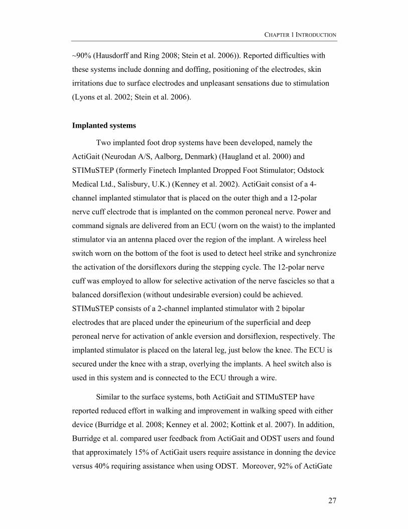
Two implanted foot drop systems have been developed, namely the
ActiGait (Neurodan A/S, Aalborg, Denmark) (Haugland et al. 2000) and
STIMuSTEP (formerly Finetech Implanted Dropped Foot Stimulator; Odstock
Medical Ltd., Salisbury, U.K.) (Kenney et al. 2002). ActiGait consist of a 4-
channel implanted stimulator that is placed on the outer thigh and a 12-polar
nerve cuff electrode that is implanted on the common peroneal nerve. Power and
command signals are delivered from an ECU (worn on the waist) to the implanted
stimulator via an antenna placed over the region of the implant. A wireless heel
switch worn on the bottom of the foot is used to detect heel strike and synchronize
the activation of the dorsiflexors during the stepping cycle. The 12-polar nerve
cuff was employed to allow for selective activation of the nerve fascicles so that a
balanced dorsiflexion (without undesirable eversion) could be achieved.
STIMuSTEP consists of a 2-channel implanted stimulator with 2 bipolar
electrodes that are placed under the epineurium of the superficial and deep
peroneal nerve for activation of ankle eversion and dorsiflexion, respectively. The
implanted stimulator is placed on the lateral leg, just below the knee. The ECU is
secured under the knee with a strap, overlying the implants. A heel switch also is
used in this system and is connected to the ECU through a wire.
Similar to the surface systems, both ActiGait and STIMuSTEP have
reported reduced effort in walking and improvement in walking speed with either
device (Burridge et al. 2008; Kenney et al. 2002; Kottink et al. 2007). In addition,
Burridge et al. compared user feedback from ActiGait and ODST users and found
that approximately 15% of ActiGait users require assistance in donning the device
versus 40% requiring assistance when using ODST. Moreover, 92% of ActiGate
27
CHAPTER 1 INTRODUCTION
users indicated that they use the device daily. In contrast, approximately half
(53%) of those with ODST devices use them daily (Burridge et al. 2008).
Recently, the BION has been implemented with the WalkAide system
(BIONic WalkAide) in one subject who suffered incomplete C6/7 SCI (Weber et
al. 2005). Similar to the surface WalkAide system, a tilt sensor is used and the
external coil and ECU for the BIONs is placed in a neoprene cuff worn below the
knee. A total of four BIONs were implanted in the subject. One BION failed
because of an electronic component weakness, whereas the other three were used
for the activation of the tibialis anterior, deep peroneal nerve and peroneal longus
respectively. The improvement in walking speed and reduced physiological effort
with BIONic WalkAide was found to be comparable with the surface WalkAide
system in the same subject. However, a more balanced ankle flexion was achieved
with BIONic WalkAide due to the ability to selectively activate the deep peroneal
nerve that only innervates the dorsiflexors.
(A) (B)
Figure 1.7: Examples of commercially available foot drop stimulators. A) WalkAide, a surface NP and B) ActiGait, an implanted NP.
28
CHAPTER 1 INTRODUCTION
1.6.2.2 Walking and standing
The ultimate goal of lower extremity NPs is to restore standing and
walking in paraplegic subjects. However, due to the complex biomechanics, high
energy demand and the issue of muscle fatigue, NPs for standing and walking
have only achieved limited functional outcomes and are typically used in
conjunction with a walker or other orthosis. Currently, only one implanted system
has been approved by the FDA for the restoration of walking.
Surface system
Parastep (Sigmedic Inc., Fairborn, OH) is an FDA approved surface NP
developed for restoration of walking in paraplegics subjects with the assistance of
a walker (Graupe and Kohn 1998). The system uses 4-6 channels of bilateral
surface stimulation for activation of a) the quadriceps for knee extension, b) the
peroneal nerves to elicit a withdrawal reflex of the hip, knee and ankle that can
substitute for the swing phase during gait, and if necessary, c) the glutei for lower
back stability and hip extension. The ECU and a microprocessing unit are worn
on the waist while the control switches are built in to the handles of the walker,
allowing the user to stand and walk with reciprocal gait for limited distance. A
study involving 400 paraplegic subjects, demonstrated that, after training, all 400
were able to achieve 20-30 feet of ambulation using this system. About a dozen
were reported to exceed half a mile without sitting down. Most subjects were able
to independently don (~10 minutes) and doff (~3 minutes) the surface electrodes.
Because only limited ambulation can be achieved, the system cannot replace the
wheelchair. However, other benefits included: (a) user independence; (b)
training of paralyzed muscles to obtain additional medical benefits (e.g., increased
blood flow to the lower extremities, reduced spasticity, increased muscle mass);
and (c) reduced heart rate at sub-peak work intensities.
29
CHAPTER 1 INTRODUCTION
Implanted systems
Numerous implanted systems have been developed for restoration of
walking. The Praxis-24 is a 22 channel system that uses intramuscular electrodes
for activation of the quadriceps, hamstrings, ankle and gluteal muscles (Johnston
et al. 2005). Control of the system is achieved through gyroscopes and
accelerometers to detect limb positions while overall user control is achieved
through a touch-sensitive LCD panel on the control unit. So far, the system has
only been implanted in a few paraplegic subjects. In a study with 3 paraplegic
subjects, walking distances up to 6m using a swing through gait was reported
(Johnston et al. 2005). Similar implanted systems also have been developed based
on the stimulator module developed in the Freehand system. A single case study
using a 16-channel system for restoration of walking has been reported in a T10
paraplegic subject (Kobetic et al. 1999). The system consists of two 8-channel
implanted stimulators placed in the lower abdomen and 14 epymisial and 2
intramuscular electrodes implanted for bilateral activation of the hip extensors,
knee flexor and extensors, ankle plantarflexors and dorsiflexors. More recently an
8-channel system has been implanted in a subject with incomplete C6/7 SCI who
was able to stand but could not walk (Hardin et al. 2007). Eight intramuscular
electrodes were implanted for bilateral activation of only the hip flexors and
abductors, knee extensors and ankle dorsiflexors. The stimulation pattern was
preprogrammed and customized to the individual and triggered using a finger or
hand switch. In both cases the systems were implemented successfully and
maximal walking distances of 25m and 300m were reported in each case (Hardin
et al. 2007; Kobetic et al. 1999). Lastly, a 12-channel implanted system that
stimulates the lumbosacral anterior roots (L2-S2) for restoration of walking
(lumbosacral anterior roots stimulation implant, LARSI) (Rushton et al. 1997) has
been attempted but did not provide adequate selectivity (Donaldson Nde et al.
2003).
An 8 channel system also has been developed by the CWRU and Veteran
Affairs (CWRU/VA) for restoration of standing and also to enable a transfer
30
CHAPTER 1 INTRODUCTION
move from a seated position to another surface (Davis et al. 2001). In this case,
the implanted stimulator is placed in the anterior lower abdomen and 8 epimysial
or intramuscular electrodes are surgically implanted for activation of the trunk,
hip and knee extensors. An ECU worn around the waist delivers power and
command signal to the implanted stimulator through an external coil taped to the
skin overlying the implanted stimulator. Triggering of the stimulation can be
controlled through push button on the ECU or a command ring worn around the
index finger and operated by the thumb. Balance and assistance is provided by
the upper limbs and an assistant or support device, such as a walker. In a study
with 13 C6-T9 SCI subjects, all but one were able to maintain more than 85% of
their body weight and could stand for 3-40 minutes (Davis et al. 2001). One
subject stopped using the system due to infection. A user survey conducted at 1
year post implant, indicated that 8 of the subjects used it regularly for standing
and exercise, one used it only for exercise and 2 subjects stopped using the system
due to lack of time and injury unrelated to the usage of the system. Although 7
falls were reported while using the system, none of them caused injury. Ten
subjects were moderately to highly satisfied with the system. Similar to ParaStep,
medical benefits associated with the usage of the system have been reported
including: reduced frequency of spasms, pressure sores and urinary tract
infection.
1.6.3 Bladder
Normal voiding of the bladder and continence require coordinated action
of the bladder detrusor muscle and the external urethral sphincter (EUS).
Coordination is controlled by the neuronal circuits in the brain and the sacral
spinal roots. Injury to the spinal cord at levels above the sacral spinal nerves
results in loss of such coordination. Subjects with injuries at the suprasacral level
often suffer simultaneous contraction of the bladder detrusor muscle and the EUS
(destrusor-sphincter dyssynergia) or involuntary contractions of the bladder
detrusor during the filling phase (detrusor hyperreflexia or neurogenic detrusor
31
CHAPTER 1 INTRODUCTION
overactivity). These conditions lead to incontinence, inefficient voiding with high
residual volume and elevated bladder pressure, ultimately resulting in renal
deterioration. One technique for restoration of voiding and continence in
individuals who suffer suprasacral SCI is the stimulation of sacral spinal roots,
which contain both the small-diameter preganglionic parasympathetic axons that
innervate the bladder detrusor muscle via the pelvic nerve and the large diameter
somatic motor axons that innervate the EUS.
Implanted system
The Finetech-Brindley system (formerly sacral anterior root stimulation
implant, SARSI, or Vocare System in North America; Finetech Medical Ltd.,
Hertfordshire, U.K.) is the first commercially available NP for restoration of
bladder control. The system was proposed by Brindley et al. (Brindley 1994;
Brindley et al. 1986) and consists of a 2-4 channel passive receiver implanted in
the abdomen area and tripolar “book” electrodes implanted on the sacral roots
(S2-4) through a laminectomy. An external transmitter held against the skin over
the implant delivers command signal and power from a handheld ECU to the
implanted stimulator using telemetry. Stimulation is triggered through a switch on
the ECU and allows bladder voiding on demand. Since the large diameter somatic
motor axons that innervate the EUS have lower thresholds, excitation of the small
diameter parasympathetic preganglionic fibres to elicit bladder contraction is
inevitably accompanied by the activation of the EUS. The system partly solves
this problem by taking advantage of the slower relaxation time of the detrusor
muscle compared to EUS muscle. Voiding is achieved in bursts through
intermittent stimulation of the sacral roots. This system has been implanted in
more than 2500 people worldwide, in some cases for over 20 years (Gaunt and
Prochazka 2006). Eighty-five to 97% of the subjects reported using the system
regularly for voiding and 68-91% have reported complete continence (Vastenholt
et al. 2003). The main disadvantage of the system is that sacral deafferentation is
often needed to achieve a better outcome, which results in loss of genital
32
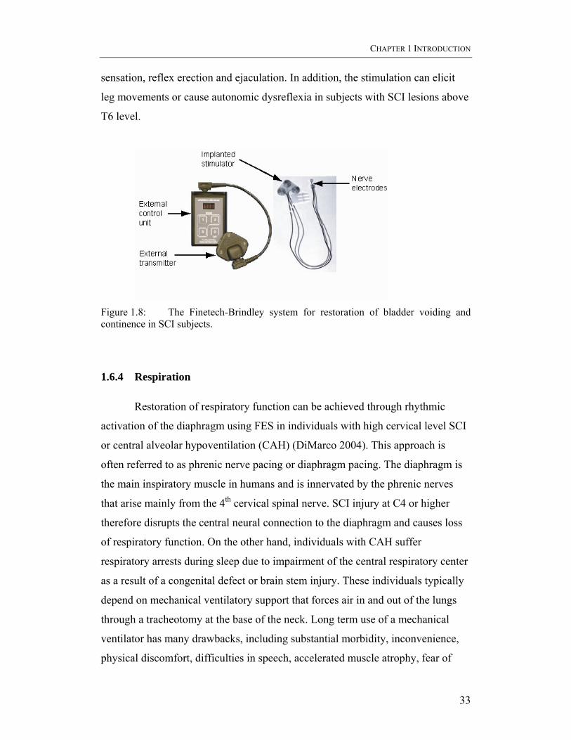
CHAPTER 1 INTRODUCTION
sensation, reflex erection and ejaculation. In addition, the stimulation can elicit
leg movements or cause autonomic dysreflexia in subjects with SCI lesions above
T6 level.
Figure 1.8: The Finetech-Brindley system for restoration of bladder voiding and continence in SCI subjects.
1.6.4 Respiration
Restoration of respiratory function can be achieved through rhythmic
activation of the diaphragm using FES in individuals with high cervical level SCI
or central alveolar hypoventilation (CAH) (DiMarco 2004). This approach is
often referred to as phrenic nerve pacing or diaphragm pacing. The diaphragm is
the main inspiratory muscle in humans and is innervated by the phrenic nerves
that arise mainly from the 4th cervical spinal nerve. SCI injury at C4 or higher
therefore disrupts the central neural connection to the diaphragm and causes loss
of respiratory function. On the other hand, individuals with CAH suffer
respiratory arrests during sleep due to impairment of the central respiratory center
as a result of a congenital defect or brain stem injury. These individuals typically
depend on mechanical ventilatory support that forces air in and out of the lungs
through a tracheotomy at the base of the neck. Long term use of a mechanical
ventilator has many drawbacks, including substantial morbidity, inconvenience,
physical discomfort, difficulties in speech, accelerated muscle atrophy, fear of
33
CHAPTER 1 INTRODUCTION
disconnection and impaired sense of smell (Levine et al. 2008; Lin and Hsiao
2008).
Implanted system
Currently 3 implanted FES systems are available for diaphragm pacing,
namely the Avery System (Avery Biomedical Devices Inc., NY), AtroStim
(Atrotech Ltd., Tampere, Finland) and MedImplant (Medimplant Inc., Vienna,
Austria). The Avery system (Figure 1.9) and AtroStim are commercially available
worldwide and use nerve cuff electrodes that are implanted on the bilateral
phrenic nerves in the cervical or thoracic region. Each nerve cuff electrode is
connected to an implanted stimulator placed in the chest. Control signals and
power are delivered to the implanted stimulators through external control units
placed over the implanted region on the chest. Monopolar or bipolar nerve cuff
electrodes can be used with the Avery system. The Atrostim utilizes a quadripolar
electrode configuration with four evenly-spaced electrode contacts placed around
the phrenic nerve. A sequential stimulation paradigm is used to reduce muscle
fatigue where each of the four contacts in turn serves as a cathode, and another
contact on the other side serve as an anode. In this way, for each inspiration the
muscle units are only activated one fourth of the time compared to conventional
monopolar stimulation. The third system, MedImplant, is only available in Europe
and requires only one implanted 8-channel stimulator for bilateral phrenic nerve
stimulation. Four epineural electrodes are sutured to each nerve and a “carousal”
stimulation technique is used to reduce fatigue. With this technique, each
inspiration is elicited through only one out of the four electrode contacts on each
nerve. Consecutive inspirations are therefore achieved through sequential
stimulation of the nerve compartments at the vicinity of each electrode contact.
The main disadvantage of these systems is a thoracotomy on the anterior
chest is often needed to allow exposure of the phrenic nerve, causing substantial
trauma and increases in surgical and recovery time. Whereas early studies with
phrenic nerve pacing reported a high incidence of failure due to technical
malfunction or patient selection error, recent follow up studies of the Avery
34
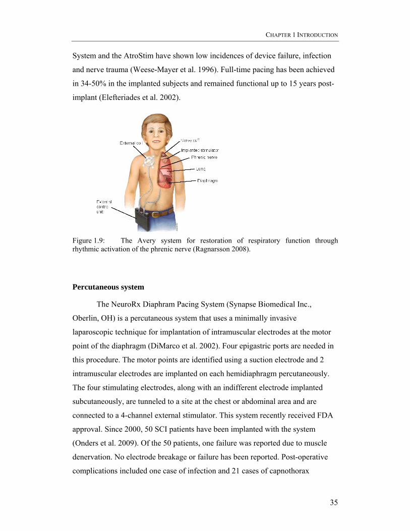
CHAPTER 1 INTRODUCTION
System and the AtroStim have shown low incidences of device failure, infection
and nerve trauma (Weese-Mayer et al. 1996). Full-time pacing has been achieved
in 34-50% in the implanted subjects and remained functional up to 15 years post-
implant (Elefteriades et al. 2002).
Figure 1.9: The Avery system for restoration of respiratory function through rhythmic activation of the phrenic nerve (Ragnarsson 2008).
Percutaneous system
The NeuroRx Diaphram Pacing System (Synapse Biomedical Inc.,
Oberlin, OH) is a percutaneous system that uses a minimally invasive
laparoscopic technique for implantation of intramuscular electrodes at the motor
point of the diaphragm (DiMarco et al. 2002). Four epigastric ports are needed in
this procedure. The motor points are identified using a suction electrode and 2
intramuscular electrodes are implanted on each hemidiaphragm percutaneously.
The four stimulating electrodes, along with an indifferent electrode implanted
subcutaneously, are tunneled to a site at the chest or abdominal area and are
connected to a 4-channel external stimulator. This system recently received FDA
approval. Since 2000, 50 SCI patients have been implanted with the system
(Onders et al. 2009). Of the 50 patients, one failure was reported due to muscle
denervation. No electrode breakage or failure has been reported. Post-operative
complications included one case of infection and 21 cases of capnothorax
35
CHAPTER 1 INTRODUCTION
associated with the laparoscopic procedure. A total of 96% of the patients used
the system for more than 4 hours continuously and 50% of the patients used the
system for over 24 hours continuously.
1.7 Emerging technologies
1.7.1 BIONs
The BION (BIOnic Neuron; Advanced Bionics, Valencia, CA) system is
an alternate approach to existing implanted NPs. It is a minimally invasive,
multichannel, wireless NP that was designed to have broad applicability (Loeb et
al. 2001). The main component of the system is the BION (Cameron et al. 1998;
Loeb et al. 1991) (Figure 1.10), which is a self-contained, single channel
microstimulator that is encapsulated in a ceramic or glass case and can be injected
into the vicinity of the target nerve with a hypodermic needle. The system does
not have electrical leads so the skin can essentially seal over the puncture wound
leaving the microstimulator completely implanted. Up to 256 BIONs (channels)
can be controlled and powered through telemetry from an external coil worn over
the implant area. The system is unique because it allows for a multichannel
configuration to be implanted without the surgical trauma and costs generally
associated with implant procedures.
Four generations of BIONs have been proposed so far (Table 1.1) (Loeb et
al. 2006). Reported clinical studies of the BION have primarily involved the first
and third generations of the BION (BION1 and BION3) for TES applications (e.g.
prevention of shoulder subluxation (Loeb et al. 2006) and retraining hand function
in stroke patients (Davis et al. 2008; Turk et al. 2008)) and neuromodulation [e.g.
treatment for urinary urge incontinence (Bosch 2005; Groen et al. 2005) and
headache (Burns et al. 2009); respectively]. The system has been proven safe and
reliable. For FES application, the feasibility of the BION1 for correction of foot
drop was shown in one stroke subject (Weber et al. 2005). However, in this
36
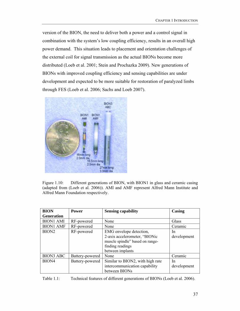
CHAPTER 1 INTRODUCTION
version of the BION, the need to deliver both a power and a control signal in
combination with the system’s low coupling efficiency, results in an overall high
power demand. This situation leads to placement and orientation challenges of
the external coil for signal transmission as the actual BIONs become more
distributed (Loeb et al. 2001; Stein and Prochazka 2009). New generations of
BIONs with improved coupling efficiency and sensing capabilities are under
development and expected to be more suitable for restoration of paralyzed limbs
through FES (Loeb et al. 2006; Sachs and Loeb 2007).
Figure 1.10: Different generations of BION, with BION1 in glass and ceramic casing (adapted from (Loeb et al. 2006)). AMI and AMF represent Alfred Mann Institute and Alfred Mann Foundation respectively.
BION Generation
Power Sensing capability Casing
BION1 AMI RF-powered None Glass BION1 AMF RF-powered None Ceramic BION2 RF-powered EMG envelope detection,
2-axis accelerometer, “BIONic muscle spindle” based on range-finding readings between implants
In development
BION3 ABC Battery-powered None Ceramic BION4 Battery-powered Similar to BION2, with high rate
intercommunication capability between BIONs
In development
Table 1.1: Technical features of different generations of BIONs (Loeb et al. 2006).
37
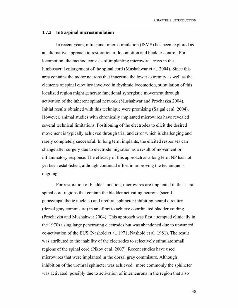
CHAPTER 1 INTRODUCTION
1.7.2 Intraspinal microstimulation
In recent years, intraspinal microstimulation (ISMS) has been explored as
an alternative approach to restoration of locomotion and bladder control. For
locomotion, the method consists of implanting microwire arrays in the
lumbosacral enlargement of the spinal cord (Mushahwar et al. 2004). Since this
area contains the motor neurons that innervate the lower extremity as well as the
elements of spinal circuitry involved in rhythmic locomotion, stimulation of this
localized region might generate functional synergistic movement through
activation of the inherent spinal network (Mushahwar and Prochazka 2004).
Initial results obtained with this technique were promising (Saigal et al. 2004).
However, animal studies with chronically implanted microwires have revealed
several technical limitations. Positioning of the electrodes to elicit the desired
movement is typically achieved through trial and error which is challenging and
rarely completely successful. In long term implants, the elicited responses can
change after surgery due to electrode migration as a result of movement or
inflammatory response. The efficacy of this approach as a long term NP has not
yet been established, although continual effort in improving the technique is
ongoing.
For restoration of bladder function, microwires are implanted in the sacral
spinal cord regions that contain the bladder activating neurons (sacral
parasympahthetic nucleus) and urethral sphincter inhibiting neural circuitry
(dorsal gray commisure) in an effort to achieve coordinated bladder voiding
(Prochazka and Mushahwar 2004). This approach was first attempted clinically in
the 1970s using large penetrating electrodes but was abandoned due to unwanted
co-activation of the EUS (Nashold et al. 1971; Nashold et al. 1981). The result
was attributed to the inability of the electrodes to selectively stimulate small
regions of the spinal cord (Pikov et al. 2007). Recent studies have used
microwires that were implanted in the dorsal gray commisure. Although
inhibition of the urethral sphincter was achieved, more commonly the sphincter
was activated, possibly due to activation of interneurons in the region that also
38
CHAPTER 1 INTRODUCTION
excite the urethral sphincter motor neurons (Gaunt et al. 2006). More recently,
successful voiding through bladder contraction and concomitant EUS inhibition
was demonstrated in two out of three anaesthetized, spinalized cats by mainly
stimulating the dorsal columns (Pikov et al. 2007). Although it remains to be seen
if similar results can be obtained in awake animals (urinary tract responses can be
affected by anesthesia (Gaunt 2008; Matsuura and Downie 2000)), the results are
encouraging and might offer an alternative to existing bladder NP that could
potentially enable a more physiological continuous voiding pattern.
1.8 Thesis objective and outline
The primary objective of the work presented in this thesis was to
investigate the feasibility of a novel NP, called the Stimulus Router System (SRS)
as a long term human NP. To achieve this objective, four studies were conducted
which appear in the following four chapters. A discussion of the overall findings
and suggestions for future research directions is presented in the final chapter.
Chapter 2 describes the concept of SRS system. Both acute and chronic
animal studies were conducted to show proof-of-principle, to explore the system’s
basic properties and to test long term reliability and viability of the SRS for FES
applications. In addition, the effect of skin thickness and skin type across 3 animal
species on activation thresholds was also investigated.
Chapter 3 describes further investigations related to the characteristic of
the SRS, with the emphasis on identifying the components and stimulation
parameters that optimized the system’s performance on activating target nerves
and muscles. Acute animal experiments were conducted to test the effect of
different stimulation pulse durations, electrode contact areas and electrode
configurations, on activation thresholds of the target nerves. A simple finite
element model was constructed to help understand the electric field distribution of
39
CHAPTER 1 INTRODUCTION
different electrode designs. Both acute and chronic animal studies were performed
to investigate the validity of the modeling results.
Chapter 4 describes the first human intra-operative testing of the SRS. The
main objective of this test was to show proof-of-principle of the system as a
human NP and to determine if pain or unpleasant sensation might occur when
FES is delivered through SRS. The test was conducted during a nerve transfer
surgery. The surface current needed to elicit targeted motor responses with SRS
was compared to the subject’s sensory perceptual threshold to surface electrical
stimulation measured pre-operatively. The test leads were removed after the intra-
operative testing was completed.
Chapter 5 describes the first permanent human implant of the SRS for
restoration of hand function. The system was permanently implanted in a
tetraplegic patient with C5/6 level SCI for activation of his long finger and thumb
flexors and finger extensors. The surface current needed to activate the target
muscles and grip strength with the SRS was compared to the motor activation
threshold and sensory perceptual threshold levels obtained pre-operatively though
conventional surface stimulation. In addition, his grip strength, pinch strength and
hand function test scores with and without SRS were monitored up to 10 months
after surgery.
Chapter 6 contains a summary of the experimental findings presented in
this thesis, a general discussion of the implications of these results and
suggestions for future directions.
40
CHAPTER 1 INTRODUCTION
1.9 References
Agarwal S, Kobetic R, Nandurkar S, and Marsolais EB. Functional electrical stimulation for walking in paraplegia: 17-year follow-up of 2 cases. J Spinal Cord Med 26: 86-91, 2003.
Agnew WF, McCreery DB, Yuen TG, and Bullara LA. Histologic and physiologic evaluation of electrically stimulated peripheral nerve: considerations for the selection of parameters. Ann Biomed Eng 17: 39-60, 1989.
Alon G, and McBride K. Persons with C5 or C6 tetraplegia achieve selected functional gains using a neuroprosthesis. Arch Phys Med Rehabil 84: 119-124, 2003.
Alon G, McBride K, and Ring H. Improving selected hand functions using a noninvasive neuroprosthesis in persons with chronic stroke. J Stroke Cerebrovasc Dis 11: 99-106, 2002.
American Heart Association. Stroke statistics American Heart Association. http://www.americanheart.org/presenter.jhtml?identifier=4725. [July 30, 2009.
Anderson KD. Targeting recovery: priorities of the spinal cord-injured population. J Neurotrauma 21: 1371-1383, 2004.
Bosch JL. The bion device: a minimally invasive implantable ministimulator for pudendal nerve neuromodulation in patients with detrusor overactivity incontinence. Urol Clin North Am 32: 109-112, 2005.
Breit S, Schulz JB, and Benabid AL. Deep brain stimulation. Cell Tissue Res 318: 275-288, 2004.
Brindley GS. Electrode-arrays for making long-lasting electrical connexion to spinal roots. J Physiol 222: 135P-136P, 1972.
Brindley GS. The first 500 patients with sacral anterior root stimulator implants: general description. Paraplegia 32: 795-805, 1994.
Brindley GS, and Craggs MD. A technique for anodally blocking large nerve fibres through chronically implanted electrodes. J Neurol Neurosurg Psychiatry 43: 1083-1090, 1980.
Brindley GS, and Lewin WS. The sensations produced by electrical stimulation of the visual cortex. J Physiol 196: 479-493, 1968.
41

CHAPTER 1 INTRODUCTION
Brindley GS, Polkey CE, Rushton DN, and Cardozo L. Sacral anterior root stimulators for bladder control in paraplegia: the first 50 cases. J Neurol Neurosurg Psychiatry 49: 1104-1114, 1986.
Burns B, Watkins L, and Goadsby PJ. Treatment of intractable chronic cluster headache by occipital nerve stimulation in 14 patients. Neurology 72: 341-345, 2009.
Burridge J, Taylor P, Hagan S, and Swain I. Experience of clinical use of the Odstock dropped foot stimulator. Artif Organs 21: 254-260, 1997.
Burridge JH, Haugland M, Larsen B, Svaneborg N, Iversen HK, et al. Patients' perceptions of the benefits and problems of using the ActiGait implanted drop-foot stimulator. J Rehabil Med 40: 873-875, 2008.
Butson CR, and McIntyre CC. Role of electrode design on the volume of tissue activated during deep brain stimulation. J Neural Eng 3: 1-8, 2006.
Caldwell CW, and Reswick JB. A percutaneous wire electrode for chronic research use. IEEE Trans Biomed Eng 22: 429-432, 1975.
Cameron T, Richmond FJ, and Loeb GE. Effects of regional stimulation using a miniature stimulator implanted in feline posterior biceps femoris. IEEE Trans Biomed Eng 45: 1036-1043, 1998.
Canadian Paraplegic Association. SCI Facts and Stats Canadian Paraplegic Association. http://www.icord.org/sci.html. [30 July, 2009.
Clark GM, Black R, Dewhurst DJ, Forster IC, Patrick JF, et al. A multiple-electrode hearing prosthesis for cochlea implantation in deaf patients. Med Prog Technol 5: 127-140, 1977.
Crago PE, Peckham PH, Mortimer JT, and Van der Meulen JP. The choice of pulse duration for chronic electrical stimulation via surface, nerve, and intramuscular electrodes. Ann Biomed Eng 2: 252-264, 1974.
Creasey GH. Restoration of bladder, bowel and sexual function. Topics in Spinal Cord Injury Rehabilitation 5: 21-32, 1999.
Dai R, Stein RB, Andrews BJ, James KB, and Wieler M. Application of tilt sensors in functional electrical stimulation. IEEE Trans Rehabil Eng 4: 63-72, 1996.
Davis JA, Jr., Triolo RJ, Uhlir J, Bieri C, Rohde L, et al. Preliminary performance of a surgically implanted neuroprosthesis for standing and transfers--where do we stand? J Rehabil Res Dev 38: 609-617, 2001.
42
CHAPTER 1 INTRODUCTION
Davis R, Sparrow O, Cosendai G, Burridge JH, Wulff C, et al. Poststroke upper-limb rehabilitation using 5 to 7 inserted microstimulators: implant procedure, safety, and efficacy for restoration of function. Arch Phys Med Rehabil 89: 1907-1912, 2008.
DiMarco AF. Respiratory muscle stimulation in patients with spinal cord injury. In: Neuroprosthetics: Theory and Practice, edited by Horch KW, and Dhillon GS. Singapore: World Scientific Publishing Co. Pte. Ltd., 2004, p. 951-978.
DiMarco AF, Onders RP, Kowalski KE, Miller ME, Ferek S, et al. Phrenic nerve pacing in a tetraplegic patient via intramuscular diaphragm electrodes. Am J Respir Crit Care Med 166: 1604-1606, 2002.
Donaldson Nde N, Rushton DN, Perkins TA, Wood DE, Norton J, et al. Recruitment by motor nerve root stimulators: significance for implant design. Med Eng Phys 25: 527-537, 2003.
Duchenne G-B. Physiology of Motion Demonstrated by Means of Electrical Stimulation and Clinical Observation and Applied to the Study of Paralysis and Deformities. Philadelphia, PA: Sounders, 1867.
Durand D. The biomedical engineering handbook. edited by Bronzino JDCRC Press, 2000.
Elefteriades JA, Quin JA, Hogan JF, Holcomb WG, Letsou GV, et al. Long-term follow-up of pacing of the conditioned diaphragm in quadriplegia. Pacing Clin Electrophysiol 25: 897-906, 2002.
Fang ZP, and Mortimer JT. Selective activation of small motor axons by quasi-trapezoidal current pulses. IEEE Trans Biomed Eng 38: 168-174, 1991.
Feiereisen P, Duchateau J, and Hainaut K. Motor unit recruitment order during voluntary and electrically induced contractions in the tibialis anterior. Exp Brain Res 114: 117-123, 1997.
Gan LS, Prochazka A, Bornes TD, Denington AA, and Chan KM. A new means of transcutaneous coupling for neural prostheses. IEEE Trans Biomed Eng 54: 509-517, 2007.
Gaunt RA. Electrical stimulation techniques to restore bladder and sphincter control after spinal cord injury. In: Department of Biomedical Engineering. Edmonton: University of Alberta, 2008, p. 203.
Gaunt RA, and Prochazka A. Control of urinary bladder function with devices: successes and failures. Prog Brain Res 152: 163-194, 2006.
43
CHAPTER 1 INTRODUCTION
Gaunt RA, Prochazka A, Mushahwar VK, Guevremont L, and Ellaway PH. Intraspinal microstimulation excites multisegmental sensory afferents at lower stimulus levels than local alpha-motoneuron responses. J Neurophysiol 96: 2995-3005, 2006.
Glenn WW, Holcomb WG, Shaw RK, Hogan JF, and Holschuh KR. Long-term ventilatory support by diaphragm pacing in quadriplegia. Ann Surg 183: 566-577, 1976.
Grandjean PA, and Mortimer JT. Recruitment properties of monopolar and bipolar epimysial electrodes. Ann Biomed Eng 14: 53-66, 1986.
Graupe D, and Kohn KH. Functional neuromuscular stimulator for short-distance ambulation by certain thoracic-level spinal-cord-injured paraplegics. Surg Neurol 50: 202-207, 1998.
Gregory CM, and Bickel CS. Recruitment patterns in human skeletal muscle during electrical stimulation. Phys Ther 85: 358-364, 2005.
Grill WM. Electrical stimulation of the peripheral nervous system biophysics and excitation properties. In: Neuroprosthetics: Theory and Practice, edited by Horch KW, and Dhillon GS. Singapore: World Scientific Publishing Co. Pte. Ltd., 2004, p. 319-341.
Grinberg Y, Schiefer MA, Tyler DJ, and Gustafson KJ. Fascicular perineurium thickness, size, and position affect model predictions of neural excitation. IEEE Trans Neural Syst Rehabil Eng 16: 572-581, 2008.
Groen J, Amiel C, and Bosch JL. Chronic pudendal nerve neuromodulation in women with idiopathic refractory detrusor overactivity incontinence: results of a pilot study with a novel minimally invasive implantable mini-stimulator. Neurourol Urodyn 24: 226-230, 2005.
Hamani C, Hodaie M, and Lozano AM. Present and future of deep brain stimulation for refractory epilepsy. Acta Neurochir (Wien) 147: 227-229, 2005.
Hamani C, McAndrews MP, Cohn M, Oh M, Zumsteg D, et al. Memory enhancement induced by hypothalamic/fornix deep brain stimulation. Ann Neurol 63: 119-123, 2008.
Hambrecht FT. The history of neural stimulation and its relevance to future neural prostheses. In: Neural prostheses: fundamental studies, edited by Agnew WF, and McCreery DB. Englewood Cliffs, New Jersey: Prentice Hall, 1990, p. 1-23.
Handa Y, Hoshimiya N, Iguchi Y, and Oda T. Development of percutaneous intramuscular electrode for multichannel FES system. IEEE Trans Biomed Eng 36: 705-710, 1989.
44
CHAPTER 1 INTRODUCTION
Handforth A, DeGiorgio CM, Schachter SC, Uthman BM, Naritoku DK, et al. Vagus nerve stimulation therapy for partial-onset seizures: a randomized active-control trial. Neurology 51: 48-55, 1998.
Hardin E, Kobetic R, Murray L, Corado-Ahmed M, Pinault G, et al. Walking after incomplete spinal cord injury using an implanted FES system: a case report. J Rehabil Res Dev 44: 333-346, 2007.
Haugland MK, Childs CR, Ladouceur M, Haase J, and Sinkjaer T. An implantable foot drop stimulator. In: 5th Annual IFESS conference2000, p. 59-62.
Hausdorff JM, and Ring H. Effects of a new radio frequency-controlled neuroprosthesis on gait symmetry and rhythmicity in patients with chronic hemiparesis. Am J Phys Med Rehabil 87: 4-13, 2008.
Heart and Stroke Foundation of Canada. Heart and Stroke Foundation of Canada Heart and Stroke Foundation of Canada. http://www.heartandstroke.com/site/c.ikIQLcMWJtE/b.3483991/k.34A8/Statistics.htm. [30 July, 2009.
Henneman E. The size-principle: a deterministic output emerges from a set of probabilistic connections. J Exp Biol 115: 105-112, 1985.
Johnston TE, Betz RR, Smith BT, Benda BJ, Mulcahey MJ, et al. Implantable FES system for upright mobility and bladder and bowel function for individuals with spinal cord injury. Spinal Cord 43: 713-723, 2005.
Kelvin L. Kilgore PHPaMWK. Advances in Upper Extremity Functional Restoration Employing Neuroprostheses. In: Neural prostheses for restoration of sensory and motor function, edited by John K. Chapin KAMCRC Press LLC, 2001, p. 45-74.
Kenney L, Bultstra G, Buschman R, Taylor P, Mann G, et al. An implantable two channel drop foot stimulator: initial clinical results. Artif Organs 26: 267-270, 2002.
Kilgore KL, Hoyen HA, Bryden AM, Hart RL, Keith MW, et al. An implanted upper-extremity neuroprosthesis using myoelectric control. J Hand Surg Am 33: 539-550, 2008.
Kilgore KL, Peckham PH, and Keith MW. Advances in Upper Extremity Functional Restoration Employing Neuroprostheses. In: Neural prostheses for restoration of sensory and motor function, edited by Chapin JK, and Moxon KACRC Press LLC, 2001, p. 45-74.
Knutson JS, Naples GG, Peckham PH, and Keith MW. Electrode fracture rates and occurrences of infection and granuloma associated with percutaneous intramuscular
45
CHAPTER 1 INTRODUCTION
electrodes in upper-limb functional electrical stimulation applications. J Rehabil Res Dev 39: 671-683, 2002.
Kobetic R, Triolo RJ, Uhlir JP, Bieri C, Wibowo M, et al. Implanted functional electrical stimulation system for mobility in paraplegia: a follow-up case report. IEEE Trans Rehabil Eng 7: 390-398, 1999.
Koester J, and Siegelbaum SA. Local signaling: Passive electrical properties of the Neuron. In: Principles of Neural Science, edited by Kandel ES, Schwartz JH, and Jessell TM. New York: McGraw-Hill, 2000, p. 140-149.
Kottink AI, Hermens HJ, Nene AV, Tenniglo MJ, van der Aa HE, et al. A randomized controlled trial of an implantable 2-channel peroneal nerve stimulator on walking speed and activity in poststroke hemiplegia. Arch Phys Med Rehabil 88: 971-978, 2007.
Kowalczewski J, Davies C, and Prochazka A. A fully-automated, quatitative test of upper extremity function In submission.
Kowalczewski J, and Prochazka A. In preparation 2009.
Laufer Y, Ring H, Sprecher E, and Hausdorff JM. Gait in Individuals with Chronic Hemiparesis: One-Year Follow-up of the Effects of a Neuroprosthesis That Ameliorates Foot Drop. J Neurol Phys Ther 33: 104-110, 2009.
Levine S, Nguyen T, Taylor N, Friscia ME, Budak MT, et al. Rapid disuse atrophy of diaphragm fibers in mechanically ventilated humans. N Engl J Med 358: 1327-1335, 2008.
Liberson WT, Holmquest HJ, Scot D, and Dow M. Functional electrotherapy: stimulation of the peroneal nerve synchronized with the swing phase of the gait of hemiplegic patients. Arch Phys Med Rehabil 42: 101-105, 1961.
Lin V, and Hsiao IN. Functional neuromuscular stimulation of the respiratory muscles for patients with spinal cord injury. Proceedings of the IEEE 96: 1096-1107, 2008.
Loeb GE, Peck RA, Moore WH, and Hood K. BION system for distributed neural prosthetic interfaces. Med Eng Phys 23: 9-18, 2001.
Loeb GE, Richmond FJ, and Baker LL. The BION devices: injectable interfaces with peripheral nerves and muscles. Neurosurg Focus 20: E2, 2006.
Loeb GE, Zamin CJ, Schulman JH, and Troyk PR. Injectable microstimulator for functional electrical stimulation. Med Biol Eng Comput 29: NS13-19, 1991.
46

CHAPTER 1 INTRODUCTION
Lyons GM, Sinkjaer T, Burridge JH, and Wilcox DJ. A review of portable FES-based neural orthoses for the correction of drop foot. IEEE Trans Neural Syst Rehabil Eng 10: 260-279, 2002.
MacDonagh RP, Sun WM, Smallwood R, Forster D, and Read NW. Control of defecation in patients with spinal injuries by stimulation of sacral anterior nerve roots. Bmj 300: 1494-1497, 1990.
Marks WB. Polarization changes of simulated cortical neurons caused by electrical stimulation at the cortical surface. In: Functional electrical stimulation, edited by Hambrecht FT, and Reswick JB. New York: Marcel Dekker Inc., 1977, p. 413-430.
Marsolais EB, and Kobetic R. Implantation techniques and experience with percutaneous intramuscular electrodes in the lower extremities. J Rehabil Res Dev 23: 1-8, 1986.
Matsuura S, and Downie JW. Effect of anesthetics on reflex micturition in the chronic cannula-implanted rat. Neurourol Urodyn 19: 87-99, 2000.
McNeal DR. 2000 years of electrical stimulation. In: Functional electrical stimulation: applications in neural prostheses, edited by Hambrecht FT, and Reswick JB. New York: Marcel Dekker, Inc., 1977, p. 3-36.
McNeal DR. Analysis of a model for excitation of myelinated nerve. IEEE Trans Biomed Eng 23: 329-337, 1976.
McNeal DR, and Bowman BR. Selective activation of muscles using peripheral nerve electrodes. Med Biol Eng Comput 23: 249-253, 1985.
Memberg WD, Peckham PH, and Keith JW. A surgically-Implanted intramuscular electrode for an implantable neuromuscular stimulation system. IEEE trans Rehab Eng 2: 80-91, 1994.
Mortimer JT. The nervous system II. In: Handbook of Physiology, edited by Brookshart JM, and Mountcastle VB. Bethesda, MD: American Physiology Society, 1981, p. 155-187.
Mortimer JT, and Bhadra N. Peripheral nerve and muscle stimulation. In: Neuroprosthetics: Theory and Practice, edited by Horch KW, and Dhillon GS. Singapore: World Scientific Publishing Co. Pte. Ltd., 2004, p. 639-682.
Mushahwar VK, Aoyagi Y, Stein RB, and Prochazka A. Movements generated by intraspinal microstimulation in the intermediate gray matter of the anesthetized, decerebrate, and spinal cat. Can J Physiol Pharmacol 82: 702-714, 2004.
47

CHAPTER 1 INTRODUCTION
Mushahwar VK, and Prochazka A. Spinal cord stimulation for restoring lower extermity function. In: Neuroprosthetics: Theory and Practice, edited by Horch KW, and Dhillon GS2004, p. 1035-1053.
Naples GG, Mortimer JT, Scheiner A, and Sweeney JD. A spiral nerve cuff electrode for peripheral nerve stimulation. IEEE Trans Biomed Eng 35: 905-916, 1988.
Nashold BS, Friedman H, Glenn JF, Grimes JH, Barry WF, et al. Electromicturition in paraplegia: implantation of a spinal neuroprosthesis. Proc Veterans Adm Spinal Cord Inj Conf 18: 161-165, 1971.
Nashold BS, Jr., Friedman H, and Grimes J. Electrical stimulation of the conus medullaris to control the bladder in the paraplegic patient. A 10-year review. Appl Neurophysiol 44: 225-232, 1981.
Nashold BS, Jr., Mullen JB, and Avery R. Peripheral nerve stimulation for pain relief using a multicontact electrode system. Technical note. J Neurosurg 51: 872-873, 1979.
Onders RP, Elmo M, Khansarinia S, Bowman B, Yee J, et al. Complete worldwide operative experience in laparoscopic diaphragm pacing: results and differences in spinal cord injured patients and amyotrophic lateral sclerosis patients. Surg Endosc 23: 1433-1440, 2009.
Peckham PH, Keith MW, Kilgore KL, Grill JH, Wuolle KS, et al. Efficacy of an implanted neuroprosthesis for restoring hand grasp in tetraplegia: a multicenter study. Arch Phys Med Rehabil 82: 1380-1388, 2001.
Peckham PH, and Knutson JS. Functional electrical stimulation for neuromuscular applications. Annu Rev Biomed Eng 7: 327-360, 2005.
Peckham PH, Van der Meulen JP, and Reswick JB. Electrical activation of the skeletal muscles by sequential activation. edited by Wulfson N, and Sances A. New York: Plenum, 1970, p. 45-50.
Peterson DK, Nochomovitz ML, Stellato TA, and Mortimer JT. Long-term intramuscular electrical activation of the phrenic nerve: efficacy as a ventilatory prosthesis. IEEE Trans Biomed Eng 41: 1127-1135, 1994.
Peterson DK, Stellato T, Nochomovitz ML, DiMarco AF, Abelson T, et al. Electrical activation of respiratory muscles by methods other than phrenic nerve cuff electrodes. Pacing Clin Electrophysiol 12: 854-860, 1989.
Pikov V, Bullara L, and McCreery DB. Intraspinal stimulation for bladder voiding in cats before and after chronic spinal cord injury. J Neural Eng 4: 356-368, 2007.
48
CHAPTER 1 INTRODUCTION
Popovic D. Neural prostheses for movement restoration. In: Biomedical Technology and Devices Handbook, edited by Moore J, and Zouridakis G. London: CRC Press, 2004.
Popovic D, Gordon T, Rafuse VF, and Prochazka A. Properties of implanted electrodes for functional electrical stimulation. Ann Biomed Eng 19: 303-316, 1991.
Popovic D, Stojanovic A, Pjanovic A, Radosavljevic S, Popovic M, et al. Clinical evaluation of the bionic glove. Arch Phys Med Rehabil 80: 299-304, 1999.
Popovic MR, Popovic DB, and Keller T. Neuroprostheses for grasping. Neurol Res 24: 443-452, 2002.
Prochazka A. Method and Apparatus for controlling a device or process with vibrations generated by tooth clicks., edited by Patent U2005.
Prochazka A, and Davis LA. Clinical experience with reinforced, anchored intramuscular electrodes for functional neuromuscular stimulation. J Neurosci Methods 42: 175-184, 1992.
Prochazka A, Gauthier M, Wieler M, and Kenwell Z. The bionic glove: an electrical stimulator garment that provides controlled grasp and hand opening in quadriplegia. Arch Phys Med Rehabil 78: 608-614, 1997.
Prochazka A, and Mushahwar VK. Spinal cord and rootlets. In: Neuroprosthetics: Theory and Practice, edited by Horch KW, and Dhillon GS. Singapore: World Scientific Publishing Co. Pte. Ltd. 2004 p. 786-806.
Ragnarsson KT. Functional electrical stimulation after spinal cord injury: current use, therapeutic effects and future directions. Spinal Cord 46: 255-274, 2008.
Ranck JB, Jr. Which elements are excited in electrical stimulation of mammalian central nervous system: a review. Brain Res 98: 417-440, 1975.
Rattay F. Analysis of models for external stimulation of axons. IEEE Trans Biomed Eng 33: 974-977, 1986.
Rattay F. Analysis of models for extracellular fiber stimulation. IEEE Trans Biomed Eng 36: 676-682, 1989.
Robblee LS, and Rose TL. Electrochemical guidelines for selection of protocols and eletrode materials for neural stimulation. In: Neural prostheses: fundamental studies, edited by Agnew WF, and McCreery DB. Englewood Cliffs, New Jersey: Prentice Hall, 1990, p. 25-66.
49
CHAPTER 1 INTRODUCTION
Rushton DN, Donaldson ND, Barr FM, Harper VJ, Perkins TA, et al. Lumbar root stimulation for restoring leg function: results in paraplegia. Artif Organs 21: 180-182, 1997.
Sachs NA, and Loeb GE. Development of a BIONic muscle spindle for prosthetic proprioception. IEEE Trans Biomed Eng 54: 1031-1041, 2007.
Saigal R, Renzi C, and Mushahwar VK. Intraspinal microstimulation generates functional movements after spinal-cord injury. IEEE Trans Neural Syst Rehabil Eng 12: 430-440, 2004.
Salmon S. Skeletal muscle. In: Neuroprosthetics: Theory and Practice, edited by Horch KW, and Dhillon GS. Singapore: World Scientific Publishing Co. Pte. Ltd., 2004, p. 158-183.
Scheiner A, Polando G, and Marsolais EB. Design and clinical application of a double helix electrode for functional electrical stimulation. IEEE Trans Biomed Eng 41: 425-431, 1994.
Singh K, Richmond FJ, and Loeb GE. Recruitment properties of intramuscular and nerve-trunk stimulating electrodes. IEEE Trans Rehabil Eng 8: 276-285, 2000.
Smith B, Peckham PH, Keith MW, and Roscoe DD. An externally powered, multichannel, implantable stimulator for versatile control of paralyzed muscle. IEEE Trans Biomed Eng 34: 499-508, 1987.
Snoek GJ, MJ IJ, in 't Groen FA, Stoffers TS, and Zilvold G. Use of the NESS handmaster to restore handfunction in tetraplegia: clinical experiences in ten patients. Spinal Cord 38: 244-249, 2000.
Solomonow M. External control of the neuromuscular system. IEEE Trans Biomed Eng 31: 752-763, 1984.
Spensley J. STIMuGRIP; a new hand control implant. Conf Proc IEEE Eng Med Biol Soc 2007: 513, 2007.
Stein RB, Chong S, Everaert DG, Rolf R, Thompson AK, et al. A multicenter trial of a footdrop stimulator controlled by a tilt sensor. Neurorehabil Neural Repair 20: 371-379, 2006.
Stein RB, and Prochazka A. Impaired motor function: functional electrical stimulation. In: Textbook of Stereotactic and Functional Neurosurgery, edited by Lozano AM, Gildenberg PL, and Tasker RRSpringer Berlin Heidelberg, 2009.
50
CHAPTER 1 INTRODUCTION
Tarler MD, and Mortimer JT. Selective and independent activation of four motor fascicles using a four contact nerve-cuff electrode. IEEE Trans Neural Syst Rehabil Eng 12: 251-257, 2004.
Taylor PN, Burridge JH, Dunkerley AL, Wood DE, Norton JA, et al. Clinical use of the Odstock dropped foot stimulator: its effect on the speed and effort of walking. Arch Phys Med Rehabil 80: 1577-1583, 1999.
Taylor PN, Lane R, Esnouf J, Mann G, Dao T, et al. An implanted device for hand opening following stroke. In: 12th Annual Conference of the International FES Society. Philadelphia, PA: 2007, p. Poster 1-27.
The National SCI Statistical Center. Facts and figures at a glance The University of Alabama at Birmingham. http://www.spinalcord.uab.edu/show.asp?durki=119513&site=4716&return=19775.
Thoma H, Gerner H, Girsch W, and al e. Implantable neurostimulators: the phrenic pacemaker-technology and rehabilitation strategies. In: Electrophysiological Kinesiology Amsterdam: Excerpta Medica, edited by Wallinga W, Boom H, and de Vries J1988, p. 142-151.
Triolo R, Nathan R, Handa Y, Keith M, Betz RR, et al. Challenges to clinical deployment of upper limb neuroprostheses. J Rehabil Res Dev 33: 111-122, 1996.
Turk R, Burridge JH, Davis R, Cosendai G, Sparrow O, et al. Therapeutic effectiveness of electric stimulation of the upper-limb poststroke using implanted microstimulators. Arch Phys Med Rehabil 89: 1913-1922, 2008.
Tyler DJ, and Durand DM. Functionally selective peripheral nerve stimulation with a flat interface nerve electrode. IEEE Trans Neural Syst Rehabil Eng 10: 294-303, 2002.
van den Honert C, and Mortimer JT. A technique for collision block of peripheral nerve: frequency dependence. IEEE Trans Biomed Eng 28: 379-382, 1981.
Vastenholt JM, Snoek GJ, Buschman HP, van der Aa HE, Alleman ER, et al. A 7-year follow-up of sacral anterior root stimulation for bladder control in patients with a spinal cord injury: quality of life and users' experiences. Spinal Cord 41: 397-402, 2003.
Vodovnik L, Kralj A, Stanic U, Acimovic R, and Gros N. Recent applications of functional electrical stimulation to stroke patients in Ljubljana. Clin Orthop Relat Res 64-70, 1978.
Waltz JM. Spinal cord stimulation: a quarter century of development and investigation. A review of its development and effectiveness in 1,336 cases. Stereotact Funct Neurosurg 69: 288-299, 1997.
51
CHAPTER 1 INTRODUCTION
Weber DJ, Stein RB, Chan KM, Loeb G, Richmond F, et al. BIONic WalkAide for correcting foot drop. IEEE Trans Neural Syst Rehabil Eng 13: 242-246, 2005.
Weese-Mayer DE, Silvestri JM, Kenny AS, Ilbawi MN, Hauptman SA, et al. Diaphragm pacing with a quadripolar phrenic nerve electrode: an international study. Pacing Clin Electrophysiol 19: 1311-1319, 1996.
Wei XF, and Grill WM. Current density distributions, field distributions and impedance analysis of segmented deep brain stimulation electrodes. J Neural Eng 2: 139-147, 2005.
Yoshida K, and Horch K. Selective stimulation of peripheral nerve fibers using dual intrafascicular electrodes. IEEE Trans Biomed Eng 40: 492-494, 1993.
52
Chapter 2
A new means of transcutaneous coupling for neural prostheses*
2.1 Introduction
Sensory and motor nerves may be activated by pulsatile electrical current
delivered through electrodes applied to the skin. This method, first described in
1867 (Duchenne 1867) is used clinically to this day, for example to relieve pain
(TENS stimulators) and to activate muscles for therapeutic or functional purposes
(Liberson et al. 1961; Vodovnik 1981).
A disadvantage of stimulation through skin electrodes is that non-targeted
nerves may be co-activated along with targeted ones. This causes unwanted
sensations or movements. Selectivity is improved by delivering stimuli to the
target nerves with implanted wires. For short-term applications the wires may
emerge through the skin and terminate in a connector, to which an external
stimulator is attached (Marsolais and Kobetic 1986; Peckham et al. 1980). This
mode of operation is referred to as percutaneous stimulation. In systems of this
type, the connectors are vulnerable, inconvenient and require daily maintenance to
avoid discomfort and infection.
* A version of this chapter has been published. Gan et al. 2007. IEEE Trans Biomed Eng. 54: 509-517.
53
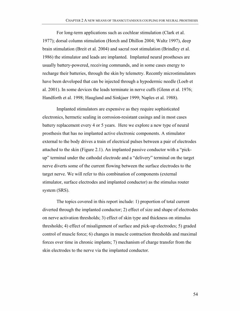
CHAPTER 2 A NEW MEANS OF TRANSCUTANEOUS COUPLING FOR NEURAL PROSTHESIS
For long-term applications such as cochlear stimulation (Clark et al.
1977); dorsal column stimulation (Horch and Dhillon 2004; Waltz 1997), deep
brain stimulation (Breit et al. 2004) and sacral root stimulation (Brindley et al.
1986) the stimulator and leads are implanted. Implanted neural prostheses are
usually battery-powered, receiving commands, and in some cases energy to
recharge their batteries, through the skin by telemetry. Recently microstimulators
have been developed that can be injected through a hypodermic needle (Loeb et
al. 2001). In some devices the leads terminate in nerve cuffs (Glenn et al. 1976;
Handforth et al. 1998; Haugland and Sinkjaer 1999; Naples et al. 1988).
Implanted stimulators are expensive as they require sophisticated
electronics, hermetic sealing in corrosion-resistant casings and in most cases
battery replacement every 4 or 5 years. Here we explore a new type of neural
prosthesis that has no implanted active electronic components. A stimulator
external to the body drives a train of electrical pulses between a pair of electrodes
attached to the skin (Figure 2.1). An implanted passive conductor with a “pick-
up” terminal under the cathodal electrode and a “delivery” terminal on the target
nerve diverts some of the current flowing between the surface electrodes to the
target nerve. We will refer to this combination of components (external
stimulator, surface electrodes and implanted conductor) as the stimulus router
system (SRS).
The topics covered in this report include: 1) proportion of total current
diverted through the implanted conductor; 2) effect of size and shape of electrodes
on nerve activation thresholds; 3) effect of skin type and thickness on stimulus
thresholds; 4) effect of misalignment of surface and pick-up electrodes; 5) graded
control of muscle force; 6) changes in muscle contraction thresholds and maximal
forces over time in chronic implants; 7) mechanism of charge transfer from the
skin electrodes to the nerve via the implanted conductor.
54
CHAPTER 2 A NEW MEANS OF TRANSCUTANEOUS COUPLING FOR NEURAL PROSTHESIS
Figure 2.1: Schematic of the stimulus router system. A) Cutaway view showing the cathodal surface electrode, implanted pick-up electrode, passive conductor and nerve cuff. B) Cross-section showing current flowing between the surface electrodes, some being diverted through the implanted conductor to the nerve cuff and returning via forearm tissues.
2.2 Methods
As we were studying a completely new way of delivering stimulation to
nerves, our study was exploratory in nature. To characterize the electrical and
functional properties of the SRS across a variety of skin types, acute non-recovery
experiments were performed in four cats, four rabbits and a Duroc piglet. In
addition, passive conductors were implanted chronically in three cats and their
operation as part of an SRS was monitored for several months. All experiments
were performed with the approval of the University of Alberta Health Sciences
Animal Policy and Welfare Committee. The human perceptual threshold
measurements were carried out under a protocol approved by the University of
Alberta Health Research Ethics Board.
SRS designs: External stimulators, surface electrodes and nerve cuffs are
conventional components of the SRS that have been widely discussed in the
literature (Horch and Dhillon 2004). The novel component of the SRS is the
55
CHAPTER 2 A NEW MEANS OF TRANSCUTANEOUS COUPLING FOR NEURAL PROSTHESIS
subcutaneous terminal that “picks up” some of the current flowing between a pair
of surface electrodes and delivers it through an insulated wire to a nerve. In our
study, we used conventional external components and nerve cuffs and explored
various shapes and sizes of pick-up terminal.
Surface electrodes: these consisted of pairs of self-adhesive conductive
gel surface electrodes, 34x23 mm with a 10 mm diameter central terminal
(Kendall Soft-E; The Kendall Company, Mansfield, Massachusetts) affixed to the
closely-shaved skin, well away from the target nerve and muscle, usually on the
back . The anodal surface electrode was typically placed on the skin 30 to 50 mm
away from the cathodal surface electrode.
Implanted conductors: In acute experiments, the pick-up terminals
included discs or rectangles of stainless steel or bared lengths of Cooner AS814
lead wire coiled tightly around 2/0 prolene suture thread (Ethicon, Inc.,
Somerville New Jersey), similar to the termination of the “Peterson” electrode
(Peterson et al. 1994). In chronic experiments, only stainless steel discs were
used. Dimensions are given in Results. In all cases, delivery terminals (nerve
cuffs) consisted of an 8x10 mm piece of stainless-steel mesh (8 counts/mm:
Stainless Mesh; Continental Wire Cloth Corp., Edmonton, Alberta) within a 12
mm long, longitudinally slit silastic tube (3.4 mm inside diameter, 4.7 mm outside
diameter; Dow Corning Corp., MI). In acute experiments, pick-up terminals were
placed subcutaneously under the cathodal surface electrode through a small
incision, usually about 10 mm away.
Stimulators: Depending on the experiment, one of two stimulators was
used to deliver stimulus pulse trains (the independent variable) between the
surface electrodes. The first was a custom stimulator that provided an amplitude-
modulated train of biphasic, constant-current pulses (350 µs primary phase
duration, 45 pulses/s). The second was a Grass SD9 stimulator (Grass
Instruments, Rhode Island) that produced voltage-controlled pulses (300 µs
duration, 60 pulses/s).
56
CHAPTER 2 A NEW MEANS OF TRANSCUTANEOUS COUPLING FOR NEURAL PROSTHESIS
“Internal” versus “total” current: The current delivered through the
surface electrodes (“total current”: Itotal) was measured indirectly by measuring
the voltage across a 100 ohm resistor in series with the negative output of the
stimulator and the cathodal surface electrode. In acute experiments only, the
current in the implanted conductor (“internal” or “router” current, Irouter) was
likewise measured: the pick-up and delivery terminals were supplied with
separate insulated leads, which were brought out through the skin and attached to
each end of the 100 ohm series resistor with miniature connectors.
Amplifiers: Three ISO-DAM8A differential amplifiers (World Precision
Instruments Inc., Florida) were used to measure the voltage 1) between the
surface electrodes, 2) across the 100 ohm resistor in series with the cathodal
surface electrode, 3) across the 100 ohm resistor in series with the pick-up and
delivery terminals. All three signals were band-pass filtered (1Hz – 10KHz). The
amplified signals were monitored with a Tektronix 5111 storage oscilloscope
(Tektronix Inc., Texas) and digitized at 25,000 samples/sec with a CED 1401
laboratory computer interface (Cambridge Electronic Design Inc., Cambridge
UK).
Force transducer: The force produced by the activated muscles was
measured with a custom proving-ring strain gauge transducer attached by a
Velcro loop around the metatarso-phalangeal joint (Figure 2.5C). The lower part
of the animal’s leg was stabilized with respect to the transducer with a padded
clamp fixed just above the ankle joint. During maximal muscle contractions the
middle of the foot at the point of attachment of the loop moved by an estimated 2
to 3mm due to the compliance of the soft tissue and the loop. Torque was
calculated from the force and the distance between the ankle joint and the point of
application of the Velcro loop.
Surgical procedures: In all animals, the gaseous anesthetic isoflurane
(Forane; Baxter Corp., Toronto, Ontario) was used to induce and maintain
anesthesia. Respiration was monitored with a Beeper Animal Respiration monitor
(Spencer Instrumentation, Irvine, Ca) and pulse rate was monitored with a
57
CHAPTER 2 A NEW MEANS OF TRANSCUTANEOUS COUPLING FOR NEURAL PROSTHESIS
SurgiVet V3404 pulse oximeter (SurgiVet, Waukesha, WI). A feedback-
controlled heating pad under the animal was used to maintain body temperature.
The depth of anesthesia was monitored periodically by checking respiratory rate,
heart rate and motor responses to strong pinches applied to the toes.
In the case of the acute experiments, after deep anesthesia was achieved, a
tracheotomy was performed and an endotracheal tube was inserted to allow
automatic control of ventilation with a Model A.D.S. 1000 veterinary anesthesia
delivery system (Engler Eng. Corp., Fl.). An intravenous cannula was inserted
into the jugular vein. Acute experiments typically lasted 12 hours, after which the
animal was euthanized with intravenous sodium pentobarbital.
Three cats were chronically implanted with passive conductors. The
surgery, which lasted about an hour, was performed under aseptic conditions in a
fully-equipped operating room. Pre-operatively the animals were sedated with
intramuscular acetylpromazine (0.25mg/Kg) and atropine (0.04mg/kg). Isoflurane
anesthesia was induced via a mask and maintained via a pediatric endotracheal
tube. Respiration, heart rate and depth of anesthesia were monitored as described
above. The legs and back were closely shaved, cleaned with soap and swabbed
with iodine solution. An intravenous catheter was inserted into the cephalic vein
and an intravenous drip of isotonic saline was implemented. About 10 mm of the
common peroneal nerve was exposed proximal to the knee. The nerve cuff was
placed on it and sutured closed at each end with 6/0 prolene monofilament
sutures. The pick-up terminal and connecting lead were tunneled under the skin
to a site over the sacrum. A small hole in the pick-up terminal allowed it to be
sutured to the lumbodorsal fascia with 3/0 prolene monofilament suture. The two
skin incisions were sutured with 3/0 prolene. Post-operative analgesia was
provided with subcutaneous ketoprofen (Anafen, Merial Canada, Inc., Quebec
City, Quebec) and a fentanyl patch (Duragesic 25, Janssen-Ortho, Inc., Toronto,
Ontario). Post-operative recovery took place in an intensive care unit. Ampicillin
was administered for 2-4 days after surgery, followed by Amoxil (50 mg tablets,
2/day) for 6 additional days.
58
CHAPTER 2 A NEW MEANS OF TRANSCUTANEOUS COUPLING FOR NEURAL PROSTHESIS
In the weeks and months after recovery, stimulus thresholds and maximal
force measurements were performed during brief periods of isoflurane anesthesia.
Initially this was done at weekly intervals, then bi-weekly.
2.3 Results
2.3.1 Proportion of total current diverted and effect of shape of pick-up electrodes on nerve activation thresholds
As anticipated, the ratio of internal current Irouter in the implanted
conductor to total external current Itotal depended on the surface area of the pick-
up electrode. Figure 2.2A shows data from an experiment performed in an 11.5
Kg Duroc piglet. As above, two conductive gel electrodes were placed 5 cm apart
on the closely shaved skin of the piglet’s back at mid-thoracic level. A Grass SD9
stimulator was used to deliver stimulus pulse trains. Pick-up electrodes of
different surface areas and designs were tested sequentially by slipping them
subcutaneously under the cathodal surface electrode and connecting their lead
wire to that of the 8x10 mm stainless steel mesh terminal in a cuff on the common
peroneal nerve.
Three types of pick-up terminal were tested: discs, rectangles and coils of
bared lead wire wound tightly around a 2/0 prolene suture thread (Peterson et al.
1994; Prochazka and Davis 1992). We will refer to the latter as “Peterson-type”
electrodes. Total external current and voltage between the surface electrodes as
well as internal current flowing through the implanted conductor were monitored
(Methods). Each data point in Figure 2.2A shows the ratio of internal current to
total current (Irouter /Itotal) for a given area of pick-up electrode. The ratio was
approximately 0.2 for surface areas greater than 1 cm2. Thus in this case about
20% of the total current was diverted through the implanted conductor.
59
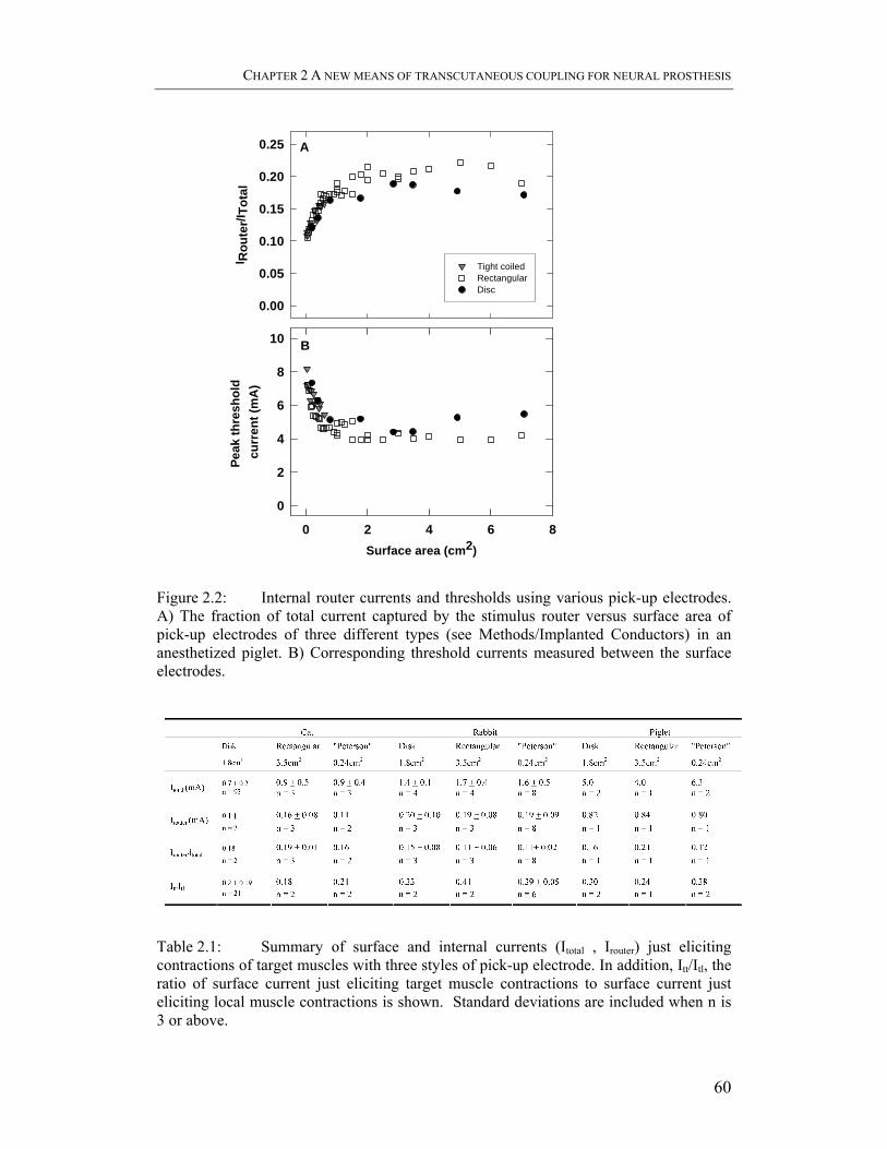
CHAPTER 2 A NEW MEANS OF TRANSCUTANEOUS COUPLING FOR NEURAL PROSTHESIS
B
Surface area (cm2)0 2 4 6 8
Peak
thre
shol
d cu
rren
t (m
A)
0
2
4
6
8
10
A
I Rou
ter/I
Tota
l
0.00
0.05
0.10
0.15
0.20
0.25
Tight coiledRectangularDisc
Figure 2.2: Internal router currents and thresholds using various pick-up electrodes. A) The fraction of total current captured by the stimulus router versus surface area of pick-up electrodes of three different types (see Methods/Implanted Conductors) in an anesthetized piglet. B) Corresponding threshold currents measured between the surface electrodes.
Table 2.1: Summary of surface and internal currents (Itotal , Irouter) just eliciting contractions of target muscles with three styles of pick-up electrode. In addition, Itt/Itl, the ratio of surface current just eliciting target muscle contractions to surface current just eliciting local muscle contractions is shown. Standard deviations are included when n is 3 or above.
60
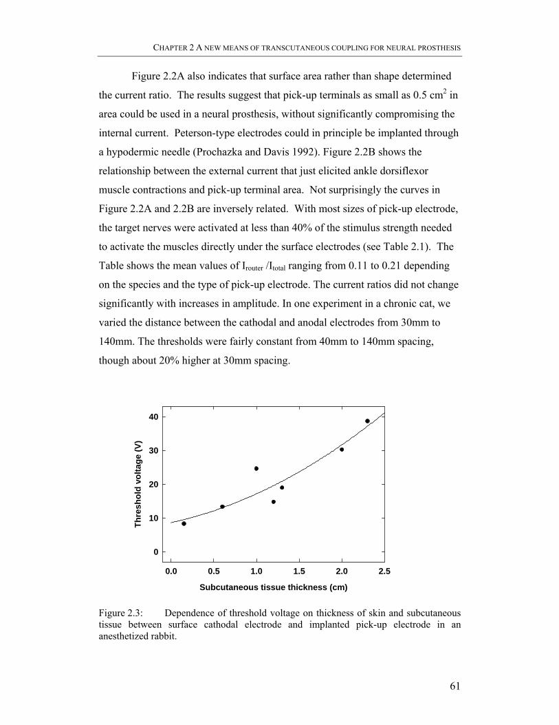
CHAPTER 2 A NEW MEANS OF TRANSCUTANEOUS COUPLING FOR NEURAL PROSTHESIS
Figure 2.2A also indicates that surface area rather than shape determined
the current ratio. The results suggest that pick-up terminals as small as 0.5 cm2 in
area could be used in a neural prosthesis, without significantly compromising the
internal current. Peterson-type electrodes could in principle be implanted through
a hypodermic needle (Prochazka and Davis 1992). Figure 2.2B shows the
relationship between the external current that just elicited ankle dorsiflexor
muscle contractions and pick-up terminal area. Not surprisingly the curves in
Figure 2.2A and 2.2B are inversely related. With most sizes of pick-up electrode,
the target nerves were activated at less than 40% of the stimulus strength needed
to activate the muscles directly under the surface electrodes (see Table 2.1). The
Table shows the mean values of Irouter /Itotal ranging from 0.11 to 0.21 depending
on the species and the type of pick-up electrode. The current ratios did not change
significantly with increases in amplitude. In one experiment in a chronic cat, we
varied the distance between the cathodal and anodal electrodes from 30mm to
140mm. The thresholds were fairly constant from 40mm to 140mm spacing,
though about 20% higher at 30mm spacing.
Subcutaneous tissue thickness (cm)
0.0 0.5 1.0 1.5 2.0 2.5
Thre
shol
d vo
ltage
(V)
0
10
20
30
40
Figure 2.3: Dependence of threshold voltage on thickness of skin and subcutaneous tissue between surface cathodal electrode and implanted pick-up electrode in an anesthetized rabbit.
61
CHAPTER 2 A NEW MEANS OF TRANSCUTANEOUS COUPLING FOR NEURAL PROSTHESIS
2.3.2 Effect of skin thickness and skin type on stimulus thresholds
In one cat experiment we found that stimulus thresholds varied less than
30% across a range of skin thicknesses from 1.0 mm to 5.0 mm. Similarly, in a
rabbit experiment a Peterson-type pick-up electrode was placed under different
thicknesses of subcutaneous fat and muscle tissue in the groin area (Figure 2.3).
The regression line fitted to these data (r2=0.98) indicated that in the range 1.0
mm to 5.0 mm, the threshold increased by 31.9 %.
2.3.3 Effect of misalignment of surface and pick-up electrodes
It is to be expected that in clinical use, cathodal electrodes may not always
be placed accurately over corresponding implanted pick-up electrodes.
Furthermore, it is conceivable that systems with matching and accurately aligned
arrays of surface and pick-up electrodes could stimulate several nerves
independently with interleaved pulse trains. It was therefore of interest to
determine the relationship between the surface current required to elicit a muscle
contraction and the distance between the centres of the surface cathodal electrode
and the underlying pick-up electrode. We explored this in two rabbits, two cats
and a piglet anesthetized with isoflurane. Figure 2.4 shows four such sets of
measurements, two in an acute cat experiment, one in a chronically implanted cat
and the other in an acute rabbit experiment. In the rabbit, the pick-up electrode
was a 10 mm long Peterson-type terminal (0.24 cm2 surface area), in the
chronically implanted cat, it was a 15 mm diameter disk (1.8 cm2 surface area),
and in the acute cat experiment both types of pick up electrode were used. The
surface anodal electrodes were Kendall Soft-E self-adhesive conductive gel
electrodes, 34x23 mm with a 10 mm diameter central carbon terminal. The same
gel electrodes, cut down to a diameter of 15 mm, served as the surface cathodal
electrodes. A fresh electrode was used for each cathodal position.
62
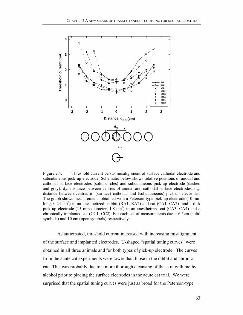
CHAPTER 2 A NEW MEANS OF TRANSCUTANEOUS COUPLING FOR NEURAL PROSTHESIS
Distance, dcp (cm)
-3 -2 -1 0 1 2 3
Thre
shol
d cu
rren
t (m
A)
0
1
2
3
4
RA1RA2CA1CA2CA3CA4CC1CC2
dac
dcp +-
Figure 2.4: Threshold current versus misalignment of surface cathodal electrode and subcutaneous pick-up electrode. Schematic below shows relative positions of anodal and cathodal surface electrodes (solid circles) and subcutaneous pick-up electrode (dashed and gray). dac: distance between centres of anodal and cathodal surface electrodes, dcp: distance between centres of (surface) cathodal and (subcutaneous) pick-up electrodes. The graph shows measurements obtained with a Peterson-type pick-up electrode (10 mm long, 0.24 cm2) in an anesthetized rabbit (RA1, RA2) and cat (CA1, CA2) and a disk pick-up electrode (15 mm diameter, 1.8 cm2) in an anesthetized cat (CA3, CA4) and a chronically implanted cat (CC1, CC2). For each set of measurements dac = 6.5cm (solid symbols) and 10 cm (open symbols) respectively.
As anticipated, threshold current increased with increasing misalignment
of the surface and implanted electrodes. U-shaped “spatial tuning curves” were
obtained in all three animals and for both types of pick-up electrode. The curves
from the acute cat experiments were lower than those in the rabbit and chronic
cat. This was probably due to a more thorough cleansing of the skin with methyl
alcohol prior to placing the surface electrodes in the acute cat trial. We were
surprised that the spatial tuning curves were just as broad for the Peterson-type
63
CHAPTER 2 A NEW MEANS OF TRANSCUTANEOUS COUPLING FOR NEURAL PROSTHESIS
pick-up electrodes as for the disks. It may be that the width of tuning curves
depends more on the size of the surface electrodes than the implanted pick-up
electrodes. The narrower the tuning curve, the closer the possible spacing of
neighbouring electrodes in a multi-channel array.
2.3.4 Graded control of nerve activation levels
To be useful as a neural prosthesis, the system should allow graded
activation of nerves over the full physiological range, ideally without activating
nerves innervating non-targeted muscles directly under the surface electrodes.
Figure 2.5 shows the force developed by the ankle dorsiflexor muscles of a cat in
response to an amplitude-modulated pulse train delivered by the custom
stimulator through a pair of surface electrodes placed 5 cm apart. The cathodal
electrode was located on the shaved skin of the sacrum over a subcutaneous pick-
up electrode (15 mm dia. disc) connected by a lead wire to a nerve cuff implanted
23 weeks before on the common peroneal nerve. The force produced by the ankle
dorsiflexor muscles was measured at the metatarso-phalangeal joint (Methods).
Force began to rise when the amplitude of the current pulses delivered
through the surface electrodes reached 0.6 mA (Figure 2.5A). We will call this
parameter the threshold current Ith. With further increases in stimulus amplitude,
force reached a maximum, Fmax at a current of Imax. Between 0.65 mA and 0.8 mA
amplitude, force increased monotonically, showing that the neural prosthetic
requirement of controlled gradation of force is achievable. Close observation of
the tissues under and around the surface electrodes indicated that no non-targeted
muscle contractions occurred at any time during the recording. The ratio Imax/Ith
(stimulus current eliciting maximal force/stimulus current just eliciting a
contraction) was measured systematically over several months in 2 cats, each with
two chronically implanted router systems. Mean Ith was 0.72 + 0.20 mA S.D. (n =
88) and mean Imax was 1.30 + 0.45 mA S.D. (n = 82), giving a Imax/Ith ratio of 1.8.
Figure 2.5 is typical of hundreds of measurements we have made in four different
64
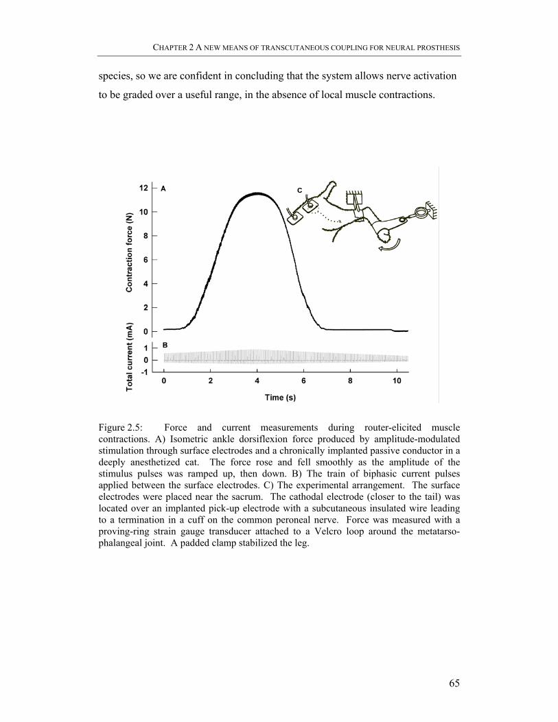
CHAPTER 2 A NEW MEANS OF TRANSCUTANEOUS COUPLING FOR NEURAL PROSTHESIS
species, so we are confident in concluding that the system allows nerve activation
to be graded over a useful range, in the absence of local muscle contractions.
Figure 2.5: Force and current measurements during router-elicited muscle contractions. A) Isometric ankle dorsiflexion force produced by amplitude-modulated stimulation through surface electrodes and a chronically implanted passive conductor in a deeply anesthetized cat. The force rose and fell smoothly as the amplitude of the stimulus pulses was ramped up, then down. B) The train of biphasic current pulses applied between the surface electrodes. C) The experimental arrangement. The surface electrodes were placed near the sacrum. The cathodal electrode (closer to the tail) was located over an implanted pick-up electrode with a subcutaneous insulated wire leading to a termination in a cuff on the common peroneal nerve. Force was measured with a proving-ring strain gauge transducer attached to a Velcro loop around the metatarso-phalangeal joint. A padded clamp stabilized the leg.
65
CHAPTER 2 A NEW MEANS OF TRANSCUTANEOUS COUPLING FOR NEURAL PROSTHESIS
2.3.5 Muscle contraction thresholds and maximal torques in chronic implants
In any clinical application, reproducibility and reliability of nerve
activation are crucial. At the initial stage of the chronic implants, breakage of
wires occurred within 2-3 weeks after implantation. These early prototype
systems were fabricated with Cooner AS632 lead wires. They were then removed
in an aseptic surgical procedure as described in Methods and replaced with
implants made with Cooner AS632 lead wires reinforced with 4-0 prolene sutures,
and in one case, a thicker Cooner AS814 lead wire. We measured Ith, Imax and
maximal torque (τmax) in 3 cats implanted with a total of 6 router systems for up to
36 weeks (Figures 2.6A, 2.6B and 2.6C). Interestingly, Ith and Imax gradually
decreased over the first 50 or 60 days as reported in previous nerve cuff data
(Grill and Mortimer 1995) and τmax slightly increased. Two of the prolene
reinforced AS632 router wires failed after a few weeks, while the rest remained
functional for up to 8 months.
Consecutive torque values in any given animal in Figure 2.6C varied
substantially. We therefore did control measurements in which an anesthetized
cat was placed into and removed from the force recording arrangement ten
consecutive times. A force of 8N was applied with a spring gauge through a 4 mm
diameter cord tied firmly around the foot 30mm from the ankle joint (torque =
0.24 Nm). In each trial the 30 mm wide Velcro strap used in the force
measurements of Figure 2.6C was newly attached around the metatarsal
phalangeal joint. The distance of the centre of this strap from the ankle joint was
found to vary between 50 and 65 mm in these trials, a similar range as in the
chronic measurements. The proving ring force transducer was attached to the
Velcro strap as in Figure 2.5. The mean torque thus measured was 0.31 + 0.03
Nm S.D., which only partly explains the inter-trial variability in Figure 2.6C. The
additional variability was probably due to muscle fatigue, as the number of
contractions needed to establish the stimulus level required to elicit peak force
varied from day to day.
66

CHAPTER 2 A NEW MEANS OF TRANSCUTANEOUS COUPLING FOR NEURAL PROSTHESIS
A
Tota
l thr
esho
ld
curr
ent (
mA
)
0.0
0.5
1.0
1.5
B
Cur
rent
at m
axim
al
torq
ue (m
A)
0.0
1.0
2.0
3.0
4.0
C
Time (days)
0 50 100 150 200 250
Max
imal
torq
ue (N
m)
0.0
0.2
0.4
0.6
0.8
1.0
1.2
Figure 2.6: Stimulus parameters monitored periodically over 250 days in 6 implanted stimulus router systems in 3 cats. Each system represented by a symbol with connecting lines. A) Current at muscle activation threshold Ith, B) Current at maximal torque Imax, C) Maximal isometric torque τmax. Two implants fabricated with thin lead wires failed 13 and 48 days after implantation respectively. Each plot has a superimposed thick line of best fit (exponential functions in A and B, linear in C).
67
CHAPTER 2 A NEW MEANS OF TRANSCUTANEOUS COUPLING FOR NEURAL PROSTHESIS
2.3.6 Mechanism of charge transfer via the implanted conductor
The question arose as to whether the current flowing in the implanted
conductor is capacitively or resistively coupled. Also whether the electrical
properties of different skin types (e.g. dry versus oily skin) influence charge
transfer and therefore the viability of the system as a neural prosthesis. Figure 2.7
shows voltage and current waveforms measured in cat, rabbit and piglet in the
course of the experiments described above. The voltage profiles were damped
rectangular waves. The current profiles show an initial peak, followed by an
exponential sag towards an asymptotic level. The electrical properties of tissue are
nonlinear, but to a first approximation, the greater the sag in current, the greater
the ratio of capacitive to resistive current (Reilly 1992). Although there were
significant differences between corresponding voltage and current profiles, there
was little difference between corresponding pairs of current profiles, indicating
that most of the capacitance was at the interfaces between the surface electrodes
and skin. In an additional experiment, voltage pulses were applied between a
pick-up electrode and a separate delivery electrode placed subcutaneously a few
cm from each other, with leads emerging percutaneously and connected to the
anode and cathode of the stimulator respectively. The current in this case sagged
by less than 5%, supporting the idea that the interfaces with subcutaneous tissues
are largely resistive.
It follows that the rise time of current delivered to the nerve will in general
be similar to that delivered to the local subcutaneous tissues under the surface
electrodes. This in turn means that the relative thresholds of activation of target
and local nerves will be preserved, even in the face of variations in the
capacitance of the skin interface. This was in fact borne out by the similar
relative thresholds of local and targeted contractions we observed across different
species, skin thicknesses, skin types and variations in thickness of subcutaneous
fat.
68
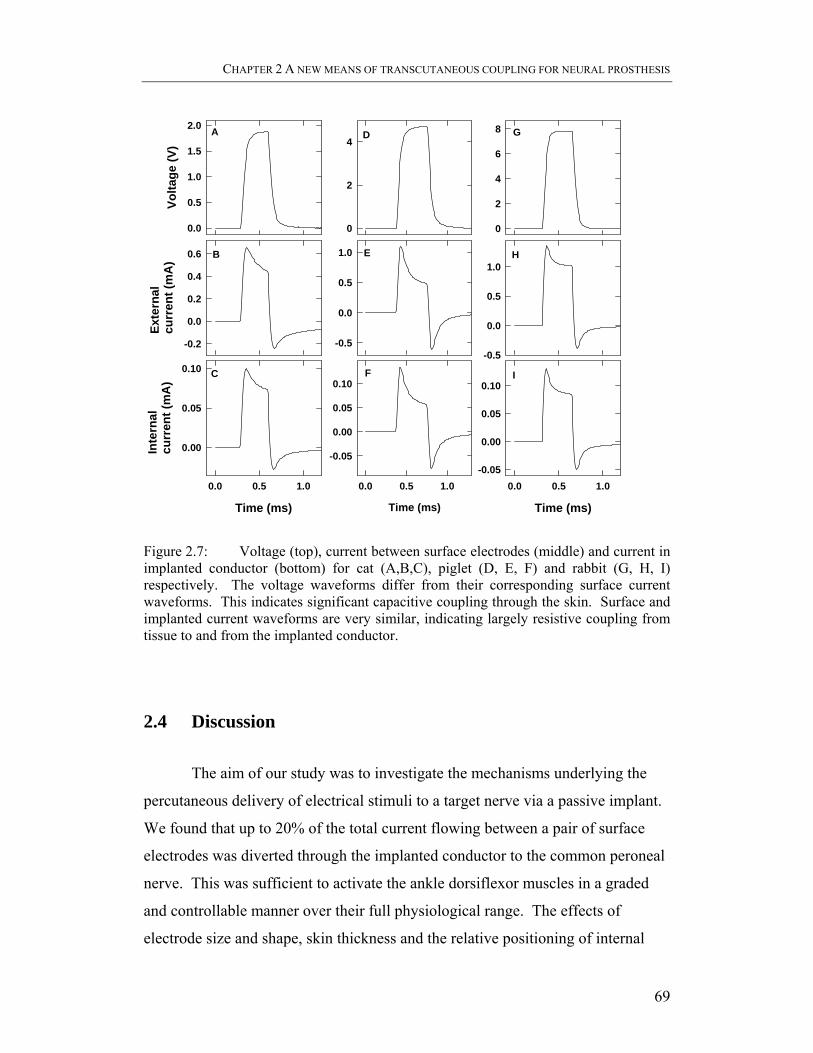
CHAPTER 2 A NEW MEANS OF TRANSCUTANEOUS COUPLING FOR NEURAL PROSTHESIS
A
Volta
ge (V
)
0.0
0.5
1.0
1.5
2.0
B
X Data
Exte
rnal
cu
rren
t (m
A)
-0.2
0.0
0.2
0.4
0.6
C
Time (ms)
0.0 0.5 1.0
Inte
rnal
cu
rren
t (m
A)
0.00
0.05
0.10
G
0
2
4
6
8
H
-0.5
0.0
0.5
1.0
I
Time (ms)
0.0 0.5 1.0-0.05
0.00
0.05
0.10
D
0
2
4
E
-0.5
0.0
0.5
1.0
F
Time (ms)
0.0 0.5 1.0
-0.05
0.00
0.05
0.10
Figure 2.7: Voltage (top), current between surface electrodes (middle) and current in implanted conductor (bottom) for cat (A,B,C), piglet (D, E, F) and rabbit (G, H, I) respectively. The voltage waveforms differ from their corresponding surface current waveforms. This indicates significant capacitive coupling through the skin. Surface and implanted current waveforms are very similar, indicating largely resistive coupling from tissue to and from the implanted conductor.
2.4 Discussion
The aim of our study was to investigate the mechanisms underlying the
percutaneous delivery of electrical stimuli to a target nerve via a passive implant.
We found that up to 20% of the total current flowing between a pair of surface
electrodes was diverted through the implanted conductor to the common peroneal
nerve. This was sufficient to activate the ankle dorsiflexor muscles in a graded
and controllable manner over their full physiological range. The effects of
electrode size and shape, skin thickness and the relative positioning of internal
69
CHAPTER 2 A NEW MEANS OF TRANSCUTANEOUS COUPLING FOR NEURAL PROSTHESIS
and external electrode terminals on nerve activation thresholds were quantified.
The reproducibility of muscle activation with chronically implanted systems was
studied over several months. A comparison of external and internal current and
voltage profiles led us to conclude that the skin interface had a large capacitive
component of impedance, whereas the interfaces between the terminals of the
implanted conductor and surrounding tissues were largely resistive. The results
also indicated that although variations in skin impedance affected the rise times of
current and voltage, in all cases the thresholds of activation of target motor nerves
were lower than the thresholds for activating motor nerves directly under the
surface electrodes. We did not attempt to monitor whether cutaneous nerves were
activated in these experiments. It is possible in a human clinical application that
some sensation would occur as a result of activation of cutaneous nerves under
the surface electrodes, particularly with the large pulse amplitudes that may be
required to activate the target nerves strongly. To explore this possibility, in a
separate set of measurements we determined the sensory perceptual thresholds to
surface stimulation with the same electrodes in five healthy human subjects (age
range 23 to 59, 4 males, 1 female). After cleaning the skin with alcohol, the
cathodal electrode was placed over the median nerve just proximal to the wrist
crease and the anodal electrode was placed on the corresponding posterior surface
of the wrist. Brief bursts of pulses (monophasic, 300 µs duration, 60 pulses/s)
were delivered by the Grass stimulator at varying amplitudes and subjects were
required to report any sensations. The perceptual thresholds ranged from 3.8 to
4.4 mA (mean 4.1 mA). The motor thresholds across all the animal experiments in
Table 2.1 range from 0.7 mA to 6.3 mA. It remains to be seen whether the same
range of stimulus amplitudes that produced appreciable muscle forces in the
animals in our study is similarly effective in humans implanted with router
systems. We have found that in human subjects using surface stimulators such as
the WalkAide and Bionic Glove (Dai et al. 1996; Prochazka et al. 1997),
cutaneous sensations generally accompany muscle contractions, and they are
usually well tolerated. Assuming that the levels of surface stimulation needed to
70
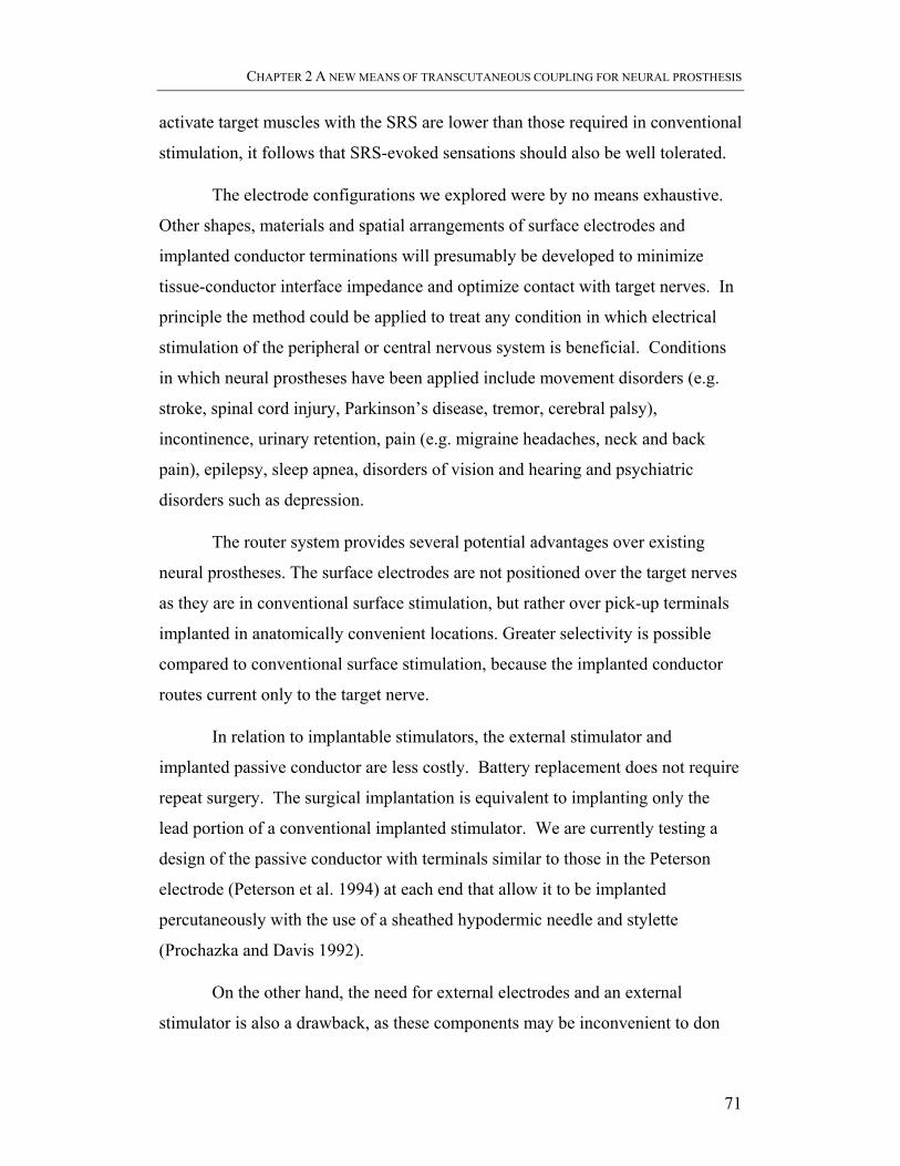
CHAPTER 2 A NEW MEANS OF TRANSCUTANEOUS COUPLING FOR NEURAL PROSTHESIS
activate target muscles with the SRS are lower than those required in conventional
stimulation, it follows that SRS-evoked sensations should also be well tolerated.
The electrode configurations we explored were by no means exhaustive.
Other shapes, materials and spatial arrangements of surface electrodes and
implanted conductor terminations will presumably be developed to minimize
tissue-conductor interface impedance and optimize contact with target nerves. In
principle the method could be applied to treat any condition in which electrical
stimulation of the peripheral or central nervous system is beneficial. Conditions
in which neural prostheses have been applied include movement disorders (e.g.
stroke, spinal cord injury, Parkinson’s disease, tremor, cerebral palsy),
incontinence, urinary retention, pain (e.g. migraine headaches, neck and back
pain), epilepsy, sleep apnea, disorders of vision and hearing and psychiatric
disorders such as depression.
The router system provides several potential advantages over existing
neural prostheses. The surface electrodes are not positioned over the target nerves
as they are in conventional surface stimulation, but rather over pick-up terminals
implanted in anatomically convenient locations. Greater selectivity is possible
compared to conventional surface stimulation, because the implanted conductor
routes current only to the target nerve.
In relation to implantable stimulators, the external stimulator and
implanted passive conductor are less costly. Battery replacement does not require
repeat surgery. The surgical implantation is equivalent to implanting only the
lead portion of a conventional implanted stimulator. We are currently testing a
design of the passive conductor with terminals similar to those in the Peterson
electrode (Peterson et al. 1994) at each end that allow it to be implanted
percutaneously with the use of a sheathed hypodermic needle and stylette
(Prochazka and Davis 1992).
On the other hand, the need for external electrodes and an external
stimulator is also a drawback, as these components may be inconvenient to don
71
CHAPTER 2 A NEW MEANS OF TRANSCUTANEOUS COUPLING FOR NEURAL PROSTHESIS
and doff and to wear in daily life. It is worth pointing out that implanted neural
prostheses requiring commands from outside the body also require external
controllers and coil antennas. In applications requiring continuous long-term
stimulation with pre-set pulse parameters, fully implanted neural prostheses will
presumably remain the devices of choice.
Some existing implantable neural prostheses are able to activate several
target nerves independently (Loeb et al. 2001), so the question arises whether
router systems could also have this capability. The spatial tuning curves of Figure
2.4 show that thresholds doubled for misalignments of surface and pick-up
electrodes of around 2 cm. Given our finding that muscles were fully recruited at
a mean stimulus current 1.8 times that at threshold, this suggests that surface
electrodes could be spaced 2 cm apart without causing cross-talk. Two or three
separate muscles could therefore be controlled independently using separate pick-
up electrodes in the wristwatch-like configuration in Figure 2.1. Larger numbers
of independent channels might be feasible with larger matrices of surface
electrodes and matching pick-up electrodes, though again this might be better
done with conventional neural prostheses.
It should also be pointed out that if surface electrodes are not attached
properly, or if they dry out, the current supplied by a constant-current stimulator
flows through a reduced volume of skin, with an increase in the local current
density and electric field such that cutaneous receptors including nociceptors may
be activated, causing discomfort and pain.
In conclusion, this study is the first to explore in detail the electrical and
functional properties of a new means of selectively activating nerves by
transcutaneous coupling of stimulus pulses via an implanted passive conductor.
We believe that the technique and the results reported here provide the basis for a
new family of neural prostheses that will complement existing types.
72
CHAPTER 2 A NEW MEANS OF TRANSCUTANEOUS COUPLING FOR NEURAL PROSTHESIS
2.5 Acknowledgements
This work was supported by the Canadian Institutes of Health Research
and the Alberta Heritage Foundation for Medical Research. We thank Mr. Jan
Kowalczewski for the artwork in Figure 2.1. We also thank the members of the
Health Sciences Animal Laboratory Services at the University of Alberta for the
diligent care of the animals involved in the study.
2.6 References
Breit S, Schulz JB, and Benabid AL. Deep brain stimulation. Cell Tissue Res 318: 275-288, 2004.
Brindley GS, Polkey CE, Rushton DN, and Cardozo L. Sacral anterior root stimulators for bladder control in paraplegia: the first 50 cases. J Neurol Neurosurg Psychiatry 49: 1104-1114, 1986.
Clark GM, Tong YC, Black R, Forster IC, Patrick JF, et al. A multiple electrode cochlear implant. J Laryngol Otol 91: 935-945, 1977.
Dai R, Stein RB, Andrews BJ, James KB, and Wieler M. Application of tilt sensors in functional electrical stimulation. IEEE Trans Rehabil Eng 4: 63-72, 1996.
Duchenne G-B. Physiology of Motion Demonstrated by Means of Electrical Stimulation and Clinical Observation and Applied to the Study of Paralysis and Deformities. Philadelphia, PA: Sounders, 1867.
Glenn WW, Holcomb WG, Shaw RK, Hogan JF, and Holschuh KR. Long-term ventilatory support by diaphragm pacing in quadriplegia. Ann Surg 183: 566-577, 1976.
Grill WM, and Mortimer JT. Temporal stability of nerve cuff electrode recruitment properties. In: IEEE 17th Annual Conference, Engineering in Medicine and Biology Society1995.
Handforth A, DeGiorgio CM, Schachter SC, Uthman BM, Naritoku DK, et al. Vagus nerve stimulation therapy for partial-onset seizures: a randomized active-control trial. Neurology 51: 48-55, 1998.
73

CHAPTER 2 A NEW MEANS OF TRANSCUTANEOUS COUPLING FOR NEURAL PROSTHESIS
Haugland M, and Sinkjaer T. Interfacing the body's own sensing receptors into neural prosthesis devices. Technol Health Care 7: 393-399, 1999.
Horch KW, and Dhillon GS editors. Neuroprosthetics. Theory and Practice. River Edge, NJ: World Scientific, 2004.
Liberson WT, Holmquest HJ, Scot D, and Dow M. Functional electrotherapy: stimulation of the peroneal nerve synchronized with the swing phase of the gait of hemiplegic patients. Arch Phys Med Rehabil 42: 101-105, 1961.
Loeb GE, Peck RA, Moore WH, and Hood K. BION system for distributed neural prosthetic interfaces. Med Eng Phys 23: 9-18, 2001.
Marsolais EB, and Kobetic R. Implantation techniques and experience with percutaneous intramuscular electrodes in the lower extremities. J Rehabil Res Dev 23: 1-8, 1986.
Naples GG, Mortimer JT, Scheiner A, and Sweeney JD. A spiral nerve cuff electrode for peripheral nerve stimulation. IEEE Trans Biomed Eng 35: 905-916, 1988.
Peckham PH, Marsolais EB, and Mortimer JT. Restoration of key grip and release in the C6 tetraplegic patient through functional electrical stimulation. J Hand Surg [Am] 5: 462-469, 1980.
Peterson DK, Nochomovitz ML, Stellato TA, and Mortimer JT. Long-term intramuscular electrical activation of the phrenic nerve: efficacy as a ventilatory prosthesis. IEEE Trans Biomed Eng 41: 1127-1135, 1994.
Prochazka A, and Davis LA. Clinical experience with reinforced, anchored intramuscular electrodes for functional neuromuscular stimulation. J Neurosci Methods 42: 175-184, 1992.
Prochazka A, Gauthier M, Wieler M, and Kenwell Z. The bionic glove: an electrical stimulator garment that provides controlled grasp and hand opening in quadriplegia. Arch Phys Med Rehabil 78: 608-614, 1997.
Reilly J. Electrical stimulation and electropathology. Cambridge: Cambridge University Press, 1992.
Vodovnik L. Therapeutic effects of functional electrical stimulation of extremities. Med Biol Eng Comput 19: 470-478, 1981.
Waltz JM. Spinal cord stimulation: a quarter century of development and investigation. A review of its development and effectiveness in 1,336 cases. Stereotact Funct Neurosurg 69: 288-299, 1997.
74
Chapter 3
Properties of the stimulus router system, a novel neural prosthesis*
3.1 Introduction
Neural prostheses (NPs) are electrical stimulators that help to restore lost
motor or sensory functions, or to reduce unwanted symptoms such as pain,
tremor, spasticity and rigidity caused by neural disorders. Such devices include
cochlear implants to restore hearing (Clark et al. 1977), deep brain stimulators for
treating Parkinson's Disease (Breit et al. 2004), dorsal column stimulators to
reduce pain (Horch and Dhillon 2004; Waltz 1997), sacral root stimulators for
bladder control (Brindley et al. 1986), phrenic nerve stimulators for restoring
respiration (Glenn et al. 1976) and motor nerve stimulators for restoring upper or
lower extremity function (Liberson et al. 1961; Popovic et al. 2002).
Currently existing motor NPs are either surface, percutaneous or
implanted systems (Peckham and Knutson 2005). Surface systems comprise
external stimulators that deliver stimulation via electrodes that are placed on the
skin. These systems are non-invasive, technologically simple, and relatively
inexpensive. However, their performance can change with small shifts in
* A version of this chapter has been accepted for publication. Gan and Prochazka. 2009. IEEE Trans Biomed Eng.
75
CHAPTER 3 PROPERTIES OF THE SRS
electrode position, resulting in the stimulation of nerves and muscles other than
those targeted. This can elicit unwanted movements and can cause discomfort.
Placement of the electrodes at appropriate locations to elicit the desired responses
sometimes requires skill and patience.
For short term purposes, selectivity can be improved by using
percutaneous electrode leads that pass through the skin, terminating on the target
muscle nerves. A connector is attached to the skin surface where the leads exit the
skin, providing a connection for an external stimulator. The connectors in these
systems are vulnerable, inconvenient and require daily maintenance to avoid
discomfort and infections. For long term purposes, both the stimulator and the
leads are implanted in the body, which improves stability and convenience.
Typically the implanted stimulator receives power and control signals through
telemetry from an external control unit. These systems are expensive as they
require sophisticated circuitry, hermetic sealing in corrosion resistant casings and
in some cases battery replacement every four or five years. Invasive surgical
procedures are generally needed to implant such devices, although recently
developed microstimulators (Loeb et al. 2001) can be implanted through a
hypodermic needle. Implanting such microstimulators close to deep-lying nerves
in this way requires considerable expertise and in most cases, repeated trial-and-
error insertions of the test probes.
The stimulus router system (SRS) is a new type of neural prosthesis that
combines the reliability of an implanted NP and the low costs of a surface NP
(Gan et al. 2007) (Figure 3.1). It has no implanted active electronic components
and uses an external stimulator to drive pulses of electrical current through bodily
tissues between a pair of electrodes attached to the skin. In this paper we use the
term “cathode” to refer to the electrode whose voltage during a current pulse is
negative with respect to the other electrode, which is referred to as the “anode.”
In a biphasic current pulse, this refers to the first of the alternating phases. In its
simplest monopolar form, a single implanted passive conductor with a “pick-up”
terminal under the cathode and a "delivery" terminal on the target nerve captures
76
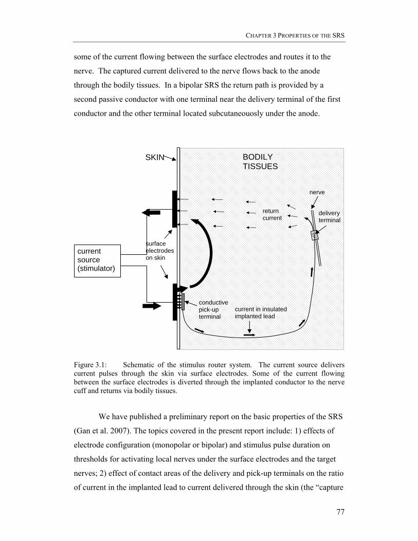
CHAPTER 3 PROPERTIES OF THE SRS
some of the current flowing between the surface electrodes and routes it to the
nerve. The captured current delivered to the nerve flows back to the anode
through the bodily tissues. In a bipolar SRS the return path is provided by a
second passive conductor with one terminal near the delivery terminal of the first
conductor and the other terminal located subcutaneouosly under the anode.
Figure 3.1: Schematic of the stimulus router system. The current source delivers current pulses through the skin via surface electrodes. Some of the current flowing between the surface electrodes is diverted through the implanted conductor to the nerve cuff and returns via bodily tissues.
We have published a preliminary report on the basic properties of the SRS
(Gan et al. 2007). The topics covered in the present report include: 1) effects of
electrode configuration (monopolar or bipolar) and stimulus pulse duration on
thresholds for activating local nerves under the surface electrodes and the target
nerves; 2) effect of contact areas of the delivery and pick-up terminals on the ratio
of current in the implanted lead to current delivered through the skin (the “capture
SKIN BODILY TISSUES
return current
delivery terminal
surface electrodes on skin
current source (stimulator)
conductive pick-up terminal
current in insulated implanted lead
nerve
77
CHAPTER 3 PROPERTIES OF THE SRS
ratio”); 3) effect on nerve activation thresholds of including backing insulation on
the pick-up terminal and the relative sizes of the skin electrode and the underlying
pick-up terminal; 4) capture ratio as an indicator of system efficiency; 5)
comparison of thresholds of different delivery terminal designs; 6) thresho
changes in chronically implanted SRS leads with two different delivery termi
geometries; 7) effect on thresholds of relative distance between anode and
delivery terminal and 8) encapsulation of the nerve cuffs and nerve damage
ld
nal
.
3.2 Methods
3.2.1 SRS designs
The basic components of the SRS, an external stimulator, surface
electrod ne form
leads
des
3.2.1.1 Stimulator and Surface electrodes
ologies, West Warwick, Rhode
Island) 0
es, implanted leads and nerve cuffs, have all been in existence in o
or another for at least four decades. The novel aspect of the SRS is the
combination of surface stimulation with one or more passive implanted
designed to capture as much of the current flowing between the surface electro
as possible. In our study, we used a conventional external electrical stimulator and
explored various types and sizes of surface electrode, pick-up terminal and
delivery terminal.
A Grass SD9 stimulator (Grass Techn
was used to deliver voltage-controlled pulses (300 µs pulse duration, 6
Hz) between pairs of surface electrodes attached to the skin. The electrodes were
placed about 80mm apart on the animal’s back, well away from the target nerve
and muscles in the hindlimb. The skin was closely shaved and cleaned with
alcohol before the electrodes were applied.
78
CHAPTER 3 PROPERTIES OF THE SRS
Depending on the experiment, two types of surface electrode were used.
The first was a Kendall Soft-E H59P self adhesive gel electrode (34 x 23 mm with
a 10 mm diameter central terminal; The Kendall Company, Mansfield,
Massachusetts). The second comprised a carbonized rubber electrode with a self-
adhesive conductive gel layer (Re-flex Tantone, Uni-patch, Wabasha, Minnesota)
cut into discs of four different sizes (specified in Results).
3.2.1.2 SRS lead
The pick-up terminals investigated comprised 0.56mm thick stainless steel
sheet cut into rectangles and discs of different sizes and 15mm long cylindrical
conductive terminals made by coiling lengths of deinsulated multistranded
stainless steel wires (AS 632, Cooner Wire Inc., Chatsworth, CA) around a
1.2mm diameter silicone tubing (“Peterson” type electrode), as specified in
Results. The stainless steel sheets were insulated on the muscle side with adhesive
silicone sealant (RTV 108, General Electric Company, Waterford, NY). In a
given trial a terminal was placed subcutaneously under the surface cathode
through a small incision about 10mm away. In cases where bipolar stimulation
was tested, a second lead was implanted so that its pick-up terminal was located
under the surface anode.
Depending on the experiment, either nerve cuffs or hook electrodes were
tested as the delivery terminals. Monopolar and bipolar nerve cuffs were made by
sewing 4mm de-insulated ends of stainless steel multistranded wire (AS 814 wire,
Cooner Wire Inc., Chatsworth, CA) into a 6mm long, longitudinally slit silastic
tube (3.4mm inner diameter, 4.7mm outside diameter, Dow Corning Corp., MI).
To investigate the effects of electrode geometries on activation thresholds, nerve
cuffs with single and multi-segment cylindrical electrode contacts were tested. As
in the case of the pick-up terminals, the cylindrical delivery terminals were made
by winding lengths of deinsulated AS 632 multistranded stainless steel wires
around a 1.2mm silicone tubing to the desired segment length (see Results).The
cylindrical delivery terminals were fixed with silicone adhesive inside 8mm long,
79
CHAPTER 3 PROPERTIES OF THE SRS
longitudinally slit silastic tubes (3.4mm inner diameter, 4.7mm outside diameter,
Dow Corning Corp., MI). In all acute experiments, the delivery terminal was
placed on the common peroneal (CP) nerve innervating the ankle dorsiflexor
muscles. In two chronic experiments, SRS leads were implanted on both the CP
and tibial nerves.
3.2.1.3 "Internal" versus "total" current and capture ratio
The current delivered through the surface electrodes ("total current", Itotal)
was measured indirectly in terms of the voltage across a 100 Ω resistor placed in
series with the negative output of the stimulator and the surface cathode. In acute
experiments only, the current in the implanted conductor ("internal" or "lead"
current, Ilead) was likewise measured in terms of the voltage across a 100 Ω
resistor placed in series with separate pick-up and delivery leads which were
brought out through the skin (this externalization of the leads was for test
purposes only and would not occur in clinical versions of SRS systems). The
proportion of the total current flowing through the implanted conductor, Ilead/Itotal,
was referred as the capture ratio (CR) of the SRS.
3.2.2 Amplifiers
Two Tektronix (ADA 400A, Tektronix Inc., Texas) differential amplifiers
and a Tektronix TDS 3014B oscilloscope (Tektronix Inc., Texas) were used to
measure the voltages referred to in 3.2.1.3.
3.2.3 Experimental procedures
All animal experiments were performed with the approval of the
University of Alberta Health Sciences Animal Policy and Welfare Committee.
Non-recovery experiments were performed in eight rabbits. The animals were
80
CHAPTER 3 PROPERTIES OF THE SRS
treated pre-operatively with intramuscular ketamine (10mg/Kg), acetylpromazine
(0.05mg/Kg) and glycopyrrolate (0.04mg/kg). A mixture of gaseous anesthetic
isoflurane (2-4%, Forane; Baxter Corp., Toronto, Ontario) in carbogen was used
to induce and maintain anesthesia. Respiration was monitored with a Beeper
animal respiration monitor (Spencer Instrumentation, Irvine, Ca) and pulse rate
was monitored with a SurgiVet V3404 pulse oximeter (SurgiVet, Waukesha, WI).
A feedback-controlled heating pad was used to maintain body temperature. Depth
of anesthesia was monitored periodically by checking respiratory rate, heart rate
and motor responses to strong pinches applied to the toes.
After deep anesthesia was achieved, the throat, back and hind legs were
closely shaved. A tracheotomy was performed and an endotracheal tube was
inserted to allow automatic control of ventilation with a Model A.D.S. 1000
veterinary anesthesia delivery system (Engler Eng. Corp., Fl.). An intravenous
catheter was inserted into the marginal ear vein for administration of drugs and
fluids when necessary.
One or two small skin incisions were made in the lower lumbar region
lateral to the midline of the back to allow subcutaneous placement of the pick-up
terminals. The terminals were slid under the skin, to rest about 10mm away from
the incisions. About 10mm of the CP nerve was exposed proximal to the knee and
dissected free of its surrounding tissue. A nerve cuff was placed snugly around the
nerve and sutured closed with 4/0 silk. The experiments typically lasted twelve
hours, after which the animal was euthanized with intravenous sodium
pentobarbital.
In two cats, four SRS leads were implanted chronically in each cat to
activate the bilateral CP and tibial nerves. The surgical procedures have been
described in detail elsewhere (Gan et al. 2007) and they are summarized here. The
surgery, which lasted about three hours, was performed under aseptic conditions.
The animal was pre-operatively treated with intramuscular acetylpromazine
(0.1mg/kg), hydromorphone (0.05mg/kg) and glycopyrrolate (0.01mg/kg).
Isoflurane anesthesia was induced via a mask and maintained via a pediatric
81
CHAPTER 3 PROPERTIES OF THE SRS
endotracheal tube. Respiration, heart rate and depth of anesthesia were monitored
as described above. The legs and back were closely shaved, cleaned with soap
and swabbed with iodine solution. About 10 mm of the bilateral CP and tibial
nerves were exposed proximal to the knee joints and at the popiteal fossae
respectively. The nerve cuffs were placed snugly around the target nerves and
muscle layers were sutured closed with 3/0 Vicryl absorbable sutures. Each pick-
up terminal and connecting lead was tunneled under the skin to a separate skin
incision at the back, over the mid-thoracic region. The pick-up terminals were
sutured to the underlying fascia with 4/0 silk suture and the skin incisions were
sutured with 3/0 prolene. Post-operative analgesia was provided with
subcutaneous Ketoprofen (Anafen, Merial Canada, Inc., Quebec City, Quebec)
and a Fentanyl patch (Duragesic 25, Janssen-Ortho, Inc., Toronto, Ontario). Post-
operative recovery took place in an intensive care unit. Ampicillin was
administered for two to four days after surgery, followed by Amoxil (50 mg
tablets, two/ per day) for six additional days.
3.2.4 Finite element method models
In an attempt to optimize the design of delivery terminals in activating
nerves, three dimensional (3D) numerical models of five different designs of
delivery terminal were implemented using the finite element (FEM) method. The
3D models were constructed and partitioned into mesh elements using a finite
element software package (Comsol Multiphysics, Comsol Inc.). By way of
example, Figure 3.2 shows the geometry of a 3-contact nerve cuff electrode
model. In this case the electrode included three 1mm long conductive contacts
separated by 1.5mm of insulated material and encased in a non-conductive
(silicone) cuff that also enveloped the nerve (not shown). The tissue in which the
electrode was embedded was modeled as a cylindrical, homogeneous and
isotropic volume conductor with a diameter of 6cm and length of 20cm. The
conductive contacts of the delivery terminals were assumed to be electrically
connected and set to deliver -10 V with respect to an anode (a circular surface
82
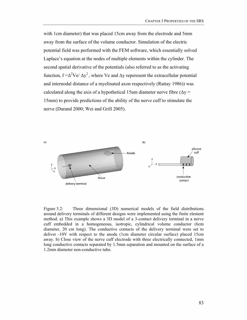
CHAPTER 3 PROPERTIES OF THE SRS
with 1cm diameter) that was placed 15cm away from the electrode and 5mm
away from the surface of the volume conductor. Simulation of the electric
potential field was performed with the FEM software, which essentially solved
Laplace’s equation at the nodes of multiple elements within the cylinder. The
second spatial derivative of the potentials (also referred to as the activating
function, f =∆2Ve/ ∆y2 , where Ve and ∆y reperesent the extracellular potential
and internodal distance of a myelinated axon respectively (Rattay 1986)) was
calculated along the axis of a hypothetical 15um diameter nerve fibre (∆y =
15mm) to provide predictions of the ability of the nerve cuff to stimulate the
nerve (Durand 2000; Wei and Grill 2005).
Figure 3.2: Three dimensional (3D) numerical models of the field distributions around delivery terminals of different designs were implemented using the finite element method. a) This example shows a 3D model of a 3-contact delivery terminal in a nerve cuff embedded in a homogeneous, isotropic, cylindrical volume conductor (6cm diameter, 20 cm long). The conductive contacts of the delivery terminal were set to deliver -10V with respect to the anode (1cm diameter circular surface) placed 15cm away. b) Close view of the nerve cuff electrode with three electrically connected, 1mm long conductive contacts separated by 1.5mm separation and mounted on the surface of a 1.2mm diameter non-conductive tube.
83
CHAPTER 3 PROPERTIES OF THE SRS
3.3 Results
3.3.1 Effects of electrode configurations and stimulation pulse duration on thresholds for activating local nerves under the surface electrodes and the target (distant) nerves
Ideally a NP based on the SRS should activate only the targeted nerves
and muscles and should not co-activate local, non- targeted nerves and muscles
under the surface electrodes (it should be understood in the following that the
term “muscle stimulation” refers to activation of muscles via the nerves that
innervate them. The electrical threshold for activating muscle fibres directly is
two orders of magnitude greater than that of activating nerves). To avoid such co-
activation, the surface current (Itotal) needed to elicit target muscle contractions via
the SRS lead should be lower than the current that excite nerves that activate local
muscles. It is well known that the stimulus pulse amplitude that activates a nerve
depends on the stimulus pulse duration. We wondered whether the
amplitude/duration relationship might differ for local and target muscle
activations evoked by the SRS. If so, this could potentially be exploited to
maximize the separation of thresholds of target and local contractions.
We explored this with monopolar and bipolar stimulation in four acute
rabbit experiments. Figure 3.3 shows the surface current thresholds, Itotal, at five
stimulus pulse durations: 20, 50, 100, 200 and 300µs. Two Kendall H59P surface
electrodes were placed 8cm apart on the back of the rabbit on closely shaved skin.
For monopolar stimulation, a single lead was implanted with its pick-up terminal
comprising a 1.77cm2 stainless steel disc placed subcutaneously under the cathode
and its delivery terminal inside a cuff attached to the common peroneal nerve, as
described in Methods. For bipolar stimulation, a second lead was used, with a
3.14cm2 stainless steel disc terminal placed under the anode and its delivery
terminal also in the cuff, 3mm away from the cathodal delivery terminal.
Thresholds were determined by close visual detection of minimal muscle
twitches. The threshold currents needed to activate the target muscles (ankle
84
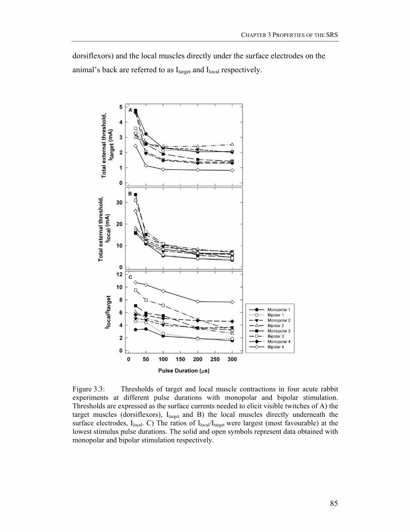
CHAPTER 3 PROPERTIES OF THE SRS
dorsiflexors) and the local muscles directly under the surface electrodes on the
animal’s back are referred to as Itarget and Ilocal respectively.
Figure 3.3: Thresholds of target and local muscle contractions in four acute rabbit experiments at different pulse durations with monopolar and bipolar stimulation. Thresholds are expressed as the surface currents needed to elicit visible twitches of A) the target muscles (dorsiflexors), Itarget and B) the local muscles directly underneath the surface electrodes, Ilocal. C) The ratios of Ilocal/Itarget were largest (most favourable) at the lowest stimulus pulse durations. The solid and open symbols represent data obtained with monopolar and bipolar stimulation respectively.
85
CHAPTER 3 PROPERTIES OF THE SRS
As anticipated, the current thresholds decreased as the stimulus pulse
duration increased. Figures 3.3A and B show that in most cases, bipolar
stimulation had lower Itarget and higher Ilocal values than monopolar stimulation.
These differences were associated with higher capture ratios for bipolar
stimulation (CRmonopolar = 0.09 + 0.04, CRbipolar = 0.14 + 0.06). In other words for
a given external current, more internal current was routed to the target nerve when
a second lead with a pick-up terminal under the surface anode was used. The
relative changes in Ilocal and Itarget as stimulus pulse duration increased were
expressed as ratios of Ilocal/Itarget in Figure 3.3C. Higher ratios indicate larger
differences between Itarget and Ilocal and are therefore more desirable. As expected,
the ratios were on average higher with bipolar stimulation. With both monopolar
and bipolar stimulation, the ratios were highest at the shortest stimulus pulse
durations. The lowest ratio in the four animals was 1.8, for monopolar
stimulation with 300µs stimulus pulse durations. Coincidently, the Itotal needed to
achieve maximal target muscle contraction through the SRS in chronically
implanted cats was 1.8 times motor threshold (Gan et al. 2007). The results
therefore suggest that maximal muscle contractions can be achieved before any
local muscles are recruited with both monopolar and bipolar stimulation even at
the longest pulse duration tested.
3.3.2 Effect of contact areas of the delivery and pick-up terminals on the ratio of current in the implanted lead to current delivered through the skin (“capture ratio”)
Since the surface areas of both the pick-up and delivery terminal affect the
electrode-tissue interface impedance of the implanted conductor, it was to be
expected that the capture ratio would be maximized by enlarging both terminals.
While larger terminals would have lower impedances, smaller terminals could be
accommodated in smaller nerve cuffs and so would be less invasive and
presumably cause less tissue inflammatory response. We investigated the
relationship between the implanted terminal surface areas and capture ratios in
86
CHAPTER 3 PROPERTIES OF THE SRS
two acute rabbit experiments. Ten different surface areas were tested for each
terminal. Figure 3.4A shows the mean capture ratios obtained in the two
experiments.
To avoid inaccuracy due to repeated placements of the electrodes, two
rectangular stainless steel electrodes provided with backing insulation and sliding
insulating sleeves were tested as pick-up and delivery terminals. Two skin
incisions were made on the back of the rabbit, about 10cm apart. The pick-up and
delivery terminals were slid under the skin through these incisions, to rest
subcutaneously about 2cm from the incision margins, with the conductive side of
the pick-up terminal facing the skin and the conductive side of the delivery
terminal facing muscle fascia (in this experiment we were only interested in the
flow of current between the implanted lead and subcutaneous tissue, so the
delivery terminal was not placed over a target nerve). The sliding sleeves
extended through the skin incisions and allowed for adjustments of the conductive
surface areas without moving the implanted electrodes. The cathode was placed
on the skin surface over the implanted pick-up terminal while the anode was
placed about 8cm away from the implanted delivery terminal, to mimic
monopolar stimulation.
Figure 3.4A shows that as expected, the capture ratios increased when the
terminal surface areas were increased. The capture ratios were more sensitive to
the area of the pick-up terminal (Ap) than the area of the delivery terminal (Ad),
possibly due to electrical impedance differences at the skin-electrode and
subcutaneous tissue-electrode interfaces. For both terminals, the capture ratio
increased substantially when the surface areas increased from 0.1cm2 to 1cm2 and
reached a plateau for surface areas larger than 1cm2. The regression surface fitted
to the data (r2=0.90) in Figure 3.4B showed that with an optimal pick-up terminal
size of 1.0cm2 , the capture ratio increased by more than 50% (0.19 to 0.31) as
the delivery terminal surface areas increased from 0.1cm2 to 1.0cm2.
87
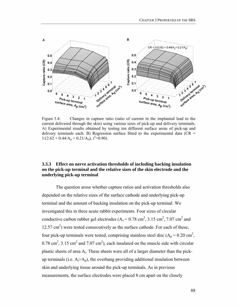
CHAPTER 3 PROPERTIES OF THE SRS
Figure 3.4: Changes in capture ratio (ratio of current in the implanted lead to the current delivered through the skin) using various sizes of pick-up and delivery terminals. A) Experimental results obtained by testing ten different surface areas of pick-up and delivery terminals each. B) Regression surface fitted to the experimental data (CR = 1/(2.62 + 0.44/Ap + 0.21/Ad), r2=0.90).
3.3.3 Effect on nerve activation thresholds of including backing insulation on the pick-up terminal and the relative sizes of the skin electrode and the underlying pick-up terminal
The question arose whether capture ratios and activation thresholds also
depended on the relative sizes of the surface cathode and underlying pick-up
terminal and the amount of backing insulation on the pick-up terminal. We
investigated this in three acute rabbit experiments. Four sizes of circular
conductive carbon rubber gel electrodes (As = 0.78 cm2, 3.15 cm2, 7.07 cm2 and
12.57 cm2) were tested consecutively as the surface cathode. For each of these,
four pick-up terminals were tested, comprising stainless steel disc (Ap = 0.20 cm2,
0.78 cm2, 3.15 cm2 and 7.07 cm2), each insulated on the muscle side with circular
plastic sheets of area Ai. These sheets were all of a larger diameter than the pick-
up terminals (i.e. Ai>Ap), the overhang providing additional insulation between
skin and underlying tissue around the pick-up terminals. As in previous
measurements, the surface electrodes were placed 8 cm apart on the closely
88
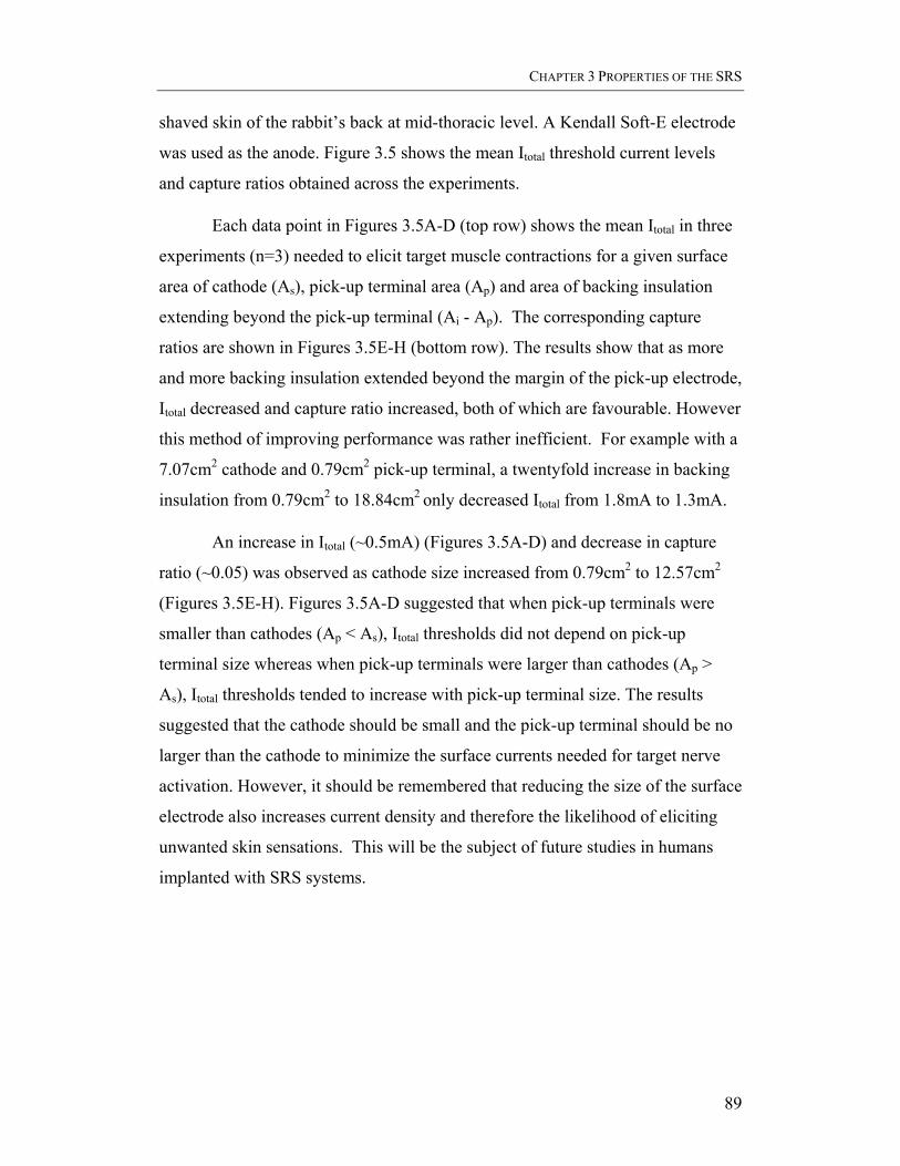
CHAPTER 3 PROPERTIES OF THE SRS
shaved skin of the rabbit’s back at mid-thoracic level. A Kendall Soft-E electrode
was used as the anode. Figure 3.5 shows the mean Itotal threshold current levels
and capture ratios obtained across the experiments.
Each data point in Figures 3.5A-D (top row) shows the mean Itotal in three
experiments (n=3) needed to elicit target muscle contractions for a given surface
area of cathode (As), pick-up terminal area (Ap) and area of backing insulation
extending beyond the pick-up terminal (Ai - Ap). The corresponding capture
ratios are shown in Figures 3.5E-H (bottom row). The results show that as more
and more backing insulation extended beyond the margin of the pick-up electrode,
Itotal decreased and capture ratio increased, both of which are favourable. However
this method of improving performance was rather inefficient. For example with a
7.07cm2 cathode and 0.79cm2 pick-up terminal, a twentyfold increase in backing
insulation from 0.79cm2 to 18.84cm2 only decreased Itotal from 1.8mA to 1.3mA.
An increase in Itotal (~0.5mA) (Figures 3.5A-D) and decrease in capture
ratio (~0.05) was observed as cathode size increased from 0.79cm2 to 12.57cm2
(Figures 3.5E-H). Figures 3.5A-D suggested that when pick-up terminals were
smaller than cathodes (Ap < As), Itotal thresholds did not depend on pick-up
terminal size whereas when pick-up terminals were larger than cathodes (Ap >
As), Itotal thresholds tended to increase with pick-up terminal size. The results
suggested that the cathode should be small and the pick-up terminal should be no
larger than the cathode to minimize the surface currents needed for target nerve
activation. However, it should be remembered that reducing the size of the surface
electrode also increases current density and therefore the likelihood of eliciting
unwanted skin sensations. This will be the subject of future studies in humans
implanted with SRS systems.
89
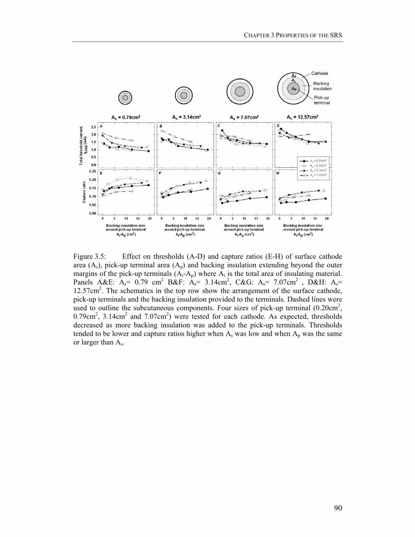
CHAPTER 3 PROPERTIES OF THE SRS
Figure 3.5: Effect on thresholds (A-D) and capture ratios (E-H) of surface cathode area (As), pick-up terminal area (Ap) and backing insulation extending beyond the outer margins of the pick-up terminals (Ai-Ap) where Ai is the total area of insulating material. Panels A&E: As= 0.79 cm2 B&F: As= 3.14cm2, C&G: As= 7.07cm2 , D&H: As= 12.57cm2. The schematics in the top row show the arrangement of the surface cathode, pick-up terminals and the backing insulation provided to the terminals. Dashed lines were used to outline the subcutaneous components. Four sizes of pick-up terminal (0.20cm2, 0.79cm2, 3.14cm2 and 7.07cm2) were tested for each cathode. As expected, thresholds decreased as more backing insulation was added to the pick-up terminals. Thresholds tended to be lower and capture ratios higher when As was low and when Ap was the same or larger than As.
90
CHAPTER 3 PROPERTIES OF THE SRS
3.3.4 Capture ratio as an indicator of system efficiency
In three acute rabbit experiments, we used monopolar hook electrodes of
seven different widths to serve as delivery terminals, the nerve being dissected
free from surrounding tissues and surrounded either by isotonic saline or paraffin
oil. Paraffin oil is a biologically inert medium with a much higher electrical
impedance than isotonic saline. This method allowed us to compare the external
current thresholds in the presence and absence of the shunting effect of
extracellular saline surrounding the nerve. A pair of Kendall Soft-E electrodes
was placed on the back of the rabbit as surface electrodes. The pick-up terminal in
this set of measurements was a 1.80cm2 stainless steel disc. About 10 mm of the
CP nerve was exposed proximal to the knee. The animal was mounted in a
stereotaxic frame. Elastic bands were clipped to the skin around the incision and
attached to surrounding fixation points on the frame, elevating the skin to form a
small pool which could be filled either with isotonic saline or paraffin oil warmed
to body temperature.
Figure 3.6 shows the Itotal thresholds and capture ratios with the saline and
paraffin media. As expected from Figure 3.4, Itotal threshold decreased and capture
ratio increased slightly as the hook electrode size increased. However, when
saline was the medium, despite about a four-fold increase in capture ratios, Itotal
more than doubled. This showed that although the capture ratio is an important
measure, it is not the only determinant of the efficiency of an SRS. Low
thresholds can be achieved even when the capture ratio is low if the delivery
terminal is in good contact with the target nerve and the current it delivers is
directed into and along the nerve rather than escaping ineffectively into the
adjacent tissues. This can be achieved for example by enclosing the nerve and
delivery terminal in a non-conductive nerve cuff. An optimized SRS would have
a high capture ratio, close contact with the nerve and minimal ineffective current.
91
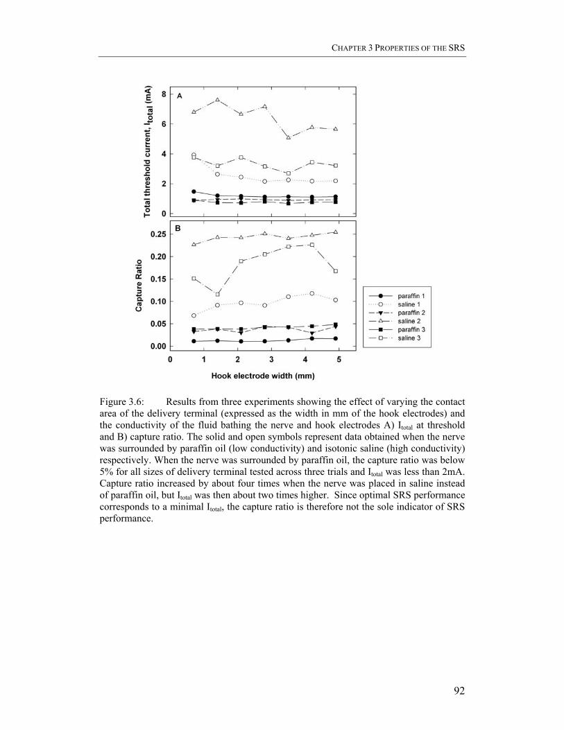
CHAPTER 3 PROPERTIES OF THE SRS
Figure 3.6: Results from three experiments showing the effect of varying the contact area of the delivery terminal (expressed as the width in mm of the hook electrodes) and the conductivity of the fluid bathing the nerve and hook electrodes A) Itotal at threshold and B) capture ratio. The solid and open symbols represent data obtained when the nerve was surrounded by paraffin oil (low conductivity) and isotonic saline (high conductivity) respectively. When the nerve was surrounded by paraffin oil, the capture ratio was below 5% for all sizes of delivery terminal tested across three trials and Itotal was less than 2mA. Capture ratio increased by about four times when the nerve was placed in saline instead of paraffin oil, but Itotal was then about two times higher. Since optimal SRS performance corresponds to a minimal Itotal, the capture ratio is therefore not the sole indicator of SRS performance.
92
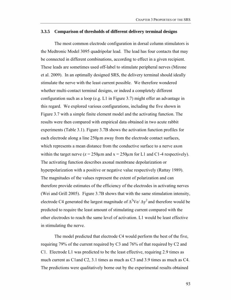
CHAPTER 3 PROPERTIES OF THE SRS
3.3.5 Comparison of thresholds of different delivery terminal designs
The most common electrode configuration in dorsal column stimulators is
the Medtronic Model 3095 quadripolar lead. The lead has four contacts that may
be connected in different combinations, according to effect in a given recipient.
These leads are sometimes used off-label to stimulate peripheral nerves (Mirone
et al. 2009). In an optimally designed SRS, the delivery terminal should ideally
stimulate the nerve with the least current possible. We therefore wondered
whether multi-contact terminal designs, or indeed a completely different
configuration such as a loop (e.g. L1 in Figure 3.7) might offer an advantage in
this regard. We explored various configurations, including the five shown in
Figure 3.7 with a simple finite element model and the activating function. The
results were then compared with empirical data obtained in two acute rabbit
experiments (Table 3.1). Figure 3.7B shows the activation function profiles for
each electrode along a line 250µm away from the electrode contact surfaces,
which represents a mean distance from the conductive surface to a nerve axon
within the target nerve (z = 250µm and x = 250µm for L1 and C1-4 respectively).
The activating function describes axonal membrane depolarization or
hyperpolarization with a positive or negative value respectively (Rattay 1989).
The magnitudes of the values represent the extent of polarization and can
therefore provide estimates of the efficiency of the electrodes in activating nerves
(Wei and Grill 2005). Figure 3.7B shows that with the same stimulation intensity,
electrode C4 generated the largest magnitude of ∆2Ve/ ∆y2 and therefore would be
predicted to require the least amount of stimulating current compared with the
other electrodes to reach the same level of activation. L1 would be least effective
in stimulating the nerve.
The model predicted that electrode C4 would perform the best of the five,
requiring 79% of the current required by C3 and 76% of that required by C2 and
C1. Electrode L1 was predicted to be the least effective, requiring 2.9 times as
much current as C1and C2, 3.1 times as much as C3 and 3.9 times as much as C4.
The predictions were qualitatively borne out by the experimental results obtained
93
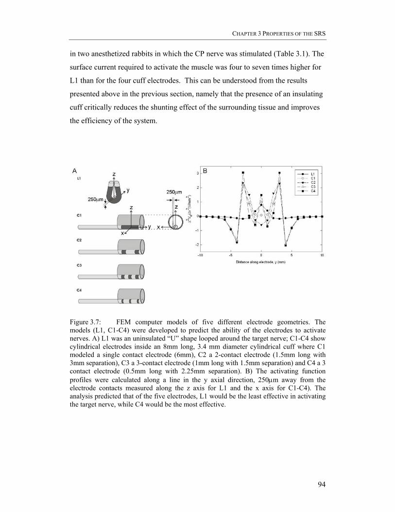
CHAPTER 3 PROPERTIES OF THE SRS
in two anesthetized rabbits in which the CP nerve was stimulated (Table 3.1). The
surface current required to activate the muscle was four to seven times higher for
L1 than for the four cuff electrodes. This can be understood from the results
presented above in the previous section, namely that the presence of an insulating
cuff critically reduces the shunting effect of the surrounding tissue and improves
the efficiency of the system.
Figure 3.7: FEM computer models of five different electrode geometries. The models (L1, C1-C4) were developed to predict the ability of the electrodes to activate nerves. A) L1 was an uninsulated “U” shape looped around the target nerve; C1-C4 show cylindrical electrodes inside an 8mm long, 3.4 mm diameter cylindrical cuff where C1 modeled a single contact electrode (6mm), C2 a 2-contact electrode (1.5mm long with 3mm separation), C3 a 3-contact electrode (1mm long with 1.5mm separation) and C4 a 3 contact electrode (0.5mm long with 2.25mm separation). B) The activating function profiles were calculated along a line in the y axial direction, 250µm away from the electrode contacts measured along the z axis for L1 and the x axis for C1-C4). The analysis predicted that of the five electrodes, L1 would be the least effective in activating the target nerve, while C4 would be the most effective.
94
CHAPTER 3 PROPERTIES OF THE SRS
Experiment #1 Experiment #2
Electrode
Maximal ∆2Ve/∆x2 (V/mm2)
Itotal (mA)
Ilead (mA)
Capture ratio
Itotal (mA)
Ilead (mA)
Capture ratio
L1 0.79 5.03 0.87 0.17 2.80 0.47 0.17 C1 2.33 0.88 0.09 0.10 0.56 0.08 0.15 C2 2.33 0.83 0.07 0.08 0.60 0.05 0.09 C3 2.42 1.00 0.07 0.07 0.70 0.06 0.08 C4 3.06 0.70 0.05 0.07 0.69 0.07 0.09
Table 3.1: Comparison of the maximal activation function values shown in Figure 3.7B and the threshold surface current (Itotal), the corresponding current in the implanted lead (Ilead), and the capture ratio (Ilead/ Itotal) obtained in two acute rabbit experiments. In the experimental data, Itotal and Ilead were higher with electrode L1 than with electrodes C1-C4 and this agrees with the activating function prediction. There were smaller, variable differences between electrodes C1, C2, C3 and C4 in the experimental data that were not well correlated with the modeled predictions. Thus the activating function predicted the performance of electrodes of very different geometries but was less successful in the case of the cuff electrodes C1-C4, where factors such as alignment between the nerve and the electrodes or presence of variable thicknesses of connective tissue might be very influential in determining threshold levels.
There were no systematic differences between C1, C2, C3 and C4 in the
experimentally measured values of Itotal. When individual electrode contacts in
electrodes C2-4 were tested experimentally (data not shown), the thresholds were
found to vary considerably between them, depending on the alignment of the
nerve and the cuff and other unknown factors. This suggests that in practice,
factors which cannot easily be measured or accounted for in finite element models
may play a significant role in determining performance.
3.3.6 Threshold changes in chronically implanted SRS leads with two different delivery terminal geometries
In has been shown that in chronically implanted electrodes, threshold
levels can vary over time due to inflammatory responses and growth of
connective tissue in and around the implants (Gan et al. 2007; Grill and Mortimer
1998; 1995). The amount of tissue growth is likely to depend on electrode
geometries and this in turn could differentially affect threshold levels over the
95
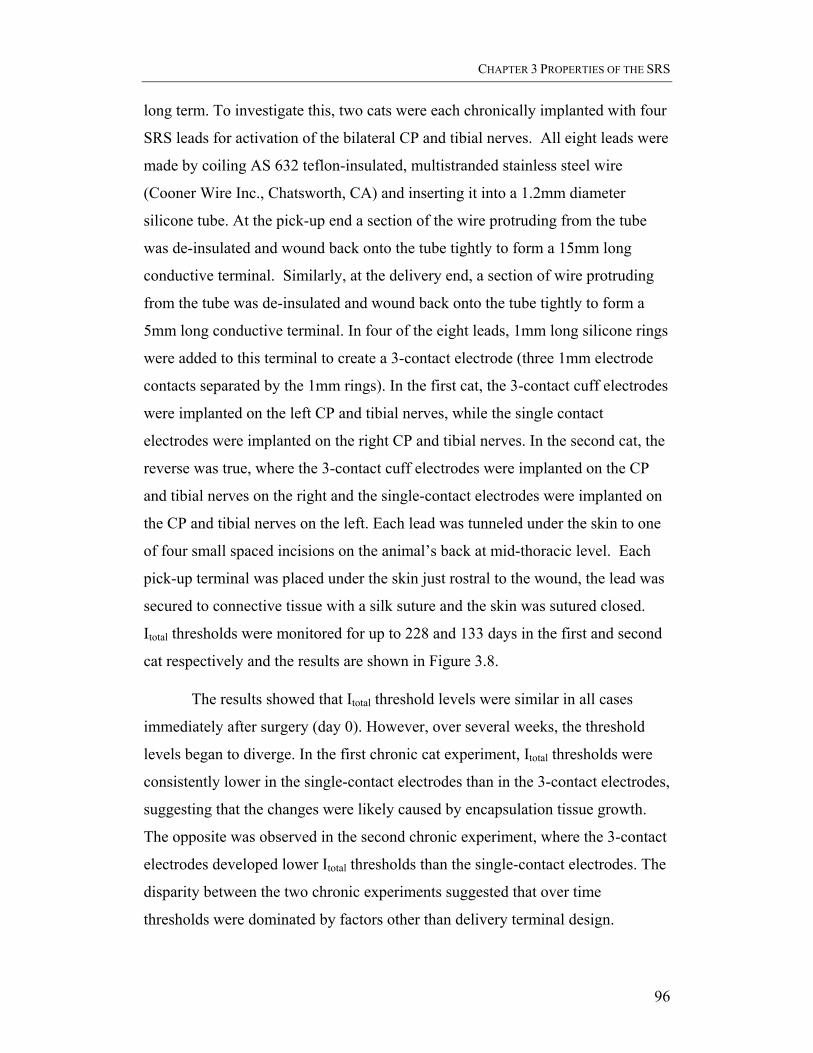
CHAPTER 3 PROPERTIES OF THE SRS
long term. To investigate this, two cats were each chronically implanted with four
SRS leads for activation of the bilateral CP and tibial nerves. All eight leads were
made by coiling AS 632 teflon-insulated, multistranded stainless steel wire
(Cooner Wire Inc., Chatsworth, CA) and inserting it into a 1.2mm diameter
silicone tube. At the pick-up end a section of the wire protruding from the tube
was de-insulated and wound back onto the tube tightly to form a 15mm long
conductive terminal. Similarly, at the delivery end, a section of wire protruding
from the tube was de-insulated and wound back onto the tube tightly to form a
5mm long conductive terminal. In four of the eight leads, 1mm long silicone rings
were added to this terminal to create a 3-contact electrode (three 1mm electrode
contacts separated by the 1mm rings). In the first cat, the 3-contact cuff electrodes
were implanted on the left CP and tibial nerves, while the single contact
electrodes were implanted on the right CP and tibial nerves. In the second cat, the
reverse was true, where the 3-contact cuff electrodes were implanted on the CP
and tibial nerves on the right and the single-contact electrodes were implanted on
the CP and tibial nerves on the left. Each lead was tunneled under the skin to one
of four small spaced incisions on the animal’s back at mid-thoracic level. Each
pick-up terminal was placed under the skin just rostral to the wound, the lead was
secured to connective tissue with a silk suture and the skin was sutured closed.
Itotal thresholds were monitored for up to 228 and 133 days in the first and second
cat respectively and the results are shown in Figure 3.8.
The results showed that Itotal threshold levels were similar in all cases
immediately after surgery (day 0). However, over several weeks, the threshold
levels began to diverge. In the first chronic cat experiment, Itotal thresholds were
consistently lower in the single-contact electrodes than in the 3-contact electrodes,
suggesting that the changes were likely caused by encapsulation tissue growth.
The opposite was observed in the second chronic experiment, where the 3-contact
electrodes developed lower Itotal thresholds than the single-contact electrodes. The
disparity between the two chronic experiments suggested that over time
thresholds were dominated by factors other than delivery terminal design.
96
CHAPTER 3 PROPERTIES OF THE SRS
Figure 3.8: Itotal changes in two cats which were each chronically implanted with four SRS leads for activation of tibial and CP nerves bilaterally. In each cat, the tibial and CP nerves on one side were implanted with 3-contact electrodes (type C3 in Figure 3.7). The contralateral tibial and CP nerves were implanted with 5mm long, single-contact nerve cuff electrodes type C1 in Figure 3.7). The corresponding pick-up terminals were 15mm long “Peterson” type electrodes that were placed subcutaneously in lumbar locations.
3.3.7 Effect on thresholds of relative distance between anode and delivery terminal
In all our previous experiments, the anodes were intentionally placed at a
distance away from the target nerves to minimize the effect of surface current
flow in that area on threshold levels. It is expected that in some clinical
applications, more current can be directed to the target tissues to achieve lower
activation thresholds by placing the anode closer to the delivery terminal. In the
first chronically implanted cat described in 3.3.6, we investigated the changes in
Itotal thresholds in relation to relative distance between the anode and the delivery
terminal in two SRS leads implanted on the tibial nerves bilaterally and one SRS
97
CHAPTER 3 PROPERTIES OF THE SRS
lead implanted on the CP nerve. The positions of delivery terminals with respect
to the implanted nerve cuffs were determined by palpation. The surface cathode
was a Kendall Soft-E self-adhesive gel electrode (34 x 23 mm rectangle with a
10mm diameter disc of carbon located in its centre) and was placed overlying the
pick-up terminal. The anodal surface electrode was a custom made, wettable cloth
electrode of 3 cm diameter made by sewing diaper material onto a 3cm diameter
terminal consisting of stainless steel mesh. The results are shown in Figure 3.9.
The results show that thresholds were lowest when the anode was placed
on the skin directly over the delivery terminal (dad = 0). Away from this position,
Itotal gradually increased when anode was moved towards the cathode and was
highest when the anode was placed just beyond the cathode, at dad = 18cm and
20cm for the tibial and CP implants respectively. Itotal begin to decrease as dad
further increased, with the anode moved further away from both the cathode and
delivery terminal. It was observed that at equidistance from the cathode, Itotal was
lower when the anode was placed closer to the delivery terminal. The results
suggested that both anode-delivery terminal and anode-cathode distances affect
Itotal thresholds. This could be explained by the relative changes in surface anode-
cathode impedance and anode-delivery terminal impedance when the anode was
placed at different distances relative to the cathode and delivery terminals. It is
evident that the capture ratio depends on the relative impedance of two current
paths: 1) surface cathode through the skin and subcutaneous tissue to the pick-up
terminal interface, then through the lead to the delivery terminal interface and
back through the tissue and skin to the anode; 2) through the skin and
subcutaneous tissues between the surface electrodes. The lower the impedance of
current path 1 and the higher that of current path 2, the larger the share of current
through the implanted conductor (the higher the capture ratio and the lower the
value of Itotal). In Figure 3.9, at dad = 0, the impedance of current path 1 was
presumably minimal because the anode was closest to the delivery terminal,
whereas that of current path 2 had increased with the increased spacing of the
surface electrodes. This resulted in the lowest Itotal threshold. The closer the anode
98
CHAPTER 3 PROPERTIES OF THE SRS
to the cathode, the lower was the impedance of current path 2 and the higher that
of current path 1, hence the larger was Itotal.
3.3.8 Encapsulation of the nerve cuffs and nerve damage
In post-mortem dissections, connective tissue in-growth was noted within
and around the implanted nerve cuffs in the two chronically implanted animals.
The subcutaneous pick-up electrodes also tended to be encapsulated with a layer
of connective tissue up to about 1mm thick. This was not associated with an
increase in thresholds over time, so we assume that the connective tissue did not
significantly separate the delivery terminals from the nerves, nor did it
significantly increase the tissue-metal interface impedances. No tissue erosion
has been noted on visual inspection, though histology would be required to detect
changes in the implanted nerves.
99
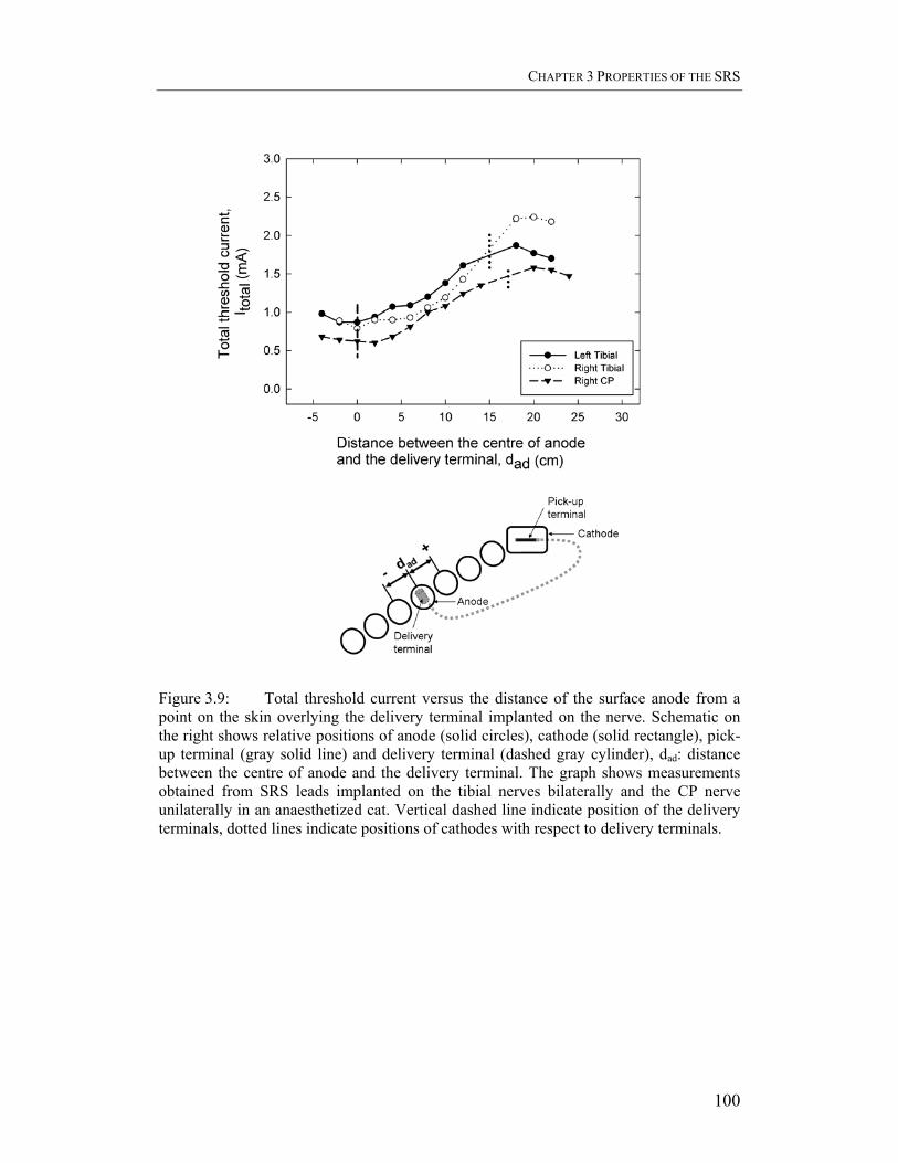
CHAPTER 3 PROPERTIES OF THE SRS
Figure 3.9: Total threshold current versus the distance of the surface anode from a point on the skin overlying the delivery terminal implanted on the nerve. Schematic on the right shows relative positions of anode (solid circles), cathode (solid rectangle), pick-up terminal (gray solid line) and delivery terminal (dashed gray cylinder), dad: distance between the centre of anode and the delivery terminal. The graph shows measurements obtained from SRS leads implanted on the tibial nerves bilaterally and the CP nerve unilaterally in an anaesthetized cat. Vertical dashed line indicate position of the delivery terminals, dotted lines indicate positions of cathodes with respect to delivery terminals.
100
CHAPTER 3 PROPERTIES OF THE SRS
3.4 Discussion
The aim of this study was to further investigate the characteristics of the
SRS and to optimize its components and stimulation parameters so as to
maximize its performance in activating target nerves and muscles. We found that
shorter stimulus pulse durations increased the safety margin between the
activation of target and local muscles. This effect of stimulus pulse duration can
be explained by results obtained in passive cable model studies (Grill and
Mortimer 1996), where stimulus currents with short pulse durations were shown
to increase threshold differences between nerve fibres located at different
distances from the stimulating electrode.
As we only compared thresholds of local and target muscle recruitment in
this study, the question could be asked, what about activation of cutaneous and
subdermal nociceptors? If muscle contractions elicited through an SRS caused
pain under the surface electrodes, it would not be a viable system. This issue was
addressed indirectly in our previous study (Gan et al. 2007) by comparing the
surface currents required to elicit muscle contractions in the animal experiments
to sensory thresholds in humans. In most cases the motor thresholds were much
lower than the sensory thresholds. In January 2008 we were able to make a more
direct comparison in a person undergoing a nerve graft operation. The threshold
of target muscle contractions elicited intra-operatively by surface stimulation
through a temporary SRS implant was 45% of the sensory threshold via the same
surface electrodes prior to surgery (Prochazka et al. 2008). Finally, in an SRS
implanted in a tetraplegic person in June 2008 (Gan et al. 2009), strong hand
grasp and release is routinely achieved in the absence of any skin sensation. A
full report of these human results is in preparation.
Bipolar stimulation reduced the amount of surface current needed to
activate the target muscles by increasing the capture ratios. However this would
require twice as many leads to be routed under the skin during surgery, so the
costs would generally outweigh the benefits. With monopolar stimulation,
101
CHAPTER 3 PROPERTIES OF THE SRS
depending on the location of the target nerve, the amount of surface current
needed to activate the target muscles was reduced by placing the anode on the
skin closer to the underlying delivery terminal on the nerve.
As expected, capture ratios increased with larger pick-up and delivery
terminals. Decreases in Itotal and increases in capture ratios were also observed
with smaller skin electrodes, larger pick-up terminals and backing insulation that
overlapped the pick-up terminals. However, it is important to note that in this
study we found that the capture ratio was not the only factor to be taken into
account when predicting the amount of surface current needed to activate target
muscles. This was not clear from our first study (Gan et al. 2007), but it was a
welcome finding as it showed that low external current thresholds could be
achieved even when the capture ratio was low provided that the delivery terminal
was in good contact with the target nerve and there was little shunting of current
away from the nerve by the surrounding media. Not surprisingly, these criteria
are both met in well-designed nerve cuff electrodes. This is clearly shown in
3.3.5, in which the presence of an insulating silicone nerve cuff greatly reduced
the surface current needed to activate the target nerve.
Though the predictions of performance derived from finite element
modeling agreed reasonably well with the experimental data described in this
report, it also became apparent that in the long-term implants, other factors were
at play, that caused changes in electrode performance. These could include
alterations in impedance at the electrode-tissue interface, re-alignment of the cuff
and nerve and the growth of connective tissue. Connective tissue that develops
around implants consists mostly of tightly packed layers of fibroblast and
collagen, which tend to have a higher impedance than normal tissue (Grill and
Mortimer 1994). This would reduce the electric field along the target nerve,
increasing Itotal thresholds. On the other hand, a connective tissue capsule formed
around the nerve cuff would tend to reduce current shunting to the surrounding
non-targeted tissues, thereby reducing Itotal thresholds. It will be interesting to
explore these factors in future SRS implants.
102
CHAPTER 3 PROPERTIES OF THE SRS
Regarding the clinical application of the SRS, for example as a motor NP,
external electrodes will always be required and this raises the question of the
convenience and reproducibility of donning and doffing such electrodes. There
are basically two options: 1) the surface electrodes, which may be attached to the
inside of a cuff or garment, are donned and doffed daily; 2) the use of gel
electrodes that can stay on the skin for one or more weeks. The first option is
familiar from current surface stimulators, and has been implemented successfully
in the pilot human study (Gan et al. 2009). The effect on SRS thresholds of
surface electrode placement (Figure 3.9) has also been confirmed in the human
study. Basically, the smaller the surface electrode the more sensitive is the system
to incorrect placement. However the recipient in the pilot study has had no
difficulty coping with this variability. This will be discussed in detail in the
forthcoming report. Regarding multi-week electrodes, provided hypo-allergenic
gel is used, this could be a viable and convenient option, particularly as their
individual placement could be optimized, but this approach requires further study.
Finally, the question arises as to how many SRS leads could be implanted
and independently controlled. This was partly addressed in our previous
publication (Gan et al. 2007). The first human recipient has 3 implanted platinum-
iridium SRS leads independently operated through surface electrodes deployed
around the wrist within a band of skin about 4cm wide. A wristlet with internal
moistened pad electrodes and a built-in stimulator the size of a credit card is
donned and doffed in less than a minute. It is clear from this implant that several
more SRS leads could be implanted, bearing in mind that each additional lead
would require a surface electrode occupying a minimum of 7cm2 of skin surface
(20mm diameter electrodes, 15mm centre to centre).
In our first full paper on the SRS, proof-of-principle of the system as a NP
was demonstrated and its basic properties were explored. In this study, we
described in further detail the functional properties of the SRS, with the aim of
optimizing its performance. We believe that the technique and results we have
103

CHAPTER 3 PROPERTIES OF THE SRS
reported so far provided the basis for a new family of neural prostheses that will
serve as a cost-effective alternative to currently existing NP systems.
3.5 Acknowledgements
This work was supported by the Canadian Institutes of Health Research
and the Alberta Heritage Foundation for Medical Research. We thank the
members of the Health Sciences Animal Laboratory Services at the University of
Alberta for the diligent care of the animals involved in the study.
3.6 References
Breit S, Schulz JB, and Benabid AL. Deep brain stimulation. Cell Tissue Res 318: 275-288, 2004.
Brindley GS, Polkey CE, Rushton DN, and Cardozo L. Sacral anterior root stimulators for bladder control in paraplegia: the first 50 cases. J Neurol Neurosurg Psychiatry 49: 1104-1114, 1986.
Clark GM, Tong YC, Black R, Forster IC, Patrick JF, et al. A multiple electrode cochlear implant. J Laryngol Otol 91: 935-945, 1977.
Durand D. The biomedical engineering handbook. edited by Bronzino JDCRC Press, 2000.
Gan LS, Prochazka A, Bornes TD, Denington AA, and Chan KM. A new means of transcutaneous coupling for neural prostheses. IEEE Trans Biomed Eng 54: 509-517, 2007.
Gan LS, Prochazka A, Olson J, Morhart M, Ravid EN, et al. Preliminary results of the first permanent human implant of the stimulus router system, a novel neural prosthesis. . In: Society of Neuroscience. Chicago, IL: 2009.
Glenn WW, Holcomb WG, Shaw RK, Hogan JF, and Holschuh KR. Long-term ventilatory support by diaphragm pacing in quadriplegia. Ann Surg 183: 566-577, 1976.
104
CHAPTER 3 PROPERTIES OF THE SRS
Grill WM, Jr., and Mortimer JT. The effect of stimulus pulse duration on selectivity of neural stimulation. IEEE Trans Biomed Eng 43: 161-166, 1996.
Grill WM, and Mortimer JT. Electrical properties of implant encapsulation tissue. Ann Biomed Eng 22: 23-33, 1994.
Grill WM, and Mortimer JT. Stability of the input-output properties of chronically implanted multiple contact nerve cuff stimulating electrodes. IEEE Trans Rehabil Eng 6: 364-373, 1998.
Grill WM, and Mortimer JT. Temporal stability of nerve cuff electrode recruitment properties. In: IEEE 17th Annual Conference, Engineering in Medicine and Biology Society1995.
Horch KW, and Dhillon GS editors. Neuroprosthetics. Theory and Practice. River Edge, NJ: World Scientific, 2004.
Liberson WT, Holmquest HJ, Scot D, and Dow M. Functional electrotherapy: stimulation of the peroneal nerve synchronized with the swing phase of the gait of hemiplegic patients. Arch Phys Med Rehabil 42: 101-105, 1961.
Loeb GE, Peck RA, Moore WH, and Hood K. BION system for distributed neural prosthetic interfaces. Med Eng Phys 23: 9-18, 2001.
Mirone G, Natale M, and Rotondo M. Peripheral median nerve stimulation for the treatment of iatrogenic complex regional pain syndrome (CRPS) type II after carpal tunnel surgery. J Clin Neurosci 16: 825-827, 2009.
Peckham PH, and Knutson JS. Functional electrical stimulation for neuromuscular applications. Annu Rev Biomed Eng 7: 327-360, 2005.
Popovic MR, Popovic DB, and Keller T. Neuroprostheses for grasping. Neurol Res 24: 443-452, 2002.
Prochazka A, Gan LS, Olson J, and Mohart M. The stimulus router system (SRS): first human intra-operative testing of a novel neural prosthesis. In: Neural Interfaces Conference. Cleveland: 2008.
Rattay F. Analysis of models for external stimulation of axons. IEEE Trans Biomed Eng 33: 974-977, 1986.
Rattay F. Analysis of models for extracellular fiber stimulation. IEEE Trans Biomed Eng 36: 676-682, 1989.
105
CHAPTER 3 PROPERTIES OF THE SRS
Waltz JM. Spinal cord stimulation: a quarter century of development and investigation. A review of its development and effectiveness in 1,336 cases. Stereotact Funct Neurosurg 69: 288-299, 1997.
Wei XF, and Grill WM. Current density distributions, field distributions and impedance analysis of segmented deep brain stimulation electrodes. J Neural Eng 2: 139-147, 2005.
106
Chapter 4
First human intra-operative testing of the Stimulus Router System*
4.1 Introduction
The application of neural prostheses (NPs) for restoration of sensory or
motor functions after brain or spinal cord injury has produced a variety of system
designs catering to different clinical uses (Peckham and Knutson 2005). Surface
NPs deliver stimulus current pulses via surface electrodes placed on the skin using
external stimulators. While these devices are non-invasive and inexpensive, they
are often poorly selective, sensitive to electrode positions and can activate
cutaneous sensory nerves, causing pain or discomfort. With implantable NPs,
stimulators, leads and sensors can be enclosed in the body. Selectivity is improved
and complexity of daily donning is avoided in these systems, but costs are high
and might not be justified if clinical utility is limited or uncertain.
The stimulus router system (SRS) is a novel NP which combines the
selectivity and reproducibility of an implanted NP and the low cost of a surface
NP (Figure 4.1) (Gan et al. 2007). An external stimulator is used to deliver
electrical pulses through a pair of surface electrodes attached to the skin. An
implanted passive conductor with a “pick-up” terminal under the cathodal * A version of this chapter has been published. Prochazka et al., 2008. 13th Annual International FES Society Conference. Freiburg, Germany: P4.14.
107
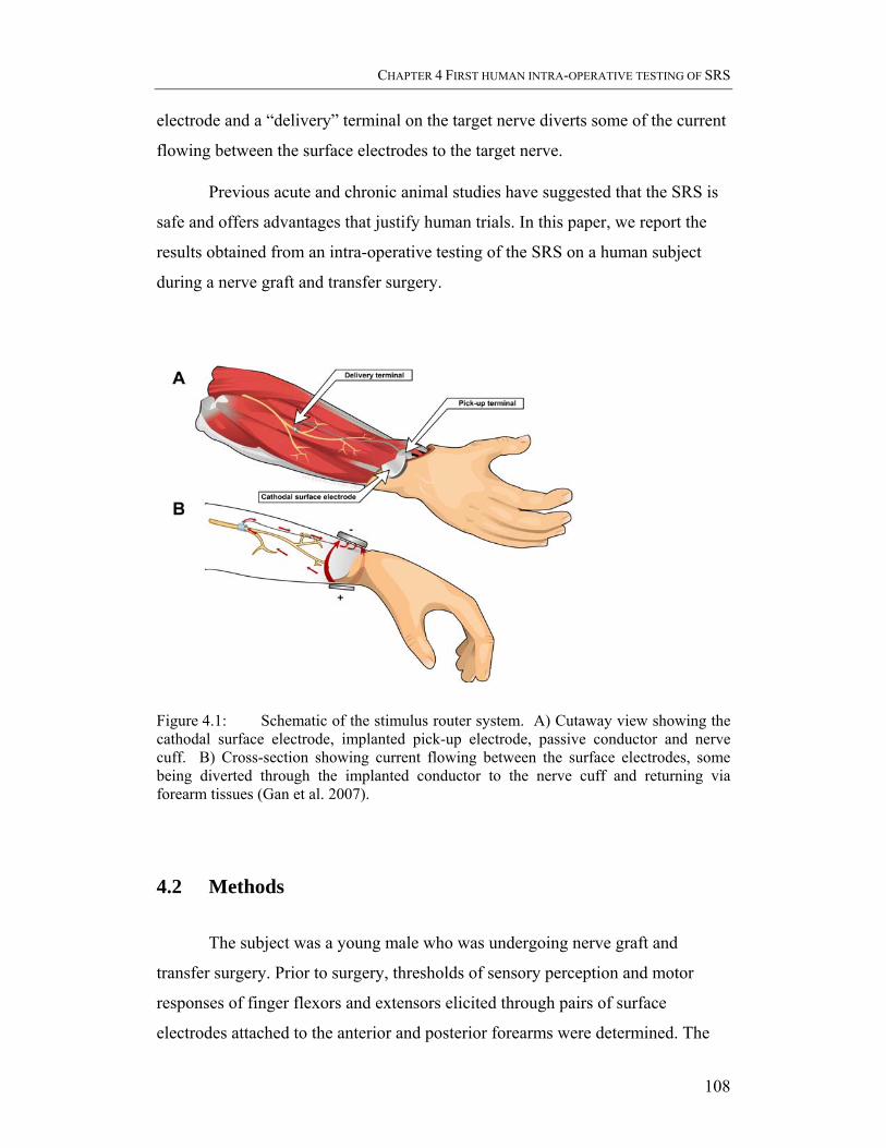
CHAPTER 4 FIRST HUMAN INTRA-OPERATIVE TESTING OF SRS
electrode and a “delivery” terminal on the target nerve diverts some of the current
flowing between the surface electrodes to the target nerve.
Previous acute and chronic animal studies have suggested that the SRS is
safe and offers advantages that justify human trials. In this paper, we report the
results obtained from an intra-operative testing of the SRS on a human subject
during a nerve graft and transfer surgery.
Figure 4.1: Schematic of the stimulus router system. A) Cutaway view showing the cathodal surface electrode, implanted pick-up electrode, passive conductor and nerve cuff. B) Cross-section showing current flowing between the surface electrodes, some being diverted through the implanted conductor to the nerve cuff and returning via forearm tissues (Gan et al. 2007).
4.2 Methods
The subject was a young male who was undergoing nerve graft and
transfer surgery. Prior to surgery, thresholds of sensory perception and motor
responses of finger flexors and extensors elicited through pairs of surface
electrodes attached to the anterior and posterior forearms were determined. The
108
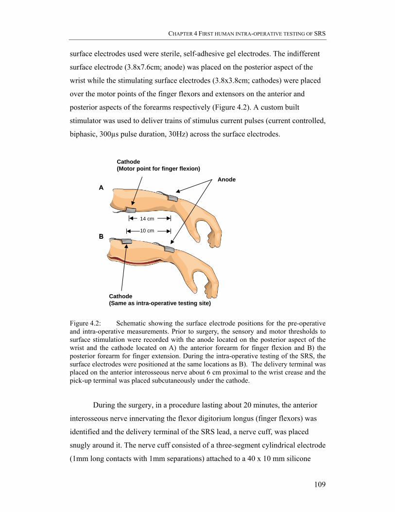
CHAPTER 4 FIRST HUMAN INTRA-OPERATIVE TESTING OF SRS
surface electrodes used were sterile, self-adhesive gel electrodes. The indifferent
surface electrode (3.8x7.6cm; anode) was placed on the posterior aspect of the
wrist while the stimulating surface electrodes (3.8x3.8cm; cathodes) were placed
over the motor points of the finger flexors and extensors on the anterior and
posterior aspects of the forearms respectively (Figure 4.2). A custom built
stimulator was used to deliver trains of stimulus current pulses (current controlled,
biphasic, 300µs pulse duration, 30Hz) across the surface electrodes.
Cathode (Motor point for finger flexion)
Anode
14 cm
10 cm
Cathode (Same as intra-operative testing site)
Figure 4.2: Schematic showing the surface electrode positions for the pre-operative and intra-operative measurements. Prior to surgery, the sensory and motor thresholds to surface stimulation were recorded with the anode located on the posterior aspect of the wrist and the cathode located on A) the anterior forearm for finger flexion and B) the posterior forearm for finger extension. During the intra-operative testing of the SRS, the surface electrodes were positioned at the same locations as B). The delivery terminal was placed on the anterior interosseous nerve about 6 cm proximal to the wrist crease and the pick-up terminal was placed subcutaneously under the cathode.
During the surgery, in a procedure lasting about 20 minutes, the anterior
interosseous nerve innervating the flexor digitorium longus (finger flexors) was
identified and the delivery terminal of the SRS lead, a nerve cuff, was placed
snugly around it. The nerve cuff consisted of a three-segment cylindrical electrode
(1mm long contacts with 1mm separations) attached to a 40 x 10 mm silicone
109
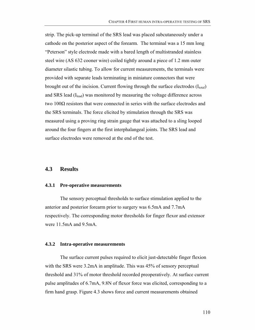
CHAPTER 4 FIRST HUMAN INTRA-OPERATIVE TESTING OF SRS
strip. The pick-up terminal of the SRS lead was placed subcutaneously under a
cathode on the posterior aspect of the forearm. The terminal was a 15 mm long
“Peterson” style electrode made with a bared length of multistranded stainless
steel wire (AS 632 cooner wire) coiled tightly around a piece of 1.2 mm outer
diameter silastic tubing. To allow for current measurements, the terminals were
provided with separate leads terminating in miniature connectors that were
brought out of the incision. Current flowing through the surface electrodes (Itotal)
and SRS lead (Ilead) was monitored by measuring the voltage difference across
two 100Ω resistors that were connected in series with the surface electrodes and
the SRS terminals. The force elicited by stimulation through the SRS was
measured using a proving ring strain gauge that was attached to a sling looped
around the four fingers at the first interphalangeal joints. The SRS lead and
surface electrodes were removed at the end of the test.
4.3 Results
4.3.1 Pre-operative measurements
The sensory perceptual thresholds to surface stimulation applied to the
anterior and posterior forearm prior to surgery was 6.5mA and 7.7mA
respectively. The corresponding motor thresholds for finger flexor and extensor
were 11.5mA and 9.5mA.
4.3.2 Intra-operative measurements
The surface current pulses required to elicit just-detectable finger flexion
with the SRS were 3.2mA in amplitude. This was 45% of sensory perceptual
threshold and 31% of motor threshold recorded preoperatively. At surface current
pulse amplitudes of 6.7mA, 9.8N of flexor force was elicited, corresponding to a
firm hand grasp. Figure 4.3 shows force and current measurements obtained
110
CHAPTER 4 FIRST HUMAN INTRA-OPERATIVE TESTING OF SRS
during this procedure. Figure 4.3C shows that only about 1.9 % of the surface
current was diverted though the SRS lead to the target nerve (Ilead = 130µA). This
is lower than the percentage we expected from animal experiments. Nonetheless
the surface current required to produce muscle contractions was still below
sensory perceptual threshold. The results suggest that the SRS can activate a
useful range of target muscle contractions without causing discomfort or pain in
the user.
Figure 4.3: Force and current measurements obtained during intra-operative testing of the SRS. A) The flexor force elicited through the SRS when trains of stimulus current pulses of 6.7mA (biphasic, 300µs pulse duration, 30 Hz) were delivered through surface electrodes located on the posterior forearm of the subject. B) Surface current pulse profile; C) current pulse profile in the implanted SRS lead (Ilead).
111
CHAPTER 4 FIRST HUMAN INTRA-OPERATIVE TESTING OF SRS
4.4 Discussion
From our animal studies, we have found that ~10% of the surface current
was diverted through the SRS lead to the target nerve (Gan et al. 2007). The
percentage was much lower in this human intra-operative test. Various reasons
can contribute to such difference, including the amount of extracellular fluid
surrounding the target nerve and the size of surface electrodes. However, it is
important to note that this percentage only provides limited indication of the total
amount of surface current needed to activate the target muscles (Gan and
Prochazka 2007).
The successful intra-operative test provides proof-of-principle in a human
subject of the efficacy of the SRS. The SRS was able to elicit target muscle
contractions at current levels below the thresholds of sensory perception and
motor responses elicited through surface electrodes in the absence of the SRS.
The results suggest that the SRS can elicit strong contractions without activating
the cutaneous and motor fibres lying directly underneath the surface electrodes.
The animal experiments indicated that the surface current threshold to stimulate a
nerve increases approximately exponentially with lateral displacement of the
surface electrode from the optimal position over the pick-up terminal (Gan et al.
2007). At 3cm displacement from the optimal position, thresholds were typically
elevated by an order of magnitude. Lead terminal spacing of 2 to 3cm will
therefore probably be required to avoid cross-talk reliably. This will limit the
number of separate SRS channels to two or three when the anatomical location of
the terminals is restricted in area (e.g. at the wrist of small subjects).
The SRS has the advantage of improved selectivity compared to external
NPs while avoiding some of the costs and complications associated with
implanted NPs. The first permanent SRS implant to restore hand opening and
grasp was performed in a quadriplegic man on 10 June 2008.
112
CHAPTER 4 FIRST HUMAN INTRA-OPERATIVE TESTING OF SRS
4.5 References
Gan LS, and Prochazka A. Characterization and optimization of the Stimulus Router System, a novel neuroprosthesis. In: Annual international functional electrical stimulation society conference. Philadelphia, PA: 2007.
Gan LS, Prochazka A, Bornes TD, Denington AA, and Chan KM. A new means of transcutaneous coupling for neural prostheses. IEEE Trans Biomed Eng 54: 509-517, 2007.
Peckham PH, and Knutson JS. Functional electrical stimulation for neuromuscular applications. Annu Rev Biomed Eng 7: 327-360, 2005.
113
Chapter 5
A novel neural prosthesis for restoration of hand opening and closing in a tetraplegic man: A pilot study
5.1 Introduction
More than 100,000 people in North America have weak or paralyzed
hands and arms due to spinal cord injury (SCI) (Center 2009). An additional 2
million stroke survivors have unilateral paresis of the upper extremity (Lloyd-
Jones et al. 2009). Restoration of arm and hand function is the highest priority
among people with tetraplegia (Hanson and Franklin 1976; Anderson 2004).
Current rehabilitation strategies include exercise therapy, splinting to avoid
development of contractures, teaching adaptive movement and restraining the use
of the less affected limb to force the use of the more affected limb (Constraint-
Induced Movement Therapy, CIMT) (Taub et al. 2006). If strength and voluntary
control of the proximal musculature are retained, tendon transfer surgery can be
performed to extend control to the distal, paralyzed muscles (Waters et al. 1996).
While these treatments can improve upper extremity function, they are
often inadequate and sometimes inappropriate, depending on the nature of the
impairment. For example, exercise therapy will produce limited functional
114
CHAPTER 5 SRS FOR RESTORATION OF HAND OPENING AND CLOSING
recovery if voluntary control is minimal or lacking or if spastic hypertonus
precludes functional grasp and release. Tendon transfers for restoration of grasp
or pinch involve extensive surgery with relatively long healing times and
expensive re-training. They are also not suitable if the proximal musculature is
weak. In these cases, restoration of function can be achieved by application of
trains of electrical stimuli to the muscle nerves to elicit functional contractions of
the innervated, yet paralyzed muscles. This treatment is referred as functional
electrical stimulation (FES) (Peckham and Knutson 2005). In contrast to the use
of electrical stimulation for therapeutic applications, where the goal is to achieve
long-term functional improvements by inducing physiological changes, FES
systems aim to supplement or replace lost neurological functions with artificial
stimulation. They are therefore also referred to as neural prostheses (NPs).
Currently available NPs for restoration of upper extremity function include
surface (Rebersek and Vodovnik 1973; van Overeem Hansen 1979; Nathan 1994;
Prochazka et al. 1997; Popovic et al. 1998; Keller et al. 2002) and implanted
systems (Peckham et al. 1988; Smith et al. 1998; Spensley 2007). Surface NPs
deliver electrical stimuli through an external stimulator and pairs of surface
electrodes attached to the skin, usually over the motor points of the targeted
muscles. These systems are technologically simple, noninvasive and relatively
inexpensive. However, they often have inadequate selectivity in terms of
stimulating individual muscles, as current delivered through the tissue under the
electrodes inevitably excites other neighboring, non-targeted sensory or motor
nerve fibres, causing pain or undesired movements. Accurate placement of
surface electrodes is essential in these systems to elicit the desired response. This
tends to require skill and patience. With implanted NPs, the electrical stimulator
and leads terminating in epimysial or nerve electrodes are surgically implanted in
the body. Command signals, and in some cases power, are transmitted from an
external control unit to the implanted stimulator through an induction coiled
placed on the skin, directly over the region of the implanted device. These
systems have better selectivity compared to the surface systems, but they are
expensive and inaccessible for repair or maintenance. Invasive surgeries are often
115
CHAPTER 5 SRS FOR RESTORATION OF HAND OPENING AND CLOSING
required with implanted systems, though minimally invasive implantation has
recently been made possible with the development of BION microstimulators
(Loeb et al. 2006).
We have developed a new type of NP, the Stimulus Router System (SRS)
(Gan et al. 2007). As in previous surface FES devices such as the Bionic Glove
(Prochazka et al. 1997), an external stimulator incorporated in a wristlet-like
garment, is used to deliver electrical stimuli via surface electrodes attached to the
skin (Figure 5.1). The novel component of the SRS is a passive conductor that is
implanted in the body. The conductor comprises an insulated lead with two
conductive terminals: one terminal is located under the skin, underlying one of the
surface electrodes (the ‘pick-up’ terminal); the other terminal is a nerve electrode
attached to the target nerve (the ‘delivery’ terminal). Some of the current flowing
between the surface electrodes is ‘captured’ by the implanted lead at the pick-up
terminal, routed to the target nerve and delivered to it at the delivery terminal. The
SRS thus eliminates some of the complications and costs related to an implanted
stimulator while retaining the selectivity of implanted NPs. The pick-up terminals
can be strategically located to allow convenient placement of the external
components (surface electrodes and stimulator garment) to lessen the burden of
daily donning and doffing. A wireless tooth-click sensor worn behind the patient’s
ear allows for telemetric control of the stimulator. Alternatively, triggering of the
electrical pulses can also be achieved through light tapping on the stimulator or on
the forearm or hand.
After a series of animal experiments showing proof-of-principle (Gan et
al. 2007; Gan and Prochazka 2009), the SRS concept was tested intra-operatively
during a human nerve transfer surgery in Jan 2008 (Prochazka et al. 2008). The
delivery end of an SRS lead was placed temporarily on the anterior interosseous
nerve innervating the finger flexors. The pick-up end of a second lead was
inserted subcutaneously to a location under a surface electrode on the posterior
forearm. The other ends of the two leads were connected through a 100 ohm
resistor to allow current to be measured. The surface current pulses required to
116
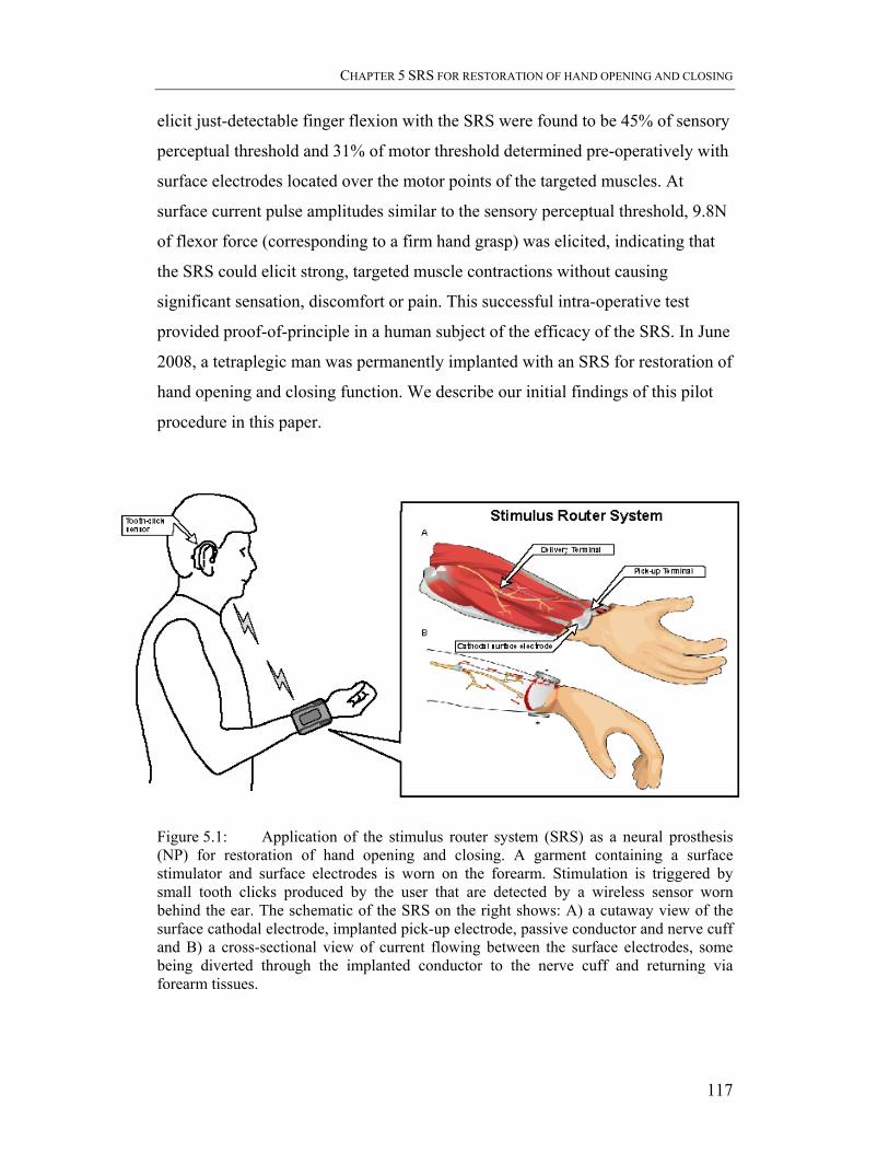
CHAPTER 5 SRS FOR RESTORATION OF HAND OPENING AND CLOSING
elicit just-detectable finger flexion with the SRS were found to be 45% of sensory
perceptual threshold and 31% of motor threshold determined pre-operatively with
surface electrodes located over the motor points of the targeted muscles. At
surface current pulse amplitudes similar to the sensory perceptual threshold, 9.8N
of flexor force (corresponding to a firm hand grasp) was elicited, indicating that
the SRS could elicit strong, targeted muscle contractions without causing
significant sensation, discomfort or pain. This successful intra-operative test
provided proof-of-principle in a human subject of the efficacy of the SRS. In June
2008, a tetraplegic man was permanently implanted with an SRS for restoration of
hand opening and closing function. We describe our initial findings of this pilot
procedure in this paper.
Figure 5.1: Application of the stimulus router system (SRS) as a neural prosthesis (NP) for restoration of hand opening and closing. A garment containing a surface stimulator and surface electrodes is worn on the forearm. Stimulation is triggered by small tooth clicks produced by the user that are detected by a wireless sensor worn behind the ear. The schematic of the SRS on the right shows: A) a cutaway view of the surface cathodal electrode, implanted pick-up electrode, passive conductor and nerve cuff and B) a cross-sectional view of current flowing between the surface electrodes, some being diverted through the implanted conductor to the nerve cuff and returning via forearm tissues.
117
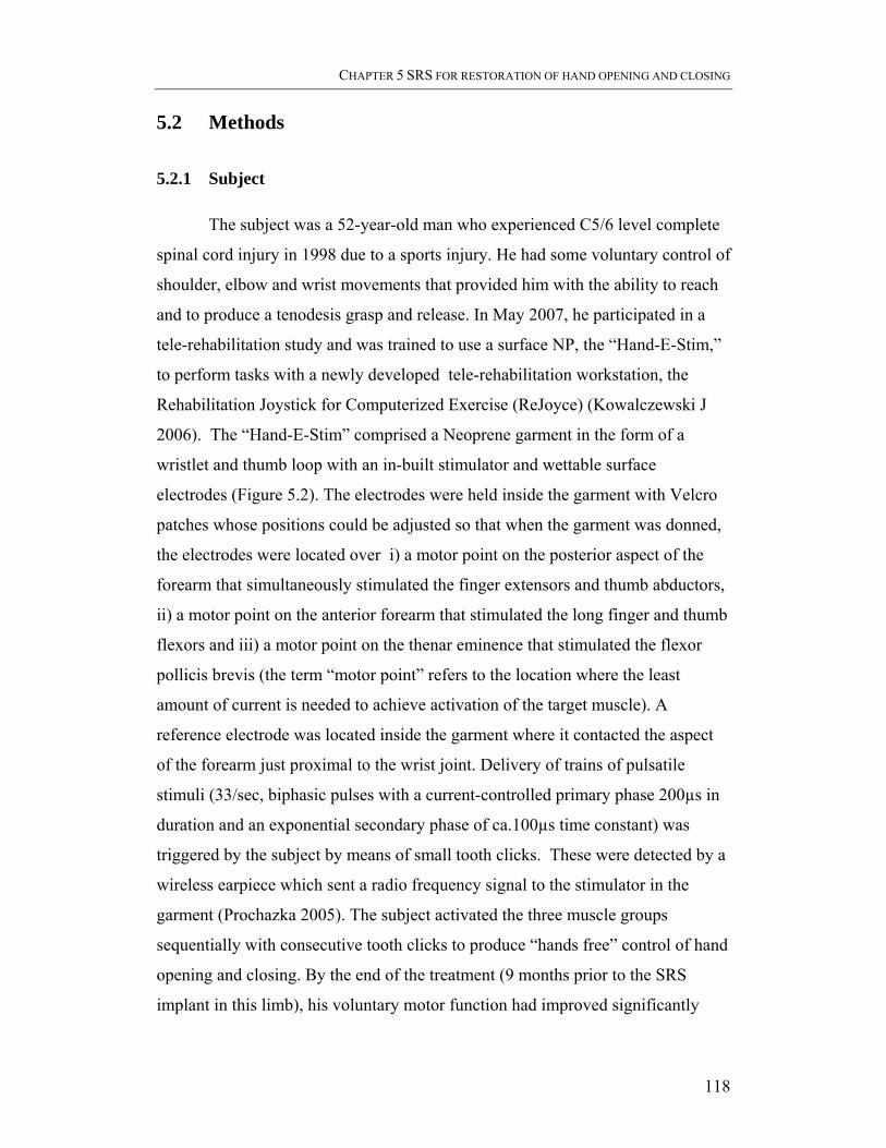
CHAPTER 5 SRS FOR RESTORATION OF HAND OPENING AND CLOSING
5.2 Methods
5.2.1 Subject
The subject was a 52-year-old man who experienced C5/6 level complete
spinal cord injury in 1998 due to a sports injury. He had some voluntary control of
shoulder, elbow and wrist movements that provided him with the ability to reach
and to produce a tenodesis grasp and release. In May 2007, he participated in a
tele-rehabilitation study and was trained to use a surface NP, the “Hand-E-Stim,”
to perform tasks with a newly developed tele-rehabilitation workstation, the
Rehabilitation Joystick for Computerized Exercise (ReJoyce) (Kowalczewski J
2006). The “Hand-E-Stim” comprised a Neoprene garment in the form of a
wristlet and thumb loop with an in-built stimulator and wettable surface
electrodes (Figure 5.2). The electrodes were held inside the garment with Velcro
patches whose positions could be adjusted so that when the garment was donned,
the electrodes were located over i) a motor point on the posterior aspect of the
forearm that simultaneously stimulated the finger extensors and thumb abductors,
ii) a motor point on the anterior forearm that stimulated the long finger and thumb
flexors and iii) a motor point on the thenar eminence that stimulated the flexor
pollicis brevis (the term “motor point” refers to the location where the least
amount of current is needed to achieve activation of the target muscle). A
reference electrode was located inside the garment where it contacted the aspect
of the forearm just proximal to the wrist joint. Delivery of trains of pulsatile
stimuli (33/sec, biphasic pulses with a current-controlled primary phase 200µs in
duration and an exponential secondary phase of ca.100µs time constant) was
triggered by the subject by means of small tooth clicks. These were detected by a
wireless earpiece which sent a radio frequency signal to the stimulator in the
garment (Prochazka 2005). The subject activated the three muscle groups
sequentially with consecutive tooth clicks to produce “hands free” control of hand
opening and closing. By the end of the treatment (9 months prior to the SRS
implant in this limb), his voluntary motor function had improved significantly
118
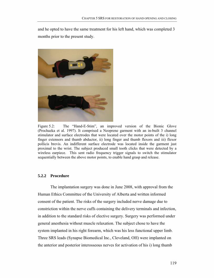
CHAPTER 5 SRS FOR RESTORATION OF HAND OPENING AND CLOSING
and he opted to have the same treatment for his left hand, which was completed 3
months prior to the present study.
Figure 5.2: The “Hand-E-Stim”, an improved version of the Bionic Glove (Prochazka et al. 1997). It comprised a Neoprene garment with an in-built 3 channel stimulator and surface electrodes that were located over the motor points of the i) long finger extensors and thumb abductor, ii) long finger and thumb flexors and iii) flexor pollicis brevis. An indifferent surface electrode was located inside the garment just proximal to the wrist. The subject produced small tooth clicks that were detected by a wireless earpiece. This sent radio frequency trigger signals to switch the stimulator sequentially between the above motor points, to enable hand grasp and release.
5.2.2 Procedure
The implantation surgery was done in June 2008, with approval from the
Human Ethics Committee of the University of Alberta and written informed
consent of the patient. The risks of the surgery included nerve damage due to
constriction within the nerve cuffs containing the delivery terminals and infection,
in addition to the standard risks of elective surgery. Surgery was performed under
general anesthesia without muscle relaxation. The subject chose to have the
system implanted in his right forearm, which was his less functional upper limb.
Three SRS leads (Synapse Biomedical Inc., Cleveland, OH) were implanted on
the anterior and posterior interosseous nerves for activation of his i) long thumb
119
CHAPTER 5 SRS FOR RESTORATION OF HAND OPENING AND CLOSING
flexor (flexor pollicis longus, FPL), ii) finger flexors (flexor digitorum profundus,
FDP) and iii) finger extensors (extensor digitorum communis, EDC) and thumb
abductor (abductor pollicis longus, APL).
(A)
(B) Figure 5.3: A) Identification of the branch of the posterior interosseous nerve innervating the finger extensors (extensor digitorium communis EDC) and thumb abductor (abductor pollicis longus APL). B) Two SRS delivery terminals were implanted on the branches of the anterior interosseous nerve that innervate the long finger flexor (flexor digitorium profundus FDP) and thumb adductor (flexor pollicis longus FPL). Two small skin incisions (~3cm) were made about 3 to 6cm proximal to the posterior and anterior wrist creases. The leads were tunneled under the skin and the pick-up terminals were anchored subcutaneouosly ~3cm and ~4cm proximal to the posterior and anterior wrist respectively.
120
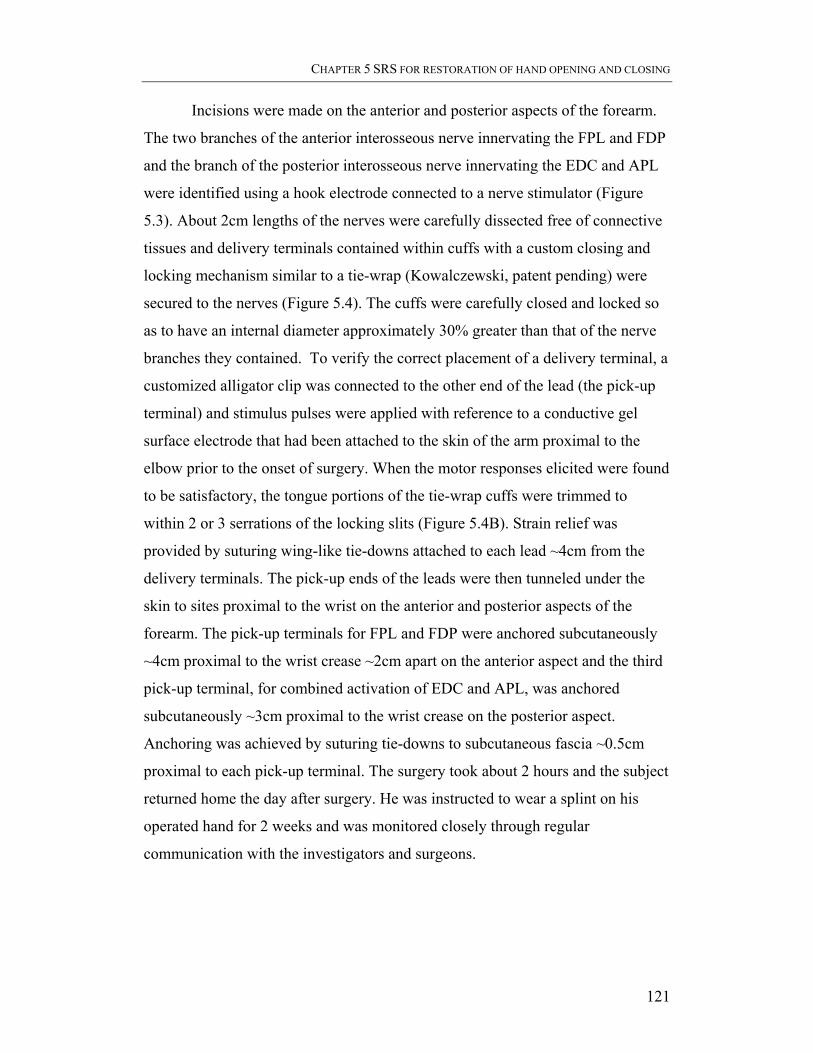
CHAPTER 5 SRS FOR RESTORATION OF HAND OPENING AND CLOSING
Incisions were made on the anterior and posterior aspects of the forearm.
The two branches of the anterior interosseous nerve innervating the FPL and FDP
and the branch of the posterior interosseous nerve innervating the EDC and APL
were identified using a hook electrode connected to a nerve stimulator (Figure
5.3). About 2cm lengths of the nerves were carefully dissected free of connective
tissues and delivery terminals contained within cuffs with a custom closing and
locking mechanism similar to a tie-wrap (Kowalczewski, patent pending) were
secured to the nerves (Figure 5.4). The cuffs were carefully closed and locked so
as to have an internal diameter approximately 30% greater than that of the nerve
branches they contained. To verify the correct placement of a delivery terminal, a
customized alligator clip was connected to the other end of the lead (the pick-up
terminal) and stimulus pulses were applied with reference to a conductive gel
surface electrode that had been attached to the skin of the arm proximal to the
elbow prior to the onset of surgery. When the motor responses elicited were found
to be satisfactory, the tongue portions of the tie-wrap cuffs were trimmed to
within 2 or 3 serrations of the locking slits (Figure 5.4B). Strain relief was
provided by suturing wing-like tie-downs attached to each lead ~4cm from the
delivery terminals. The pick-up ends of the leads were then tunneled under the
skin to sites proximal to the wrist on the anterior and posterior aspects of the
forearm. The pick-up terminals for FPL and FDP were anchored subcutaneously
~4cm proximal to the wrist crease ~2cm apart on the anterior aspect and the third
pick-up terminal, for combined activation of EDC and APL, was anchored
subcutaneously ~3cm proximal to the wrist crease on the posterior aspect.
Anchoring was achieved by suturing tie-downs to subcutaneous fascia ~0.5cm
proximal to each pick-up terminal. The surgery took about 2 hours and the subject
returned home the day after surgery. He was instructed to wear a splint on his
operated hand for 2 weeks and was monitored closely through regular
communication with the investigators and surgeons.
121
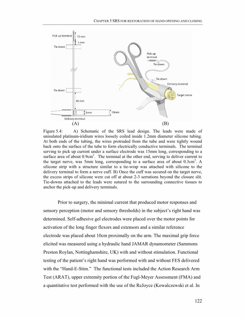
CHAPTER 5 SRS FOR RESTORATION OF HAND OPENING AND CLOSING
(A) (B)
Figure 5.4: A) Schematic of the SRS lead design. The leads were made of unisulated platinum-iridium wires loosely coiled inside 1.2mm diameter silicone tubing. At both ends of the tubing, the wires protruded from the tube and were tightly wound back onto the surface of the tube to form electrically conductive terminals. The terminal serving to pick up current under a surface electrode was 15mm long, corresponding to a surface area of about 0.9cm2. The terminal at the other end, serving to deliver current to the target nerve, was 5mm long, corresponding to a surface area of about 0.3cm2. A silicone strip with a structure similar to a tie-wrap was attached with silicone to the delivery terminal to form a nerve cuff. B) Once the cuff was secured on the target nerve, the excess strips of silicone were cut off at about 2-3 serrations beyond the closure slit. Tie-downs attached to the leads were sutured to the surrounding connective tissues to anchor the pick-up and delivery terminals.
Prior to surgery, the minimal current that produced motor responses and
sensory perception (motor and sensory thresholds) in the subject’s right hand was
determined. Self-adhesive gel electrodes were placed over the motor points for
activation of the long finger flexors and extensors and a similar reference
electrode was placed about 10cm proximally on the arm. The maximal grip force
elicited was measured using a hydraulic hand JAMAR dynamometer (Sammons
Preston Roylan, Nottinghamshire, UK) with and without stimulation. Functional
testing of the patient’s right hand was performed with and without FES delivered
with the “Hand-E-Stim.” The functional tests included the Action Research Arm
Test (ARAT), upper extremity portion of the Fugl-Meyer Assessment (FMA) and
a quantitative test performed with the use of the ReJoyce (Kowalczewski et al. In
122
CHAPTER 5 SRS FOR RESTORATION OF HAND OPENING AND CLOSING
submission, 2009). The ARAT is a standardized, validated test that assesses the
patient’s grasp, grip, pinch and gross movements through his/her ability to handle
19 objects of different size, weight and shape (Carroll 1965; Lyle 1981). The
FMA is a performance-based impairment index that assesses upper and lower
limb motor and sensory functions (Fugl-Meyer et al. 1975). We used only the
items in the FMA that assess upper extremity motor function (UE-FMA), which
include balance, range of motion and coordination of the shoulder, elbow,
forearm, wrist and hand. Assessment of ARAT and UE-FMA were done blinded
by a physiotherapist. The ReJoyce system is a workstation comprised of a
segmented arm that presents the user with a variety of manipulanda representing
tasks of daily life (Kowalczewski J 2006). The ReJoyce Automated Hand
Function Test (RAHFT) consists of a set of standardized tasks performed on the
manipulanda that test functional range of arm motion, grasp, key-grip and
pronation-supination. Unlike existing hand function tests that all require human
judgment, the RAHFT provides an objective quantitative score. A recent
comparative study showed that the RAHFT was highly correlated with the ARAT
(Kowalczewski et al. In submission, 2009).
At the conclusion of surgery and prior to the cessation of anesthesia, the
surface currents needed to elicit visible motor responses in the three targeted
muscles with SRS were determined. Surface electrodes were attached to the skin
overlying the pick-up terminals. A muscle stimulator similar to the one in the
“Hand-E-Stim” was used to deliver pulse trains through each electrode in turn,
with the use of the proximally placed reference electrode referred to above.
Similar measurements were repeated at 10 days post surgery, weekly during the
first 2 months and monthly thereafter. In addition to current thresholds (Ithreshold),
the maximal surface current levels needed to elicit maximal grip force and hand
opening (Imax) were also monitored.
About 6 weeks after the operation, the subject was provided with a
wireless earpiece and a custom-designed Neoprene wristlet similar to the “Hand-
E-Stim” but without the thumb loop (Figure 5.5). Moistened pad surface
123
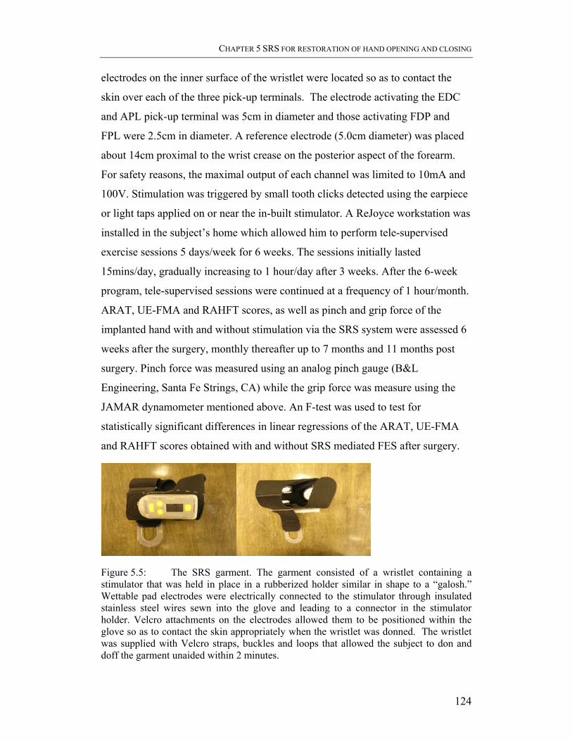
CHAPTER 5 SRS FOR RESTORATION OF HAND OPENING AND CLOSING
electrodes on the inner surface of the wristlet were located so as to contact the
skin over each of the three pick-up terminals. The electrode activating the EDC
and APL pick-up terminal was 5cm in diameter and those activating FDP and
FPL were 2.5cm in diameter. A reference electrode (5.0cm diameter) was placed
about 14cm proximal to the wrist crease on the posterior aspect of the forearm.
For safety reasons, the maximal output of each channel was limited to 10mA and
100V. Stimulation was triggered by small tooth clicks detected using the earpiece
or light taps applied on or near the in-built stimulator. A ReJoyce workstation was
installed in the subject’s home which allowed him to perform tele-supervised
exercise sessions 5 days/week for 6 weeks. The sessions initially lasted
15mins/day, gradually increasing to 1 hour/day after 3 weeks. After the 6-week
program, tele-supervised sessions were continued at a frequency of 1 hour/month.
ARAT, UE-FMA and RAHFT scores, as well as pinch and grip force of the
implanted hand with and without stimulation via the SRS system were assessed 6
weeks after the surgery, monthly thereafter up to 7 months and 11 months post
surgery. Pinch force was measured using an analog pinch gauge (B&L
Engineering, Santa Fe Strings, CA) while the grip force was measure using the
JAMAR dynamometer mentioned above. An F-test was used to test for
statistically significant differences in linear regressions of the ARAT, UE-FMA
and RAHFT scores obtained with and without SRS mediated FES after surgery.
Figure 5.5: The SRS garment. The garment consisted of a wristlet containing a stimulator that was held in place in a rubberized holder similar in shape to a “galosh.” Wettable pad electrodes were electrically connected to the stimulator through insulated stainless steel wires sewn into the glove and leading to a connector in the stimulator holder. Velcro attachments on the electrodes allowed them to be positioned within the glove so as to contact the skin appropriately when the wristlet was donned. The wristlet was supplied with Velcro straps, buckles and loops that allowed the subject to don and doff the garment unaided within 2 minutes.
124
CHAPTER 5 SRS FOR RESTORATION OF HAND OPENING AND CLOSING
5.3 Results
Prior to surgery, without FES, the patient was not able to generate a grip
force reading on the JAMAR dynamometer. Hand opening aperture measured
between the tips of the forefinger and thumb was 4 cm under voluntary control.
With surface electrodes placed over the motor points of the finger flexors and
extensors and an indifferent electrode placed on the posterior aspect of the
forearm just proximal to the wrist, the minimal amplitudes of trains of surface
current pulses needed to elicit observable finger flexion and extension were
8.5mA and 7.5mA respectively (Figure 5.6). Maximal grip force of 11N and hand
opening aperture of 10cm was achieved when the surface current amplitudes were
increased to 19mA and 17mA for maximal activation of the finger flexors and
extensors respectively. The patient’s sensory perceptual thresholds to surface
stimulation were also tested by placing pairs of surface electrodes at 6 different
locations on his forearm. The sensory thresholds averaged 6.1 mA + 1.4mA SD.
Although the current levels needed to activate maximal grip or hand opening were
much higher than the sensory perceptual thresholds, they were well tolerated and
the patient did not report significant discomfort or painful sensations.
Immediately after the SRS leads were implanted, one surface electrode
was placed overlying the two pick-up terminals on the anterior forearm to co-
activate FPL and FDP and another surface electrode was placed overlying the
pick-up terminal on the posterior forearm to activate the EDC and APL. An
indifferent electrode was placed about 11cm proximally on the posterior aspect of
the forearm. The minimal surface currents needed for activation of the hand
closing muscles (FPL and FDP) and hand opening muscles (EDC and APL) with
SRS (Ithreshold) were 1.3mA and 1.8mA respectively (15% and 24% of the motor
thresholds with conventional surface stimulation prior to surgery). Ten days after
surgery, the patient returned to the laboratory for testing of the implants. Surface
electrodes were placed over each implanted pick-up terminal and an indifferent
electrode was again placed about 11cm proximally on the posterior aspect of the
forearm. The activation thresholds of FPL, FDP and EDC with SRS were 2.0mA,
125
CHAPTER 5 SRS FOR RESTORATION OF HAND OPENING AND CLOSING
1.75mA and 2.75mA respectively. With one surface electrode overlying the two
pick-up terminals on the anterior forearm to co-activate FPL and FDP, a maximal
grip force of 83N was elicited at a surface current of 3mA (Imax). This force was
about 7.5 times higher than the maximal grip force elicited with surface
stimulation prior to surgery. Also, the surface current needed to elicit such force
with SRS was 50% of the subject’s sensory perceptual threshold and 35% of the
motor threshold of the same muscles prior to surgery, with conventional surface
stimulation. Close observation of the tissues around the surface electrodes
confirmed that the current levels were low enough such that no non-targeted
muscles were co-activated with the targeted muscles. The subject demonstrated
the ability to squeeze a pop can and perform a hand shake as the surface current
level was gradually increased to the appropriate functional levels, indicating that
selective and graded activation of the target nerves is achievable with the SRS.
During the test session he was provided with a wireless earpiece with which he
was able to trigger stimulation of extensors and flexors sequentially by clicking
his teeth to open and close his hand and to hold on firmly to a water bottle. When
the subject was asked to describe his sensation during muscle activation with the
SRS, he replied that he only felt the “pulling” of the muscles as they were
activated but did not feel the tingling sensation in his skin that he had felt with
conventional surface stimulation.
We monitored Ithreshold, Imax, the maximal grip force elicited and thumb to
finger separations at intervals of 2 to 4 weeks up to 10 months post-surgery
(Figure 5.6). In each grip force measurement, the stimulation level was increased
by the experimenter to the point that no further increase in force occurred.
Similar to our observations in the chronic animal studies (Gan et al. 2007), Ithreshold
and Imax fluctuated and slightly increased for the first 2 months but stabilized and
then decreased over time (Figures 5.6A-B). Figure 5.6C shows that the maximal
grip force decreased substantially after the first post-op test session at day 10.
This was possibly due to weakness after the 10 days of immobilization and tissue
recovery after surgery. Despite variations in the maximal grip strength measured
over time, the force level showed an increasing trend over the monitored period.
126
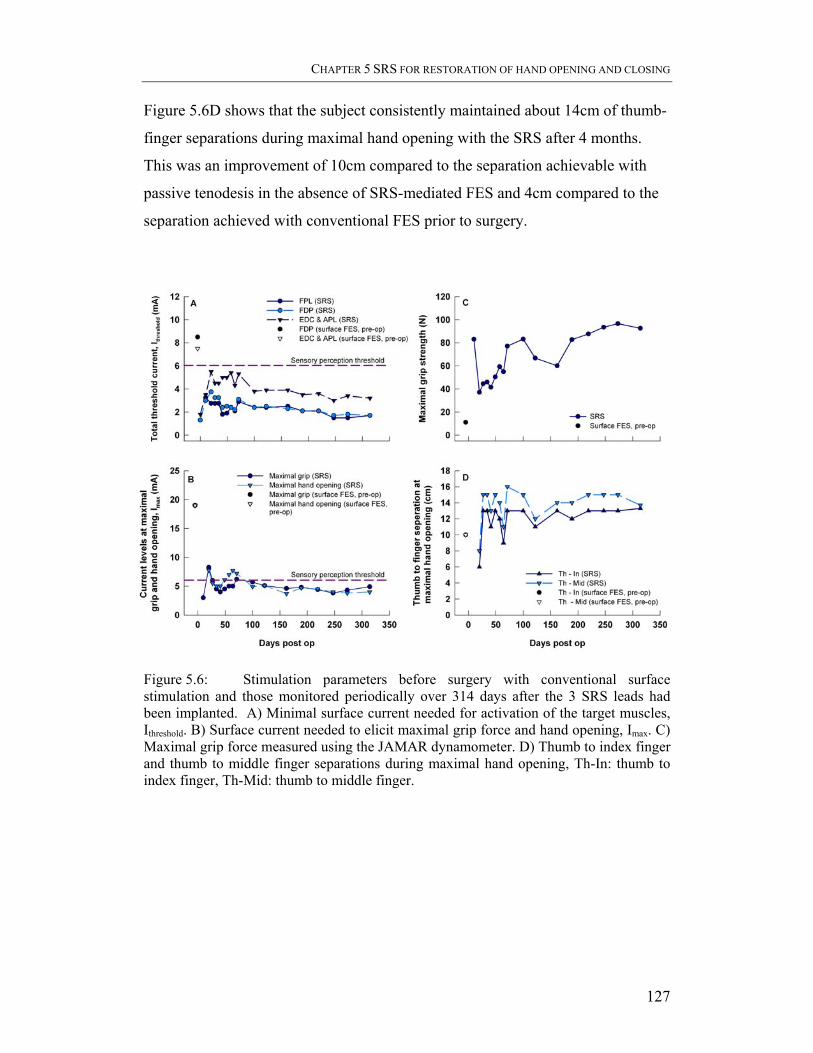
CHAPTER 5 SRS FOR RESTORATION OF HAND OPENING AND CLOSING
Figure 5.6D shows that the subject consistently maintained about 14cm of thumb-
finger separations during maximal hand opening with the SRS after 4 months.
This was an improvement of 10cm compared to the separation achievable with
passive tenodesis in the absence of SRS-mediated FES and 4cm compared to the
separation achieved with conventional FES prior to surgery.
Figure 5.6: Stimulation parameters before surgery with conventional surface stimulation and those monitored periodically over 314 days after the 3 SRS leads had been implanted. A) Minimal surface current needed for activation of the target muscles, Ithreshold. B) Surface current needed to elicit maximal grip force and hand opening, Imax. C) Maximal grip force measured using the JAMAR dynamometer. D) Thumb to index finger and thumb to middle finger separations during maximal hand opening, Th-In: thumb to index finger, Th-Mid: thumb to middle finger.
127
CHAPTER 5 SRS FOR RESTORATION OF HAND OPENING AND CLOSING
Figure 5.7 shows the patient’s ARAT, UE-FMA and RAHFT scores
without FES, using “Hand-E-Stim” conventional FES (before surgery) and SRS-
FES (after surgery). There was no apparent improvement over time in the hand
function tests in Figure 5.7. This may be related to the subject’s relatively high
mean ARAT score without FES prior to surgery (37.5 out of a possible 57),
indicating that his hand was in the upper range of functionality for people with his
level of injury. Furthermore, as mentioned in Methods, 9 months prior to the
implant he had completed a study involving 16 weeks of exercise therapy, which
may have limited any further improvements to be gained from daily usage of the
SRS device.
The more surprising outcome was that the mean ARAT scores without
FES were higher than those with FES both before surgery (37.5 cf. 36) and after
surgery (41+3.1SD cf. 37.8+4.2SD) though the difference was not statistically
significant (p = 0.15), On the other hand, the mean UE-FMA scores after surgery
were significantly higher with FES than without FES (33+1.8 cf. 28.9+2.9, p =
0.004). As in the ARAT, the mean RAHFT scores did not show a significant
difference between tests with and without FES (46.1+11.5 cf. 40.9+12.1, p =
0.22), although the scores did tend to be slightly higher with SRS-FES than
without FES in the first 3 months of using the device, but not from months 5 to 9.
The ARAT results are puzzling, given the significant improvements in pinch and
grasp force and extent of hand opening with FES shown in Figure 5.6. Although
functions such as range of motion, finger dexterity and the manipulation of light
objects are well represented in the ARAT, tasks requiring wide-aperture hand
opening and strong grasp and pinch grip are less well represented. The ARAT
may therefore not be particularly well suited to detect the types of improvement
resulting from FES, a fact that has been noted previously in the literature (van
Tuijl et al. 2002; Mulcahey et al. 2007). This will be further considered in the
Discussion.
128
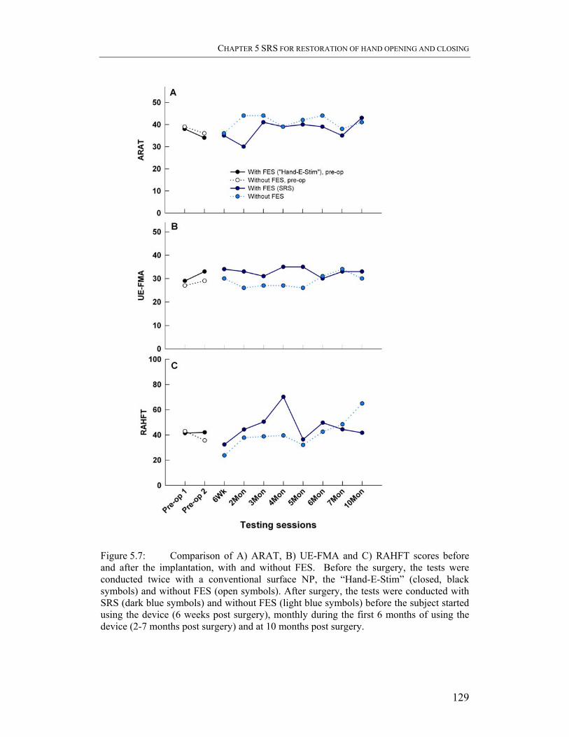
CHAPTER 5 SRS FOR RESTORATION OF HAND OPENING AND CLOSING
Figure 5.7: Comparison of A) ARAT, B) UE-FMA and C) RAHFT scores before and after the implantation, with and without FES. Before the surgery, the tests were conducted twice with a conventional surface NP, the “Hand-E-Stim” (closed, black symbols) and without FES (open symbols). After surgery, the tests were conducted with SRS (dark blue symbols) and without FES (light blue symbols) before the subject started using the device (6 weeks post surgery), monthly during the first 6 months of using the device (2-7 months post surgery) and at 10 months post surgery.
129
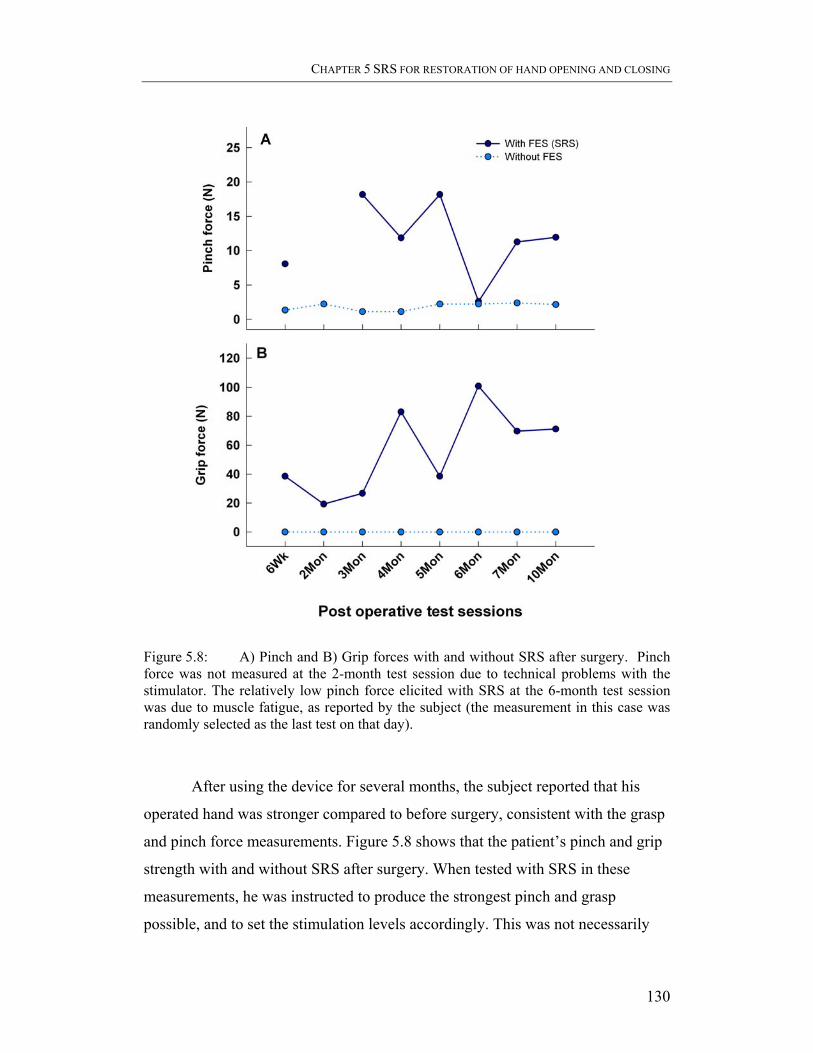
CHAPTER 5 SRS FOR RESTORATION OF HAND OPENING AND CLOSING
Figure 5.8: A) Pinch and B) Grip forces with and without SRS after surgery. Pinch force was not measured at the 2-month test session due to technical problems with the stimulator. The relatively low pinch force elicited with SRS at the 6-month test session was due to muscle fatigue, as reported by the subject (the measurement in this case was randomly selected as the last test on that day).
After using the device for several months, the subject reported that his
operated hand was stronger compared to before surgery, consistent with the grasp
and pinch force measurements. Figure 5.8 shows that the patient’s pinch and grip
strength with and without SRS after surgery. When tested with SRS in these
measurements, he was instructed to produce the strongest pinch and grasp
possible, and to set the stimulation levels accordingly. This was not necessarily
130

CHAPTER 5 SRS FOR RESTORATION OF HAND OPENING AND CLOSING
the level that produced maximal muscle activation in the pinch tests (unlike the
tests illustrated in Figure 5.6C, because maximal activation tended to cause
extreme flexion of the distal thumb joint, which in turn caused the thumb to slip
off the end of the pinch-gauge. The subject’s pinch and grip force improve
substantially with the aid of the SRS. Without SRS, the pinch force showed a
slight increase over time while the grip force remained too low to be detected by
the dynamometer. At the 5-month test session, the pinch force elicited with SRS
was lower than the other test sessions, most likely due to muscle fatigue, as on
those test sessions (lasting ~ 45 minutes) the pinch force measurement was
randomly selected to be the last test of the day.
At the time of the report, the patient has been using the SRS for 12
months. He expressed satisfaction with the system and has continued to use it
daily after the initial 6-week training period. Usage was quantified by a counter in
the stimulator that recorded the total stimulation time on each channel. The
counter readings were recorded monthly. Figure 5.9A shows the mean daily usage
of the device over 9 months. From our observations during hand function testing,
10 minutes of stimulation time correspond to about 15 minutes of being engaged
in using the device for performing manual tasks. The results show that the
subject’s daily usage increased substantially after 4 months, up to about an hour a
day. Lower usage in the earlier months was attributed to self-reported muscle
fatigue and also to technical difficulties associated with the stimulator and
wireless earpiece that were gradually overcome. Once the external hardware was
improved and adjustments had been made based on the patient’s feedback, the
system was found to be more reliable and the subject became confident in using
the device to assist in activities of daily life. At month 9, the subject experienced a
shoulder injury while doing triceps training and used the SRS device less
frequently. His usage returned to about 90 minutes per day the next month after
he recovered from the injury. In the last month, the stimulator was returned to the
laboratory for repair, which explains the decline in usage in this case. Figure
5.9B shows the relative duration spent in activation of the finger flexors compared
to extensors. As expected, the flexors were activated for longer durations,
131
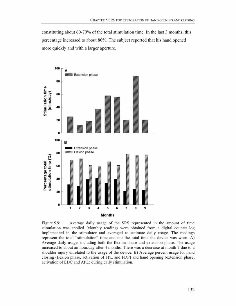
CHAPTER 5 SRS FOR RESTORATION OF HAND OPENING AND CLOSING
constituting about 60-70% of the total stimulation time. In the last 3 months, this
percentage increased to about 80%. The subject reported that his hand opened
more quickly and with a larger aperture.
Figure 5.9: Average daily usage of the SRS represented in the amount of time stimulation was applied. Monthly readings were obtained from a digital counter log implemented in the stimulator and averaged to estimate daily usage. The readings represent the total “stimulation” time and not the total time the device was worn. A) Average daily usage, including both the flexion phase and extension phase. The usage increased to about an hour/day after 4 months. There was a decrease at month 7 due to a shoulder injury unrelated to the usage of the device. B) Average percent usage for hand closing (flexion phase, activation of FPL and FDP) and hand opening (extension phase, activation of EDC and APL) during daily stimulation.
132
CHAPTER 5 SRS FOR RESTORATION OF HAND OPENING AND CLOSING
5.4 Discussion
The aim of this study was to investigate the feasibility and viability of the
SRS as a new type of NP in humans. Conventional NPs consist of an implanted
stimulator, controlled by radio frequency transmission of commands and energy
from a coil antenna worn outside the body. These NPs have a large range of
applications, including cochlear nerve stimulation, deep brain stimulation, vagal
nerve stimulation and dorsal column stimulation to name just a few. We chose to
test the SRS as a motor NP in our first permanent human implant, because the
activation of nerves innervating muscles leads to responses that are unequivocal
and relatively easy to measure. Furthermore, our laboratory has been involved in
FES research for over 20 years.
The subject in this study experienced a C5/6 complete SCI 10 years before
the present study. He had taken part in a 16-week program involving daily
exercises of his right hand on a workstation, assisted with surface FES and
supervised over the Internet. On June 10 2008, 3 SRS leads were implanted in his
right forearm in a surgical procedure lasting about 2 hours. The delivery ends of
the leads, which terminated in silicone cuffs, were affixed to the nerves
controlling the long thumb flexor, finger flexors and finger extensors.
The SRS was able to selectively activate the target muscles in a graded
and controlled manner over their full physiological range at surface current levels
below those eliciting sensory perception. Muscle activation was reproducible over
the entire study period of 12 months. This provides strong support for the general
viability and efficacy of the SRS as a NP.
In the months after surgery, SRS-FES substantially increased the subject’s
grip strength and hand aperture compared to non-assisted values or with surface
FES prior to surgery. The amount of surface current needed to achieve muscle
activation with the SRS was also much lower than that required with surface FES
prior to surgery. The ratios of Imax/Ithreshold (surface current eliciting maximal
contraction /surface current just eliciting a contraction) for hand closing and
133
CHAPTER 5 SRS FOR RESTORATION OF HAND OPENING AND CLOSING
opening calculated over 16 measurements were 1.89+0.24 and 1.28+0.18
respectively. These ratios can be used as an intra-operative guideline of a
successful implant in future studies. Furthermore, if the motor thresholds with
SRS stimulation are greater than the sensory thresholds, this would be a clear
indication that one or more components of the SRS are incorrectly located.
The ARAT, UE-FMA and RAHFT were used as functional outcome
measures in our study, as they contain tasks that are encountered in activities of
daily life. The UE-FMA scores were slightly higher with SRS-FES than without.
However the ARAT and RAHFT scores indicated no significant differences. This
was a surprising result, especially in light of the clear improvements in grip force.
The majority of existing hand function tests, including the ARAT and FMA were
designed to evaluate voluntary control in disorders such as stroke. Their
advantage is that they have been tested for validity and reliability and are widely
used. However, it has been found by others, that they are not well suited to detect
the types of movements improved by FES. The Grasp and Release Test (GRT)
was designed by Wuolle et al as a more suitable test for FES interventions
(Wuolle et al. 1994). It was used as a primary outcome measure in the evaluation
of the Freehand System, a fully implanted NP for restoration of hand function in
C5/6 SCI subjects (Wuolle et al. 1994). The GRT involves manipulation of 6
objects (blocks, paper weight, fork, video tape, can and peg) and has been
preliminarily tested for reliability and validity in 12 cervical SCI patients aged
from 7-20. It was found to have good test-retest reliability and was sensitive to
changes provided by FES (Mulcahey et al. 2004), however, administration of the
GRT requires a pretest and 3 repetitions of the actual test, resulting in sessions
lasting up to an hour. Preliminary testing of our first subject with the GRT caused
significant muscle fatigue and so we decided against using it in the present study.
In contrast to the hand function test results, our subject has continued to
use the SRS on a daily basis, for a significant portion of his waking hours,
suggesting that the benefit of using the system outweighs the inconvenience of
donning and doffing the earpiece and the garment containing the stimulator. This
134
CHAPTER 5 SRS FOR RESTORATION OF HAND OPENING AND CLOSING
was confirmed by the subject when he described the functional improvements to
be subtle, but important: his work efficiency improved (e.g. reduced occurrence of
disconnected phone calls due to dropping the handset, improved grasp of
documents, avoiding “scooping” or “sweeping” objects into his lap). He also
reported improvements in his quality of life (e.g. able to shake hands at social and
family gatherings, open the fridge without assistance and pick up larger and
heavier objects such as a 4L milk jar at grocery stores). He found that the fine
manipulation of small objects was better done without SRS-FES, as the relatively
strong activation of finger flexors and extensors reduced dexterity. This property
of FES is not unique to the SRS (Popovic et al. 1999). He found the smaller size
of the SRS garment (Figure 5.5) to be more comfortable and convenient than the
“Hand-E-Stim” garment (Figure 5.2) and was able to don it in about 2 minutes
without assistance. He did require assistance to reliably don the earpiece, so we
have provided an alternative triggering method in the form of a 3-axis
accelerometer in the stimulator which detected light tapping on the stimulator or
forearm. The two methods of controlling stimulation allowed him to trigger the
SRS only in tasks in which it was beneficial.
The SRS provided several advantages over existing motor NP systems.
Greater selectivity was achieved compared to conventional surface stimulation
because current was routed directly to deep-lying nerves through the implanted
leads. Unlike surface FES systems, where the electrodes must be placed over
motor points which may be widely distributed and in inconvenient locations,
several SRS leads can be routed subcutaneously to a convenient location, in this
case just proximal to the wrist. As a result, the external garments containing the
surface electrodes and stimulator are much smaller, easier to don and doff, more
comfortable and attract less attention. Without an implanted stimulator, the
surgical procedure is shorter and less invasive, reducing surgical costs, risk of
infection and time of recovery. Implanted stimulators tend to be too large to be
located within the upper extremity. In the case of the Freehand system, the
stimulator is implanted in the chest wall, which requires its leads to be tunneled
across joints, which carries the risk of eventual lead failures in the long term.
135
CHAPTER 5 SRS FOR RESTORATION OF HAND OPENING AND CLOSING
However, the need in the SRS for surface electrodes to make good electrical
contact with the skin is a drawback compared to inductive coupling. The SRS is
also limited in the number of individual stimulation channels that can be
provided, since each additional lead requires a surface electrode occupying a
minimum of 7cm2 of skin surface (20 mm diameter electrodes, 15mm centre to
centre) (Gan et al. 2007; Gan and Prochazka 2009). In applications requiring more
than four channels a fully implanted NP may remain the device of choice.
In conclusion, the results obtained from this pilot study of the SRS in a
human indicated that it is a viable alternative to currently existing motor NPs.
Powerful muscle contractions were generated in the absence of skin sensations
under the surface electrodes, confirming the results of the animal experiments
leading up to the present study. The SRS achieved stronger muscle contractions,
better selectivity and more convenience than surface stimulation. NPs based on
the SRS concept are likely to be less invasive and costly than conventional
implanted NPs, though they may not be able to support as many channels. The
external components of the SRS can be miniaturized so as to be no larger than a
wristwatch. We believe the results we have presented in this pilot study support
the idea that the SRS provides the basis for a new family of NPs for disorders of
the human nervous system.
136
CHAPTER 5 SRS FOR RESTORATION OF HAND OPENING AND CLOSING
5.5 References
Anderson KD. Targeting recovery: priorities of the spinal cord-injured population. J Neurotrauma 21: 1371-1383, 2004.
Carroll D. A Quantitative Test of Upper Extremity Function. J Chronic Dis 18: 479-491, 1965.
Center TNSS. Facts and figures at a glance The University of Alabama at Birmingham. http://www.spinalcord.uab.edu/show.asp?durki=119513&site=4716&return=19775.
Fugl-Meyer AR, Jaasko L, Leyman I, Olsson S, and Steglind S. The post-stroke hemiplegic patient. 1. a method for evaluation of physical performance. Scand J Rehabil Med 7: 13-31, 1975.
Gan LS, and Prochazka A. Properties of the stimulus router system, a novel neural prosthesis. IEEE Trans Biomed Eng 2009.
Gan LS, Prochazka A, Bornes TD, Denington AA, and Chan KM. A new means of transcutaneous coupling for neural prostheses. IEEE Trans Biomed Eng 54: 509-517, 2007.
Hanson RW, and Franklin MR. Sexual loss in relation to other functional losses for spinal cord injured males. Arch Phys Med Rehabil 57: 291-293, 1976.
Keller T, Popovic MR, Pappas IP, and Muller PY. Transcutaneous functional electrical stimulator "Compex Motion". Artif Organs 26: 219-223, 2002.
Kowalczewski J aPA. Method and apparatus for automated delivery of therapeutic exercises of the upper extremity. USA: 2006.
Kowalczewski J, Davies C, and Prochazka A. A fully-automated, quatitative test of upper extremity function In submission, 2009.
Lloyd-Jones D, Adams R, Carnethon M, De Simone G, Ferguson TB, et al. Heart disease and stroke statistics--2009 update: a report from the American Heart Association Statistics Committee and Stroke Statistics Subcommittee. Circulation 119: 480-486, 2009.
Loeb GE, Richmond FJ, and Baker LL. The BION devices: injectable interfaces with peripheral nerves and muscles. Neurosurg Focus 20: E2, 2006.
Lyle RC. A performance test for assessment of upper limb function in physical rehabilitation treatment and research. Int J Rehabil Res 4: 483-492, 1981.
137
CHAPTER 5 SRS FOR RESTORATION OF HAND OPENING AND CLOSING
Mulcahey MJ, Hutchinson D, and Kozin S. Assessment of upper limb in tetraplegia: considerations in evaluation and outcomes research. J Rehabil Res Dev 44: 91-102, 2007.
Mulcahey MJ, Smith BT, and Betz RR. Psychometric rigor of the Grasp and Release Test for measuring functional limitation of persons with tetraplegia: a preliminary analysis. J Spinal Cord Med 27: 41-46, 2004.
Nathan R. Device for generating hand function. edited by Patent U. USA: 1994.
Peckham PH, Keith MW, and Freehafer AA. Restoration of functional control by electrical stimulation in the upper extremity of the quadriplegic patient. J Bone Joint Surg Am 70: 144-148, 1988.
Peckham PH, and Knutson JS. Functional electrical stimulation for neuromuscular applications. Annu Rev Biomed Eng 7: 327-360, 2005.
Popovic D, Popovic M, Stojanovic A, Pjanovic A, Radosavljevic S, et al. Clinical evaluation of the Belgrade Grasping System. In: The 6th Vienna International Workshop on Functional Electrical Stimulation. Vienna, Austria: 1998, p. 247-250.
Popovic D, Stojanovic A, Pjanovic A, Radosavljevic S, Popovic M, et al. Clinical evaluation of the bionic glove. Arch Phys Med Rehabil 80: 299-304, 1999.
Prochazka A. Method and Apparatus for controlling a device or process with vibrations generated by tooth clicks., edited by Patent U2005.
Prochazka A, Gan LS, Olson J, and Morhart M. First human intra-operative testing of the Stimulus Router System. In: 13th Annual International FES Society Conference. Freiburg, Germany: 2008, p. P4.14.
Prochazka A, Gauthier M, Wieler M, and Kenwell Z. The bionic glove: an electrical stimulator garment that provides controlled grasp and hand opening in quadriplegia. Arch Phys Med Rehabil 78: 608-614, 1997.
Rebersek S, and Vodovnik L. Proportionally controlled functional electrical stimulation of hand. Arch Phys Med Rehabil 54: 378-382, 1973.
Smith B, Tang Z, Johnson MW, Pourmehdi S, Gazdik MM, et al. An externally powered, multichannel, implantable stimulator-telemeter for control of paralyzed muscle. IEEE Trans Biomed Eng 45: 463-475, 1998.
Spensley J. STIMuGRIP; a new hand control implant. Conf Proc IEEE Eng Med Biol Soc 2007: 513, 2007.
138
CHAPTER 5 SRS FOR RESTORATION OF HAND OPENING AND CLOSING
Taub E, Uswatte G, King DK, Morris D, Crago JE, et al. A placebo-controlled trial of constraint-induced movement therapy for upper extremity after stroke. Stroke 37: 1045-1049, 2006.
van Overeem Hansen G. EMG-controlled functional electrical stimulation of the paretic hand. Scand J Rehabil Med 11: 189-193, 1979.
van Tuijl JH, Janssen-Potten YJ, and Seelen HA. Evaluation of upper extremity motor function tests in tetraplegics. Spinal Cord 40: 51-64, 2002.
Waters RL, Sie IH, Gellman H, and Tognella M. Functional hand surgery following tetraplegia. Arch Phys Med Rehabil 77: 86-94, 1996.
Wuolle KS, Van Doren CL, Thrope GB, Keith MW, and Peckham PH. Development of a quantitative hand grasp and release test for patients with tetraplegia using a hand neuroprosthesis. J Hand Surg [Am] 19: 209-218, 1994.
139
Chapter 6
General discussion and conclusions
6.1 General discussion and summary
The studies presented in this thesis address the development of the SRS
from animal testing to its implementation as an upper extremity NP in a
tetraplegic subject. Chapter 2 addresses the basic properties of the SRS and
provides proof-of-principle of the system in both acute and chronic animal
studies. Long- term reliability and longevity of the system were also
demonstrated. Chapter 3 further investigated the effect of electrode configuration,
electrode design and stimulation parameters on SRS activation thresholds.
Chapter 4 provides the first human proof-of-principle of the SRS during an intra-
operative test. Chapter 5 describes the experience and results obtained in the first
human pilot study.
To be useful as a NP, the SRS should allow for selective and graded
activation of the target nerves over the full physiological range without co-
activating the non-targeted motor or sensory fibres directly underlying the surface
electrodes. Chapter 2 describes experiments to test the feasibility of the SRS as a
NP across 3 animal species (cat, rabbit and piglet). Up to 20% of the current
flowing between pairs of surface electrodes was diverted through the implanted
SRS conductor. Controlled gradation of force was possible and no unwanted,
local muscle contraction was observed. The amount of surface current needed to
140
CHAPTER 6 GENERAL DISCUSSION AND CONCLUSIONS
activate the target nerves was found to vary less than 30% for skin thicknesses
ranging from 1 mm to 5 mm. Human proof-of-principle of the SRS was first
demonstrated in the intra-operative procedure described in Chapter 4. During the
intra-operative testing, the surface current needed to elicit a strong target
contraction with the SRS was about 90% of the subject’s sensory perceptual
threshold to surface electrical stimulation measured pre-operatively. In this case,
only 1.9% of the surface current was diverted through the SRS implanted
conductor, which was rather surprising, based on what was observed in the animal
studies. Nevertheless, co-activation of the untargeted local muscles did not occur.
Finally, in the first permanent human implant described in Chapter 5, it was
demonstrated that selective activation of the 3 target muscles for hand opening
and closing was achieved with 3 SRS implanted leads. The subject did not
experience any cutaneous sensation when stimulation was delivered. In addition,
useful muscle contractions were elicited at surface current levels less than 50% of
those needed with conventional surface stimulation.
It was initially assumed that the amount of surface current needed to
activate the target nerves with SRS depended strongly on the proportion of current
‘routed’ through the implanted conductor (capture ratio). Low threshold current
level is desirable to avoid the co-activation of the non-targeted motor or sensory
fibres under the surface electrodes and to reduce the power demand of the system.
Hence, much of the initial effort in optimizing the system efficiency has focused
on increasing the capture ratio. The effects of different parameters on activation
thresholds and capture ratios are summarized in Table 6.1. In Chapter 2 and 3, it
was shown that higher capture ratios can be achieved by employing a bipolar
versus a monopolar configuration, by increasing the surface areas of the
implanted conductive terminals and by providing backing insulation to the pick-
up terminals. However, these approaches are not ideal clinically since an extra
lead will have to be implanted per stimulation channel and large conductive
terminals will have to be implanted. It was later found that the amount of current
shunting in the vicinity of the delivery terminal can have a greater effect on
activation thresholds compared to capture ratio. Hence, a more effective way of
141
CHAPTER 6 GENERAL DISCUSSION AND CONCLUSIONS
reducing SRS activation thresholds was to ensure good target nerve-delivery
terminal contact and to limit the amount of current shunting at the delivery
terminal, such as enclosing the nerve and delivery terminal in a non-conductive
nerve cuff. With the aid of a simple finite element model, the effect of several
delivery terminal configurations on SRS stimulation thresholds was investigated.
The chronic animal results showed that with delivery terminals of similar
configurations, activation thresholds can be predominantly affected by variability
in encapsulation tissue growth.
Longevity of implants and reproducibility of motor responses are essential
for long term NPs. In Chapter 2 and 3, it was shown that after initial failures with
early SRS lead prototypes, the improved SRS leads lasted up to 8 months in
chronically implanted animals. The implants in one of the animals continued to be
functional up to 2 years (unpublished data). At the time of the thesis defense, the
3 SRS leads have been implanted for 14 months in the first human subject and
remain functional, with stimulation parameters that have remained stable for over
a year. In all the chronic implants, whether in the animals or the human subject,
fluctuations in activation thresholds and force elicited were observed for the first
50-60 days after surgery. This has been attributed to inflammatory responses and
development of encapsulation tissue following implantation (Grill and Mortimer
1998). Both activation thresholds and maximal force elicited with SRS stabilized
over time. The activation thresholds gradually decreased while the force levels
gradually increased over time. The results support the idea that the SRS is reliable
as a long term NP.
142
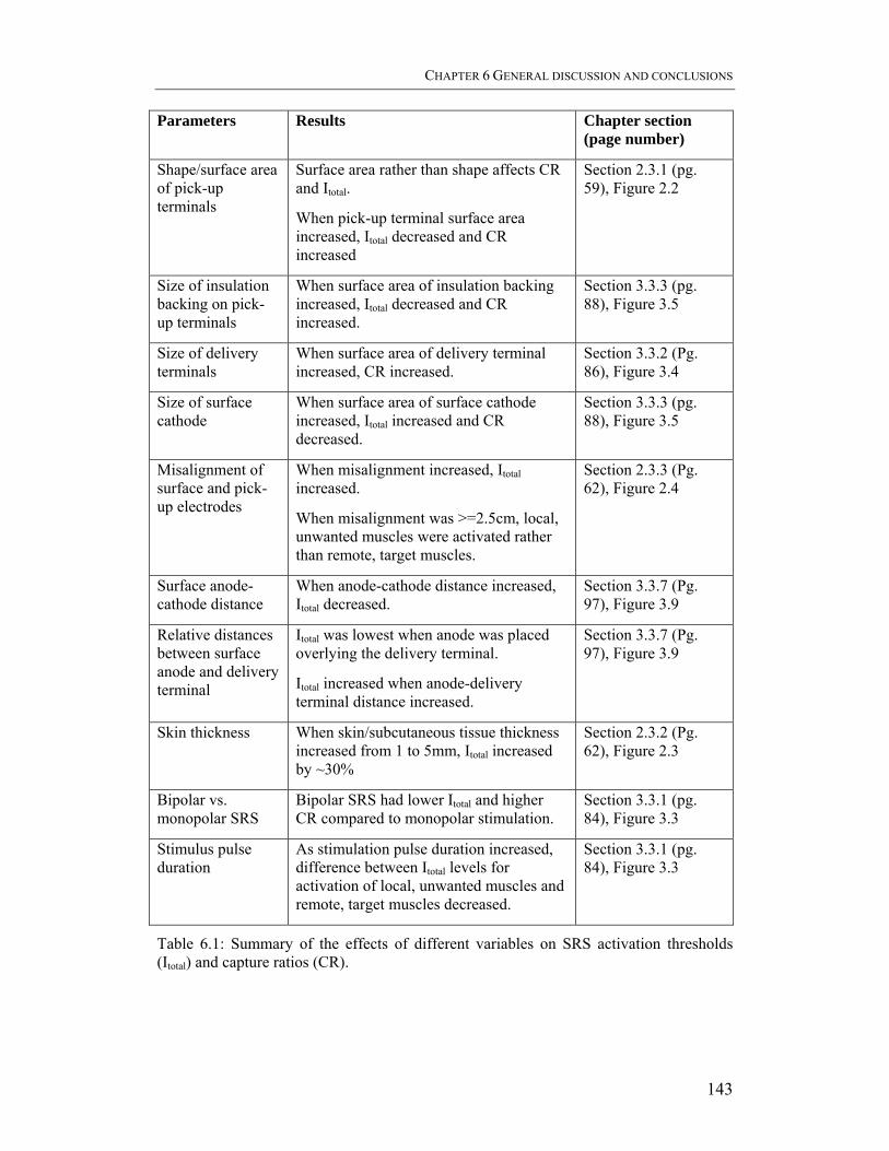
CHAPTER 6 GENERAL DISCUSSION AND CONCLUSIONS
Parameters Results Chapter section (page number)
Shape/surface area of pick-up terminals
Surface area rather than shape affects CR and Itotal.
When pick-up terminal surface area increased, Itotal decreased and CR increased
Section 2.3.1 (pg. 59), Figure 2.2
Size of insulation backing on pick-up terminals
When surface area of insulation backing increased, Itotal decreased and CR increased.
Section 3.3.3 (pg. 88), Figure 3.5
Size of delivery terminals
When surface area of delivery terminal increased, CR increased.
Section 3.3.2 (Pg. 86), Figure 3.4
Size of surface cathode
When surface area of surface cathode increased, Itotal increased and CR decreased.
Section 3.3.3 (pg. 88), Figure 3.5
Misalignment of surface and pick-up electrodes
When misalignment increased, Itotal increased.
When misalignment was >=2.5cm, local, unwanted muscles were activated rather than remote, target muscles.
Section 2.3.3 (Pg. 62), Figure 2.4
Surface anode-cathode distance
When anode-cathode distance increased, Itotal decreased.
Section 3.3.7 (Pg. 97), Figure 3.9
Relative distances between surface anode and delivery terminal
Itotal was lowest when anode was placed overlying the delivery terminal.
Itotal increased when anode-delivery terminal distance increased.
Section 3.3.7 (Pg. 97), Figure 3.9
Skin thickness When skin/subcutaneous tissue thickness increased from 1 to 5mm, Itotal increased by ~30%
Section 2.3.2 (Pg. 62), Figure 2.3
Bipolar vs. monopolar SRS
Bipolar SRS had lower Itotal and higher CR compared to monopolar stimulation.
Section 3.3.1 (pg. 84), Figure 3.3
Stimulus pulse duration
As stimulation pulse duration increased, difference between Itotal levels for activation of local, unwanted muscles and remote, target muscles decreased.
Section 3.3.1 (pg. 84), Figure 3.3
Table 6.1: Summary of the effects of different variables on SRS activation thresholds (Itotal) and capture ratios (CR).
143
CHAPTER 6 GENERAL DISCUSSION AND CONCLUSIONS
Lastly, it was understood that the success of an NP depended heavily on
user acceptance. A participant will continue to use a NP device only if the benefit
from it outweighs the costs. The benefit is measured in functional gain, while the
costs include mental, emotional and physical aggravation as well as financial
costs. In the first human pilot study described in Chapter 5, the subject was
satisfied with the system and found it to be useful in performing daily activities.
The subject also described the SRS to be more comfortable than the conventional
surface NP that he was familiarized with prior to the implantation. The subject
continues to use the device daily despite the need to don and doff the external
garment. The results indicated that SRS will likely be accepted as a long term NP
as long as it remains reliable and useful.
Equivalent circuit model
The SRS in its simplest monopolar form can be represented by the
equivalent circuit model shown in Figure 6.1. Ze, represents the impedance at the
surface electrode - skin interface. The skin impedance is modeled with a parallel
RC circuit, with Cs and Rs representing the skin capacitance and resistance
respectively. Much of the skin capacitance has been shown to lie in the stratum
corneum, the outermost layer of the epidermis made out of dead skin cells (Reilly
1992). If the corneum is stripped away either through abrasion or extensive skin
preparation, the skin capacitance decreases to a small fraction of its intact value.
In the experiments described in this thesis, the skin resistance likely depended on
both the stratum cornuem and the underlying skin layers. With intact skin, Rs was
found to vary significantly with applied voltage, whereas when the stratum
corneum was removed, Rs remained independent of stimulus level. Rsub represents
the resistance of the relatively conductive subcutaneous tissues. In our
experiments it depended on both surface electrode area and separation. In the
subcutaneous tissues underlying the surface electrodes, current spreads through a
hemispherical volume. In our experiments the resistance was inversely related to
surface electrode area. At the point where current no longer spread out with
144
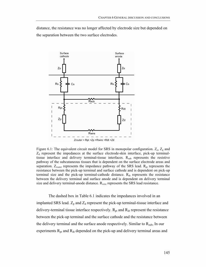
CHAPTER 6 GENERAL DISCUSSION AND CONCLUSIONS
distance, the resistance was no longer affected by electrode size but depended on
the separation between the two surface electrodes.
Figure 6.1: The equivalent circuit model for SRS in monopolar configuration. Ze, Zp and Zd represent the impedances at the surface electrode-skin interface, pick-up terminal-tissue interface and delivery terminal-tissue interfaces. Rsub represents the resistive pathway of the subcutaneous tissues that is dependent on the surface electrode areas and separation. Zrouter represents the impedance pathway of the SRS lead. Rpt represents the resistance between the pick-up terminal and surface cathode and is dependent on pick-up terminal size and the pick-up terminal-cathode distance. Rdt represents the resistance between the delivery terminal and surface anode and is dependent on delivery terminal size and delivery terminal-anode distance. Rwire represents the SRS lead resistance.
The dashed box in Table 6.1 indicates the impedances involved in an
implanted SRS lead. Zp and Zd represent the pick-up terminal-tissue interface and
delivery-terminal tissue interface respectively. Rpt and Rdt represent the resistance
between the pick-up terminal and the surface cathode and the resistance between
the delivery terminal and the surface anode respectively. Similar to Rsub, In our
experiments Rpt and Rdt depended on the pick-up and delivery terminal areas and
145
CHAPTER 6 GENERAL DISCUSSION AND CONCLUSIONS
the cathode-pick-up terminal and anode-delivery terminal distances. The
resistance of the SRS lead is represented by Rwire.
It is apparent from the equivalent circuit model that the capture ratio of an
SRS lead depends on the relative values of Rsub and Zrouter. A capture ratio of 10%
implies that Rsub is approximately 1/10 of Zrouter. Rpt and Rdt increase as the size of
the pick-up and delivery terminals decrease, resulting in lower Zrouter and hence
higher capture ratio. On the other hand, increasing the size of the surface
electrodes decreases Rsub and less current flows through the SRS lead. The effects
of different parameters on SRS capture ratios (as shown in Table 6.1) can be
addressed using the model and are summarized in Table 6.2. In Chapter 3, it was
shown that capture ratios were higher in the bipolar SRS than in the monopolar
configuration. With the target nerve lying within the muscles, Rdt likely had a
higher value compared to the sum of Zp, Zd, Rpt and Rwire. Hence, in the case of a
bipolar SRS, Zrouter = 2*(Rpt+Zp+Rwire+Zd) has a lower impedance than in a
monopolar SRS, where Zrouter = Rpt+Zp+Rwire+Zd+Rdt, resulting in higher capture
ratios.
146
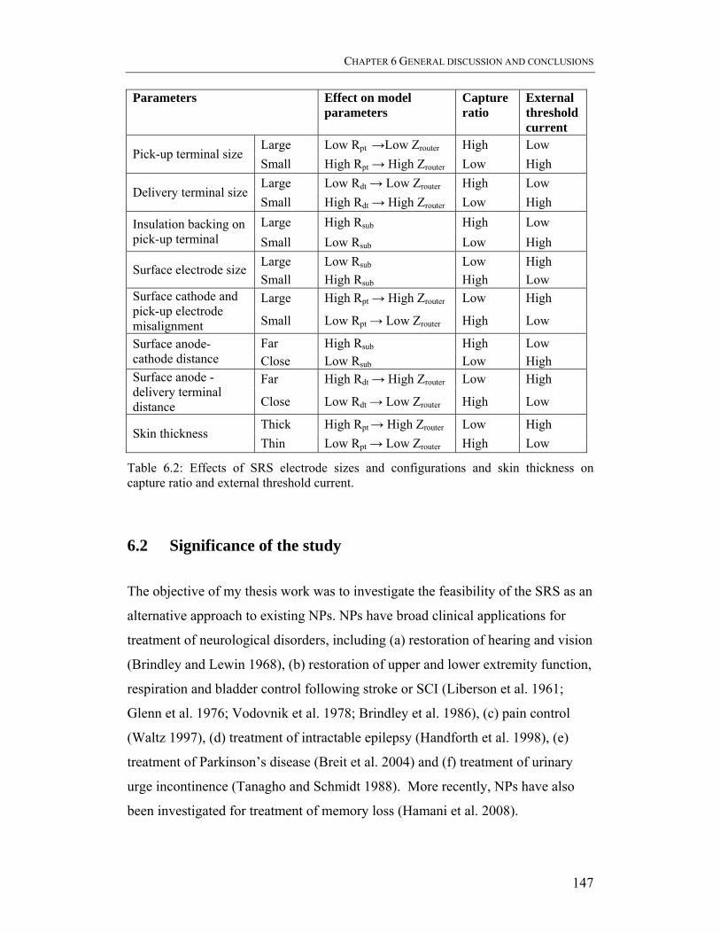
CHAPTER 6 GENERAL DISCUSSION AND CONCLUSIONS
Parameters Effect on model parameters
Capture ratio
External threshold current
Large Low Rpt →Low Zrouter High Low Pick-up terminal size
Small High Rpt → High Zrouter Low High Large Low Rdt → Low Zrouter High Low
Delivery terminal size Small High Rdt → High Zrouter Low High Large High Rsub High Low Insulation backing on
pick-up terminal Small Low Rsub Low High Large Low Rsub Low High Surface electrode size Small High Rsub High Low Large High Rpt → High Zrouter Low High Surface cathode and
pick-up electrode misalignment Small Low Rpt → Low Zrouter High Low
Far High Rsub High Low Surface anode-cathode distance Close Low Rsub Low High
Far High Rdt → High Zrouter Low High Surface anode - delivery terminal distance Close Low Rdt → Low Zrouter High Low
Thick High Rpt → High Zrouter Low High Skin thickness
Thin Low Rpt → Low Zrouter High Low
Table 6.2: Effects of SRS electrode sizes and configurations and skin thickness on capture ratio and external threshold current.
6.2 Significance of the study
The objective of my thesis work was to investigate the feasibility of the SRS as an
alternative approach to existing NPs. NPs have broad clinical applications for
treatment of neurological disorders, including (a) restoration of hearing and vision
(Brindley and Lewin 1968), (b) restoration of upper and lower extremity function,
respiration and bladder control following stroke or SCI (Liberson et al. 1961;
Glenn et al. 1976; Vodovnik et al. 1978; Brindley et al. 1986), (c) pain control
(Waltz 1997), (d) treatment of intractable epilepsy (Handforth et al. 1998), (e)
treatment of Parkinson’s disease (Breit et al. 2004) and (f) treatment of urinary
urge incontinence (Tanagho and Schmidt 1988). More recently, NPs have also
been investigated for treatment of memory loss (Hamani et al. 2008).
147
CHAPTER 6 GENERAL DISCUSSION AND CONCLUSIONS
Apart from miniaturization and improvements in the electronics, the basic
operational design of NPs has remained relatively unchanged over the last 4
decades. Existing NP configurations are either surface, percutaneous or implanted
systems, which have existed since the 1960s. Many of the implanted NPs today
are based on the radio frequency coupled stimulator developed by Glenn et al. in
1958 for cardiac pacing (McNeal 1977). The main disadvantage of these
conventional systems is cost, and the need to surgically implant a hermetically
sealed container of electronic components. The containers can be relatively
bulky, particularly when intended for the forearm or leg (e.g. the STIMuGRIP
(Spensley 2007)). If the containers are implanted in the chest wall, long leads are
required to be pulled subcutaneously across joints to the target muscles or nerves.
The implanted stimulators require external components such as external coils and
control units, to deliver power and/or command signals to the implanted
stimulator. Advancement in electronic technology has allowed for improved
functionality and further miniaturization of the implanted stimulators over the
years. The state of the art of these stimulators is the BION, which greatly reduced
the invasiveness and costs associated with surgically implanted NPs (Loeb et al.
2001; Burridge and Etherington 2004; Weber et al. 2004; Loeb et al. 2006).
However, due to its small size, the coupling coefficient for power and command
signal delivery is limited. Placement of external coils can be difficult as the
locations of BIONs become more distributed. Although BIONs with rechargeable
batteries may allow a single external coil to communicate over relatively long
distances with several implanted BIONs, the high power demand in motor
applications might require frequent recharging.
In parallel to the development of implanted NPs, Liberson’s invention of a
non-invasive, heel- switch-triggered stimulator for foot drop correction in 1961
provided the blueprint for surface NPs in the years to come (McNeal 1977). The
disadvantages of surface systems include inadequate selectivity and reliability.
Donning and doffing can be daunting in patients with physical disabilities.
Stimulation through the skin at the levels required to activate the targeted muscles
148
CHAPTER 6 GENERAL DISCUSSION AND CONCLUSIONS
can cause discomfort. However, these systems remained attractive since they are
non-invasive and relatively inexpensive.
The SRS is arguably the first fundamentally different approach to NPs
since 1960s. The system has several advantages compared to existing NPs.
Greater selectivity is achieved compared to conventional surface stimulation
because current is routed to deep-lying nerves through the implanted leads. Unlike
surface NPs, where electrodes must be placed over motor points, which may be
widely distributed and in inconvenient locations, several SRS leads can be routed
subcutaneously to a convenient location. As a result, the external garments
containing the surface electrodes and stimulator are much smaller, easier to don
and doff, more comfortable and attract less attention. Without an implanted
stimulator, the surgical procedure is shorter and less invasive, reducing surgical
costs, risk of infection and recovery. It also eliminates the need for implanted
leads to be tunneled across joints to the site of the implanted stimulator, therefore
reducing trauma and the chances of lead failures in long term. Lastly, the price of
an SRS system will likely be lower than an implanted system due to lower
developmental cost.
However, as a ‘hybrid’ system that capitalizes on the advantages of
existing NPs, the SRS it also retains some of their disadvantages. The
implantation of the SRS leads in this study still required open surgery.
Hospitalization, surgical and recovery costs can impose unwanted psychological
and financial burden for subjects. The SRS surface electrodes must make good
electrical contact with the skin and this can be a drawback compared to inductive
coupling. Donning and doffing of the external garments containing the surface
electrodes may be less convenient than attaching an external coil to the skin. Also,
the SRS is limited in the number of individual stimulation channels that can be
provided, since each additional lead requires a surface electrode occupying a
minimum of 7cm2 of skin surface. Hence, in applications that require more than
four channels a fully implanted NP may remain the device of the choice.
149
CHAPTER 6 GENERAL DISCUSSION AND CONCLUSIONS
6.3 Future directions
6.3.1 Safety and MRI compatibility
Nerve cuff electrodes have been shown to be safe as long as proper
precautions were taken during the implantation procedure to avoid compression of
the nerve trunks (Mortimer and Bhadra 2004). In 2 animals that were chronically
implanted with SRS leads described in Chapter 5, no motor function deficit was
observed over the course of the implantation, which lasted over 15 months. In
post-mortem dissections, encapsulation tissue was noted within and around the
implanted nerve cuffs. No tissue erosion was noted on visual inspection.
However, histological studies should be conducted to further address the long
term effects of the SRS delivery terminals on target nerves. Also, MRI
compatibility of the SRS leads should be tested and determined before the
commencement of a full clinical trial.
6.3.2 Further optimization of current SRS configurations
Most of the efforts in optimizing the SRS so far have focused on
minimizing the amount of surface current needed to activate the target nerve. The
system can also be improved by increasing the comfort of the external garment or
by increasing the ease of daily donning and doffing. One possible approach is to
reduce the size of the external garment by eliminating the common indifferent
electrode. Currently, each surface stimulating electrode overlies a pick-up
terminal of an implanted lead and there is a common indifferent electrode about
10 cm away. We have found that the indifferent electrode can be eliminated if a
given surface electrode serves either as a stimulating electrode or as an indifferent
electrode. This can be achieved by reversing the polarities of the phases of the
pulses between pairs of electrodes overlying pick-up terminals so that when an
electrode acts to stimulate, it delivers a negative-phase-first pulse and when it
serves as the indifferent, it delivers a positive-phase-first pulse. The duration of
150
CHAPTER 6 GENERAL DISCUSSION AND CONCLUSIONS
the secondary phase must be increased and its amplitude reduced to avoid
activation by the electrode acting as the indifferent, while still maintaining charge
balance. Because pairs of surface electrodes may now be in closer proximity to
each other, activation thresholds may increase (Chapter 3). This might result in
activation of the cutaneous sensory fibres underlying the surface electrodes. Also,
the stimulation waveform should be tested to ensure that electrode corrosion and
tissue damage will not occur as a result of the longer duration secondary phase, as
the electrochemical processes resulting from the charge injected in the primary
phase might not be completely reversed. If this method proves to be safe, the
elimination of the indifferent electrode in the external garment for a 3-channel
system (as in the case of the first human pilot study) could potentially reduce the
size of the garment and external stimulator to that of a wrist watch. Donning and
doffing of such a device would then be more convenient, than the attachment of
an inductive coil and associated electronics.
6.3.3 Minimally invasive implantation techniques
The delivery terminal of the SRS leads currently consists of a nerve cuff
electrode which has to be implanted during cut-down surgery that exposes the
target nerve. The costs of the SRS system would be greatly reduced if open
surgeries could be avoided for SRS lead implantation. One possible alternative to
existing SRS lead design is to use an intramuscular electrode as the delivery
terminal to allow for percutaneous implantation of the SRS leads through biopsy
needles. However, the amount of surface current needed to activate the target
nerves would increase due to the increase in current shunting at the delivery
terminal and the increased separation of the target nerve and the delivery terminal.
From previous experience, this would likely result in co-activation of local motor
or sensory fibres under the surface electrodes before the full range of target
muscle contractions are achieved. Hence, this approach might be more suitable
for applications that require only low stimulation amplitudes, such as those
employed in certain neuromodulation applications. An alternative approach is to
151
CHAPTER 6 GENERAL DISCUSSION AND CONCLUSIONS
utilize endoscopes to allow for implantation of the current SRS leads through
minimally invasive surgical procedures. Depending on the application and the
location of the target nerve, this approach might significantly minimize the
amount of trauma and recovery time, hence maximizing the potential of the SRS
as an alternative NP to complement existing systems.
6.3.4 Clinical applications
The SRS potentially has a wide range of clinical applications. The
feasibility of the SRS for bladder control using high-frequency stimulation of the
pudendal nerves for inhibition of the urethral sphincter has been shown in
anaesthetized animals (Gaunt and Prochazka 2009). The application of the SRS
for pain control is also being investigated by Bioness Inc., a biomedical company
in the United States. Animal studies are underway in my supervisor’s laboratory
to investigate the feasibility of the system for the treatment of spasticity. Future
studies are planned to explore other clinical applications. As stated previously, the
SRS is probably most suitable for applications that require 4 channels or less.
Examples of these applications include stimulation for foot-drop, diaphragm
pacing, vagal nerve stimulation and inhibiting urinary urge incontinence.
6.4 Concluding remarks
Despite the advancement in CNS regeneration, a biological “cure” that
will reverse neurological damage or loss due to stroke or SCI remains elusive.
NPs on the other hand, can already provide clear benefits in many disabilities
resulting from neurological damage. Hence, it is expected that the need for NP
development and application will continue to increase in the foreseeable future. It
is hoped that the SRS will be a useful addition to the field, and that the work
described in this thesis will have played a role in establishing the basics of
operation and the proof of principle of this new approach.
152

CHAPTER 6 GENERAL DISCUSSION AND CONCLUSIONS
6.5 References
Breit S, Schulz JB, and Benabid AL. Deep brain stimulation. Cell Tissue Res 318: 275-288, 2004.
Brindley GS, and Lewin WS. The sensations produced by electrical stimulation of the visual cortex. J Physiol 196: 479-493, 1968.
Brindley GS, Polkey CE, Rushton DN, and Cardozo L. Sacral anterior root stimulators for bladder control in paraplegia: the first 50 cases. J Neurol Neurosurg Psychiatry 49: 1104-1114, 1986.
Burridge J, and Etherington R. A Preliminary Clinical Study using RF BION®1 Microstimulators to Facilitate Upper Limb Function in Hemiplegia. Advances in Clinical Neuroscience and Rehabilitation 4: 26-27, 2004.
Gaunt RA, and Prochazka A. Transcutaneously coupled, high-frequency electrical
stimulation of the pudendal nerve blocks external urethral sphincter contractions. Neurorehabil Neural Repair 23: 615-626, 2009.
Glenn WW, Holcomb WG, Shaw RK, Hogan JF, and Holschuh KR. Long-term ventilatory support by diaphragm pacing in quadriplegia. Ann Surg 183: 566-577, 1976.
Grill WM, and Mortimer JT. Stability of the input-output properties of chronically implanted multiple contact nerve cuff stimulating electrodes. IEEE Trans Rehabil Eng 6: 364-373, 1998.
Hamani C, McAndrews MP, Cohn M, Oh M, Zumsteg D, et al. Memory enhancement induced by hypothalamic/fornix deep brain stimulation. Ann Neurol 63: 119-123, 2008.
Handforth A, DeGiorgio CM, Schachter SC, Uthman BM, Naritoku DK, et al. Vagus nerve stimulation therapy for partial-onset seizures: a randomized active-control trial. Neurology 51: 48-55, 1998.
Liberson WT, Holmquest HJ, Scot D, and Dow M. Functional electrotherapy: stimulation of the peroneal nerve synchronized with the swing phase of the gait of hemiplegic patients. Arch Phys Med Rehabil 42: 101-105, 1961.
Loeb GE, Peck RA, Moore WH, and Hood K. BION system for distributed neural prosthetic interfaces. Med Eng Phys 23: 9-18, 2001.
Loeb GE, Richmond FJ, and Baker LL. The BION devices: injectable interfaces with peripheral nerves and muscles. Neurosurg Focus 20: E2, 2006.
153
CHAPTER 6 GENERAL DISCUSSION AND CONCLUSIONS
McNeal DR. 2000 years of electrical stimulation. In: Functional electrical stimulation: applications in neural prostheses, edited by Hambrecht FT, and Reswick JB. New York: Marcel Dekker, Inc., 1977, p. 3-36.
Mortimer JT, and Bhadra N. Peripheral nerve and muscle stimulation. In: Neuroprosthetics: Theory and Practice, edited by Horch KW, and Dhillon GS. Singapore: World Scientific Publishing Co. Pte. Ltd., 2004, p. 639-682.
Reilly J. Electrical stimulation and electropathology. Cambridge: Cambridge University Press, 1992.
Spensley J. STIMuGRIP; a new hand control implant. Conf Proc IEEE Eng Med Biol Soc 2007: 513, 2007.
Tanagho EA, and Schmidt RA. Electrical stimulation in the clinical management of the neurogenic bladder. J Urol 140: 1331-1339, 1988.
Vodovnik L, Kralj A, Stanic U, Acimovic R, and Gros N. Recent applications of functional electrical stimulation to stroke patients in Ljubljana. Clin Orthop Relat Res 64-70, 1978.
Waltz JM. Spinal cord stimulation: a quarter century of development and investigation. A review of its development and effectiveness in 1,336 cases. Stereotact Funct Neurosurg 69: 288-299, 1997.
Weber DJ, Stein RB, Chan KM, Loeb GE, Richmond FJ, et al. BIONic WalkAide for correcting foot drop. Conf Proc IEEE Eng Med Biol Soc 6: 4189-4192, 2004.
154

![INDEX [microdentsystem.com] · INTRODUCTION REMOVABLE AND IMMEDIATE . PROSTHESIS MULTIPLE PROSTHESIS. CEMENTED PROSTHESIS. Microdent Genius conical (straight) abutment or Microdent](https://img.pdfslide.us/doc/110x75/5facd9ef77a5ed547a36b19e/index-introduction-removable-and-immediate-prosthesis-multiple-prosthesis.jpg)
![INDEX [microdentsystem.com] · 2015-11-24 · INDEX PRESENTATION. INTRODUCTION MULTIPLE PROSTHESIS. REMOVABLE AND IMMEDIATE PROSTHESIS. SINGLE PROSTHESIS CEMENTED PROSTHESIS. Microdent](https://img.pdfslide.us/doc/110x75/5facd9ee77a5ed547a36b19c/index-2015-11-24-index-presentation-introduction-multiple-prosthesis-removable.jpg)