Embed Size (px)
Citation preview
THE SOUND ENGINEERING MAGAZINE
MAY 1972 $1.00
www.americanradiohistory.com
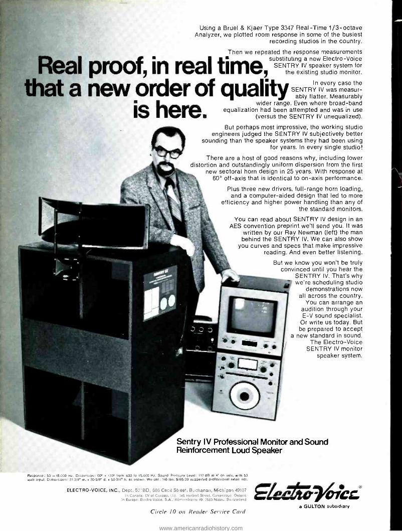
Using a Bruel & Kjaer Type 3347 Real -Time 1/3- octave Analyzer, we plotted room response in some of the busiest
recording studios in the country.
Then we repeated the response measurements substituting a new Electro -Voice
SENTRY IV speaker system for the existing studio monitor. Real proof in real ti 9 ...
that a new order of quality In every case the SENTRY IV was measur-
ably flatter. Measurably
ishere. wider range. Even where broad -band
equalization had been attempted and was in use (versus the SENTRY IV unequalized).
But perhaps most impressive, the working studio engineers judged the SENTRY IV subjectively better
sounding than the speaker systems they had been using for years. In every single studio!
There are a host of good reasons why, including lower distortion and outstandingly uniform dispersion from the first
new sectoral horn design in 25 years. With response at 60° off -axis that is identical to on -axis performance.
Plus three new drivers, full -range horn loading, and a computer -aided design that led to more
efficiency and higher power handling than any of the standard monitors.
You can read about SENTRY IV design in an AES convention preprint we'll send you. It was
written by our Ray Newman (left) the man behind the SENTRY IV. We can also show
you curves and specs that make impressive reading. And even better listening.
But we know you won't be truly convinced until you hear the
SENTRY IV. That's why were scheduling studio
demonstrations now all across the country.
You can arrange an audition through your E -V sound specialist.
Or write us today. But be prepared to accept
a new standard in sound. The Electro -Voice
SENTRY IV monitor speaker system.
Sentry IV Professional Monitor and Sound Reinforcement Loud Speaker
Response: 50- 18,000 Hz. Dispersion: 60° n 120' from 600 to 15.000 Hz. Sound Pressure Level: 117 dB at 4' on axis, with 50 waft input. Dimensions: 273/4° w. a 20.5/8° d. x 503/4 h. as shown. Welph1: 148 lOs. $495.00 suggested professional retail net.
ELECTRO- VOICE, INC., Dept. 521BD, 686 Cecil Street, Buchanan, Michigan 49107 In Canada EV of Canada, Ltd. 345 Herbert Street, Gananoque, Onlar.o
In Europe: Elcctro.Voiee, S.A., Römerslrasso 49. 2560 Nidau, Switzerland
Circle 10 on Reader Service Card a GULTON subsidiary
www.americanradiohistory.com
COMING NEXT MONTH
A special issue -devoted to four - channel sound and recording. This im- portant topic will be discussed from a variety of viewpoints as we do a de- tailed wrap up of the recent Midwest Acoustics Conference. This Confer- ence spent a complete day in ex- plaining, detailing, and discussing four - channel recording techniques, available and coming hardware, and trends that are appearing. You will get an up -to- the minute concept of just what the four -channel scene is all about from this article.
An oscilloscope display that shows the four -channel output of a system is a real boon to the recording engineer. Donald L. Patten has developed a black box that will convert a conven- tional 'scope into a four -channel dis- play 'scope. He tells you how to build it. And with it there will be no excuse for wrong phase information in any channel, unless you want it there.
Stephen H. Lampen of 3P Record- ing returns to our pages as he de- scribes how he used portable profes- sional four -channel recording equip- ment to record live theater.
And there will be our regular col- umnists: George Alexandrovich, Nor- man H. Crowhurst, Martin Dickstein, and John Woram. Coming in db, The Sound Engineering Magazine.
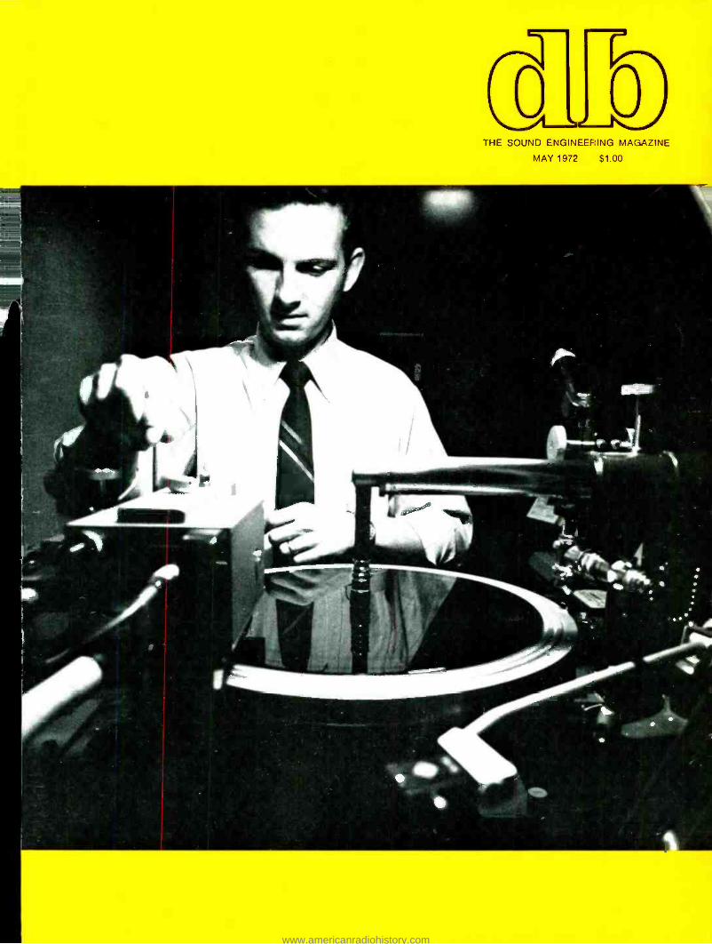
ABOUT THE COVER
In the end, the tapes made by re- cording studios must come to the disc mastering room. This is the last audio controllable action that will be taken before the ultimate user gets his copy.
18
24
26
2
'0 r
3 THE SOUND ENGINEERING MAGAZINE
MAY 1972 VOLUME 6, NUMBER 5
THE DIGITAL DELAY LINE Richard Factor and Stephen Katz
A TRANSMITTER CONTROL PANEL Ellwood W. Lippencott
AUTOMATING THE AUDIO CONTROL FUNCTION, PART 2 Walter Jung
THE AUDIO ENGINEER'S HANDBOOK George Alexandrovich
10 THE SYNC TRACK John Woram
14 THEORY AND PRACTICE Norman H. Crowhurst
16 NEW PRODUCTS AND SERVICES
17 A NOTE FROM THE PUBLISHER
34 SOUND WITH IMAGES Martin Dickstein
36 BOOKCASE
37 CLASSIFIED
38 PEOPLE, PLACES, HAPPENINGS
db is listed in Current Contents: Engineering and Technolo} ),
Robert Bach PUBLISHER
Bob Laurie ART DIRECTOR
A. F. Gordon CIRCULATION MANAGER
Eloise Beach ASST. CIRCULATION MGR.
Larry Zide EDITOR John Woram ASSOCIATE EDITOR Marilyn Gold COPY EDITOR
Richard L. Lerner ASSISTANT EDITOR
GRAPHICS Crescent Art Service
db. the Sound Engineering Magazine is published monthly by Sagamore Publishing Company. Inc. Entire contents copyright © 1972 by Sagamore Publishing Co.. Inc.. 980 Old Country Road. Plainview, L.I.. N.Y. 11803. Telephone (516) 433 6530. db is published for those individuals and firms in professional audio - recording, broadcast. audio -visual. sound reinforcement. consultants. video recording, film sound. etc. Appli- cation should be made on the subscription form in the rear of each issue. Subscriptions are $6.00 per year ($7.00 per year outside U. S. Possessions. Canada. and Mexico) in U. S. funds. Single copies are $1.00 each. Controlled Circulation postage paid at Harrisburg. Pa. 17105. Editorial. Publishing, and Sales Offices: 980 Old Country Road. Plainview. New York 11803. Postmaster: Form 3579 should be sent to above address.
www.americanradiohistory.com
George Alexandrovich
THE AUDIO ENGINEER'S HANDBOOK
Resistive Pads-the Practical Way
Since most pads used today are home brewed it seems appropriate to review the most commonly used types so as to design them easily without sacrificing accuracy. Pads are used for many different purposes: iso- lation, matching of impedances and levels, termination, combining, and splitting.
In practice there are two types of circuits to be concerned with -bal- anced and unbalanced. Before we get to the design of the pads we have to define the purpose of the pad we are to construct. Most likely we are con- fronted with two circuits which are to be joined or interconnected. In the video field most of the circuits are of standard impedance and level and can be readily interconnected. Audio cir- cuits are tricky most of the times. Aside from the fact that many trans- former- isolated circuits require correct termination, the output from such a circuit can be permanently delegated into one line while part of the signal is diverted through switching into other circuits. Any change in loading of the source impedance will affect the level of the distributed signal. Many pro- fessional institutions prefer to perman- ently terminate the circuit and bridge - off with much higher impedance lines. Usually bridging means acquiring the signal by connecting the load of at least ten times larger than the source impedance. Actually, in all present - day transistorized class AB amplifiers with very low output impedances, we are bridging loads. That is why the output level of the amplifier remains
cu constant.
Let's get back to the question of the pad. What do we want the pad to do? For one thing, should it or shouldn't it terminate the source? Secondly should it change the signal level? Third, should it present the load with the proper terminating impedance?
Let us talk first about unbalanced circuits. Several types of pads can be used. The simplest is the bridging re- sistor. It is a simplified form of voltage divider pad where the shunt element
advertisers index Allison Research Altec Ampex Auditronics Duncan Electronics Electro -Voice
29 5
Cover 4 29
7 Cover 2
Fairchild Sound 19, 20 Gately Electronics 16 Gotham Audio 4, 15 Gray Research 14
Infonics 33 KMK 15
Koss facing cover 2 Miller -Stephenson 13 Nortronics 6 Olive 13 Pentagon 30 ReVox 3 Sony Corp. 9 Stanton Magnetics 10 Timekeeper 8, 12 UREI 11, 14
THE SOUND ENGINEERING MAGAZINE
SALES OFFICES
New York 980 Old Country Road Plainview, N.Y. 11803
516- 433 -6530
Dallas Roy McDonald Associates, Inc.
Semmons Tower West Suite 714
Dallas, Texas 75207 214 -637 -2444
Denver Roy McDonald Associates, Inc.
846 Lincoln Street Denver, Colorado 80203
303 -825 -3325
Houston Roy McDonald Associates, Inc.
3130 Southwest Freeway Houston, Texas 77006
713 -529 -6711
Los Angeles Roy McDonald Associates, Inc.
1313 West 8th Street Los Angeles, California 90018
213- 483 -1304
Portland Roy McDonald Associates, Inc.
2305 S. W. 58th Avenue Portland, Oregon 97221
503 -292 -8521
San Francisco Roy McDonald Associates, Inc.
625 Market Street San Francisco, California 94105
415- 397 -5377
www.americanradiohistory.com
The Quietest Revox
One of the most compelling reasons for buying a Revox is the sounds it doesn't make.
No spurious pops or clicks. No wavering, fluttering tones. No distracting hum. And best of all, virtually noise -free electronics.
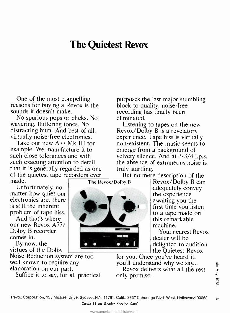
Take our new A77 Mk III for example. We manufacture it to such close tolerances and with such exacting attention to detail, that it is generally regarded as one of the quietest tape recorders ever made.
Unfortunately, no matter how quiet our electronics are, there is still the inherent problem of tape hiss.
And that's where our new Revox A77/ Dolby B recorder comes in.
By now, the virtues of the Dolby Noise Reduction system are well known to require any elaboration on our part.
Suffice it to say, for all practical
purposes the last major stumbling block to quality, noise -free recording has finally been eliminated.
Listening to tapes on the new Revox /Dolby B is a revelatory experience. Tape hiss is virtually non -existent. The music seems to emerge from a background of velvety silence. And at 3 -3/4 i.p.s. the absence of extraneous noise is truly startling.
But no mere description of the Revox /Dolby B can adequately convey the experience awaiting you the first time you listen to a tape made on this remarkable machine.
Your nearest Revox dealer will be delighted to audition the Quietest Revox
for you. Once you've heard it, you'll understand why we say...
Revox delivers what all the rest only promise.
The Revox /Dolby B
too
Revox Corporation, 155 Michael Drive, Syosset, N.Y. 11791. Calif.: 3637 Cahuenga Blvd. West, Hollywood 90068 w
Circle 11 on Reader Service Card
www.americanradiohistory.com
ALL ELECTRONIC DIGITAL AUDIO DELAY SYSTEM Five Independent Outputs
Each Output Separately Adjustable in 5 ms Steps From 5 -320 ms
The Delta -T101 is an audio recorder and play-
back unit which uses neither tape nor moving parts. It converts audio into a digital code and
stores it in its computer solid -state memory. It can therefore offer you the following specifi- cations:
zero wow and flutter +22 dBM output with less than 1% dis- tortion 60 dB dynamic range frequency response 20 -12kHz ±2 dB
standard 19" rack panel, 7" high and 18" behind the panel
In one stroke, the DeltaT 101 eliminates all the problems of tape delay: no mechanical failure, no wow and flutter, no drop -outs or broken loops, no tape hiss or distortion. You can
plug it into your rack, set it, and forget it. When the Delta -T 101 was being designed,
we had two options: 1) Make a unit with all the flexibility demanded
by the job; 2) Cut costs to the bone and let the "concept"
sell the unit. We took the first course. Sure, fixed delays
would have been cheaper, but we know from experience that you never know exactly how much delay you will need until you make the installation. And even in fixed installations it becomes necessary to change delays to suit the speaker set -up required by a particular program. We made the steps 5 ms, because this is the smallest increment ever needed.
For additional information, call or write:
GOTH M AUDIO CORPORATION
2 west 46th Street, New York, NY 10036 (212) 2654111 . 1710 N. La Brea Menue, Hollyeoed, CA 90046 (213) 874-4444
Circle 13 on Reader Service Card
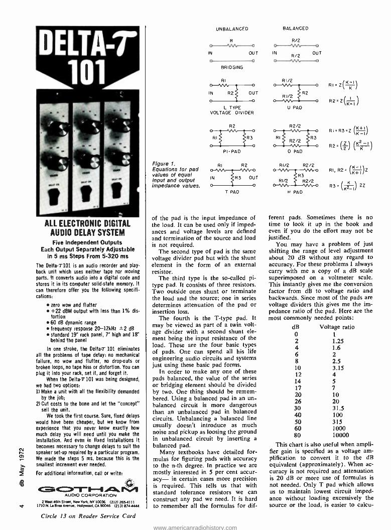
Figure 1. Equations for pad values of equal input and output impedance values.
UNBALANCED
R p W o
IN OUT
o 0
BRIDGING
RI
IN R2 OUT
L TYPE VOLTAGE DIVIDER
R2
RI R3.
PI-PAD
RI R2
IN R3 OUT
T PAD
of the pad is the input impedance of the load. It can be used only if imped- ances and voltage levels are defined and termination of the source and load is not required.
The second type of pad is the same voltage divider pad but with the shunt element in the form of an external resistor.
The third type is the so- called pi- type pad. It consists of three resistors. Two outside ones shunt or terminate the load and the source; one in series determines attenuation of the pad or insertion loss.
The fourth is the T -type pad. It may be viewed as part of a twin volt- age divider with a second shunt ele- ment being the input resistance of the load. These are the four basic types of pads. One can spend all his life engineering audio circuits and systems just using these basic pad forms.
In order to make any one of these pads balanced, the value of the series or bridging element should be divided by two. One thing should be remem- bered. Using a balanced pad in an un- balanced circuit is more dangerous than an unbalanced pad in balanced circuits. Unbalancing a balanced line usually doesn't introduce as much noise and pickup as loosing the ground in unbalanced circuit by inserting a balanced pad.
Many textbooks have detailed for- mulas for figuring pads with accuracy to the n -th degree. In practice we are mostly interested in 5 per cent accur- acy- in certain cases more precision is required. This tells us that with standard tolerance resistors we can construct any pad we need. It is hard to remember all the formulas for dif-
BALANCED
R/2
IN OUT o--- RI/2
U PAD
R2/2
RI R3
O PAD
RI/2 R2/2
R3 RI/2 R2/2
H PAD
RI=Z(K1\ /
R2. Z( ) K-I
RI=R3=Z (K+I\ K-I/
R2'(2/ l¡ ll (KK_I/
RI, 82' (K+I/Z
R3= (K) 2Z
ferent pads. Sometimes there is no time to look it up in the book and even if you do the effort may not be justified.
You may have a problem of just shifting the range of level adjustment about 20 dB without any regard to accuracy. For these problems I always carry with me a copy of a dB scale superimposed on a voltmeter scale. This instantly gives me the conversion factor from dB to voltage ratio and backwards. Since most of the pads are voltage dividers this gives me the im- pedance ratio of the pad. Here are the most commonly needed points:
dB Voltage ratio 0 1
2 1.25 4 1.6 6 2 8 2.5 10 3.15 12 4 14 5 17 7 20 10 26 20 30 31.5 40 100 50 315 60 1000 80 10000
This chart is also useful when ampli- fier gain is specified as a voltage am- plification to convert it to the dB equivalent (approximately). When ac- curacy is not required and attenuation is 20 dB or more use of formulas is
not needed. Only T pad which allows us to maintain lowest circuit imped- ance without loading excessively the source or the load, is easier to calcu-
www.americanradiohistory.com
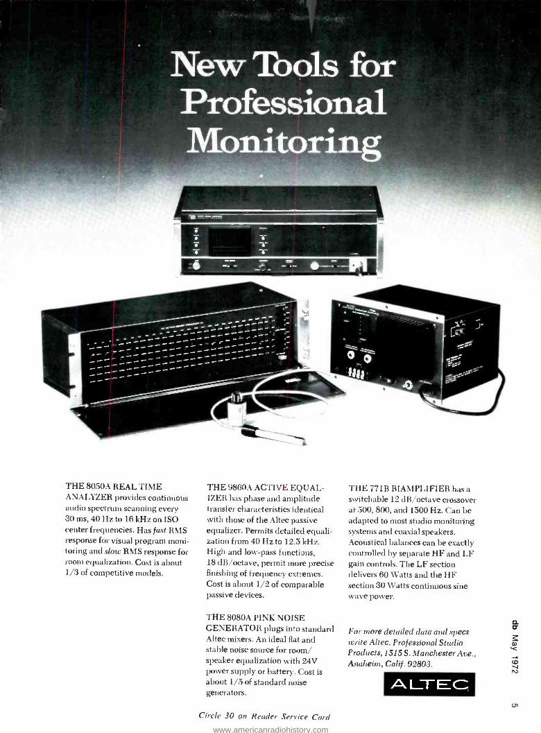
New Tools for Professional Monitoring
THE 8050A REAL TIME ANALYZER provides continuous audio spectrum scanning every 30 ms, 40 Hz to 16 kHz on ISO center frequencies. Has fast RMS response for visual program moni- toring and slow RMS response for room equalization. Cost is about 1/3 of competitive models.
THE 9860A ACTIVE EQUAL- IZER has phase and amplitude transfer characteristics identical with those of the Altec passive equalizer. Permits detailed equali- zation from 40 Hz to 12.5 kHz. High and low -pass functions, 18 dB /octave, permit more precise finishing of frequency extremes. Cost is about 1/2 of comparable passive devices.
THE 8080A PINK NOISE GENERATOR plugs into standard Altec mixers. An ideal flat and stable noise source for room/ speaker equalization with 24V power supply or battery. Cost is about 1/5 of standard noise generators.
Circle 30 on Reader Service Card
THE 771B BIAMPLIFIER has a switchable 12 dB /octave crossover at 500, 800, and 1500 Hz. Can be adapted to most studio monitoring systems and coaxial speakers. Acoustical balances can be exactly controlled by separate HF and LF gain controls. The LF section delivers 60 Watts and the HF section 30 Watts continuous sine wave power.
For more detailed data and specs write Altec, Professional Studio Products, 1515 S. Manchester Ave., Anaheim, Calif . 92803.
A LIT EC m
www.americanradiohistory.com

co
Nortronics ... world's leading de- signer and manufacturer of mag- netic heads ... offers the precise replacement head for virtually every professional recorder .
heads that provide outstanding performance, longest life and easy replacement with minimum down- time. Nortronics' distributors stock the 'right' replacement head for your professional recorder -be it Ampex, Magnecord, Scully, Con - certone, Gates, Crown, RCA, ATC, Collins, KRS, Macarta, MCI, Tape - A -Thon, Sparta, Tapecaster -or any other! See your Nortronics distributor today for professional reel -to -reel orcartridge head requirements. He also carries a complete line of Nor - tronics accessories and offers head relapping services.
world's leader in magnetic heads
6140 Wayzata Blvd.. Minneapolis, Minn. 55416 Minneapolis, Minn. 55416
(612) 544-0381 In Canada
Len Finkler, Ltd. 25 Toro Road, Downsview, Ontario
(416) 630 -9103
Circle 18 on Reader Service Card
6001
3600
750051 (/)OVU=4dbm
Figure 2. Meter pads.
4db PAD
3600 r880 880
late using formula. Pads which are designed to produce
more than 20 dB of attenuation (and accuracy is not of prime importance) values for the resistors are chosen as
follows: If source requires termination then a resistor slightly higher than the required terminating value is selected and used shunted across the source. For instance, if a circuit is 600 ohms and you want to drop level 20 dB, the shunt resistor can be 620 ohms (5% standard value) or 680 ohms (10% value).
Voltage ratio for 20 dB attenuation is 10 /1. If load impedance is 10
k ohms but we want to keep the im- pedance of the pad and interconnect- ing line low, we should select a shunt resistor for the load to be (let us say) 620 ohms. This value in parallel with the 10 k ohm load impedance will give us a combined resistance of 585 ohms. In order to achieve 20 dB attenuation a series element of the pad should be nine times the value of the shunt re- sistance. Since the value in this case turns out to be 5250 ohms, the closest standard value is 5600 ohms. This is
7 per cent off the attenuation target - or a little more than 1/2 a dB.
If you feel you can get better re- sults with other standard values try changing the shunt resistor to 680 ohms. Total shunt resistance will be then 37 ohms. The series resistor then becomes 5720 ohms. Again, using the same 5600 ohm resistor we are only 21/2 per cent off -less than 0.2 of a dB. This is all fine, but we have used 10 per cent resistors and we can be as much as 11 per cent off (10 per cent for the shunt value and 1 per cent as an effect of 10 per cent value vari- ation of the series element). But don't get discouraged. Today's resistors are so good that chances are that you won't be more than a couple of per cent off in the worst case. And you can select resistors if you have enough on hand.
Almost all of today's amplifiers have variable gain so error in the pad can be easily compensated by the gain control. However, when it comes to splitting and combining signals, closer tolerance resistors are needed if accur- acy is imperative. One interesting as- pect of today's mass -produced resistors is that deviation in resistance value is
common to a particular lot and if we
OVU=8dbm
start testing (for instance) 10 per cent resistors from the same batch you will find most of them being of the same value within I or 2 per cent, but all of them several per cent away from the nominal value.
Should you have to make the same pad balanced, divide the 5600 -ohm resistor into two (actually consider 5720 as true value). Dividing, we get a value of 2860 ohms in each leg of the balanced pad. Closest standard value is 2700 ohms. If we use this value we will be 9 per cent off. If we substitute the 680 ohms shunt by a 620 ohm resistor, error will be less than 1.5 per cent.
Let us see what happened to the loading of the source. If we have used 620 ohmms parallel with 6200 ohms of pad resistance, total loading is 565 ohms which is too low. Use 680 ohms, then total resistance will be 618 ohms or 2.5 per cent off.
The higher the attenuation the easier it is to find the value for the pad us- ing this method. If, on the other hand, attenuation has to be low (6 dB isola- tion pad, for example) either use the text book formula or an approxima- tion method when certain conditions exist. Take, for instance, a transitor- ized line amplifier, class AB with an output source impedance of a few ohms (some, with heavy feedback can have 0 ohms source impedance). Ter- mination of such an output is not needed (every load will be bridging anyhow). All you must have is 6 dB isolation from the load which is to see a 600 ohm source. Well what can be simpler -just put a 600 -ohm resistor (two 1200 -ohm resistors in parallel) in series. With this, all conditions will be satisfied.
If you require a balanced pad divide 600 ohms into two resistors. But the closest standard value is 330 ohms, a
5 per cent value is available in 300 ohms. But what if you don't have it
and your dealer doesn't stock them. Then either use 270 ohms in series with 33 ohms, 220 ohms with 82
ohms, 180 with 120 ohms or four 1200 -ohms resistors in parallel.
Let us look at a slightly different kind of pad -a vu meter pad. As you know, standard vu meters are designed to have a 0 vu reading when a series resistor is 3600 ohms and the voltage level is 4 dB above the 1 milliwatt
www.americanradiohistory.com
9!
o-
5- Io- --0- I5- 20- 25-1111- 30-
35- 40- 45 -í
}
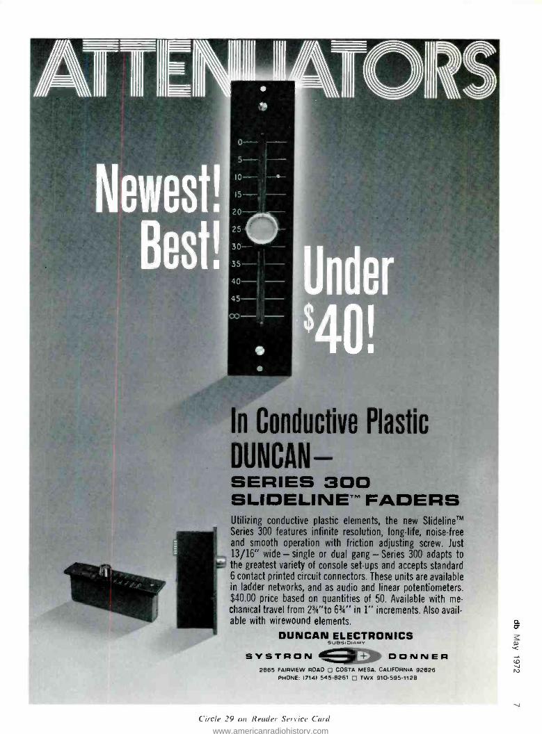
In Convctîve Plastic
DUNCAN- SERIES 300 SLIDELINETM FADERS Utilizing conductive plastic elements, the new SlidelineTM Series 300 features infinite resolution, long -life, noise -free and smooth operation with friction adjusting screw. Just 13/16" wide - single or dual gang - Series 300 adapts to the greatest variety of console set -ups and accepts standard 6 contact printed circuit connectors. These units are available in ladder networks, and as audio and linear potentiometers. $40.00 price based on quantities of 50. Available with me- chanical travel from 23,4 "to 6' -á" in 1" increments. Also avail- able with wirewound elements.
DUNCAN ELECTRONICS
SYSTRON tiuB!+iO1434Y
DONNER 2885 FAIRVIEW ROAD ,] COSTA MESA, CALIFORNIA 92626
PHONE 17141 545 -8261 TWX 910- 595 -1128
Circle 29 on Reader Service Card
www.americanradiohistory.com
co
wáfcpes These are Switzerland's finest quality stop-
watches manufactured by Heuer -Leonidas S.A.
Heuer has been the leading manufacturer
of quality stopwatches for over 100 years.
Their reliability and design leadership are well
known throughout the world.
All are fully guaranteed for one year with
service available in 90 countries. Isn't it time
you had one of these new models? 4
If you are seeking a stopwatch for a special appli-
cation please let us know. Heuer stopwatches are
available for sports, aircraft, automotive, industrial, scientific and many other uses.
Model
502.401
Model
501.201
1/5 second recorder. central 0 -60 minute
register. 2 crown functions with time -out and locked return. 7
Jewels. shock-pro- tested. $58.00
1.5 second recorder, central 0 --60 minute register. 1 crown function with side - slide. 7 jewels, shock - protected. $50.00
FILM- MASTER. 60 second recorder, cen-
tral 0 -60 minute reg- ister. Records on out-
side scale consumed
35 mm film from 1 -90 feet, on intermediate scale consumed 16 mm
film from 1 -36 feet. Framespeed 24 pic- tures /second. 2 crown functions with time -out and fly -hack return. 7
jewels, shockprotected. $61.00
WRIST TIMER for pro-
gram directors in radio, TV and film. 1/5 second recorder, cen- tral 0 -60 minute reg- ister. Dial reading in-
dicates elapsed time; remaining time can be
read on 60 minute turning bezel. 2 crown functions with time-out and locked return button with safety bolt. 7 jewels, shockpro tested: $74.00
GUARANTEE
100% absolute satisfaction or your money returned within 10 days without question. To order send check
directly to:
TIMEKEEPER P.O. Box 835, Great Neck,N.Y.11021
N. Y. State residents add 7% sales tas
level in a 600 ohm circuit -or 1.228 V. Meter resistance is 3900 ohms and with the external multiplier 7500 ohms. Ballistics of the meter are requiring that the meter see a 3600 -ohm circuit for proper damping. If we want our vu to read 8 dBm instead of 4 dBm at 0 vu, our pad should be constructed as follows:
First of all we have to lose 4 dB of voltage in a 600 -ohm circuit. We can make an L pad with a 680 -ohm shunt value and a 470 -ohm series value, thereby obtaining correct loading for the meter damping and proper voltage for indication. But there is one thing wrong -1000 ohms load for just the meter circuit may be too much for some amplifiers. Unless we have power to burn we have to try to design bridg- ing pads.
Usually, a T pad is the most appro- priate pad form in this case. Formula for calculating a T pad is
Ra'R=- (K+ 1 Z
R,- (,K / 2Z K- - 1
Where R 1 and R2 are series resistors R3 is a shunt resistor Z is input and output impedance. K is the ratio of current, voltage and
db binders only $4.95 postpaid
Heavy- weight hinders are now available to hold the thirteen issues of Volumes I and 2. Rich brown leather- grained virgin vinyl, with our name printed in black on the spine and front cover, is electroni- cally sealed over rigid board to give your volumes of db lasting protec- tion. Keep your copies preserved in perfect condition, protected from dust and damage.
EPlease send me the db Magazine check for S
(sorry, no c.o.d.). Name Address
copies of 1 binder. My s enclosed t
number and street
city state aip
(New York State residents please add 6% sales tax).
Mail to: db the Sound Engineer- i
ing Magazine, 980 Old Country Road, Plainview, N.Y. 11803.
power corresponding to a given value of attenuation expressed in dB.
If we insert this T pad between the vu meter and on external 3600 ohm multiplier resistor, input and output impedances become identical and the pad is easier to calculate. If you put a pad between the amplifier or line to be measured and the multiplier, then a different formula for T pad has to be used -the so- called tapered. Since input and output impedances differ
R,=Z, ¡K2 + 11 %K2
-2 ` /Z Z, (K= K
) (K=+ 11
R2 - Z' K2 - 1
-2Z,z (K° K -1)
R, = K-
K 1 2 VZ,Z_( / - 1
Values of K expressions can be ob- tained from the tables by looking up the desired attenuation in dB and cor- responding value of K. Substituting into first formula for T pad values of
%K
+ +
l 1)
K .226 for 4 dB and Z
of 3900
and (KZK 1, - 1.048
we get for RI and R2 value of 880 ohms and for the shunt resistor 8200 ohms. Since we have a series resistor of 3600 ohms, adding 880 ohms it makes it become 4480 ohms. We have a choice of connecting in 4700 ohms and correct the attenuation by trim- ming other values or taking two re- sistors in series, 3300 and 1200 ohms. Resistor of 880 ohms can be simulated using 560 and 330 ohms in series (only little more than 0.1 per cent off).
The most precise calculations can become meaningless if one can not ob- tain correspondingly accurately resis- tance values. Accuracy is meaningful to a point -there is no sense to adjust meter resistors to 0.1 per cent accur- acy if meter movements can be as
much as 5 per cent off. One might say the tolerances add up. They do, but they can also cancel each other out. If the meter reads low and the pad doesn't attenuate enough, the results may be almost perfect reading. It is
our responsibility to use our ingenuity and practical know -how to use this disadvantage to our purpose by learn- ing about shortcuts in designing pads -adjusting their tolerances by using standard resistor values and achieving precision results.
www.americanradiohistory.com
SONY
... ,..Ea 11180
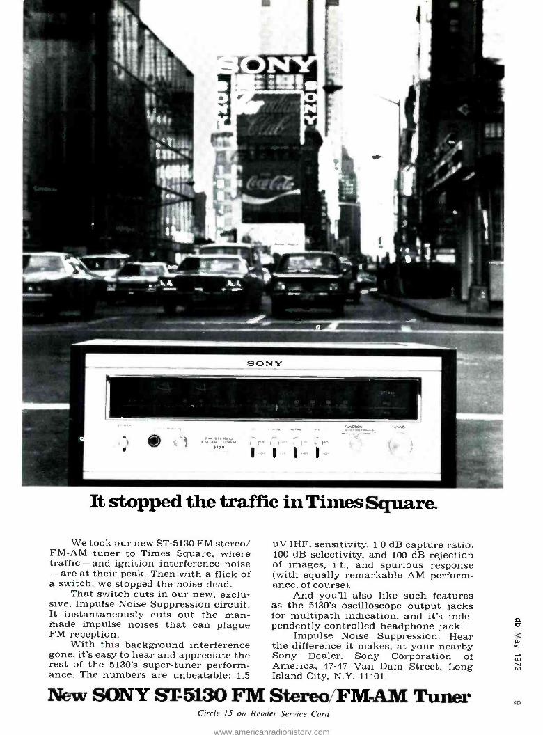
It stopped the traffic in Times Square.
We took our new ST -5130 FM stereo/ FM -AM tuner to Times Square, where traffic - and ignition interference noise - are at their peak. Then with a flick of a switch, we stopped the noise dead.
That switch cuts in our new, exclu- sive, Impulse Noise Suppression circuit. It instantaneously cuts out the man- made impulse noises that can plague FM reception.
With this background interference gone, it's easy to hear and appreciate the rest of the 5130's super -tuner perform- ance. The numbers are unbeatable: 1.5
uV IHF, sensitivity, 1.0 dB capture ratio, 100 dB selectivity, and 100 dB rejection of images, i.f., and spurious response (with equally remarkable AM perform- ance, of course).
And you'll also like such features as the 5130's oscilloscope output jacks for multipath indication, and it's inde- pendently- controlled headphone jack.
Impulse Noise Suppression. Hear the difference it makes, at your nearby Sony Dealer. Sony Corporation of America, 47 -47 Van Dam Street, Long Island City, N.Y. 11101.
New SONY ST 5130 FM Stereo/FM-AM Tuner Circle 15 on Reader Service Card
www.americanradiohistory.com
0
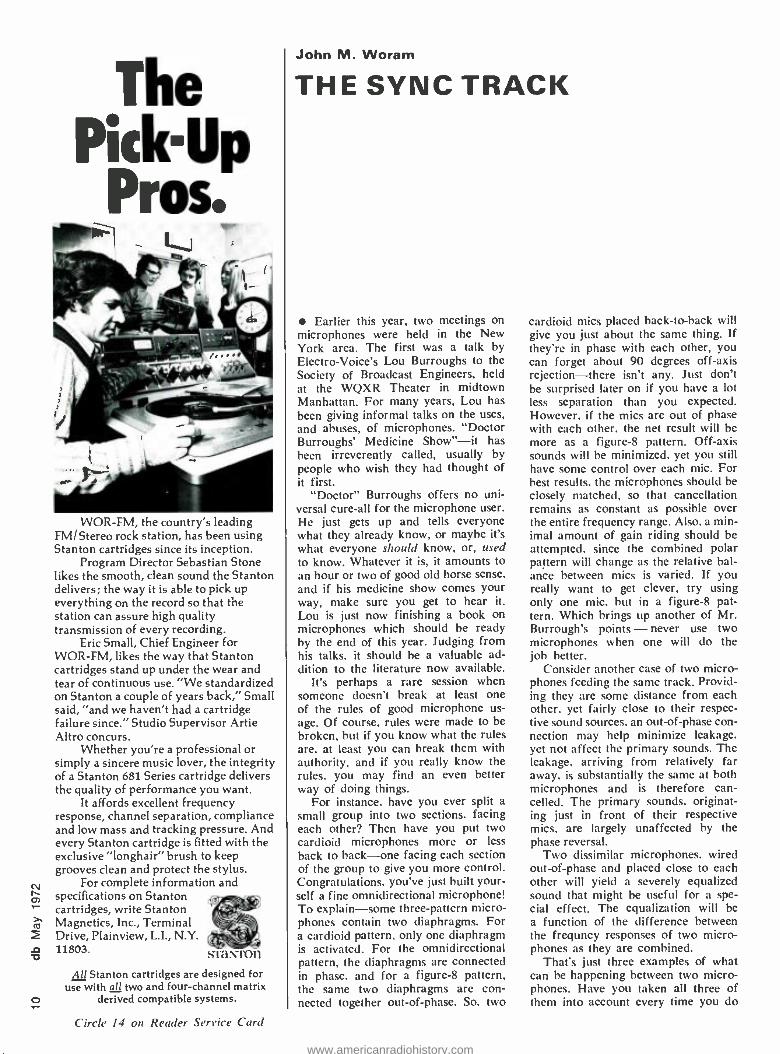
The Pick- p
WOR -FM, the country's leading FM /Stereo rock station, has been using Stanton cartridges since its inception.
Program Director Sebastian Stone likes the smooth, clean sound the Stanton delivers; the way it is able to pick up everything on the record so that the station can assure high quality transmission of every recording.
Eric Small, Chief Engineer for WOR -FM, likes the way that Stanton cartridges stand up under the wear and tear of continuous use. "We standardized on Stanton a couple of years back," Small said, "and we haven't had a cartridge failure since." Studio Supervisor Artie Altro concurs.
Whether you're a professional or simply a sincere music lover, the integrity of a Stanton 681 Series cartridge delivers the quality of performance you want.
It affords excellent frequency response, channel separation, compliance and low mass and tracking pressure. And every Stanton cartridge is fitted with the exclusive "longhair" brush to keep grooves clean and protect the stylus.
For complete information and specifications on Stanton cartridges, write Stanton Magnetics, Inc., Terminal Drive, Plainview, L.I., N.Y. 11803. sraN ron
All Stanton cartridges are designed for use with all two and four -channel matrix
derived compatible systems.
Circle 14 on Reader Service Card
John M. Woram
THE SYNC TRACK
Earlier this year, two meetings on microphones were held in the New York area. The first was a talk by Electro-Voice's Lou Burroughs to the Society of Broadcast Engineers, held at the WQXR Theater in midtown Manhattan. For many years, Lou has been giving informal talks on the uses, and abuses, of microphones. "Doctor Burroughs' Medicine Show " -it has been irreverently called, usually by people who wish they had thought of it first.
"Doctor" Burroughs offers no uni- versal cure -all for the microphone user. He just gets up and tells everyone what they already know, or maybe it's what everyone should know, or, used to know. Whatever it is, it amounts to an hour or two of good old horse sense, and if his medicine show comes your way, make sure you get to hear it. Lou is just now finishing a book on microphones which should be ready by the end of this year. Judging from his talks, it should be a valuable ad- dition to the literature now available.
It's perhaps a rare session when someone doesn't break at least one of the rules of good microphone us- age. Of course, rules were made to be broken, but if you know what the rules are, at least you can break them with authority, and if you really know the rules, you may find an even better way of doing things.
For instance, have you ever split a small group into two sections, facing each other? Then have you put two cardioid microphones more or less back to back -one facing each section of the group to give you more control. Congratulations, you've just built your- self a fine omnidirectional microphone! To explain -some three -pattern micro- phones contain two diaphragms. For a cardioid pattern, only one diaphragm is activated. For the omnidirectional pattern, the diaphragms are connected in phase, and for a figure -8 pattern, the same two diaphragms are con- nected together out -of- phase. So, two
cardioid mics placed back -to-back will give you just about the same thing. If they're in phase with each other, you can forget about 90 degrees off -axis rejection -there isn't any. Just don't be surprised later on if you have a lot less separation than you expected. However, if the mics are out of phase with each other, the net result will be more as a figure -8 pattern. Off -axis sounds will be minimized, yet you still have some control over each mic. For best results, the microphones should be closely matched, so that cancellation remains as constant as possible over the entire frequency range. Also, a min- imal amount of gain riding should be attempted, since the combined polar pattern will change as the relative bal- ance between mics is varied. If you really want to get clever, try using only one mic. but in a figure -8 pat- tern. Which brings up another of Mr. Burrough's points - never use two microphones when one will do the job better.
Consider another case of two micro- phones feeding the same track. Provid- ing they are some distance from each other, yet fairly close to their respec- tive sound sources, an out -of -phase con- nection may help minimize leakage, yet not affect the primary sounds. The leakage, arriving from relatively far away. is substantially the same at both microphones and is therefore can- celled. The primary sounds, originat- ing just in front of their respective mics, are largely unaffected by the phase reversal.
Two dissimilar microphones. wired out -of -phase and placed close to each other will yield a severely equalized sound that might be useful for a spe- cial effect. The equalization will be a function of the difference between the frequncy responses of two micro- phones as they are combined.
That's just three examples of what can he happening between two micro- phones. Have you taken all three of them into account every time you do
www.americanradiohistory.com
a session? Probably not, if you're like most others.
Lou is also a little suspicious of gohos, or flats. While intended to give some additional separation between in- struments, they often do little or no good. Putting a gobo between, say, an acoustic guitar and the other instru- ments in the studio may do more harm than good. If a cardioid micro- phone is being used, the off -axis re- jection of the mic itself is more effec- tive than any flat. Chances are, the leakage you hear is getting into the front of the microphone, via reflec- tions from surrounding surfaces. If you must use a gobo, try putting it
behind the guitar player. You may be surprised to find out it cuts down more leakage there than it did up front. In other words, think about what you are doing. Obviously since the microphone has even less brains than your least favorite producer, it
may need your help in discriminating between sounds arriving from in front. Since off -axis rejection has been built in, you get it whether you want it or not. As you know, this means the mu- sician should be standing in front of the mie, and should not move around much. It also means that you probably don't need flats off -axis. Think about it.
For musicians who must move around, an omni -directional micro- phone may be best, particularly for singers. Unless the singer is sprawled across the floor (it happens) the mic- to- source distance is continually chang- ing. At least with an omni pattern, you can eliminate the varying response due to proximity effect or singing into the mie off -axis. Working the omni mie in a little closer will cut down on the leakage. Even in an isolation booth, it may he a good idea to work an omni mie in close. Often, the trou- ble with a singer in a booth is that she sounds just like a singer in a booth. The isolation booth replaces the sound of leakage with the sound of being in a booth. Moving in close may help get rid of that "music -in -a- casket" sound.
If Mr. Burroughs puts a fraction of his good advice into his hook. it will be a must for everyone who uses mic- rophones. In the meantime, try to get to one of his "medicine shows."
A few weeks after Lou's talk, the New York section of the A.E.S. in- vites Andrew Brakhan of AKG and Peter Giddings of the Beyer Division of Revox to discuss new developments in condenser and ribbon microphones. and to participate in a subjective com- parison of the three well -known types of mies: condenser, ribbon, and dy- namic. As moderator of this meeting. I thought it would he interesting to find out just how readily identifiable
don't delay without a Cooper g'ime Cuba* The only dual delay device available
UREI's unique Cooper Time Cube' gives you TWO completely independent audio delay lines, at less than one -third the cost of a single channel digital unit.
Cost per MS less than 1/3 that of a digital device Lowest distortion, even at low levels (less than .5 %) Excellent signal- - 'se - better than 70db
Excellent fre n ponse, bandwidth 30 Hz to 10 KHz
The Model 920 -1th àtem provides TWO electronically inde- pendent delays: One of 16MS and one of 14MS. They can be used separately, in Quad synthesis or for simultaneous "loud- ness enhancement" of two single channels. Or, the two delay lines may be cascaded for 30MS delay to an "echo chamber" or reverberation device. Model 920 -16 Time Cube is the only acoustical delay line system of professional quality, and is designed specifically for record- ing studio applications and optical film recording.
See your dealer or write for complete specifications.
'Evolved from the rig al design of Dr. Duane H. Cooper of The University of Illinois, in collaboration h T. Putnam of UREI.
alJ company
11922 Valerio Street. No. Hollywood. California 91605 (213) 764 -1500
Circle 20 on Reader Service Card
www.americanradiohistory.com
N
are the much -discussed sounds of the various categories of microphones.
Before the meeting, a tape was pre- pared of several instruments. In front of each instrument, six microphones were set up. Some were ribbons, others condensers, still others dynamics. Each mic was recorded on a separate track. Later on at the meeting, the audience was invited to identify the individual microphones by type. Hardly what one would call an objective scientific ex- periment.
However, we all know by now that the published specs on any mic tell only part of the story. We've heard about the condenser sound, the warmth of a ribbon, transient response, plus a variety of subjective terms by which most people describe their fav- orite microphones. Much of this infor- mation is just not transferable into scientifically measurable parameters.
So, we thought we'd see just how much of the subjective could be re- corded and transmitted to a large audi- ence. Judging by the comments, listen- ers found it far easier to attach a sub- jective value (warm, crisp, mellow, bright) than to accurately identify the particular type of mic. Some con- cluded that the mellow sounds were produced by ribbons and the crisp
mics were condensers. There were perhaps 225 people in the audience, and at no time was there a clear majority accurately identifying the various types.
Most experiments are supposed to have a conclusion, and even this one, despite its lack of scientific pretension, had one. It was -Don't come to any conclusions without listening First.
Anyone who thinks the ribbon mic- rophone is dead should call the Beyer people fast. The old RCA 44 was (and is) a superb mic, despite its fra- gility and size. However, it is not the last thing that has happened in ribbon missing out on something.
The case for condensers hardly needs pleading here. Most studios have at least a few different types around and are familiar with their advantages. The AKG 451 series used in our tests is but one of many excellent conden- sers currently available. How it will sound in your application can only be answered by you, the user. However. for those who are considering a con- denser purchase. I can unhesitatingly recommend it on several counts having nothing to do with its electrical specs; it is quite small, and an impressive collection of accessories, such as ex-
tension tubes and right angle swivel joints are available, as are interchange- able capsules. It's worth a listen.
On my way out to the Midwest Acoustics Conference last month (more about this in the future) I stopped in at the Electro-Voice fac- tory in Buchanan. Michigan. Electro- Voice's Alan Watson is doing some interesting work which he describes in a paper at the 42nd AES Conven- tion. The paper is entitled, "Time Average Holography." To quote the convention program, "Basic relation- ships between diaphragm vibration patterns and response variations are reviewed ". In another paper, Thomas Lininger. also of Electro-Voice, dis- cusses "Microphone Transient Re- sponse Measurement." Again quoting the program, "Transient response in relation to acceptance of a micro phone has been observed and an at- tempt at correlating these observations with analysis of human ear transient response was made." Perhaps in time we shall have it on paper why we like certain microphones. In any case, interested readers are directed to the Audio Engineering Society for fur- ther information.
30° 5°
45°
THE XEDIT -2 the finest 2" tape splicing block you can buy
Small holding ridges will not crimp the tape when it is removed Razor blade fits snugly -makes a straight, neat cut Tough aluminum alloy with clear, anodized finish Custom- machined to extremely close tolerances Cork backing -no slippage 7 "x3" x3/4 "
Sold exclusively by TIMEKEEPER on a 100% money back guarantee. You must agree that this is the best 2" tape block you have used or you may return the unit for a full refund.
N.Y.S. residents add 6% sales tax Price: $80. postpaid (45° cut is optional at $5 additional)
TIMEKEEPER P.O. Box 835 Great Neck, N.Y. 11021
you write it Many readers do not realize that they can also be writers for db. We are al- ways seeking good, meaningful articles of any length. The subject matter can cover almost anything of interest and value to audio professionals.
Are you doing something original or unusual in your work? Your fellow audio pros might want to know about it. (It's easy to tell your story in db.)
You don't have to be an experi- enced writer to be published. But you do need the ability to express your idea fully, with adequate detail and information. Our editors will polish the story for you. We suggest you first submit an outline so that we can work with you in the development of the article.
You also don't have to be an artist, we'll re -do all drawings. This means we do need sufficient detail in your rough drawing or schematic so that our artists will understand what you want.
It can be prestigious to be published and it can be profitable too. All arti- cles accepted for publication are pur- chased. You won't retire on our scale, but it can make a nice extra sum for that special occasion.
www.americanradiohistory.com
U S. á FOREIGN PATS.
MS-200
AGNETIC APE HEAD CLEANER
AO\
don't loss your head Loose oxide dust can do in a tape head all too soon. It's rough on tape, too.
MS -200 Magnetic Tape Head Cleaner` is an efficient antidote for oxide dust. Even the valve on the can is
designed to deliver a wet spray to flush away oxide build- up on heads and stray particles embedded in tape. Can be applied while tape is running.
®miller- stephenson chemical co.,Inc.
Route 7, Danbury, Connecticut 06810
Please send me data and prices on MS -200.
I intend to use MS -200 on:
Name Title /Dept.
Company
Address
City State Zip
CHICAGO LOS ANGELES TORONTO L] DIST. IN MILAN HAMBURG PARIS LONDON
Circle /9 on Reader Service Card
Olive's Automated Remix Programmer. Now you don't have to remember your best ideas.
olive ', Olive E Hc(ro Dynanut s Inc 26711 Pi ulus Montréal 386, Quélær Cal adz 1514) 3.2 -11331
Ca:,kOlivel. Montréal
The Automated Remix Programmer. It monitors and remembers every single operation of your multi -track mixdown. Every movement of fader, pan pot. echo send, whatever.
Then when you're happy with some of the mix, but want to rework perhaps the string section. the Programmer faithfully repeats your satisfactory operations, while you manually remix just the strings. As often as you want, in any combination. All the way to the happy ending.
Olive's Automated Remix Programmer remembers and repeats your best mixing combinations. Which saves up to 75% of the time and energy you're now spending in a mixdown session, because you use your mind for mixing, our machine for remembering. So you're fresher, more creative, more productive.
Contact us for the fascinating details. Your good ideas and our good idea can make a beautiful mix.
Westlake Audio Inc. Harvey Radio Company Studio Supply Company Studio- Technique 6.311 Wilshire Blvd 444 Madison Avenue 112 Cloverdale Court 4 avenue Claude Los Angeles. California New York, N Y. Hendersonville, Tenn Vellefauz 90048 1(X)22 1615)824.5402 Paris (10e) France 1213) 655 -03(13 (212) 582 -15(0 206-1S-60/208-40-99
Circle 16 on Reader Service Card
www.americanradiohistory.com
for that heavy studio sound!
1176 IN
1tiri9 amplifier
the Industry's most popular limiter! over 2000 in use!
Push buttons for four compression ratios Ultra fast attack time, adjustable Independent release time, adjustable Compact 3,/,-x19" rack
See your dealer or wife for complete spec,hcahons.
11922 Valerio Street No. Hollywood, Cahlomw 91605 (213) 764 -1500 Exclusive export saes, GOTHAM AUDIO DEVELOPMENT CORP. NEW YORK N Y
Tema 233353 GAOC OR
Circle 28 on Reader Service Card
ti 2
; 'X
14C HEp
Norman H. Crowhurst
THEORY AND PRACTICE
The other day I received a religious publication, in which the editor has an article on situation ethics. He points out that, while in general it would be wrong to break into your neighbor's house, if a situation occurred whereby you could save his life only by break- ing into his house, then it would be wrong not to break in.
Reading this made me realize how given people are to one or another form of absolutism. And we in audio are by no means exempt from this. How many articles have been written about crossovers and phase problems? This is still an area where theory and practice are poorly related, by many. I read an article on this subject re- cently, in which the author called at- tention to the need for optimizing a network with the actual loudspeaker impedances, rather than using values based on a hypothetical resistance load.
I think that was the first time I had read that, when I was not proof read- ing one of my own articles. So I was pleased to see that the author gave me credit in the bibliography he ap- pended to the article. Now comes a letter from a reader, asking about the use of electronic crossovers in con- junction with mixing. What he has in mind is the use of a single channel to handle frequencies below 100 Hz, with the usual separated stereo above that frequency.
He wants to know if the below 100 Hz outputs from two stereo channels of electronic crossovers can be mixed into a single channel for below 100 Hz. He adds that much has been said and indicated by so- called authorities that mixing out of such a source can
for you, the profeffiono The Gray 6400 Pre Amplifier
Become acquainted with the Gray 6400 Series Turntable Pre -Amps. Re-
alize the high quality reproduction they'll provide. Higher outputs (0 dBM into 600 OHMS) and smaller packages than ever. Three output curves fully adjustable to match re
quirements. Monaural (6400) Stereo (6401). Complete specifications at your request. . You'd probably worry about it if it wasn't from Gray.
GRAY RESEARCH ND DEVELOPMENT COMPANY DIVISION
Circle 25 on Reader Service Card
he woefully derogatory of signal, its total output, its phasing with the upper channels, and phase cancelling within the mixed section.
He does not name his authorities. I
do not recall reading that kind of thing anywhere, but that does not say it has not been printed. It could be that some fairly technicaly informed sales- man started it, because you can sell more bass units that way. But here was a case where so many variables are involved that no simple answer is possible. However, I would have to take issue with the basic import of his prior information.
First let's take the points mentioned. The problem of getting phasing correct between each upper frequency stereo output and the common bass unit. In a multiway system on a single channel, the usual practice is to have the units close together and phase them so that frequencies in the vicinity of crossover -in this case 100 Hz- emerge in phase. You can use either theory or practice or a combination of both, to achieve this result.
Now, the argument seems to be, if you separate the bass unit from each upper -range unit or units, then this emergence -together feature is no longer possible. That's true, until you realize that the crossover frequency represents a wavelength of 11 feet. Presumably one reason for wanting to combine the bass is limitation of space -it is for use in a small room. such as an apart- ment. So how far apart will the speak- er units be?
Probably 4 or 5 feet at most. This is fairly good proximity. when you are talking about a crossover at this frequency. In a small room. if you had full range units for both stereo channels, and they were connected out of phase, or so the frequencies below 100 Hz get reproduced out of phase, the error would show in two ways. Program intended to come from cen- ter, and thus having equal signal from both channels, would suffer from what has been called the dissociation effect -it gets lost and sounds more as re- verberation than original source sound.
Also, due to the fact that the room is relatively small, there will be a loss of bass frequencies, below 100 Hz particularly. This is because one unit will be blowing when the other is sucking. producing little or no result- ant sound pressure in the room at these low frequencies. Put them in phase, and the bass is good.
www.americanradiohistory.com
So the phase cancelling that can oc- cur within the mixed section can also occur in the room where separate channels are used, perhaps not quite to the same degree, but enough to de- teriorate performance quite seriously.
One wonders whether these so- called authorities were around when CBS as- tounded the world with their demon- stration of the "isophonic" principle. This used a system in which the bass, below 250 Hz (so it must work for be- low 100 Hz) came from a concealed bass unit, under the davenport (or whatever you call that piece of furni- ture locally), while left and right stereo units of quite small size handle the rest of the range. Nobody could tell that the string bass did not come from where it was supposed to come from.
This is because, as earlier experi- ments had demonstrated, our sense of direction is based on the initial parts of sounds -initial transients. Our sense of location was based (and still is, as far as I know) on the pluck or bow sounds at the beginning, and our hear- ing could not unfool us about where the rest of note came from. So, espe- cially for small rooms, such a system works fine, and saves quite a bit of space.
There is another factor here, also related to room size. Someone may object that it is possible to locate low frequency sounds aurally, and quote the fog horn as an example. But one detects the direction of a fog horn in a location out over the open sea, with no walls to create reflections, much less to contain the low -frequency sound. When we listen in any confined space, such as a room, our hearing faculty, which includes the interpretive faculty of the brain, as well as a pair of ears, registers the characteristics of the room in which we hear the sounds.
Generally, this faculty gets us to ig- nore the room characteristics, while concentrating on the content of the sound that comes with it. So the low frequencies are "mussed up" by the room, and our hearing faculty goes to work on information from the other frequencies, while appreciating the bass note information en masse. Out- doors, it may be different, but this con- dition is imposed on us by listening in a relatively small space.
There is one possibility we should mention, related to program content, which can never be ignored. For what we may term normal stereo, where everything is left, right, or somewhere in between -no problem. Frequencies below 100 Hz are either in phase or so close to in phase that the resultant will not be materially affected (on a dB scale) by electrically mixing. But some recordings use another device to
get special effects. They put some corn - ponents of program deliberately out of phase, on the two channels, to use a dissociation effect. If these parts hap- pen to include bass elements, then these will get cancelled.
But this is not such a serious loss as it first appears, especially if you are listening in a small room, as we pointed out earlier, acoustic cancella- tion will occur at these frequencies, even where separate channels are used. So, either way, when the recording does this, you are going to suffer a
bass loss, if you listen in a small room. That about covers the thing from
a system point of view. Now a little attention to the nuts and bolts. How do you connect the two below -100 -Hz outputs together -just parallel them? We would suggest that, as protection against improper operation of the elec- tronic crossover units should any com- ponent frequencies from different channels want to cancel one another. each ouput from the crossover units be fed through a series resistor to the common -channel input for below 100 Hz.
The value of this resistor could be about one fifth of the nominal im- pedance of the circuit. If the circuit is high impedance, meaning 100 k, then a resistor of the order of 20 k in each lead will serve. It is not critical.
As with any stereo system, the whole system should be correctly phased. This may be a little more diffi- cult to do when the units are not all close together. Getting each channel's multiway units correctly in phase with- in that channel is one thing, and phas- ing left and right is something else, in a normal system, with two full -range channels. The common -bass system in- volves an element that fits neither of those jobs exactly.
Probably the best way to check for correct phasing between the common - bass channel and the separate higher - range channels, is to put all the speak- ers in close proximity, either before or after you check for proper stereo effect over the upper range, with the speakers separated.
moving Have you sent us a change -of- address notice? It takes time for us to change your plate so let us know well in advance of your move. Be sure to send us the complete new address as well as your old address. Include both zip numbers. Keep db coming without interruption!
CONSULTANTS IN
ARCHITECTURAL ACOUSTICS
specializiing in
Room Acoustics Sound Isolation
Sound System Design HVAC Noise and Vibration Control
Auditoriums/Theatres /Sports Stadiums Coliseums /Churches /Synagogues Conference Rooms /Board Rooms
Concert and Recital Halls Music Buildings
Service available with collaborating consultants in
Audio Visuals Theatre Technology
Klepper Marshall King Associates, Ltd.
333 Old Tarrytown Road White Plains, N.Y. 10603
(914) 761 -8595
Circle 21 on Reader Service Card
THE NEW KM 88. UP CLOSE...
ATADISTANCE There's a special bright- ness and an extra sheen to the sound of the new KM 88.
Qualities you've heard before -in the KM 56 tube model.
Like that popular earlier model, the KM 88 is the smallest three -pattern microphone made.
It is the only fet -80 Phantoms Powered mike whose dual membranes are made of nickel -the secret of its unique, characteristic sound.
The KM 88 permits distant pickup with close -up quality. (And it has a 10 dB overload switch, as usual.)
Progress can have a familiar sound.
For more information call or write:
G casOTHAN1 AUDIO CORPORATION
2 West 46th Street. New York. NY 10036 (212) 265.4111
1710 N. Leeres Avenue. Hollywood. CA 90046 (213) 874 -4444 In Canada'. JMar Electronics Ltd.
Circle 23 on Reader Service Card
www.americanradiohistory.com
NEW PRODUCTS AND SERVICES
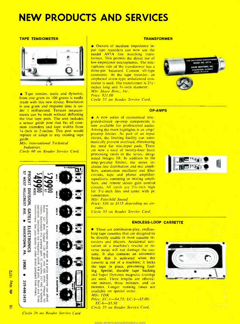
TAPE TENSIOMETER
í d
Tape tension, static and dynamic, from one gram to 100 grams is easily made with this new device. Resolution is one gram and response time is un- der 1 millisecond. Tension measure- ments can be made without deflecting the true tape path. The unit includes a sensor guide post that fits all com- mon recorders and tape widths from N -inch to 2- inches. This post would replace or adapt to any existing tape guide. Mfr: International Technical
Industries. Circle 60 on Reader Service Card.
TRANSFORMER
Owners of medium impedance in- put tape recorders can now use the model A97A line matching trans- former. This permits the direct use of low -impedance microphones. The mic- rophone side of the transformer has a three -pin balanced Cannon xlr -type connector. At the tape recorder, an amphenol screw -type unbalanced con- nector is used. The transformer is 2½- inches long and 3/4 -inch diameter. Mfr: Shure Bros., Inc. Price: $21.00 Circle 52 on Reader Service Card.
,.w, M MSa
MODE, NO 19-,a a
514011 11O1N11S INC
1yß N. ILLINOIS
a 3z »O °"OD 0-;;m5,
m N -
ro V
' Fö ..*Ft d m-=a- mn 11 Q o Am'a3n óam' 0m3O;
c
IaE i D D - -2d+m °óóó 0.0. 3
n d m°çx : GaPI s
.d.
ñ n m 9 0?' C O D Om»óa
.
9DQOm dO oT
3mnm o¡m aDow
aÿdm ^1.-x o á.c?
x
Circle 26 on Reader Service Card
OP-AMPS
A new series of economical inte- grated- circuit op -amp components is now available for professional audio. Among the main highlights is an amp/ preamp limiter. As part of an input circuit, the limiting facility can auto- matically prevent overload, eliminating the need for mic -input pads. There are now a total of twenty -four basic processing cards in the series, desig- nated Integra III. In addition to the amp / preamp limiter, the series in- cludes line distribution and mic ampli- fiers, automation oscillator and filter circuits, tape and phono amplifier - equalizers. summing or mixing ampli- fiers, and remote stereo gain control circuits. All cards are 21/2 -inch high for 31/2-inch files and come with pc connectors. Mfr: Fairchild Sound Price: $30 to $115 depending on cir-
cuits. Circle 53 on Reader Service Card.
flrerAlk
ENDLESS -LOOP CASSETTE
These are continuous -play, endless - loop tape cassettes that are designed to be directly usable in most cassette re- corders and players. Accidental acti- vation of a machine's rewind or re- verse mode will not damage the cas- sette. It also contains an automatic brake that is activated when the cassette is out of a machine; it locks the tape in place, preventing foul- ing. Special, durable tape backing and Super Dynamic magnetic coatings are used. Three lengths are offered: one minute, three minutes, and six minutes. Longer running times are available on special order. Mfr: TDK Price: EC- 1- $4.75; EC -3- $5.00;
EC -6 -$5.50 Circle 55 on Reader Service Card.
1.-d
www.americanradiohistory.com
A Note from the Publisher
We are gratified to offer a very unusual and extremely worth- while new service to our readers; a service that is a means of achieving a goal we've had from our very beginning.
We stated in our initial editorial in November 1967: "In a field as broad as professional audio has become,
the dissemination of information necessary to the im- provement of performance becomes vital. However, with the exception of the highly respected professional soci- eties, no one has yet come forth to provide such service. db's emphasis, therefore will be to complement the theo- retical orientation of existing publications with a focus on practical new concepts.
"Our purpose is to establish an intra- industry dialogue -an exchange of ideas -with immediate relevance to everyday applications."
Starting this month, we are offering db readers a way to achieve this interchange of ideas that is simple and efficient - a way to build on the ideas in our articles with other involved readers -without the time and expense of travel. It is called db TeleSessions -group telephone conferences held in connection with selected db articles. You will be able to dial into one or more hour -long, freewheeling discussions in connection with an article you find especially provocative. You can exchange expe- riences and ideas with a small group of other readers as con- cerned and involved with that area as you are.
A key ingredient in these TeleSessions is the other readers who participate. You will find that each of them is involved and experienced in activities where success often depends on empirical results. This is a chance for you to learn from other experiences instead of from expensive trial and error.
Before launching this joint project with TeleSession Company (which has run over 700 sessions), we reviewed the results of prior sessions. Participants were from very different job levels and functions. They found the TeleSessions not only stimulating, but a low -cost form of consulting that gave immediate answers.
On the inside of the back cover, you will find a complete description of the way TeleSessions work, including the ways in which they are different from conference calls and how you can participate.
For example, after reading this month's article AUTOMATING THE AUDIO CONTROL FUNCTION, you can discuss ideas with other readers who are affected by these developments. Your session might explore the ways to use this technology in your particular field, or it might focus upon an exchange of ideas and informa- tion about new marketing problems, or how this technique can be adapted to specific needs.
On the other hand, readers most interested in building their own consoles or mixers will be dialing into the TeleSession based on ideas within the article A STEREO CONSOLE You CAN BUILD.
We have invited the authors as well as other experts to join our readers in TeleSessions and become involved in the discus- sions. These are just a few examples of the content of your db TeleSessions, for of course the actual direction of each discussion depends on the unique questions and contributions each partic- ipant offers.
We will select one or more articles or columns from each issue in the coming months to be the basis for TeleSessions.
We urge you participate in one or both of these electronic meetings.
Robert Bach Publisher
www.americanradiohistory.com
00
RICHARD FACTOR and STEPHEN KATZ
The Digital Audio Delay Line All electronic control of delay and reverberation is a reality today, with products of several manufacturers already available. The authors examine the function and value of digital systems.
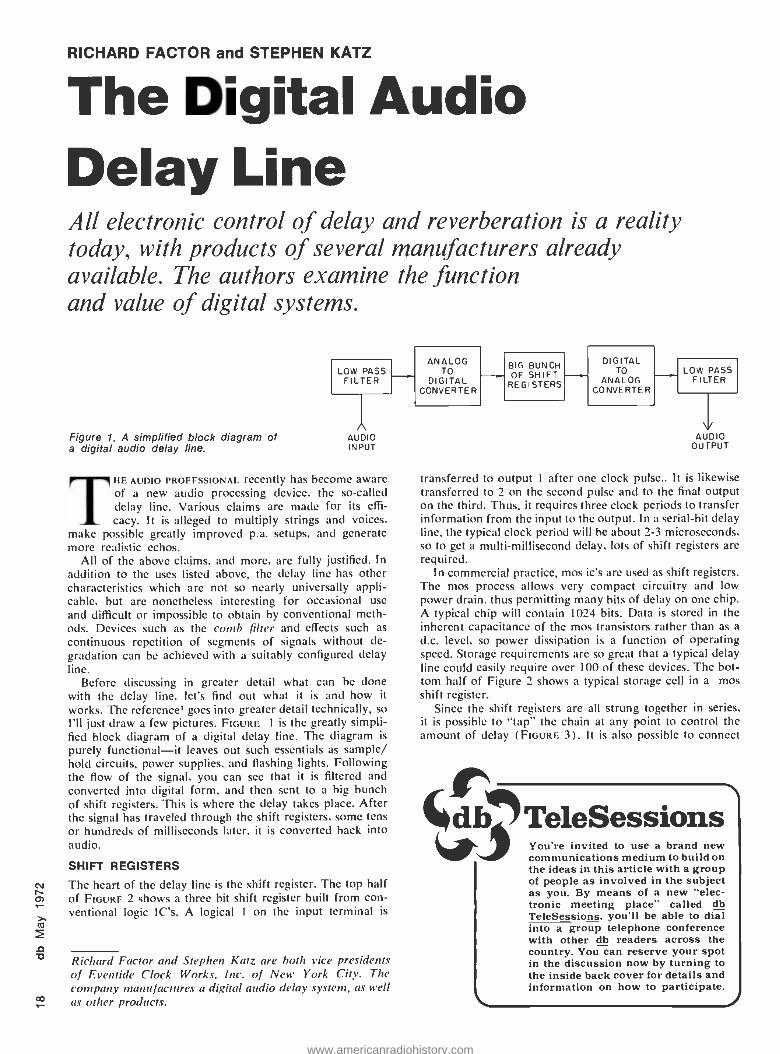
Figure 1. A simplified block diagram of a digital audio delay line.
LOW PASS FILTER
A AUDIO INPUT
THE AUDIO PROFESSIONAL recently has become aware of a new audio processing device, the so- called delay line. Various claims are made for its effi- cacy. It is alleged to multiply strings and voices,
make possible greatly improved p.a. setups, and generate more realistic echos.
All of the above claims. and more, are fully justified. In addition to the uses listed above, the delay line has other characteristics which are not so nearly universally appli- cable, but are nonetheless interesting for occasional use and difficult or impossible to obtain by conventional meth- ods. Devices such as the comb filter and effects such as continuous repetition of segments of signals without de- gradation can be achieved with a suitably configured delay line.
Before discussing in greater detail what can be done with the delay line, let's find out what it is and how it works. The reference' goes into greater detail technically, so I'll just draw a few pictures. FIGURE 1 is the greatly simpli- fied block diagram of a digital delay line. The diagram is
purely functional -it leaves out such essentials as sample/ hold circuits, power supplies, and flashing lights. Following the flow of the signal, you can see that it is filtered and converted into digital form, and then sent to a big bunch of shift registers. This is where the delay takes place. After the signal has traveled through the shift registers, some tens or hundreds of milliseconds later, it is converted back into audio.
SHIFT REGISTERS
The heart of the delay line is the shift register. The top half of FIGURE 2 shows a three bit shift register built from con- ventional logic IC's. A logical I on the input terminal is
Richard Factor and Stephen Katz are both vice presidents of Eventide Clock Works, Inc. of New York City. The company manufactures a digitpl audio delay system, as well as other products.
ANALOG TO
DIGITAL CONVERTER
BIG BUNCH OF SHIFT
REGISTERS
DIGITAL TO
ANALOG CONVERTER
LOW PASS FILTER
V AUDIO
OUTPUT
transferred to output I after one clock pulse.. It is likewise transferred to 2 on the second pulse and to the final output on the third. Thus, it requires three clock periods to transfer information from the input to the output. In a serial -bit delay line, the typical clock period will he about 2 -3 microseconds. so to get a multi -millisecond delay, lots of shift registers are required.
In commercial practice, mos ic's are used as shift registers. The mos process allows very compact circuitry and low power drain, thus permitting many bits of delay on one chip. A typical chip will contain 1024 bits. Data is stored in the inherent capacitance of the mos transistors rather than as a d.c. level, so power dissipation is a function of operating speed. Storage requirements are so great that a typical delay line could easily require over 100 of these devices. The bot- tom half of Figure 2 shows a typical storage cell in a mos shift register.
Since the shift registers are all strung together in series, it is possible to "tap" the chain at any point to control the amount of delay (FIGURE 3). It is also possible to connect
% b- 7TeleSessions You're invited to use a brand new communications medium to build on the ideas in this article with a group of people as involved in the subject as you. By means of a new "elec- tronic meeting place" called db TeleSessions, you'll be able to dial into a group telephone conference with other db readers across the country. You can reserve your spot in the discussion now by turning to the inside back cover for details and information on how to participate.
www.americanradiohistory.com
FAIRCHILD SOUND EQUIPMENT CORP
ENGINEERING DATA POWER SUPPLIES
FIoBINJB INOUSTRIE9 Go n P. s ummit iA1ms/
15 -56 127" ST FLUSHING, NEW YORK 11356 212 445 -7200
(d)
(f)
(e)
(c) (b)
(ET)
(a)
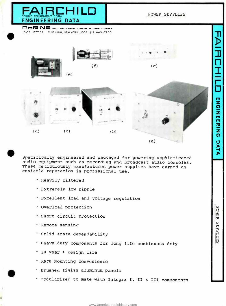
Specifically engineered and packaged for powering sophisticated audio equipment such as recording and broadcast audio consoles. These meticulously manufactured power supplies have earned an enviable reputation in professional use.
Heavily filtered
Extremely low ripple
Excellent load and voltage regulation
Overload protection
Short circuit protection
Remote sensing
Solid state dependability
Heavy duty components for long life continuous duty
20 year + design life
Rack mounting convenience
Brushed finish aluminum panels
Modularized to mate with Integra I, II & III components
n z
0
www.americanradiohistory.com
(D a r n .-3 x-3 r 0"0 H Orrt`^ r-7"OMH7 rt . a ID (D 7 O fD O o 7 'C r re- Ii H a'0 r'O a r ID 'D a000 00 ITJOO
O p' ( £ D a f6 << Ñ E fD
1-1 Ñ N 1-4
H 1-4 11 b 7 7 0 0 a ra f7- a (D O C r G C
roóx0c 0-CI ro O a E K K OK
b rr a 7 I
a 7' tD a r a < a < a a
'GO .Á r O 1-r á 7 rr.
c i á á 1 r v 7 4 a < fD < 0 .A
? 1.-.- (D G Ñ fD a
a a 7 a p: < 11 7 7 r r o a r- r r O o
0 0 r-i rr G O 7' (D (D r a 4 Ti a 4
> a.á
7 a 11 01 (1'
0 Ñ Hfn 1-, UN r(D rt W xl 7 7 ro O rr xra Ill 7r HI MOK II r 0 a a
I
r G
U r O ' ( D I (D Ñ < p. r (D r-' :.: O rt , a a 7 a a .
G.1 X +ro a Ó O rt
O ro (D C 7I 1-1 HI Cu rt (D r r a rt rt !D a '0 r 7,- rt
I
rX Ñ
I
on I (D 11 M a ri II a a r
(D O t1 = r 7 £ Ññ L 74 ( O .- rt a rr - (D
O 7 '0 r X D.) 17 r I rt
Ó i G W G 0 <?(D C (D q m< a.(Dm 'p H O , rr' O 0 G ` rr
`.< r O r rt a£ Ñ
G7 rr D r 7 o ti O
( r rt D
I a £
7 0, 7 r £
Ac m O H.
(D 7 0 3 7 b r rt rt G O r a K r
IL 7 a 0 rt a co rA 0 rt. (D DI 7 a- H rt (D r a O G. 7 7 a a a
CJ
O O r 7 r a X M 11 r 0
7 Ñ O a ( Ó
I0 rt
h rO O (1) '0 I-' Á <D O rt. 70 a r 11 aHt', I 0 rt
Ó 1-00 O rt O(D
G o 11 O a 0 a r m a r* fl- 0
1-1- 'c ç
I y a I Mm C C 11
G O(rD a 5 a Or (D a rr 'O O 11 0 aá°, .-1, ó rOr
DJ
rar -- HI Ñ 1G r 1 0 7 r C
r (D (OD
A tD
(n rt 0 < 0 000 Á' á r( <o
rt 4 U rt. M
I 7 á Ñ Ñ rt a
O .. J a, o, a1 o, ON ON ON ON O, ON ON o, L: 0 ,iY Q N l4 l'J a1 ON ON ON O, ON ON a, O, N `' 7--- .-3 lli N N J J -4 -4 J J
yJ yJ J A
(7 a a 'r1 ri) rn \ \ \ \ \ H O O f cn \ \ N r M N) H \ \ H 7(t N T A V1 H A co N) N rt a M1 A -4 A I-'. C 7 a r C 7 r O a Ñ a O r ÿ (D (D 0' G .+ 0 a a a a a O .
raa K rr a
I-.-
W 7I z r r r r r r r r r r r r 11 r r r r r r r r r r r r r rt r O r -4 J J J J J J J J J J J (D
7 (Oo r7 (D N< a, a, ON ON a,
O a I I I I 1 I I
rt II I I I I I I W l.1
. W l.J I 0 r
n a I+ r- I+ N N
A r O r N I I Ó, N H N N r, N
---- 7 111 A ON N N A 9 J A CO W A A U+ o " rt, :7
p Ó v "1 7 7 r I N) H
R3 4 I 1 I P Vt O, I I I I I r O O I I I I I I I I CJ r< 0 0 W
tat CI' O 0 0 0 r r W O O o o o N
W . . . O H o r v+ o O o r H r W W O
N) U1 CO V1 U1 UN C
C a a K o o 0
.N.) H N 11 =
tZ < o o o
r 11 U1 0 0 J J 0 G
o o (al
rt - N A 0 O -
cc
< M I I I r a 7 al X D
I I t
a 0 o o O O 0 r o N U 1
7 rt rt O
o, r I-, G
0 0 r o 0 0 0 o r H r 0 r H H H H O
O o 0 0 0 0 0 o O H r H r H H W W J
U1
:J H N H H O H H O 0 0 O O o U 1 O O
7 a
Ñ (KD Ñ Ñ (KD CD (D (KD Ñ Ñ O U) a In U) a a fn a !n O
0 O r r W 0 O O O 0 N
A r r r H H H A r 7 N N CT a
a a
7 r O
17 N
Cn 0 I I
I r r r I
I I I
t r N rD7 K á á E 11 r N W W a1 0, ON W W a, a, a, ON I-.. rt or .Jr ar ar X X X X X X X X X a 7 X X x Ut ln U1 ln v1 UI U1 U+ U1 O J U1 1..77 ä dr or di >\' or or r.0 ar _ _ X X X X X X X X X (D O r r r ao co H H H H r 0 O O 1 1 H H r o
O. J u o r r r W W r r S _
'O
r a rr J o, ON (D J N) ON 0 O, l0 a, O, ON O, ON ON ON a, o, a N VI l0 N .0 N a, a, a, ON ON a, ON ON O, MI
Ul () N Et) N7 0) N N1 ;NO
N N N1
N N1 N a (] 3w sx 3 3 3 3 3 3 3 3 x
1°1 o O 11 11
-rro On 0 v p, Ñ
C-1
N
C 5 H
z
AI >
£o M a
www.americanradiohistory.com
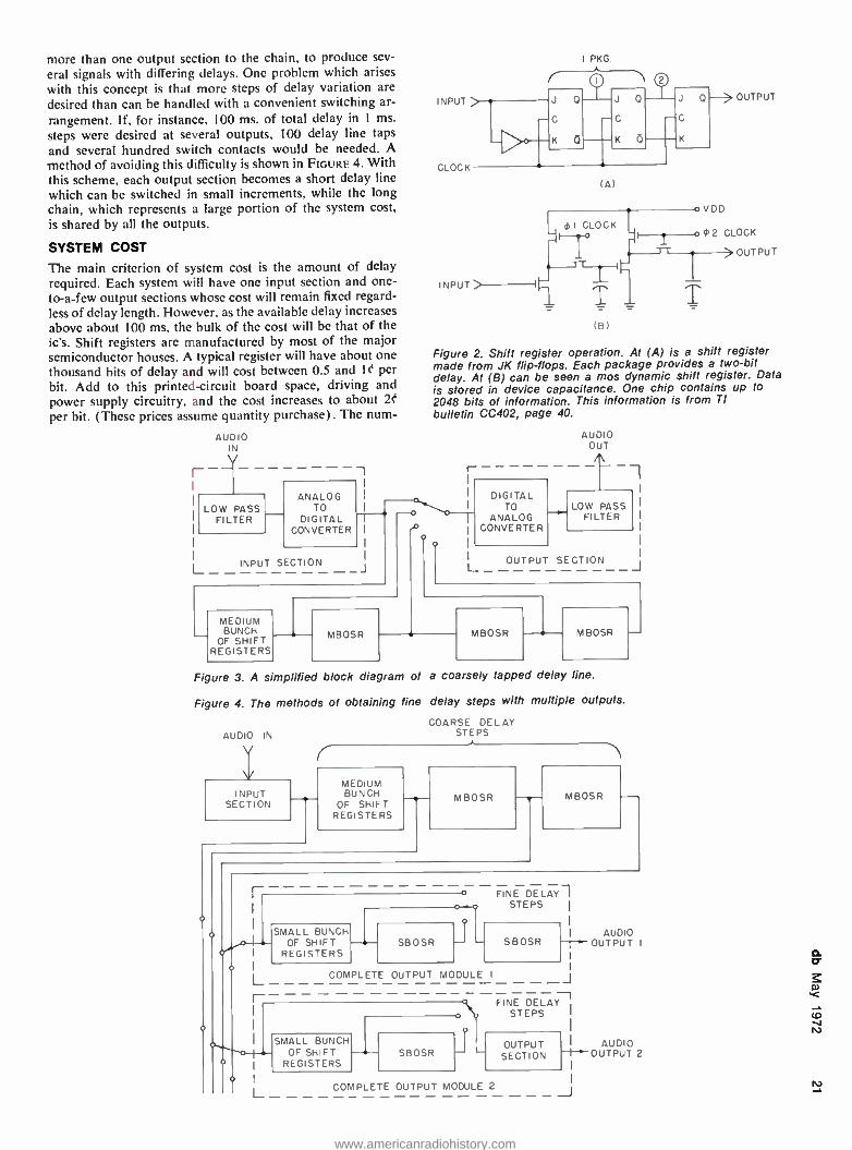
more than one output section to the chain, to produce sev-
eral signals with differing delays. One problem which arises
with this concept is that more steps of delay variation are
desired than can be handled with a convenient switching ar-
rangement. If, for instance, 100 ms. of total delay in 1 ms.
steps were desired at several outputs, 100 delay line taps
and several hundred switch contacts would be needed. A method of avoiding this difficulty is shown in FIGURE 4. With this scheme, each output section becomes a short delay line which can be switched in small increments, while the long chain, which represents a large portion of the system cost, is shared by all the outputs.
SYSTEM COST
The main criterion of system cost is the amount of delay required. Each system will have one input section and one -
to -a -few output sections whose cost will remain fixed regard- less of delay length. However, as the available delay increases above about 100 ms, the bulk of the cost will be that of the ic's. Shift registers are manufactured by most of the major semiconductor houses. A typical register will have about one thousand bits of delay and will cost between 0.5 and 10 per
bit. Add to this printed- circuit board space, driving and
power supply circuitry, and the cost increases to about 20
per bit. (These prices assume quantity purchase). The num-
AUDIO IN
LOW PASS FILTER
1
ANALOG 1
TO DIGITAL
CONVERTER I
1
1
_J L INPUT SECTION
MEDIUM BUNCH
OF SHIFT REGISTERS
-o
--0- MBOSR
INPUT
(A)
I CLOCK o VDD
OUTPUT
o (F 2 CLOCK
OUTPUT
(B)
Figure 2. Shift register operation. At (A) is a shift register made from JK flip- flops. Each package provides a two -bit delay. At (B) can be seen a mos dynamic shift register. Data is stored in device capacitance. One chip contains up to 2048 bits of information. This information is from TI bulletin CC402, page 40.
I-
DIGITAL TO
ANALOG CONVERTER
AUDIO OUT
i
LOW PASS FILTER
OUTPUT SECTION J
MBOSR MBOSR
Figure 3. A simplified b lock diagram of a coarsely tapped delay line.
Figure 4. The methods of obtaining fine delay steps with multiple outputs.
COARSE DELAY STEPS AUDIO IN
INPUT SECTION
MEDIUM BUNCH
OF SHIFT REGISTERS
MBOSR MBOSR
SMALL BUNCH OF SHIFT
REGISTERS SBOSR
FINE DELAY STEPS
I AUDIO 1 OUTPUT I SBOSR
COMPLETE OUTPUT MODULE I
r-- SMALL BUNCH
OF SHIFT REGISTERS
SBOSR
FINE DELAY STEPS
SECTION AUD OUTPUT 1_4_,._
OUTPU1T 2
I L COMPLETE OUTPUT MODULE 2 IV J
www.americanradiohistory.com
N N
700 F
600
500
400
300
SYSTEM FREQUENCY RESPONSE
5 10 15 20 30 KHZ KHZ KHZ KHZ KHZ
100 200 300 400 500 KILOBITS OF SHIFT REGISTER REQUIRED
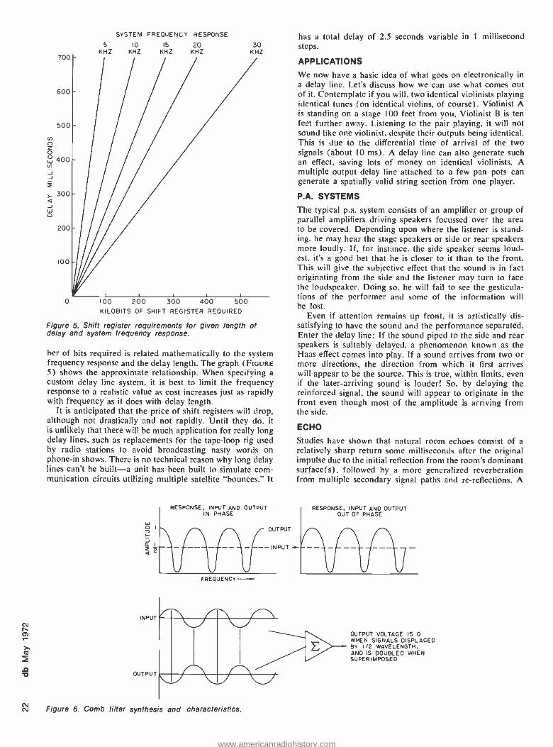
Figure 5. Shift register requirements for given length of delay and system frequency response.
ber of bits required is related mathematically to the system frequency response and the delay length. The graph (FIGURE 5) shows the approximate relationship. When specifying a custom delay line system, it is best to limit the frequency response to a realistic value as cost increases just as rapidly with frequency as it does with delay length.
It is anticipated that the price of shift registers will drop, although not drastically and not rapidly. Until they do, it is unlikely that there will be much application for really long delay lines, such as replacements for the tape -loop rig used by radio stations to avoid broadcasting nasty words on phone -in shows. There is no technical reason why long delay lines can't be built -a unit has been built to simulate com- munication circuits utilizing multiple satellite "bounces." It
w c
I
f J a I
á
INPUT
OUTPUT
RESPONSE, INPUT AND OUTPUT IN PHASE
OUTPUT
-- INPUT
FREQUENCY
has a total delay of 2.5 seconds variable in 1 millisecond steps.
APPLICATIONS
We now have a basic idea of what goes on electronically in a delay line. Let's discuss how we can use what comes out of it. Contemplate if you will, two identical violinists playing identical tunes (on identical violins, of course). Violinist A is standing on a stage 100 feet from you, Violinist B is ten feet further away. Listening to the pair playing, it will not sound like one violinist, despite their outputs being identical. This is due to the differential time of arrival of the two signals (about 10 ms). A delay line can also generate such an effect, saving lots of money on identical violinists. A multiple output delay line attached to a few pan pots can generate a spatially valid string section from one player.
P.A. SYSTEMS
The typical p.a. system consists of an amplifier or group of parallel amplifiers driving speakers focussed over the area to be covered. Depending upon where the listener is stand- ing, he may hear the stage speakers or side or rear speakers more loudly. If, for instance, the side speaker seems loud- est, it's a good bet that he is closer to it than to the front. This will give the subjective effect that the sound is in fact originating from the side and the listener may turn to face the loudspeaker. Doing so, he will fail to see the gesticula- tions of the performer and some of the information will be lost.
Even if attention remains up front, it is artistically dis- satisfying to have the sound and the performance separated. Enter the delay line: If the sound piped to the side and rear speakers is suitably delayed, a phenomenon known as the Haas effect comes into play. If a sound arrives from two or more directions, the direction from which it first arrives will appear to be the source. This is true, within limits, even if the later -arriving sound is louder! So, by delaying the reinforced signal, the sound will appear to originate in the front even though most of the amplitude is arriving from the side.
ECHO
Studies have shown that natural room echoes consist of a relatively sharp return some milliseconds after the original impulse due to the initial reflection from the room's dominant surface(s), followed by a more generalized reverberation from multiple secondary signal paths and re- reflections. A
RESPONSE, INPUT AND OUTPUT OUT OF PHASE
Figure 6. Comb filter synthesis and characteristics.
OUTPUT VOLTAGE IS 0 WHEN SIGNALS DISPLACED BY 1/2 WAVELENGTH, AND IS DOUBLED WHEN SUPERIMPOSED
www.americanradiohistory.com
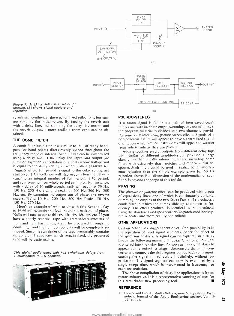
CONTROL
INPUT >-
Figure 7. At (A) a delay line setup for phasing. (B) shows signal capture and repetition.
reverb unit synthesizes these generalized reflections, but can- not simulate the initial return. By feeding the reverb unit with a delay line, and summing the delay line output and the reverb output, a more realistic room echo can he ob- tained.
THE COMB FILTER
A comb filter has a response similar to that of many band - pass (or band reject) filters evenly spaced throughout the frequency range of interest. Such a filter can be synthesized using a delay line. If the delay line input and output are summed together, cancellation of signals whose half -period is equal to the delay setting is accomplished (FIGURE 6). (Signals whose full period is equal to the delay setting are reinforced.) Cancellation will also occur when the delay is equal to an integral number of full periods + 1/2 period. and reinforcement on whole period multiples. For instance, with a delay of 10 milliseconds, nulls will occur at 50 Hz, 150 Hz, 250 Hz, etc., and peaks at 100 Hz. 200 Hz. 300 Hz, etc. By summing the output out of phase, the reverse occurs; Nulls, 10 Hz, 200 Hz, 300 Hz; Peaks; 50 Hz, 150 Hz, 250 Hz.
Here's an example of what to do with this. Set the delay to 16.66 milliseconds and feed the output back out of phase. Nulls will now occur at 60 Hz, 120 Hz. 180 Hz, etc. If you have a poorly recorded tape with tremendous amounts of hum and hum harmonics, it can be processed through the comb filter and the hum components will be completely re- moved. Since the remainder of the tape presumably contains no coherent frequencies which remain fixed, the processed tape will be quite usable.
This digital audio delay unit has switchable delays from 1 millisecond to 2.5 seconds.
INPUT SECTION
SOLID STATE
SWITCH b -o
(A)
SHIFT REGISTER
i
RECIRCULATE CONTROL
OUTPUT SECTION
PHASED OUTPUT
--rÿOUTPUT
(6)
TRIGGER'
PSEUDO- STEREO
If a mono signal is fed into a pair of interleaved comb filters (one with in -phase output summing, one out of phase), the program material is divided into two channels, provid- ing some very interesting pseudo- stereo effects. Signals of a
non- coherent nature will appear to have a centralized spatial orientation while pitched instruments will appear to wander from side to side as they are played.
Adding together several outputs from different delay taps with similar or different amplitudes can produce a large class of mathematically interesting filters, including comb filters with extremely sharp notches and otherwise flat re- sponse. Such filters could be used to realize better interfer- ence rejection than the simple example given for 60 Hz rejection above. Full discussion of the mathematics of such filters is beyond the scope of this article.
PHASING
The phasing or flanging effect can be produced with a pair of equal delay lines, one of which is continuously variable. Summing the outputs of the two lines (FIGURE 7) produces a
comb filter in which the combs slide up and down in fre- quency. The effect produced is identical to that produced using the standard two -tape- recorder -32- patch -cord hookup, hut is neater and more readily controllable.
OTHE APPLICATIONS
Certain other uses suggest themselves. One possibility is in the repetition of brief signal segments. either for effect or for spectrum analysis. A signal can be captured in a delay line in the following manner. (FIGURE 7, bottom). A signal is entered into the delay line. As soon as this signal starts to appear at the output, a trigger disconnects the input con- verter and connects the shift register output back to its input, causing the signal to recirculate indefinitely, without de- gradation. The signal segment can now be examined by a
single swept filter, which is incremented in frequency for each recirculation.
The above compilation of delay line applications is by no means exhaustive. It is a representative sampling of uses for this remarkable new processing tool.
REFERENCE
1. Blesser and Lee, An Audio Delay System Using Digital Tech- nology. Journal of the Audio Engineering Society, Vol. 19 #5, p. 393.
www.americanradiohistory.com
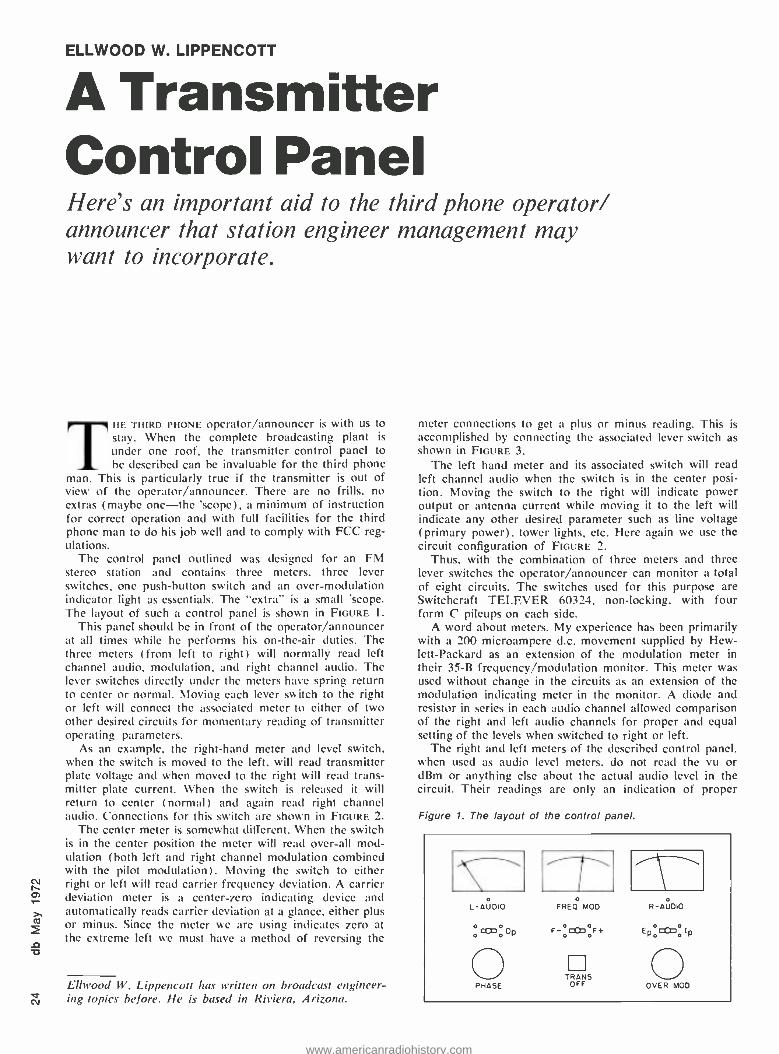
ELLWOOD W. LIPPENCOTT
A Transmitter Control Panel Here's an important aid to the third phone operator/ announcer that station engineer management may want to incorporate.
THE THIRD PHONE operator /announcer is with us to stay. When the complete broadcasting plant is
under one roof, the transmitter control panel to be described can be invaluable for the third phone
man. This is particularly true if the transmitter is out of view of the operator /announcer. There are no frills, no extras (maybe one -the 'scope), a minimum of instruction for correct operation and with full facilities for the third phone man to do his job well and to comply with FCC reg- ulations.
The control panel outlined was designed for an FM stereo station and contains three meters, three lever switches, one push -button switch and an over -modulation indicator light as essentials. The "extra" is a small 'scope. The layout of such a control panel is shown in FIGURE 1.
This panel should be in front of the operator /announcer at all times while he performs his on -the -air duties. The three meters (from left to right) will normally read left channel audio. modulation. and right channel audio. The lever switches directly under the meters have spring return to center or normal. Moving each lever switch to the right or left will connect the associated meter to either of two other desired circuits for momentary reading of transmitter operating parameters.
As an example, the right -hand meter and level switch, when the switch is moved to the left, will read transmitter plate voltage and when moved to the right will read trans- mitter plate current. When the switch is released it will return to center (normal) and again read right channel audio. Connections for this switch are shown in FIGURE 2.
The center meter is somewhat different. When the switch is in the center position the meter will read over -all mod- ulation (both left and right channel modulation combined with the pilot modulation). Moving the switch to either right or left will read carrier frequency deviation. A carrier deviation meter is a center -zero indicating device and automatically reads carrier deviation at a glance, either plus or minus. Since the meter we are using indicates zero at the extreme left we must have a method of reversing the
Ellwood W. Lippencolt has written on broadcast engineer- ing topics before. He is based in Riviera, Arizona.
meter connections to get a plus or minus reading. This is accomplished by connecting the associated lever switch as shown in FIGURE 3.
The left hand meter and its associated switch will read left channel audio when the switch is in the center posi- tion. Moving the switch to the right will indicate power output or antenna current while moving it to the left will indicate any other desired parameter such as line voltage (primary power). tower lights, etc. Here again we use the circuit configuration of FIGURE 2.
Thus. with the combination of three meters and three lever switches the operator /announcer can monitor a total of eight circuits. The switches used for this purpose are Switchcraft TELEVER 60324, non -locking, with four form C pileups on each side.
A word about meters. My experience has been primarily with a 200 microampere d.c. movement supplied by Hew- lett- Packard as an extension of the modulation meter in their 35 -B frequency/modulation monitor. This meter was used without change in the circuits as an extension of the modulation indicating meter in the monitor. A diode and resistor in series in each audio channel allowed comparison of the right and left audio channels for proper and equal setting of the levels when switched to right or left.
The right and left meters of the described control panel. when used as audio level meters, do not read the vu or dBm or anything else about the actual audio level in the circuit. Their readings are only an indication of proper
Figure 1. The layout of the control panel.
o L -AUDIO FREO MOD
oconoOp
PHASE
R-AJDiO
F-pc00oF+ EPoc0a)oIP
TRANS OFF OVER MOD
www.americanradiohistory.com
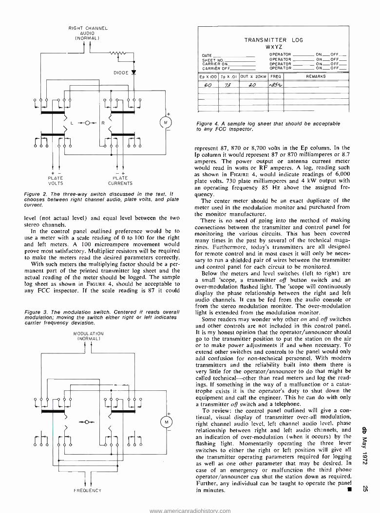
RIGHT CHANNEL AUDIO
(NORMAL)
+ - PLATE VOLTS
-+ PLATE
CURRENTS
Figure 2. The three -way switch discussed in the text. It chooses between right channel audio, plate volts, and plate current.
level (not actual level) and equal level between the two stereo channels.
In the control panel outlined preference would be to use a meter with a scale reading of 0 to 100 for the right and left meters. A 100 microampere movement would prove most satisfactory. Multiplier resistors will be required to make the meters read the desired parameters correctly.
With such meters the multiplying factor should be a per- manent part of the printed transmitter log sheet and the actual reading of the meter should be logged. The sample log sheet as shown in FIGURE 4, should be acceptable to any FCC inspector. If the scale reading is 87 it could
Figure 3. The modulation switch. Centered it reads overall modulation; moving the switch either right or left indicates carrier frequency deviation.
MODULATION (NORMAL)
11
rh -o o d1
FREOUENCr
TRANSMITTER WXYZ
DATE OPERATOR OPERATOR OPERATOR OPERATOR
LOG
ON OFF
SHEET CARRIER CARRIER
NO. ON OFF ON ON OFF_ OFF ON OFF_
Ep X 100 tp X .01 OUT X . 20KW FRB) REMARKS
60 73 do .B.f2
Figure 4. A sample log sheet that should be acceptable to any FCC inspector.
represent 87, 870 or 8,700 volts in the Ep column. In the Ip column it would represent 87 or 870 milliamperes or 8.7 amperes. The power output or antenna current meter would read in watts or RF amperes. A log, reading such as shown in FIGURE 4, would indicate readings of 6,000 plate volts, 730 plate milliamperes and 4 kW output with an operating frequency 85 Hz above the assigned fre- quency.
The center meter should be an exact duplicate of the meter used in the modulation monitor and purchased from the monitor manufacturer.
There is no need of going into the method of making connections between the transmitter and control panel for monitoring the various circuits. This has been covered many times in the past by several of the technical maga- zines. Furthermore, today's transmitters are all designed for remote control and in most cases it will only be neces- sary to run a shielded pair of wires between the transmitter and control panel for each circuit to be monitored.
Below the meters and level switches (left to right) are a small 'scope, a transmitter off button switch and an over- modulation flashed light. The 'scope will continuously display the phase relationship between the right and left audio channels. It can be fed from the audio console or from the stereo modulation monitor. The over -modulation light is extended from the modulation monitor.
Some readers may wonder why other on and off switches and other controls are not included in this control panel. It is my honest opinion that the operator /announcer should go to the transmitter position to put the station on the air or to make power adjustments if and when necessary. To extend other switches and controls to the panel would only add confusion for non -technical personnel. With modern transmitters and the reliability built into them there is
very little for the operator /announcer to do that might be called technical -other than read meters and log the read- ings. If something in the way of a malfunction or a catas- trophe exists it is the operator's duty to shut down the equipment and call the engineer. This he can do with only a transmitter oft switch and a telephone.
To review: the control panel outlined will give a con- tinual, visual display of transmitter over -all modulation, right channel audio level, left channel audio level, phase relationship between right and left audio channels, and an indication of over- modulation (when it occurs) by the flashing light. Momentarily operating the three lever switches to either the right or left position will give all the transmitter operating parameters required for logging as well as one other parameter that may be desired. In case of an emergency or malfunction the third phone operator /announcer can shut the station down as required. Further, any individual can be taught to operate the panel in minutes.
www.americanradiohistory.com
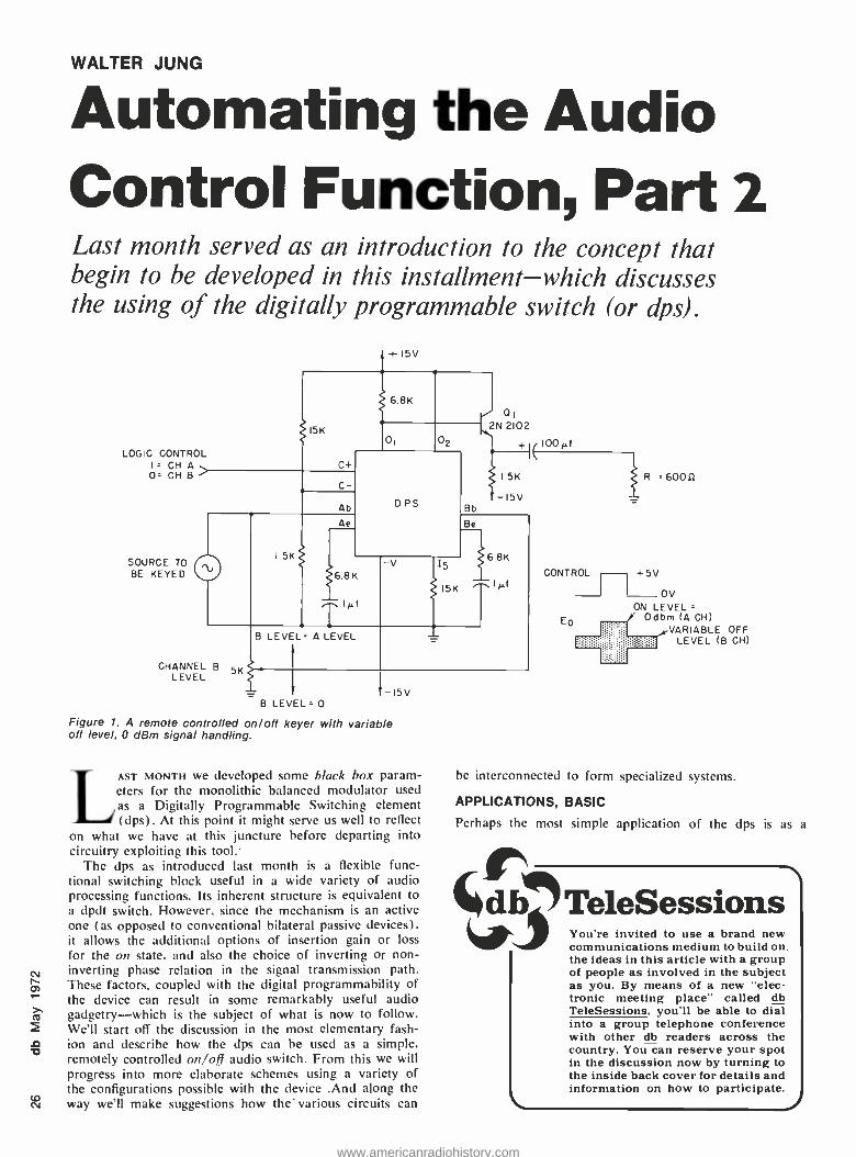
WALTER JUNG
Automating the Audio Control Function, Part 2 Last month served as an introduction to the concept that begin to be developed in this installment -which discusses the using of the digitally programmable switch (or dps).
LOGIC CONTROL I. CH A
Or CH B
SOURCE TO BE KEYED
CHANNEL B 5K LEVEL
Figure 1. A remote controlled on /off keyer with variable oft level, 0 dBm signal handling.
LAST MONTH we developed some black box param- eters for the monolithic balanced modulator used as a Digitally Programmable Switching element (dps). At this point it might serve us well to reflect
on what we have at this juncture before departing into circuitry exploiting this tool.
The dps as introduced last month is a flexible func- tional switching block useful in a wide variety of audio processing functions. Its inherent structure is equivalent to a dpdt switch. However, since the mechanism is an active one (as opposed to conventional bilateral passive devices). it allows the additional options of insertion gain or loss for the on state, and also the choice of inverting or non - inverting phase relation in the signal transmission path. These factors, coupled with the digital programmability of the device can result in some remarkably useful audio gadgetry -which is the subject of what is now to follow. We'll start off the discussion in the most elementary fash- ion and describe how the dps can be used as a simple. remotely controlled on/oft audio switch. From this we will progress into more elaborate schemes using a variety of the configurations possible with the device .And along the way we'll make suggestions how the' various circuits can
R =60011
CONTROL I
+5V J OV ON LEVEL
Odbm (A CH) VARIABLE OFF
LEVEL (B CH)
Eo
be interconnected to form specialized systems.
APPLICATIONS, BASIC
Perhaps the most simple application of the dps is as
ir db TeleSessions You're invited to use a brand new communications medium to build on the ideas in this article with a group of people as involved in the subject as you. By means of a new "elec- tronic meeting place' called db TeleSessions, you'll be able to dial into a group telephone conference with other db readers across the country. You can reserve your spot in the discussion now by turning to the inside back cover for details and information on how to participate.
www.americanradiohistory.com

Takeoff yours oes.
Hit the deck in shorts and a tee shirt. Or your bikini if you want. You're on a leisurely cruise to remote islands. With names like Martinique, Grenada, Guadeloupe. Those are the ones you've heard of.
A big, beautiful sailing vessel glides from one breathtaking Caribbean jewel to another. And you're aboard, having the time of your life with an intimate group of lively, fun - loving people. Singles and couples, too. There's good food, "grog" and a few pleasant comforts...but there's little resemblance to a stay at a fancy hotel, and you'll be happy about that. Spend ten days exploring paradise and getting to know congenial people. There's no other vacation like it.
Your share from S245. A new cruise is forming now. Write Cap'n Mike for your free adventure
booklet in full color.
OWindjammer Cruises.
P O. Box 120. Dept Miami Brach. Florida 3.3139 N V
www.americanradiohistory.com
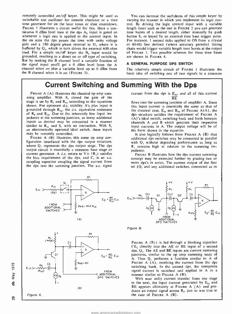
CO N
remotely controlled on/off keyer. This might be used as switchable test oscillator for console checkout or a time tone generator for on the hour tones or slate countdown. FIGURE 1 illustrates a circuit useful for this. Here a con- tinuous 0 dBm level tone at the dps Al, input is gated on whenever a logic one is applied to the control input. In the on state the dps passes the tone with unity voltage gain and a 180 degree phase reversal to O, where it is buffered by Q, which in turn drives the external 600 -ohm load. For a simple on /off keyer the B,, input would be grounded, resulting in a direct on or off type of switching. But by making the B channel level a variable fraction of the signal input you'll get a 0 dBm level from the A channel when on plus a variable level up to 0 dBm from the B channel when it is on (FIGURE 3).
You can increase the usefulness of this simple keyer by varying the manner in which you implement its logic con- trol. By driving the logic control input with a variable length timer such as the one in FIGURE 2 you can generate tone bursts of a desired length, either manually by push button S, or keyed by an external time base trigger pulse. For instance, 1 second ticks applied to OS from a crystal or 60 -Hz line derived (where accuracy permits) timing chain would trigger variable length tone bursts at the output of FIGURE 1. Two possible schemes for these time bases are shown in FIGURE 4.
A GENERAL PURPOSE DPS SWITCH
The relatively simple circuit of FIGURE 1 illustrates the basic idea of switching one of two signals to a common
Current Switching and Summing With the Dps FIGURE A (A) illustrates the classical op -amp sum-
ming amplifier. With S, closed the gain of the stage is set by Rf and R,,, according to the equations shown. For optimum d.c. stability A's plus input is grounded through R,,,, the d.c. equivalent resistance of Rf and R,11. Due to the inherently low input im- pedance at the summing junction, as many additional inputs as desired may be connected in a manner similar to R,,, and S, with no interaction. With S, an electronically operated ideal switch, these inputs may be remotely controlled.
FIGURE A (B) illustrates this same op amp con- figuration interfaced with the dps output structure, where Q, represents the dps output stage. The dps output circuit is essentially a common base stage or current generator. A d.c. return to V+ (R,) satisfies the bias requirement of the dps, and C,. is an a.c. coupling capacitor coupling the signal current from the dps into the summing junction. The a.c. signal
SI R,n r--
Ein (RE) L_-J
FROM ADDITIONAL SWITCHES
RL 15K)
RE CE E1n
(R1n)
Figure A.
Rf
NMI
Cc
QI
r
ReQ : Rf//Rln
(A)
Rf
Reo =Rf
(B)
E0 -RmnE1n
-Rf E0: RE Em
FROM ADDITIONAL
DPS SWITCHES
current from the dps is E,,,, and all of this current RE
flows into the summing junction of amplifier A. Since this input current is essentially the same as that of the classical case, E,,, and R, of FIGURE A(A), the dps structure satisfies the requirement of FIGURE A (A)'s ideal switch, switching back and forth between channels A and B which generate their respective input currents in A. The output voltage will be of the form shown in the equation.
It also logically follows from FIGURE A (B) that additional dps switches may be connected in parallel with Q, without degrading performance as long as
R, remains high in relation to the summing im- pedance.
FIGURE B illustrates how the dps current summing concept may be extended further by placing two or more dps's in series. The current output of the first set (Q, and any additional switches, connected as in
RE CEI
E1 n i- --'VsAr)
Figure B.
QI
+V t+V
RL
CE2 02
FROM I -V
ADDIT ONAL DPS SWITCHES
RL
Cc
ReQ
Rf
EO RE Ein
FIGURE A (B)) is fed through a blocking capacitor CE, directly into the AE or BE input of a second dps, Q,. The AE and BE inputs are current summing junctions, similar to the op amp summing node of A. Thus Q., performs a function similar to A of FIGURE A (A), receiving the current from the dps switching hank. In the second dps, the composite signal current is switched and applied to A in a
manner similar to FIGURE A (B). With near unity current transfer from one stage
to the next, the input current generated by E,,, and RE appears ultimately at FIGURE A (A) and pro- duces an output signal across R f, just as was true in the case of FIGURE A (B).
www.americanradiohistory.com
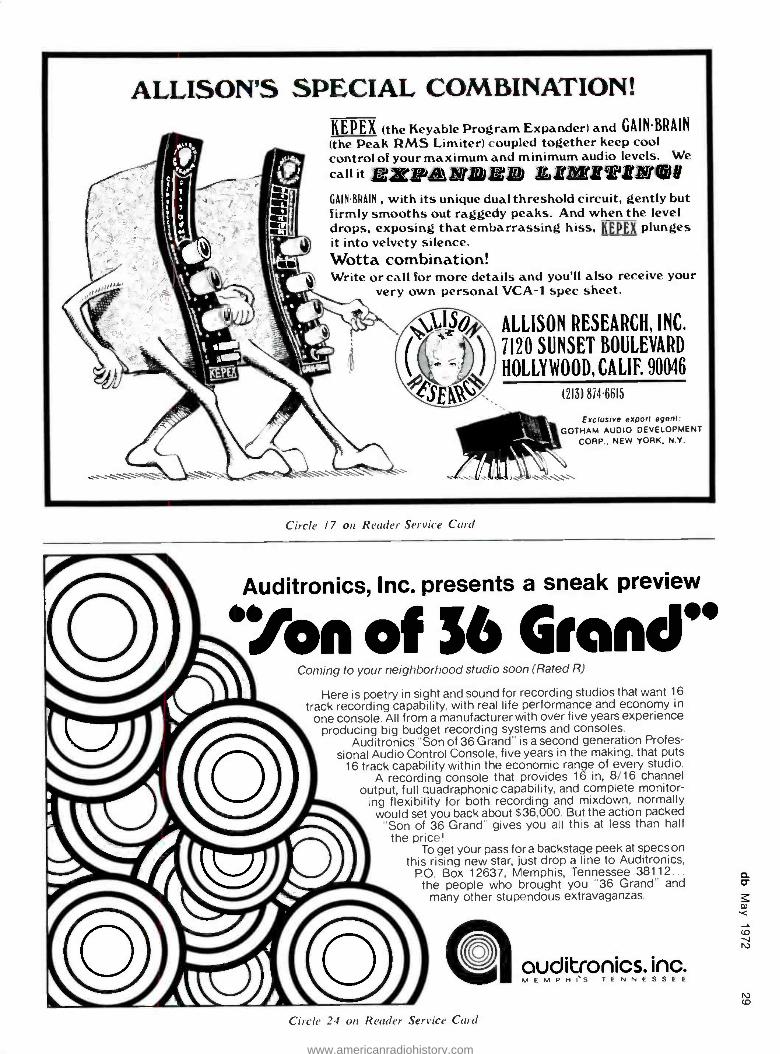
ALLISON'S SPECIAL COMBINATION! KEPEX (the Heyable Program Expander) and GAINBRAIN (the Peak RMS Limiter) coupled together keep cool control of your maximum and minimum audio levels. We call it Ez ja JBJ Li iiT'ENta GAINBRAIN , with its unique dual threshold circuit, gently but firmly smooths out raggedy peaks. And when the level drops, exposing that embarrassing hiss, KEPEX plunges it into velvety silence. Wotta combination! Write or call for more details and you'll also receive your
very own personal VCA -1 spec sheet.
ALLISON RESEARCH, INC.
7120 SUNSET BOULEVARD
HOLLYWOOD, CALIF. 90046
(213) 874.6615
Exclusive export agent: GOTHAM AUDIO DEVELOPMENT
CORP., NEW YORK. N.Y.
Circle 17 on Reader Service Card
Auditronics, Inc. presents a sneak preview
.'Yon of 56 Gran" Coming to your neighborhood studio soon (Rated R)
Here is poetry in sight and sound for recording studios that want 16 track recording capability, with real life performance and economy in
one console. All from a manufacturer with over five years experience producing big budget recording systems and consoles.
Auditronics "Son of 36 Grand" is a second generation Profes- sional Audio Control Console, five years in the making, that puts
16 track capability within the economic range of every studio. A recording console that provides 16 in, 8/16 channel
output, full quadraphonic capability, and complete monitor- ing flexibility for both recording and mixdown, normally would set you back about $36,000. But the action packed
"Son of 36 Grand" gives you all this at less than half the price!
To get your pass for a backstage peek at specs on this rising new star, just drop a line to Auditronics,
P.O. Box 12637, Memphis, Tennessee 38112... the people who brought you "36 Grand" and
many other stupendous extravaganzas.
O Quditronics. inc.
Circle 24 on Reader Service Card
M E M P M IsS T E N N E S S E E
www.americanradiohistory.com
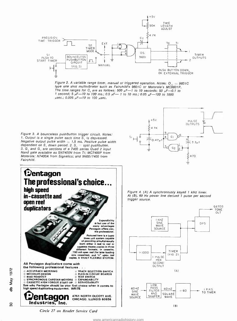
PRECISION TIME TRIGGER
SI PUSH TO
START TIMER
TIME 50K LENGTH
ADJUST
S2 TIMER MODE
BOUNCELESS PUSHBUTTON
CIRCUIT (FIG.3)
TO
J TIMER
OUTPUTS 2
PUSH BUTTON DOWN, OH EXTERNAL TRIGGER
Figure 2. A variable range timer, manual or triggered operation. Notes: O _- 9601C type one shot multivibrator such as Fairchild's 9601C or Motorola's MC8601P. The time ranges for C, are as follows: 500 uF -1 to 10 seconds; 50 .F-0.1 to 1 second; 5 .F-10 to 100 ms.; 0.5 uF- 1 to 10 ms.; 0.05 uF -100 to 1000 usec.; 0.005 MF -10 to 100 ysec.
Figure 3. A bounceless pushbutton trigger circuit. Notes: 1. Output is a single pulse each time S, is depressed. Negative output pulse width _ 1.5 ms. Positive pulse width dependent on S, down period. 2. S, spst pushbutton. 3. G, and G. are sections of a 7400 series Quad 2 input Nand gate available as SN7400N from TI; MC7400P from Motorola; N7400A from Signetics; and 9N00/7400 from Fairchild.
pentagon The professional's choice... high speed in- cassette and open reel duplicators
Espandibility is but one of the
many advantages Pentagon offers you,
the professional.
Pictured here is a basic three unit system capable
of providing simultaneously from either a reel to reel or
cassette master, copies in three different formats; in cassette.
.150 mil open reel (for later loading into cassettes). and V." open reel
copies. A TRULY FLEXIBLE SYSTEM.
All Pentagon duplicators come with the following professional features . . .
ACCUTRACK METERING MODULAR DESIGN
u BIAS READOUT u SYNCHRONOUS CAPSTAN MOTORS
CASSETTE HIGH TORQUE START -UP
TRACK SELECTION SWITCH PLUG -IN CIRCUIT BOARDS TEST SWITCH EXPANDABILITY SERVICEABILITY
See why Pentagon should be your fir t choice when it comes to high speed duplicating equipment. WRITE
entagon CHICAGO, 6 656 Industries, Inc.
Circle 27 on Reader Service Card
PULSE -I- OUTPUTS
r- J
Figure 4. (A) A synchronously keyed 1 kHz timer. At (B), 60 Hz power line derived 1 pulse per second trigger source.
KHZ SINE
WAVE SOURCE
1000
60 HZ SINE WAVE
SOURCE
I PULSE PER
SECOND OUTPUT
LOW PASS
FILTER AND
SHAPER
TIMER (FIG 2)
(A)
60 HZ
SQUARE WAVE
(B)
60
DPS
GATED TONE OUT
IPPS TO TIMER
www.americanradiohistory.com
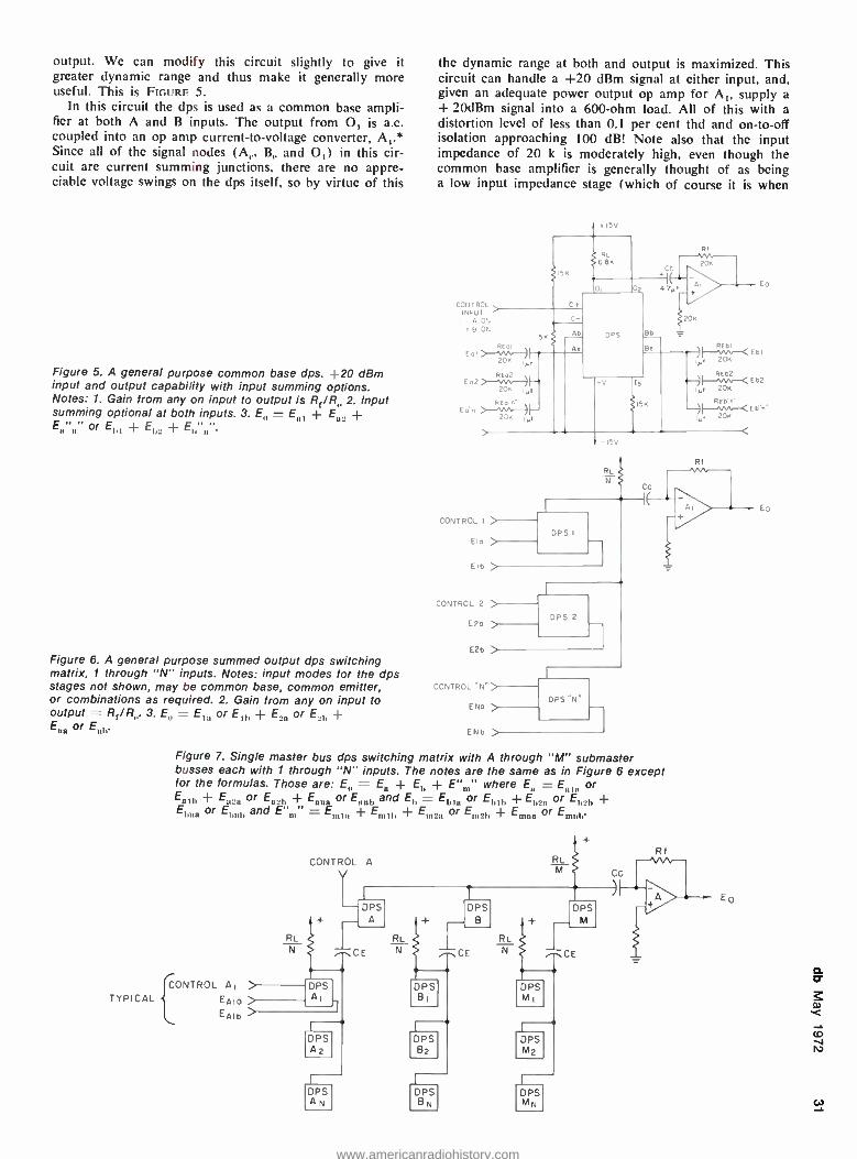
output. We can modify this circuit slightly to give it greater dynamic range and thus make it generally more useful. This is FIGURE 5.
In this circuit the dps is used as a common base ampli- fier at both A and B inputs. The output from 0, is a.c. coupled into an op amp current -to- voltage converter, A,.* Since all of the signal nodes (A,., B,. and 0,) in this cir- cuit are current summing junctions, there are no appre- ciable voltage swings on the dps itself, so by virtue of this
Figure 5. A general purpose common base dps. +20 dBm input and output capability with input summing options. Notes: 1. Gain from any on input to output is RE /R 2. Input summing optional at both inputs. 3. EI, = E,,, + E_ + E"" or EII, + + E,,"".
Figure 6. A general purpose summed output dps switching matrix, 1 through "N" inputs. Notes: input modes for the dps stages not shown, may be common base, common emitter, or combinations as required. 2. Gain from any on input to output = Rr /R,,. 3. En = E,,, or E,,, + E._, or E._,, + E, or E,,,;
TYPICAL
the dynamic range at both and output is maximized. This circuit can handle a +20 dBm signal at either input, and, given an adequate power output op amp for A,, supply a
+ 20dBm signal into a 600 -ohm load. All of this with a distortion level of less than 0.1 per cent the and on -to -off isolation approaching 100 dB! Note also that the input impedance of 20 k is moderately high, even though the common base amplifier is generally thought of as being a low input impedance stage (which of course it is when
CONTRCL INPUT
A ON B ON
+15 V
REO2
20K R,
-ISV
RL
CONTROL I >
Elo
Eib >
CONTROL 2
DPS I
Ego - E2D >
CONTROL "N ")
DPS 2
ENO
END
DP5 "N"
RI
Figure 7. Single master bus dps switching matrix with A through "M" submaster busses each with 1 through "N" inputs. The notes are the same as in Figure 6 except for the formulas. Those are: E,, = E, + E,, + E " where E = E,,,, or E ,D + E _ or E,_,, + En or E and E,, = E,,, or E,,,,, +E,r_ or E,reb + E, or E,,,,, and E "m" = Em, + Em7L + E or Em21, + Em,,, or Emni,
CONTROL AI
EAIO
EAIb
CONTROL A RI
DPS BI
L DPS 82
D PS BN
E3
W
www.americanradiohistory.com
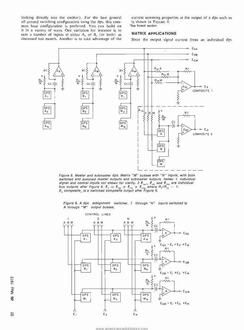
looking directly into the emitter). For the best general all around switching configuration using the dps. this com- mon hase configuration is preferred. You can build on it in a variety of ways. One variation for instance is to sum a number of inputs at either A,. or B,. (or both) as
discussed last month. Another is to take advantage of the
current summing properties at the output of a dps such as
is shown in FIGURE 6. 'See boxed section
MATRIX APPLICATIONS
Since the output signal current from an individual dps
Rf+
RL
N Cc
DPS AI
DPS A2
DPS AN
AA +
Rf
+
RL
N CC
DPS B
DPS B2
DPS BN
- + Rf
RIN
Rin Rf
+
RL M
DPS A
DPS B
(
DPS M
CC
Rf
EPA
EOB
EOM
E0
COMPOSITE I
EO
COMPOSITE 2
Figure 8. Master and submaster dps. Matrix "M" busses with "N" inputs, with both switched and summed master outputs and submaster outputs. Notes: 1. Individual signal and control inputs not shown for clarity. 2 E E,,,, and E,,,,, are individual bus outputs after Figure 5. E = E + E b E where Rt./ R, 1.
E composite, is a switched composite output after Figure 6.
Figure 9. A dps assignment switcher. 1 through "N inputs switched to A through "M" output busses.
A B M
V V V
CONTROL LINES
2 N
A B M A B M VVV VVV
RL
DPS AI
DPS A2
DPS B2
DPS AN
RL
DPS MI
n n E E2
DPS
M2
DPS BN
RL
DPS MN
A EN
Rf
EPA
EPA = El +E2 +EM Rf
EOB
E09 ' El +E2 +EM
Rf
EOM
EOM = E, +E2 +EM
www.americanradiohistory.com
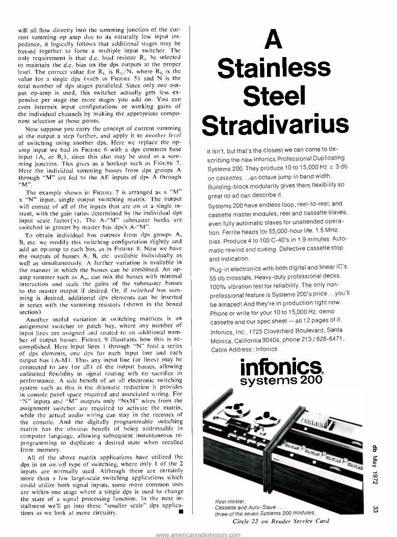
will all flow directly into the summing junction of the cur- rent summing op amp due to its naturally low input im- pedance, it logically follows that additional stages may be
bussed together to form a multiple input switcher. The only requirement is that d.c. load resistor Ri, be selected
to maintain the d.c. bias on the dps outputs at the proper level. The correct value for 111, is R1 /N, where RI, is the value for a single dps (such as FIGURE 5) and N is the total number of dps stages paralleled. Since only one out- put op -amp is used, this switcher actually gets less ex-
pensive per stage the more stages you add on. You can even intermix input configurations or working gains of the individual channels by making the appropriate compo- nent selection at those points.
Now suppose you carry the concept of current summing at the output a step further, and apply it to another level of switching using another dps. Here we replace the op- amp input we had in FIGURE 6 with a dps common base
input (A,. or B,.), since this also may be used as a sum- ming junction. This gives us a hookup such as FIGURE 7.
Here the individual summing busses from dps groups A through "M" are fed to the AE inputs of dps A through "M
The example shown in FIGURE 7 is arranged as a "M" x "N" input, single output switching matrix. The output will consist of all of the inputs that are on at a single in- stant, with the gain ratios determined by the individual dps input scale factor(s). The A -"M" submaster banks are switched in groups by master bus dps's A - "M ".
To obtain individual bus outputs from dps groups A, B, etc. we modify this switching configuration slightly and add an op -amp to each bus, as in FIGURE 8. Now we have the outputs of busses A. B, etc. available individually as
well as simultaneously. A further variation is available in
the manner in which the busses can be combined. An op- amp summer such as As, can mix the busses with minimal interaction and scale the gains of the submaster busses
to the master output if desired. Or, if switched bus sum-
ming is desired, additional dps elements can be inserted in series with the summing resistors (shown in the boxed section) .
Another useful variation in switching matrices is an
assignment switcher or patch bay, where any number of input lines are assigned and routed to an additional num- ber of output busses. FIGURE 9 illustrates how this is ac-
complished. Here input lines I through "N" feed a series
of dps elements, one dps for each input line and each output bus (A -M). Thus any input line (or lines) may be
connected to any (or all) of the output busses, allowing unlimited flexibility in signal routing wth no sacrifice in performance. A side benefit of an all electronic switching system such as this is the dramatic reduction it provides in console panel space required and associated wiring. For "N" inputs and "M" outputs only "NxM" wires from the assignment switcher are required to activate the matrix, while the actual audio wiring can stay in the recesses of the console. And the digitally programmable switching matrix has the obvious benefit of being addressable in computer language, allowing subsequent instantaneous re- programming to duplicate a desired state when recalled from memory.
All of the above matrix applications have utilized the
dps in an on /off type of switching, where only I of the 2
inputs are normally used. Although there are certainly more than a few large -scale switching applications which could utilize both signal inputs, some more common uses
are within one stage where a single dps is used to change the state of a signal processing function. In the next in- stallment we'll go into these "smaller scale" dps applica- tions as we look at more circuitry.
A Stainless
Steel Stradivarius
it isn't, but that's the closest we can come to de-
scribing the new Infonics Professional Duplicating
Systems 200. They produce 10 to 15,000 Hz ± 3 db
on cassettes... an octave jump in band width.
Building -block modularity gives them flexibility so
great no ad can describe it.
Systems 200 have endless loop, reel -to -reel, and
cassette master modules, reel and cassette slaves,
even fully automatic slaves for unattended opera-
tion. Ferrite heads for 55,000 -hour life. 1.5 MHz.
bias. Produce 4 to 100 C -40's in 1.9 minutes. Auto-
matic rewind and cueing. Defective cassette stop
and indication.
Plug -in electronics with both digital and linear IC's.
55 db crosstalk. Heavy -duty professional decks.
100% vibration test for reliability. The only non-
professional feature is Systems 200's price...you'll
be amazed! And they're in production right now.
Phone or write for your 10 to 15,000 Hz. demo
cassette and our spec sheet - all 12 pages of it.
Infonics, Inc., 1723 Cloverfield Boulevard, Santa
Monica, California 90404, phone 213 / 828 -6471,
Cable Address: Infonics
infonics systems 200
Reel master, Cassette and Auto -Slave .. .
three of the seven Systems 200 modules.
Circle 22 on Reader Service Card
w
www.americanradiohistory.com
v M
Martin Dickstein
SOUND WITH IMAGES
Ever wonder, while watching a football or baseball game, how some small piece of the action that hap- pened just a few seconds ago can be shown again, and at full speed or still frame or any speed in between? Sure, it's instant replay, but perhaps you might be interested in a few of the details of the system that costs about $100,000 per unit.
Back in 1967, only 5 years ago, Ampex developed this special device that has since been bought by broad- cast networks, local stations, com- mercial production houses, and other establishments that could afford the unit to the total tune of more than
Electronics Engineer
Automated Processes, Inc. requires an imaginative and in- ventive circuit designer for new product development. Must have a working knowl- edge of audio circuitry and re- lated analog and digital tech- niques. Full benefits. Excellent salary. Contact Saul Walker, v.p. engineering.
AUTOMATED PROCESSES, INC_
80 MARCUS DRIVE, MELVILLE, NEW YORK 11746
516- 694 -9111
Instant Replay
$10,000,000. At first thought, it would seem that this company, which is so deeply involved in the tape field, would have come up with a tape unit for the instant replay device, but it turns out that this was not the way to go at all.
One of the capabilities built into tape recorders, video or audio, pro- vides the user with a means to proceed quickly to a portion of the recording anwhere in the tape. This allows play- ing any part of the tape whether it is
ahead or behind the point at which the tape has been stopped. Getting to the spot which is to be replayed, how- ever, is the trick. On a video tape recorder, it may seem like the rewind and fast forward might be really fast, but it takes longer, and is not as ac- curate as is demanded by the require- ments of broadcasting networks or sta- tions where replaying a scene quickly is "instant" replay. This means intro- ducing the replay, cuing up the action desired, playing the scene (at slow, normal or inbetween speeds or with mixed speeds and even freeze -frame) all in a time out or before the next play starts. That has to be "instant," not just quick replay. As good as tape is for many applications, in this case a new method had to be devised.
The process was developed using a
magnetic disc. Hi -fi fans know how quickly and easily they can move a
pickup head to any part of the disc and how simply they can replay a por- tion of the record they had just heard. It is this same flexibility which is used in the magnetic disc system with several obvious advantages. Since there is no cutting into the surface of the disc, the same one can be used many, many times without deteriora- tion of signal. Also, the magnetic disc has the advantage of magnetic tape in that there is no processing necessary to regain the information put on the surface, as with an audio disc. Other advantages of the magnetic disc over other media, even magnetic tape, are fewer drop outs than tape, longer life, steadier picture, and the ability to play in reverse at any speed, immediately after recording the desired material.
The disc is made of aluminum and is optically smooth and flat. Then the
magnetic material is added. This is a thin layer of a magnetic cobalt alloy which is electroplated on. To protect this surface, a layer of rhodium, a few micro -inches thick, is plated on. The mirror -like surface is now pro- tected against corrosion and permits smooth movement of the magnetic head across the disc.
Before discussing the operation of the disc system, it might be well to see how an instant replay is produced for a broadcast. More than one unit is used when possible in order to al- low for complete coverage and flexi- bility of operation. Each of the record units can be fed from any of the cameras, usually on a preset basis. As the action takes place, the director of the show can select which camera will be recorded by which machine and in most cases, the experienced di- rector can anticipate the course the action will take. A word on the inter- communicating headphone /mouthpiece to the replay unit operator and the repeat is ready to go. Each play is recorded at the different angles and perspectives of the cameras, and with three recorders at his disposal, the good director has the odds with him that the desired action will be there within seconds for repeat perform- ance. (This recording from the came- ras in no way has any effect on the camera output singals which are still being fed live to the viewing audience as the action is taking place in real time.)
There are primarily two problems associated with instant replay at slower- than -normal speed. For the image on the screen to be steady dur- ing slow- motion replay and for a com- plete picture to be seen, it is necessary to change only the speed at which the information is fed to the screen, but the scanning rate of lines, fields ,and frames must not be disturbed. In color transmission, it is similarly necessary to retain the original hues and not disturb the color demodulation process in the receiver at home. Thus, the video signal must still be at the nor- mal bandwidth, with the normal scan- ning rate and interlacing, and con- taining the proper color components in proper phase and amplitude even
www.americanradiohistory.com
though the picture is moving at slower than normal speed.
To see how these problems were overcome, consider first that a frame is made of two separate fields, in a 2 -to -I interlace system, the fields be- ing scanned individually 1 /60th of a second apart. The first field is scanned and is reproduced on the screen in alternate lines, leaving the in- between lines for the second scanning to fill in with the next field, thus making up a
full frame. Each field can, therefore, be considered to be displaced from the other by 1h line, the displacement of the horizontal sync pulse taking place during the horizontal blanking period. However, considering the ver- tical sync pulse interval, both fields are the same.
It might seem a simple matter to produce a slow- motion image by re- peating each frame a predetermined number of times. For example, if an image (one frame, or two fields) were repeated twice before the next image was projected onto the screen, this would show up as half -speed action. However, this type of reproduction provides very unsatisfactory results. This can be realized when considera- tion is given to the fact that a moving object is displaced a definite distance in the 1 /60th of a second between fields, and the faster the object is mov- ing the greater the displacement. When reproduced in slow motion, the effect would appear to be a double exposure on the picture screen. To avoid this distortion, it is necessary to repro- duce each frame made up artificially of two identical fields thus avoiding the displacement of moving objects in adjacent fields. To repeat the same field twice while retaining the normal 2/1 interlace pattern, it is necessary to introduce a half -line displacement into the second scan of the original field. Since the visual information in the two reproduced fields is the same, in- troduction of the half -line displace- ment provides a full frame, with pro- per interlace format, and without the distortion of movement.
With slow- motion reproduction of color, the problem is again related to fact that there are two scanned fields in each frame, but this time it is a
matter of proper phasing. In the first frame of the color image, the first field (odd lines) has each line begin with 0- degree phase. The second field (even lines) has each line begin with a chroma phase of 180 degrees. In the second frame, the first field has odd lines begin with a chroma phase of 180 degrees while the even lines of the second field begin with 0 degrees. Notice what happens when the slow - motion image is made up of repeats of just one field of each frame.
The first frame has the first field beginning with a chroma phase of 0- degrees. If this field is repeated (dis- placed by 1/2 line, of course), the in- terlacing lines of the second field of the new first (artificial) frame would also have the second line beginning with 0- degree chroma phase. The re- quirements of the properly reproduced image are that the adjacent lines be of opposite chroma phase. To accomplish this, a chroma phase inverter is intro- duced in the electronics of the system.
The inverter operates by removing the chroma information from the video signal, inverting its phase, and recombining it with the luminance portion of the signal. Proper color reproduction requirements are then satisfied.
The chroma inverter is activated during the even fields of the artificial frames of slow- motion replays, along with the half -line delay circuits. How- ever, during freeze -frame operation, the introduction of the delay and in- verter systems is slightly different. For still- framing, the first field has no de- lay and no chroma inversion. The second field has both delay and in- version. The third field (first field of the second frame) consists of a repeat of the first field again. Thus, the in- version must remain active while the delay must be removed. In the fourth field (second field of the second frame) the delay is again introduced but the inversion is removed as this is again a repeat of the same original field. Etc., etc., until the action starts again.
The disc recorder unit, at least the Ampex HS -100, utilizes four discs, 16 inches in diameter, mounted one above the other on a common rotat- ing shaft, spinning at 60 rev. /sec. The rotation speed is kept constant by a vertical sync reference signal. One complete revolution of the discs cor- responds, therefore, precisely to one image field. Each field begins and ends during the vertical blanking in- terval.
One head is provided for each sur- face of each disc. This allows four consecutive fields to be recorded (one by each head). Each head does its own erasing, recording and playing back. Each of the heads is mounted in such a manner as to be capable of being moved radially by a stepping motor independently of the other heads. Thus, during every four -frame operation of the system, each head is doing something independently of the other three.
Following the operation of each head sequence, the first head begins at the outside edge by recording the first field, during the first complete revolution of the discs. During the
second field, the first head moves one step toward the center of the disc. In the third field, the first head moves one more step toward the center. For the fourth revolution, the same head goes into the erase mode and wipes whatever might have been recorded previously in that track on the disc. This first head records the fifth field, two tracks away from the first field it recorded. This cycle is repeated for each sequence of five frames.
The second head, during the first field, erases what might have been put down previously in its first track. It then records the second field in this first track. During the third and fourth fields, the second head moves a step each time toward the center of the disc. It is now ready to repeat its previous cycle.
Head number three begins during the first field by moving a step and then erases its previously recorded ma- terial during the second field. It re- cords new material in this track during the third field and moves a step inward for the fourth field.
The sequence of the fourth head consists of two steps inward during the first and second fields, erasing during the third field and recording the fourth field. As each track is 7.5 mils wide and each move radially is a distance of 10 mils, it is simple to determine the distance center -to- center of the adjacent recorded tracks of each head, as they move toward the center.
When the heads have moved to- ward the disc's center and reach their farthest position, a sensing mechanism reverses their direction of motion and the heads continue their sequence while moving toward the outer edge of the discs. Recording is done in those tracks previously left open dur- ing the inward movement. The same reversal takes place again when the heads reach their outermost positions.
Playback is accomplished by turn- ing off the erase /record mode and switching to the playback mode as in tape units. Freeze -frame is achieved by arresting the radial movement of the heads at any point. Slow motion is accomplished by a combination of the freeze -frame operation and the normal speed. By reversing the mo- tion of the heads at any time, the action can be shown backwards.
All of this information refers pri- marily to a rather expensive unit which broadcasters used almost ex- clusively, but simpler and less ex- pensive units can be used for special effects by video production houses, for slow- motion study by industry and schools, and in many other applica- tions. Build -it- yourself kits for the home? Not yet! w v,
www.americanradiohistory.com
As a service to our readers we are pleased to otter books from prominent technical publishers. All prices listed are the publishers' net. Shipping charges are included.
To order use the coupon at the bottom of the page. Indicate quantity on the special instructions line
If more than one copy of a title is wanted. Full payment must accompany your order. We cannot ship c.o.d. Checks or money orders should be made payable to Sagamore Publishing Company, Inc. Because of the time required to process orders, allow several weeks for the receipt of books.
3n 20. The Audio Cyclopedia (2nd ed.). Dr. Howard M. Tremaine. New and updated, here is the complete audio reference li- brary in a single volume. It provides the most comprehensive information on every aspect of the audio art. This new edition includes the latest audio developments in- cluding the most recent solid -state systems and integrated circuits. It covers all sub- jects in the fields of acoustics, recording, and reproduction with more than 3400 re- lated topics. Each topic can be instantly located by a unique index and reference system. More than 1600 illustrations and schematics help make complicated topics masterpieces of clarity. 1760 pages; 61/2 x 9% hardbound. $29.95
1. The Technique of the Sound Studio. Alec Nisbett. This is a handbook on radio and recording techniques, but the princi- ples described are equally applicable to film and television sound. 264 pages; 60 diagrams; glossary; indexed; 51/2 x 81; clothbound. $14.50
7. Acoustical Tests and Measurements. Don Davis. Provides solid understanding of the entire subject of acoustical measure- ments; based on actual field test work, using commercial equipment. 192 pages; 51/2 x 81/2; hardbound. $6.95
8. Handbook of Electronic Tables & Formulas, (3rd edition). A one -stop source for all charts, tables, formulas, laws, sym- bols, and standards used in electronics. In- cludes an 8 -page, full -color fold -out chart showing latest FCC allocations for the en- tire frequency spectrum. 232 pages; 5'/2 x 81/2; hardbound. $5.50
Sagamore Publishing Company, Inc. 980 Old Country Road, Plainview, N.Y. 11803
Please send me the books I have circled below. My full remittance in the amount of $ is enclosed. N.Y. State resi- dents add 7% sales tax.
1 2 3 4 5 6 7 8 9 10 11
12 13 14 15 16 17 18 19 20 21 22 23 24 25 26 27 28 29 30 31 32 33 34 35 36 37 38 39 40
Name
Address
City
State Zip Special Instructions
Canada and foreign: Add $1.00 per book
24. Basic Electronic Instrument Handbook. Edited by Clyde F. Coombs, Jr. Hewlett - Packard Co. A basic reference background for all instruments. Offers saving in time and effort by having complete information in one volume on how to get the most bene- fit from available devices, how to buy the best instrument for specific needs. Reduces chances of costly errors. Ideal reference book, it is an excellent source for the be- ginner, technician, the non -electrical en- gineering man, or general non -engineering scientific and technical personnel. 800 pages. Hardbound. $19.50
25. Operational Amplifiers -Design and Applications. Burr -Brown Research Corp. A comprehensive new work devoted en- tirely to every aspect of selection, use, and design of op amps -from basic theory to specific applications. Circuit design tech- niques including i.c. op amps. Applica- tions cover linear and non -linear circuits, A/D conversion techniques, active filters, signal generation, modulation and de- modulation. Complete test circuits and methods. 474 pages. $15.00
26. The Design of Digital Systems. John B. Peatman. Textbook for students desiring to develop a creative approach design capa- bility through digital systems approach. Answers these question: Under what cir- cumstances it is desirable to implement a system digitally? What are some of the components available for implementing the system? How do we go about design- ing it? 448 pages. $15.50
31. Solid -State Electronics. Hibberd. A Basic Course for Engineers and Techni- cians. An extremely practical reference book for anyone who wants to acquire a good but general understanding of semi- conductor principles. Features questions and answers, problems to solve. 1968. 169 pp. $9.95
32. Circuit Design for Audio, AM /FM, and TV. Texas Instruments. Texas Instruments Electronics Series. Discusses the latest ad- vances in design and application which represent the results of several years re- search and development by TI communica- tions applications engineers. Emphasizes time- and cost -saving procedures. 1967. 352 pp. $14.50
35. An Alphabetical Guide to Motion Picture, Television, and Videotape Produc- tions. Levitan. This all- inclusive, authorita- tive, and profusely illustrated encyclopedia is a practical source of information about techniques of all kinds used for making and processing film and TV presentations. Gives full technical information on mate- rials and equipment, processes and tech- niques, lighting, color balance, special effects, animation procedures, lenses and filters, high -speed photography, etc: 1970. 480 pp. $24.50
40. Radio Transmitters. Gray and Graham. Provides, in a logical, easy -to- understand manner, a working knowledge of radio transmitters for quick solution of problems in operation and maintenance. 1961. 462 PP. $16.00
23. Wide Screen Cinema & Stereophonic Sound. M.Z. Wystozky. First published in USSR in 1965 this excellent English trans- lation covers wide gauge films, panoramic films, circular panoramic cinematography; technical fundamentals of stero sound re- cording for film, as well as details of the Soviet systems now in use. 284 pages.
$15.00
33. Noise Reduction. Beranek. Designed for the engineer with no special training in acoustics, this practical text on noise control treats the nature of sound and its measurement, fundamentals of noise con- trol, criteria, and case histories. Covers advanced topics in the field. 1960. 752 pp.
$19.50
27. Noise & Vibration Control. Edit. by Leo L. Beranek. Practical design and reg- ulatory information; formulas, choice of materials and structures, city codes and hearing protection; indispensable for de- sign engineers, public officials who prepare regulations for noise control, safety and environmental engineers involved in noise and vibration controls. Covers data analysis, transmission of sound, psychophysiological design criteria, hearing damage risk, etc: Wealth of detail, comprehensive index and concise appendices. 650 pages. $29.50
28. Environmental Acoustics. Leslie L. Doelle. Applied acoustics for those in envi- ronmental noise control who lack spe- cialized acoustical training. Basic informa- tion in comprehensible and practical form for solving straightforward problems. Ex- plains fundamental concepts; pure theory minimized. Practical applications stressed, acoustical properties of materials and con- struction listed, actual installations with photos and drawings. Appendixes illustrate details of 53 wall types and 32 floor plans and other useful data. 246 pgs. $18.50
21. Acoustics -Room Design and Noise Control. Michael Rettinger. 1968. The enormous problems and hazards presented by noise are dealt within an orderly and practical manner. With many charts, graphs, and practical examples, the text covers the physics of sound, room acous- tics, and design, noise and noise reduc- tion. 392 pages. $17.50
22. Acoustics of Studios and Auditoria. V.S. Mankovsky. Basic theory plus a mass of design data covers the field with special reference to studios and places of public performance. For acoustical designers and specialists in sound transmission in cinema and broadcasting. Features exhaustive treatment of studio acoustics by the sta- tistical, geometric and wave methods in parallel. 416 pgs. $15.00
www.americanradiohistory.com
CLASSIFIED Closing date is the tenth of the second month preceding the date of issue. Send copy to: Classified Ad Dept. db, The Sound Engineering Magazine 980 Old Country Road, Plainview, N.Y. 11803
Rates are payable in advance and are 50¢ a word for commercial advertise- ments. Non -commercial and employment offered or wanted placements are 25¢ a word. The count should include addresses and telephone numbers. These rates apply only to standard style and type size classifieds.
FOR SALE
SOLID -STATE AUDIO PLUG -IN OCTAL (1" Dia x 2" H) modules. Mic preamps. disc & tape preamp -equalizers. tape bias ose. & record ampl., power amps & power supplies. Send for free catalog and audio applications. Opamp Labs., 172 So. Alta Vista Blvd.. Los Angeles, California 90036.
NEW YORK'S LEADING supplier of pro- fessional recording equipment and hi -fi stereo components. All major brands in stock. Call for quote -sales- service -leasing- trade -ins. Martin Audio, 320 West 46th Street, New York, N.Y. 10036. Telephone: (212) 265 -6470.
AMERICA'S LARGEST SELECTION of new and used broadcast and recording equipment! Latest bulletins available. The Maze Corporation, P.O. Box 6636, Birmingham, Ala. 35210.
WHATEVER YOUR EQUIPMENT NEEDS -new or used -check us first. Trade your used equipment for new. Write for our complete listings. Broadcast Equip- ment & Supply Co., Box 3141, Bristol, Tenn. 37620.
SCOTCH 202 and 203 users. 1/2 inch 2500 ft hub at $6.00 each. 1 inch 2500 ft. hub at $12.00 each. 100 per cent new factory sealed, packaged by RCA. Sanie as Scotch 202 and 203 low -noise tape. Fully guaranteed. Ac- curate Sound Corporation, Box 2159, Garland, Texas 75041. (214) 278 -0553.
PAPER AND PLASTIC LEADER TAPE. One quarter to two inches. Splicing tape two inches to one quarter. All ma- terials for recording and duplicating firms. Free Catalog. Tapemaker, 2255 Broadway, New York, N.Y. 10024. (212) 874 -0800.
HAECO announces complete repair ser- vice and overhaul for all Westrex cut - terheads. Conversions of 3D -II and old- er models to higher performance stand- ards and reliability. Helium cooling systems and hi -temp coils can protect your investment. Repair insurance pro- gram available. Rapid service. Lower cost. HAECO, 14110 Aetna, Van Nuys, California 91401.
EQUIPMENT FOR COMPLETE EIGHT TRACK STUDIO. Quad -8 console, 3M eight track, JBL 4320 monitors, EMT reverb, UREI limiters. Marantz amps, Neumann mics, etc., etc. Equipment is approximately eight- een months old. Has had long loving maintenance and is in excellent condi- tion. For complete information write or call (collect) David Freese, Water- mark, Inc., 931 N. La Cienega, Los Angeles 90069. (213) 659 -3834.
AMPEX 354 CONSOLE. Good work- ing condition. $1000.00 Purchase Ra- dio Electronics Corporation, 747 Main Street, Buffalo, N.Y. 14203.
RENT ,LEASE PROFESSIONAL AUDIO EQUIPMENT. Mono to sixteen track re- corders, consoles, mics, monitor sys- tems, p.a. systems, etc. International Recording Corporation, 4214 Lanker- shim Blvd., North Hollywood, Cali- fornia 91602. (213) 769 -6644.
AMPEX PARTS AND HEAD REPLACE- MENTS. Complete inventory of replace- ment parts for Ampex 300 and AG 440 equipment. New and used recording equipment. Write for catalog. Accurate Sound Corporation, Box 2159, Garland, Texas 75041.
SCULLY TAPE RECORDERS -one to twenty -four track and model 270 auto players, many models in stock for im- mediate delivery. SCULLY LATHES - Previously owned and rebuilt. Variable or automatic pitch. Complete cutting systems with Westrex heads. MIXING CONSOLES -Custom designed using Weigand Audio Lab modules. From $7,000.00. Weigand Audio Laboratories, R.D. 3, Middleburg, Pa. 17842. Phone (717) 837 -1444.
CATV -MATV PRODUCTS CONNECTORS WALLPLATES SPLITTERS AMPLIFIERS vw
AVA ELECTRONICS CORP. 416 LONG LANE, UPPER DARBY, PA. 19082
215--MA 69100
SCOTCH 150, AMPEX 600 SERIES, REEVES SOUNDCRAFT. One mil Mylar 3600 feet in 101/2 inch Fiberglas reel; no boxes, bulk packed 30 reels to a
carton; slightly used in Government ap- plication but in excellent condition. Original 1/4 -inch width, not reslit: $2.50 per reel. Quantity price breaks on re- quest. Will wind to 3 -, 5 -, 7 -inch reels. Accurate Sound Corporation, Box 2159, Garland, Texas 75041.
ONE STOP FOR ALL your professional audio requirements. Bottom line ori- ented. F.T.C. Brewer Compaiy, P.O. Box 8057, Pensacola, Florida 32505.
STEI.LAVOX PORTABLE TAPE RECORDER. 11 years old, hardly used, completely reworked at factory November 1971. Has 7.5 in /sec stereo head assembly, synchrotone equipped with built -in crystal. Accessories in- clude 101/2 inch reel adaptor, power supply /charger, nicads, cables, leather carrying case. Sacrifice: $1850.00. Call (212) 533 -4012 days.
LANGEVIN 5117 line amps (4): Langevin PS205c power supply; Am- pex Playback preamps (3). Asking $600.00. Bellucci, 3 East 57th Street, New York, N.Y. 10022. (212) 826- 6318.
EMPLOYMENT
GERMAN AUDIO ENGI- NEER is finishing contract and is looking for stable employment in any country. Has 23 years of experience in radio, t.v., and re- cording studios, latest worked three years in each: East Africa, (chief engineer of state -owned radio network), Arabia, and Latin America (chief engineer of rec- ord, tape, and duplicating com- panies). Experience comprises planning, installing, repair main- tenance, and operation of all modern equipment in the field of all modern equipment in the field, perfect recording engineer- ing, training of local staff. Aged 48. Excellent health and up to date in technical knowledge. English is about perfect, fair French and Spanish. I'd be happy to solve your problems. Please write: chief engineer, Apartade 6191, Lima 1, Peru.
PROFESSIONAL RECORDING PERSON- NEL SPECIALISTS. A service for 'em- ployers and job seekers. Call today! Smith's Personnel Service, 1457 Broad- way, N.Y.C. 10036. Alayne Spertell 212 Wi 7 -3806.
www.americanradiohistory.com
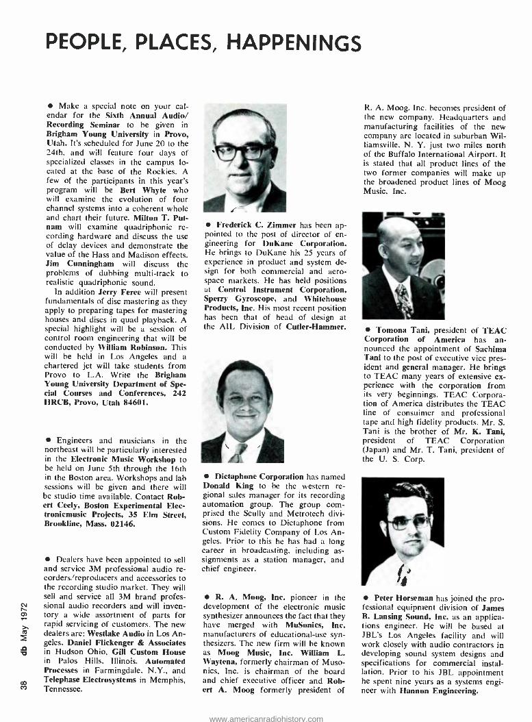
PEOPLE, PLACES, HAPPENINGS
Make a special note on your cal- endar for the Sixth Annual Audio/ Recording Seminar to be given in Brigham Young University in Provo, Utah. It's scheduled for June 20 to the 24th, and will feature four days of specialized classes in the campus lo- cated at the base of the Rockies. A few of the participants in this year's program will be Bert Whyte who will examine the evolution of four channel systems into a coherent whole and chart their future. Milton T. Put- nam will examine quadriphonic re- cording hardware and discuss the use of delay devices and demonstrate the value of the Hass and Madison effects. Jim Cunningham will discuss the problems of dubbing multi -track to realistic quadriphonic sound.
In addition Jerry Feree will present fundamentals of disc mastering as they apply to preparing tapes for mastering houses and discs in quad playback. A special highlight will be a session of control room engineering that will be conducted by William Robinson. This will be held in Los Angeles and a chartered jet will take students from Provo to L.A. Write the Brigham Young University Department of Spe- cial Courses and Conferences, 242 HRCB, Provo, Utah 84601.
Engineers and musicians in the northeast will be particularly interested in the Electronic Music Workshop to be held on June 5th through the 16th in the Boston area. Workshops and lab sessions will be given and there will be studio time available. Contact Rob- ert Ceely, Boston Experimental Elec- tronicmusic Projects, 35 Elm Street, Brookline, Mass. 02146.
Dealers have been appointed to sell and service 3M professional audio re- corders /reproducers and accessories to the recording studio market. They will sell and service all 3M brand profes- sional audio recorders and will inven- tory a wide assortment of parts for rapid servicing of customers. The new dealers are: Westlake Audio in Los An- geles, Daniel Flickenger & Associates in Hudson Ohio, Gill Custom House in Palos Hills. Illinois. Automated Processes in Farmingdale. N.Y., and Telephase Electrosystems in Memphis, Tennessee.
Frederick C. Zimmer has been ap- pointed to the post of director of en- gineering for DuKane Corporation. He brings to DuKane his 25 years of experience in product and system de- sign for both commercial and aero- space markets. He has held positions at Control Instrument Corporation, Sperry Gyroscope, and Whitehouse Products, Inc. His most recent position has been that of head of design at the AIL Division of Cutler- Hammer.
td, Dictaphone Corporation has named
Donald King to be the western re- gional sales manager for its recording automation group. The group com- prised the Scully and Metrotech divi- sions. He comes to Dictaphone from Custom Fidelity Company of Los An- geles. Prior to this he has had a long career in broadcasting, including as- signments as a station manager, and chief engineer.
R. A. Moog, Inc. pioneer in the development of the electronic music synthesizer announces the fact that they have merged with MuSonics, Inc. manufacturers of educational -use syn- thesizers. The new firm will be known as Moog Music, Inc. William L. Waytena, formerly chairman of Muso- nics, Inc. is chairman of the board and chief executive officer and Rob- ert A. Moog formerly president of
R. A. Moog. Inc. becomes president of the new company. Headquarters and manufacturing facilities of the new company are located in suburban Wil- liamsville, N. Y. just two miles north of the Buffalo International Airport. It is stated that all product lines of the two former companies will make up the broadened product lines of Moog Music, Inc.
'Pomona Tani, president of TEAC Corporation of America has an- nounced the appointment of Sachima Tani to the post of executive vice pres- ident and general manager. He brings to TEAC many years of extensive ex- perience with the corporation from its very beginnings. TEAC Corpora- tion of America distributes the TEAC line of consuimer and professional tape and high fidelity products. Mr. S. Tani is the brother of Mr. K. Tani, president of TEAC Corporation (Japan) and Mr. T. Tani, president of the U. S. Corp.
Peter Horseman has joined the pro- fessional equipment division of James B. Lansing Sound, Inc. as an applica- tions engineer. He will he based at JBL's Los Angeles facility and will work closely with audio contractors in developing sound system designs and specifications for commercial instal- lation. Prior to his JBL appointment he spent nine years as a systems engi- neer with Hannon Engineering.
www.americanradiohistory.com
TeleSessions exclusively for :db readers
How many times have you read an unusually stimulating article in db and wished you could trade ideas with others involved in that area? (People who share your problems and speak your language, who are full of surprising insights and new ideas.)
Although group discussions like this happen at conferences, and at chance meetings, our read- ers have been telling us they want it to happen more often and more conveniently. THE ELECTRONIC MEETING Now, without leaving your desk, you can have this kind of valuable, informal discussion. With- out the time and expense of travel, either. Group telephone conferences are held in connection with selected db articles -and we keep each group small. For articles that generate tremen- dous TeleSession' interest, we'll schedule as many separate small group sessions as required.
So readers most interested in each article can dial into an hour -long, freewheeling discussion and build on each other's ideas. TeleSession Company provides the unique telephone con- ference system that repeals geography. Our edi- tors pick the topics and invite authors or guest experts- whenever appropriate. A SURPRISING EXPERIENCE You'll find this specially engineered conference system and the group dynamics different from any "conference call" you may haveexperienced. You dial in over ordinary phone lines from any- where in the country you happen to be at ses- sion time. You're greeted by a session host who introduces everyone and gets things started. Everyone on the line can ask questions, explore ideas (it's amazing how one new idea leads to another), or just listen.
You'll find, even in your first few minutes, that db TeleSessions are more interactive and informal than face -to -face discussions. You always know who's talking, because participants say their first names. You drop formalities and simply chime in whenever you have a comment. Yet there are surprisingly few interruptions.
The result is a stimulating and orderly discus- sion. We've discovered that the participants are willing to reveal the best of their knowledge and ask questions when they don't know something. So what you get is a chain reaction of ideas. One person's knowledge complements everyone else's- though each person forms his own con- clusions. Complete strangers end up talking as though they've known each other for years -and wanting to call on each other's expertise again.
So far, there've been over 700 TeleSessions.
HOW TO RESERVE YOUR TELESESSION "SEAT' Whenever you find a db article especially in- triguing that is marked for TeleSession discus- sion, we hope you will accept our invitation to participate with others who feel the same way. Simply fill out the reservation card and mention the topic for which you wish to reserve a "seat ". We'll promptly reserve a line for you and advise you of your group's scheduled date and time. (If the time we send you conflicts with your schedule you may call 212/725 -2525 and we'll immediately give you an alternate.)
Be sure to mark the scheduled meeting hour we send you in your appointment book; then when your session time arrives simply place a station -to- station call from wherever you are that day to 212/725- 2525.Your session host will greet you and then after a few informal introductions you'll find yourself in one of the most productive meetings you've ever experienced. Wherever you are that day, you can fit the Tele Session hour into whatever you're doing. There's no time lost, no travel or lodging expense.
THE COST We think the fresh viewpoints you share in the first session will prove this to be the most cost - effective form of consulting you ever experi- enced. It's just thirty dollars for each Tele- Session, plus the cost of your simple station -to- station phone call. You may cancel up to five days before the session or have someone else take your "seat." If for any reason your db TeleSession isn't everything we've said it is, merely state the reason for your disappoint- ment on the invoice, return it and owe nothing. A MAGAZINE WITH AN INTERACTIVE FEEDBACK SYSTEM A provocative article. A small interdisciplinary group of professionals like you. A uniquely stim- ulating and convenient meeting environment. You owe it to yourself to give it a try. We look forward to welcoming you. Pick one of the ar- ticles marked for TeleSession and send in the attached card.
i :
i
www.americanradiohistory.com
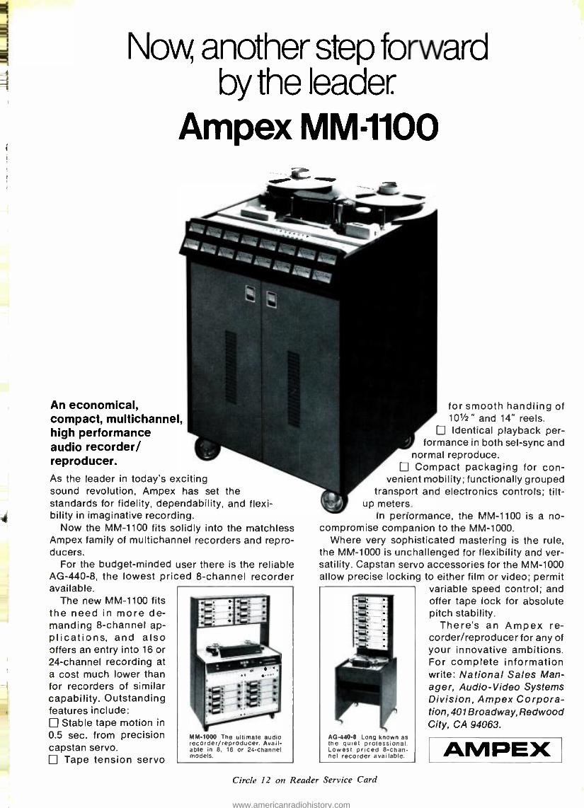
Now another step forward by the leader.
Ampex MM-1100
An economical, compact, multichannel, high performance audio recorder/ reproducer. As the leader in today's exciting sound revolution, Ampex has set the standards for fidelity, dependability, and flexi- bility in imaginative recording.
Now the MM -1100 fits solidly into the matchless Ampex family of multichannel recorders and repro- ducers.
For the budget- minded user there is the reliable AG- 440 -8, the lowest priced 8- channel recorder available.
The new MM -1100 fits the need in more de- manding 8- channel ap- plications, and also offers an entry into 16 or 24- channel recording at a cost much lower than for recorders of similar capability. Outstanding features include:
Stable tape motion in
0.5 sec. from precision capstan servo.
Tape tension servo
MM -1000 The ultimate audio recorder /reproducer. Avail- able in 8. 16 or 24- channel models.
for smooth handling of 101/2" and 14" reels. Identical playback per-
formance in both sel -sync and normal reproduce. Compact packaging for con-
venient mobility; functionally grouped transport and electronics controls; tilt -
up meters. In performance, the MM -1100 is a no-
compromise companion to the MM -1000. Where very sophisticated mastering is the rule,
the MM -1000 is unchallenged for flexibility and ver- satility. Capstan servo accessories for the MM -1000 allow precise locking to either film or video; permit
variable speed control; and offer tape lock for absolute pitch stability.
There's an Ampex re- corder /reproducer for any of your innovative ambitions. For complete information write: National Sales Man- ager, Audio -Video Systems Division, Ampex Corpora- tion, 401 Broadway, Redwood City, CA 94063.
AG -000 -8 Long known as the quiet professional. Lowest priced 8-chan- nel recorder available.
Circle 12 on Reader Service Card
AMPEX
www.americanradiohistory.com


![Revox Center Köln GbR - o o [nap] E · o o [nap] E . Author: peter.serowski@revox-koeln.de Created Date: 5/8/2018 2:02:51 PM](https://img.pdfslide.us/doc/110x75/60cee1fc398f193b1213591b/revox-center-kln-gbr-o-o-nap-e-o-o-nap-e-author-peterserowskirevox-koelnde.jpg)