Embed Size (px)
Citation preview
THE SMALL ANGLE CLEAVAGETECHNIQUE: AN UPDATE
Scott D. WalckMaterials Directorate, Wright Laboratory
WPAFB, OH 45433-6533 USA
John P. McCaffreyInstitute for Microstructural SciencesNational Research Council of CanadaOttawa, Ontario, K1A 0R6 Canada
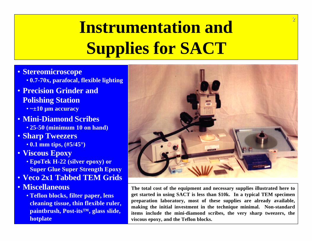
Instrumentation andSupplies for SACT
• Stereomicroscope• 0.7-70x, parafocal, flexible lighting
• Precision Grinder andPolishing Station
• ~±10 µm accuracy
• Mini-Diamond Scribes• 25-50 (minimum 10 on hand)
• Sharp Tweezers• 0.1 mm tips, (#5/45°)
• Viscous Epoxy• EpoTek H-22 (silver epoxy) or
Super Glue Super Strength Epoxy
• Veco 2x1 Tabbed TEM Grids• Miscellaneous
• Teflon blocks, filter paper, lenscleaning tissue, thin flexible ruler,paintbrush, Post-its™, glass slide,hotplate
The total cost of the equipment and necessary supplies illustrated here toget started in using SACT is less than $10k. In a typical TEM specimenpreparation laboratory, most of these supplies are already available,making the initial investment in the technique minimal. Non-standarditems include the mini-diamond scribes, the very sharp tweezers, theviscous epoxy, and the Teflon blocks.
222
There are three objectives of this paper: (i) to present a detailed outline of the steps ofSACT and convey all the new information, tips, and tricks-of-the-trade that we canremember so that others can learn the technique quickly, (ii) to illustrate some of theadvantages of the geometry of SACT samples in the TEM, and (iii) present successfulapplication of SACT to other material systems other than semiconductors that demonstrateits utility.
The Small Angle Cleavage Technique (SACT) is a relatively simple and inexpensive methodof producing superior cross sectional TEM specimens. For speed of preparation, it isunsurpassed. One major limitation is that the the substrate material must cleave orfracture. For this reason, it is readily applied to semiconductor materials. Recently, SACThas been extended to other substrates such as glass, silicon carbide, quartz, sapphire, andother brittle materials. It is particularly well suited for rapidly examining coatings andthin films very soon after they are deposited. Many multilayer films also work, but again,the limitation is adhesion. This paper is an update to the original technique developed andpresented by McCaffrey. Several procedures have been added or modified to simplify thetechnique. For example, a method for mounting the cleaved samples utilizing acommercially available grid is presented. In addition, the advantages that the specialgeometry of the prepared samples have when mounted properly in a double-tilt holder willbe discussed with respect to the angular range of tilting experiments that are now possiblein the TEM.
INTRODUCTION 333
OBJECTIVES
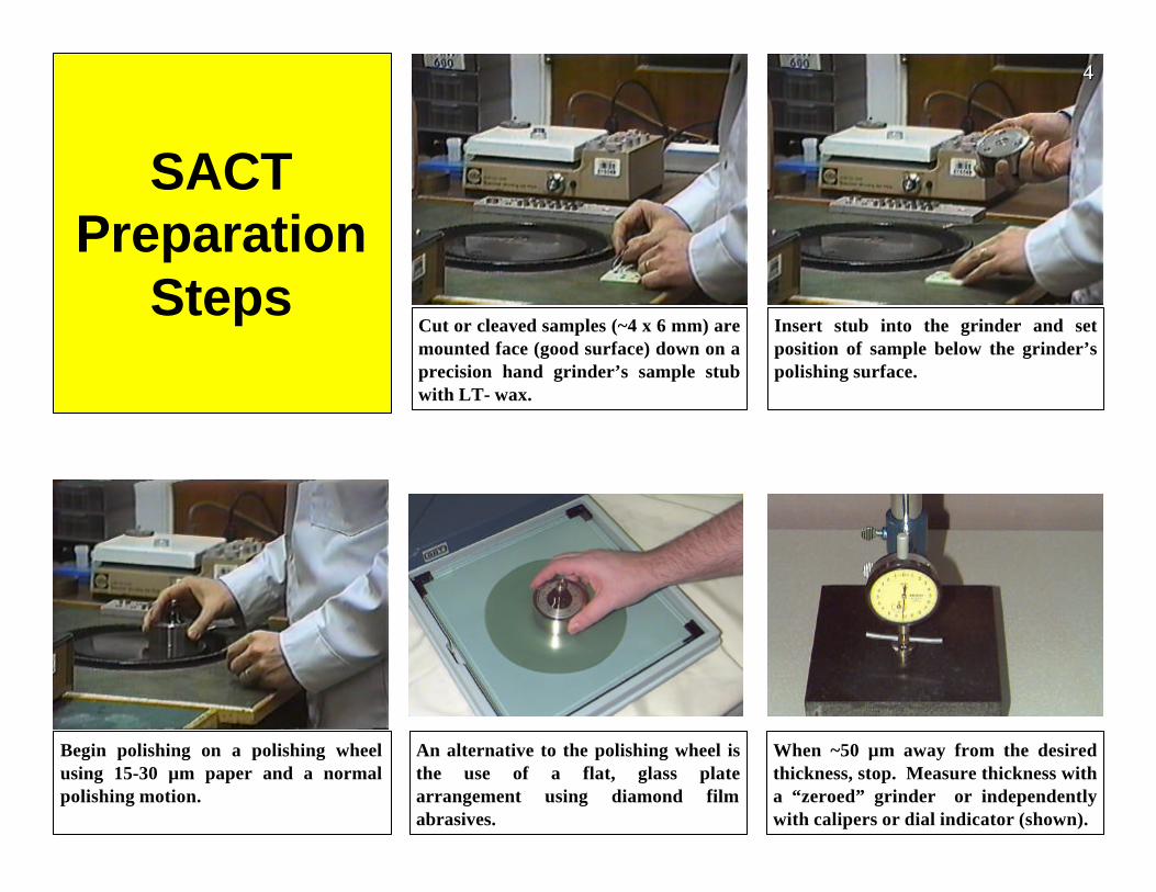
SACTPreparation
StepsCut or cleaved samples (~4 x 6 mm) aremounted face (good surface) down on aprecision hand grinder’s sample stubwith LT- wax.
Insert stub into the grinder and setposition of sample below the grinder’spolishing surface.
Begin polishing on a polishing wheelusing 15-30 µm paper and a normalpolishing motion.
When ~50 µm away from the desiredthickness, stop. Measure thickness witha “zeroed” grinder or independentlywith calipers or dial indicator (shown).
An alternative to the polishing wheel isthe use of a flat, glass platearrangement using diamond filmabrasives.
444
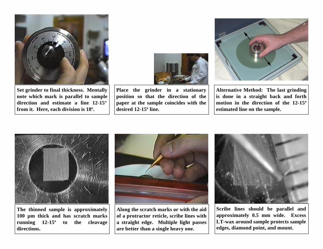
Set grinder to final thickness. Mentallynote which mark is parallel to sampledirection and estimate a line 12-15°from it. Here, each division is 18º.
Alternative Method: The last grindingis done in a straight back and forthmotion in the direction of the 12-15ºestimated line on the sample.
The thinned sample is approximately100 µm thick and has scratch marksrunning 12-15º to the cleavagedirections.
Along the scratch marks or with the aidof a protractor reticle, scribe lines witha straight edge. Multiple light passesare better than a single heavy one.
Scribe lines should be parallel andapproximately 0.5 mm wide. ExcessLT-wax around sample protects sampleedges, diamond point, and mount.
Place the grinder in a stationaryposition so that the direction of thepaper at the sample coincides with thedesired 12-15º line.
555
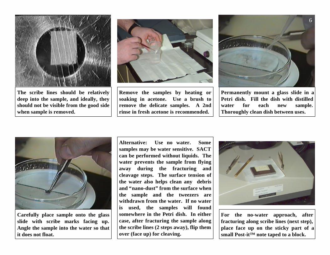
Carefully place sample onto the glassslide with scribe marks facing up.Angle the sample into the water so thatit does not float.
Alternative: Use no water. Somesamples may be water sensitive. SACTcan be performed without liquids. Thewater prevents the sample from flyingaway during the fracturing andcleavage steps. The surface tension ofthe water also helps clean any debrisand “nano-dust” from the surface whenthe sample and the tweezers arewithdrawn from the water. If no wateris used, the samples will foundsomewhere in the Petri dish. In eithercase, after fracturing the sample alongthe scribe lines (2 steps away), flip themover (face up) for cleaving.
The scribe lines should be relativelydeep into the sample, and ideally, theyshould not be visible from the good sidewhen sample is removed.
Remove the samples by heating orsoaking in acetone. Use a brush toremove the delicate samples. A 2ndrinse in fresh acetone is recommended.
Permanently mount a glass slide in aPetri dish. Fill the dish with distilledwater for each new sample.Thoroughly clean dish between uses.
For the no-water approach, afterfracturing along scribe lines (next step),place face up on the sticky part of asmall Post-it™ note taped to a block.
666
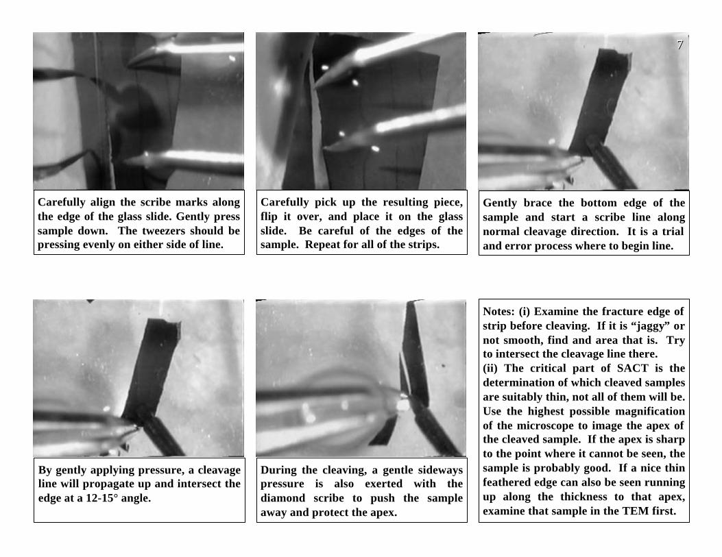
Carefully align the scribe marks alongthe edge of the glass slide. Gently presssample down. The tweezers should bepressing evenly on either side of line.
Carefully pick up the resulting piece,flip it over, and place it on the glassslide. Be careful of the edges of thesample. Repeat for all of the strips.
Gently brace the bottom edge of thesample and start a scribe line alongnormal cleavage direction. It is a trialand error process where to begin line.
By gently applying pressure, a cleavageline will propagate up and intersect theedge at a 12-15° angle.
During the cleaving, a gentle sidewayspressure is also exerted with thediamond scribe to push the sampleaway and protect the apex.
777
Notes: (i) Examine the fracture edge ofstrip before cleaving. If it is “jaggy” ornot smooth, find and area that is. Tryto intersect the cleavage line there.(ii) The critical part of SACT is thedetermination of which cleaved samplesare suitably thin, not all of them will be.Use the highest possible magnificationof the microscope to image the apex ofthe cleaved sample. If the apex is sharpto the point where it cannot be seen, thesample is probably good. If a nice thinfeathered edge can also be seen runningup along the thickness to that apex,examine that sample in the TEM first.
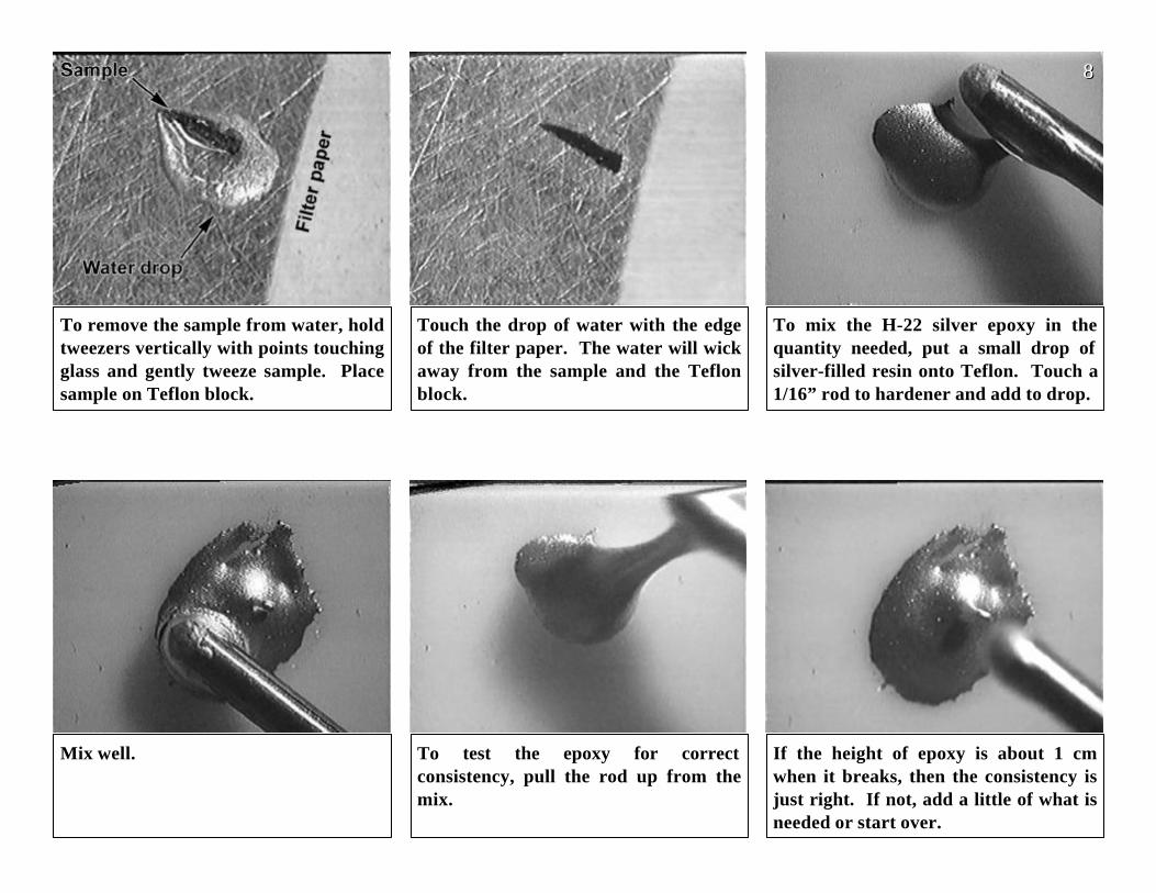
Mix well. To test the epoxy for correctconsistency, pull the rod up from themix.
If the height of epoxy is about 1 cmwhen it breaks, then the consistency isjust right. If not, add a little of what isneeded or start over.
To remove the sample from water, holdtweezers vertically with points touchingglass and gently tweeze sample. Placesample on Teflon block.
Touch the drop of water with the edgeof the filter paper. The water will wickaway from the sample and the Teflonblock.
To mix the H-22 silver epoxy in thequantity needed, put a small drop ofsilver-filled resin onto Teflon. Touch a1/16” rod to hardener and add to drop.
888
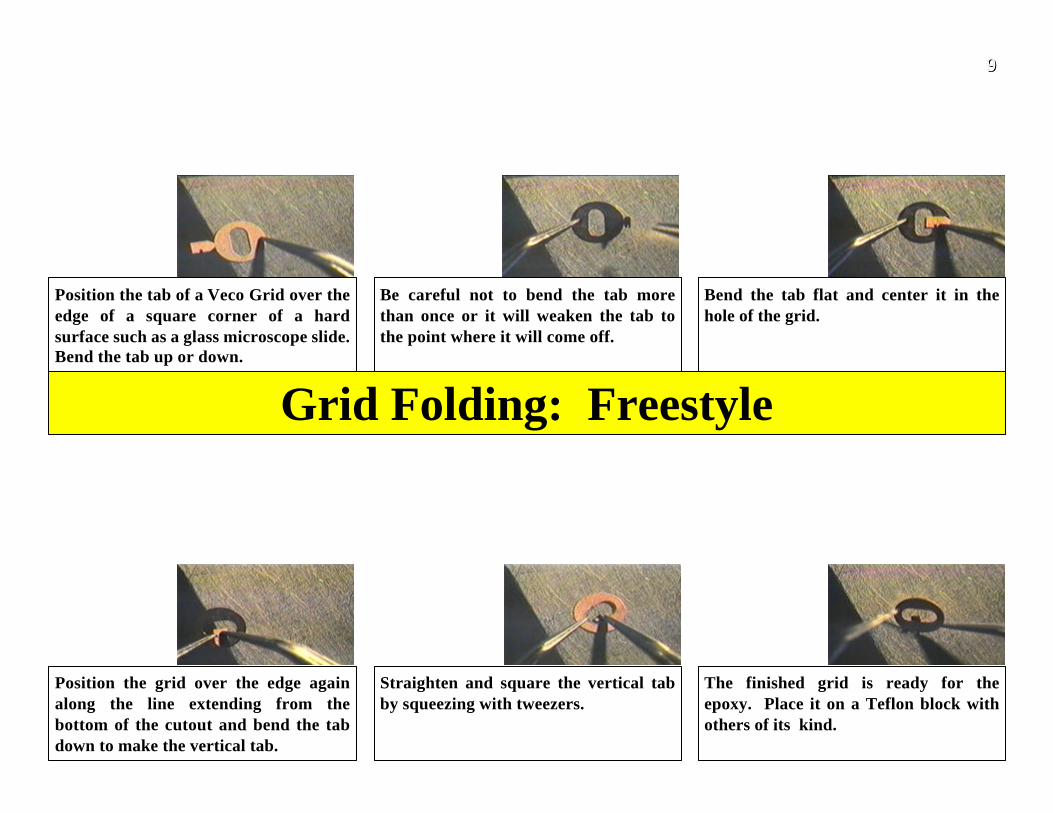
Position the grid over the edge againalong the line extending from thebottom of the cutout and bend the tabdown to make the vertical tab.
Straighten and square the vertical tabby squeezing with tweezers.
The finished grid is ready for theepoxy. Place it on a Teflon block withothers of its kind.
Position the tab of a Veco Grid over theedge of a square corner of a hardsurface such as a glass microscope slide.Bend the tab up or down.
Be careful not to bend the tab morethan once or it will weaken the tab tothe point where it will come off.
Bend the tab flat and center it in thehole of the grid.
999
Grid Folding: Freestyle
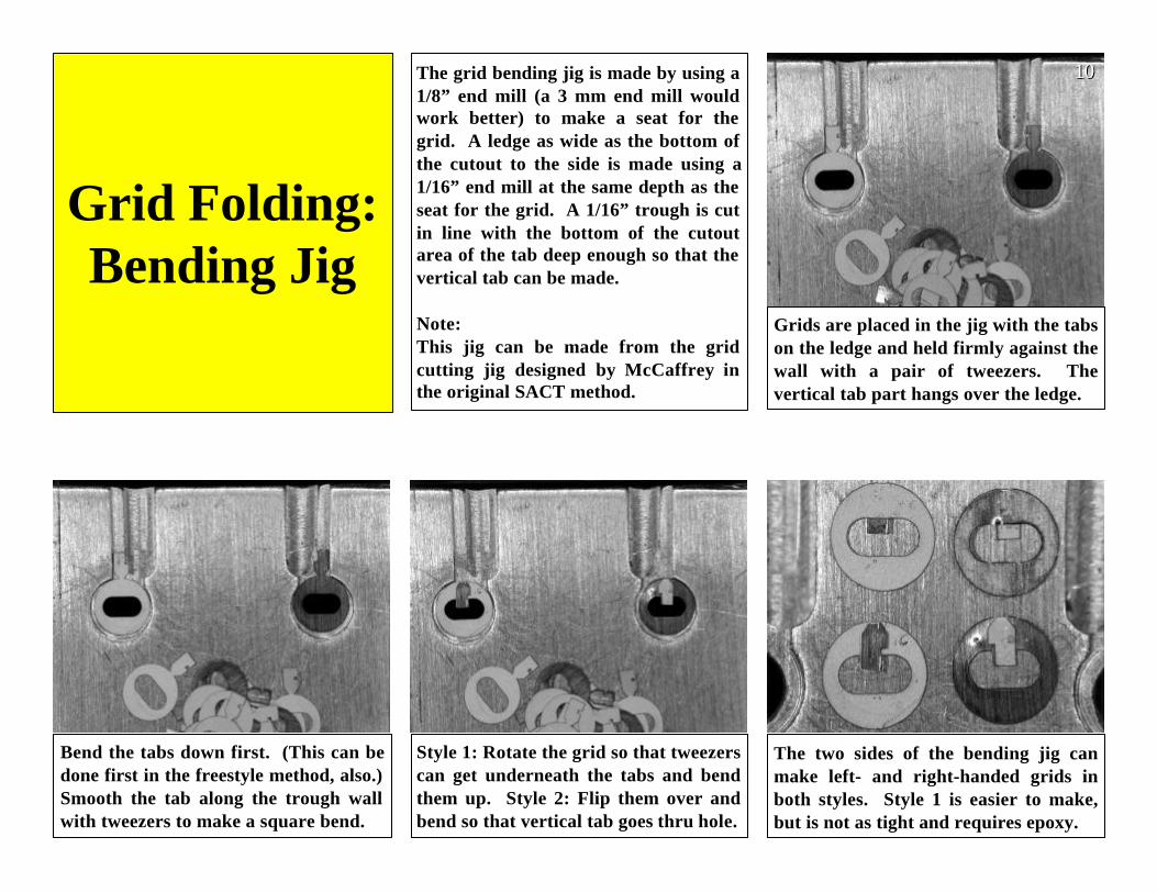
Grids are placed in the jig with the tabson the ledge and held firmly against thewall with a pair of tweezers. Thevertical tab part hangs over the ledge.
Bend the tabs down first. (This can bedone first in the freestyle method, also.)Smooth the tab along the trough wallwith tweezers to make a square bend.
Style 1: Rotate the grid so that tweezerscan get underneath the tabs and bendthem up. Style 2: Flip them over andbend so that vertical tab goes thru hole.
The two sides of the bending jig canmake left- and right-handed grids inboth styles. Style 1 is easier to make,but is not as tight and requires epoxy.
The grid bending jig is made by using a1/8” end mill (a 3 mm end mill wouldwork better) to make a seat for thegrid. A ledge as wide as the bottom ofthe cutout to the side is made using a1/16” end mill at the same depth as theseat for the grid. A 1/16” trough is cutin line with the bottom of the cutoutarea of the tab deep enough so that thevertical tab can be made.
Note:This jig can be made from the gridcutting jig designed by McCaffrey inthe original SACT method.
101010
Grid Folding:Bending Jig
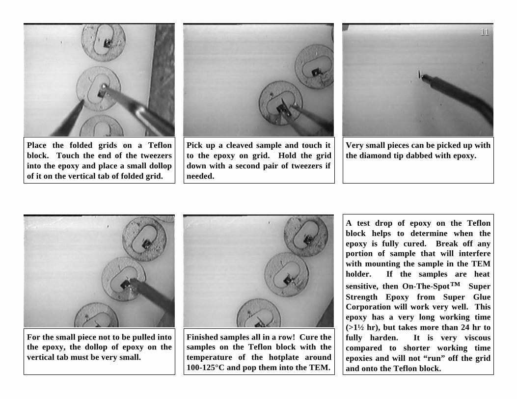
Place the folded grids on a Teflonblock. Touch the end of the tweezersinto the epoxy and place a small dollopof it on the vertical tab of folded grid.
Pick up a cleaved sample and touch itto the epoxy on grid. Hold the griddown with a second pair of tweezers ifneeded.
Very small pieces can be picked up withthe diamond tip dabbed with epoxy.
For the small piece not to be pulled intothe epoxy, the dollop of epoxy on thevertical tab must be very small.
Finished samples all in a row! Cure thesamples on the Teflon block with thetemperature of the hotplate around100-125°C and pop them into the TEM.
A test drop of epoxy on the Teflonblock helps to determine when theepoxy is fully cured. Break off anyportion of sample that will interferewith mounting the sample in the TEMholder. If the samples are heat
sensitive, then On-The-Spot™ SuperStrength Epoxy from Super GlueCorporation will work very well. Thisepoxy has a very long working time(>1½ hr), but takes more than 24 hr tofully harden. It is very viscouscompared to shorter working timeepoxies and will not “run” off the gridand onto the Teflon block.
111111
A
BB
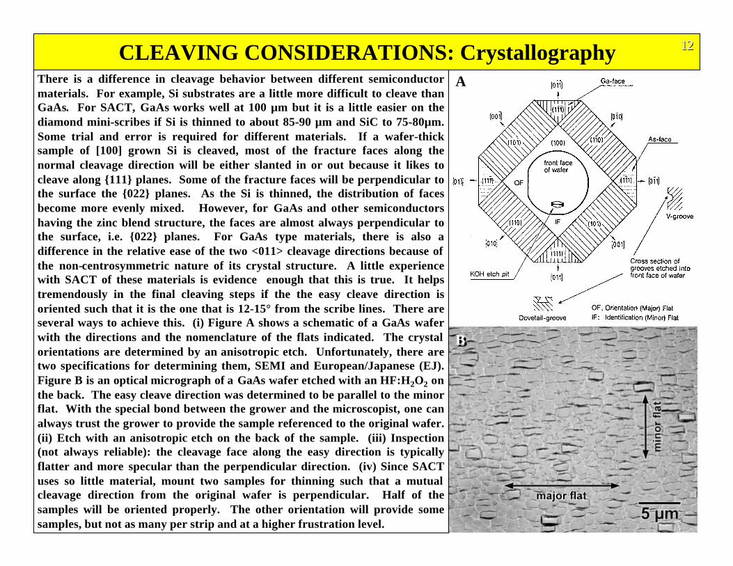
There is a difference in cleavage behavior between different semiconductormaterials. For example, Si substrates are a little more difficult to cleave thanGaAs. For SACT, GaAs works well at 100 µm but it is a little easier on thediamond mini-scribes if Si is thinned to about 85-90 µm and SiC to 75-80µm.Some trial and error is required for different materials. If a wafer-thicksample of [100] grown Si is cleaved, most of the fracture faces along thenormal cleavage direction will be either slanted in or out because it likes tocleave along {111} planes. Some of the fracture faces will be perpendicular tothe surface the {022} planes. As the Si is thinned, the distribution of facesbecome more evenly mixed. However, for GaAs and other semiconductorshaving the zinc blend structure, the faces are almost always perpendicular tothe surface, i.e. {022} planes. For GaAs type materials, there is also adifference in the relative ease of the two <011> cleavage directions because ofthe non-centrosymmetric nature of its crystal structure. A little experiencewith SACT of these materials is evidence enough that this is true. It helpstremendously in the final cleaving steps if the the easy cleave direction isoriented such that it is the one that is 12-15° from the scribe lines. There areseveral ways to achieve this. (i) Figure A shows a schematic of a GaAs waferwith the directions and the nomenclature of the flats indicated. The crystalorientations are determined by an anisotropic etch. Unfortunately, there aretwo specifications for determining them, SEMI and European/Japanese (EJ).Figure B is an optical micrograph of a GaAs wafer etched with an HF:H2O2 onthe back. The easy cleave direction was determined to be parallel to the minorflat. With the special bond between the grower and the microscopist, one canalways trust the grower to provide the sample referenced to the original wafer.(ii) Etch with an anisotropic etch on the back of the sample. (iii) Inspection(not always reliable): the cleavage face along the easy direction is typicallyflatter and more specular than the perpendicular direction. (iv) Since SACTuses so little material, mount two samples for thinning such that a mutualcleavage direction from the original wafer is perpendicular. Half of thesamples will be oriented properly. The other orientation will provide somesamples, but not as many per strip and at a higher frustration level.
CLEAVING CONSIDERATIONS: Crystallography 121212
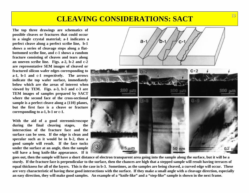
The top three drawings are schematics ofpossible cleaves or fractures that could occurin a single crystal material; a-1 indicates aperfect cleave along a perfect scribe line, b-1shows a series of cleavage steps along a flat-bottomed scribe line, and c-1 shows a randomfracture consisting of cleaves and tears alongan uneven scribe line. Figs. a-2, b-2 and c-2are representative SEM images of cleaved orfractured silicon wafer edges corresponding toa-1, b-1 and c-1 respectively. The arrowsindicate the top wafer surface, immediatelybelow which are the areas of interest whenviewed by TEM. Figs. a-3, b-3 and c-3 areTEM images of samples prepared by SACTwhere the second face of the cross-sectionalsample is a perfect cleave along a {110} planes,but the first face is a cleave or fracturecorresponding to a-1, b-1 or c-1.
With the aid of a good stereomicroscopeduring the final cleaving stages, theintersection of the fracture face and thesurface can be seen. If the edge is clean andspecular such as it would be in b-2, then agood sample will result. If the face tucksunder the surface at an angle, then the samplewill have a long knife-like appearance. If itgoes out, then the sample will have a short distance of electron transparent area going into the sample along the surface, but it will be asturdy. If the fracture face is perpendicular to the surface, then the chances are high that a stepped sample will result having terraces ofequal thickness for all of the layers. This is the case in b-3. Sometimes, as the samples are being cleaved, a curved edge will occur. Theseare very characteristic of having these good intersections with the surface. If they make a small angle with a cleavage direction, especiallyan easy direction, they will make good samples. An example of a “knife-like” and a “step-like” sample is shown in the next frame.
CLEAVING CONSIDERATIONS: SACT 131313
CLEAVING CONSIDERATIONS: Sample Geometry
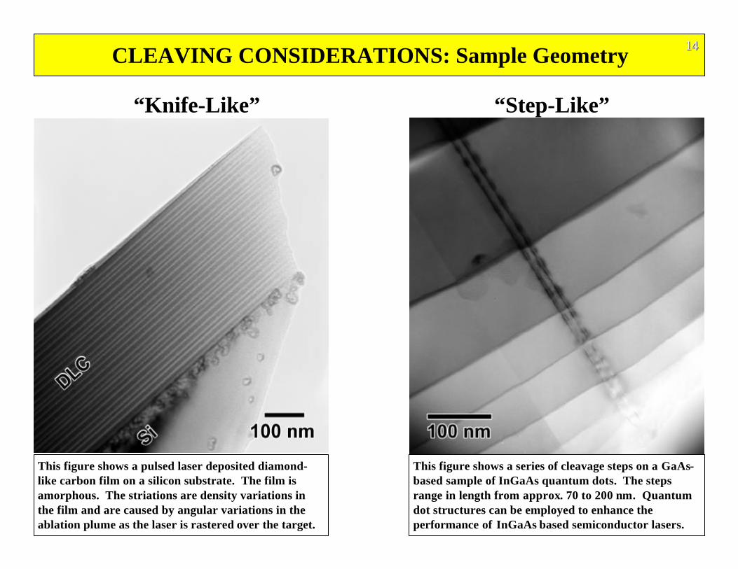
This figure shows a series of cleavage steps on a GaAs-based sample of InGaAs quantum dots. The stepsrange in length from approx. 70 to 200 nm. Quantumdot structures can be employed to enhance theperformance of InGaAs based semiconductor lasers.
This figure shows a pulsed laser deposited diamond-like carbon film on a silicon substrate. The film isamorphous. The striations are density variations inthe film and are caused by angular variations in theablation plume as the laser is rastered over the target.
141414
“Knife-Like” “Step-Like”
Quickly Examine Many Samples: If the samples are mounted into the TEM stage in the same orientation with their apex along the centerof the specimen rod, as shown in the two figures, then finding the transparent area and making it eucentric in the stage can be done veryquickly. This also enables many samples to be quickly examined. First pull/pull the sample out/in along the rod axis so that the beam is inthe grid hole and the front ledge of the tab is seen. Go left or right until either the sample or the side edge of the tab is reached. (Of course,go the other way if the side edge of the tab is reached.) Pull the sample back until the tip is seen. This is either the back or surface of thesample. If it is rough, it is the back side and go to the other side of the sample. If the sample’s surface is not parallel to the beam, then theshadow image of the surface will have steps visible, much like viewing a staircase from above and to the side. Rotate the rod axis (“x”-tilt)until the surface is straight and the steps are not visible. (This is similar to viewing the stairs from the top of the staircase.) If a previoussample was imaged at the eucentric height, focused, and the astigmatism corrected, then adjust the height until minimum contrast is seenin the image with the objective aperture out. If the sample is mounted fairly parallel along the rod’s axis, i.e. not tilted in the “y”-axis, thenthe sample can be judged worth of further TEM investigation. If not, take it out and put another sample in. The turn-around timerequired for screening samples for quality is about 5-10 min which includes mounting the sample in the TEM stage.
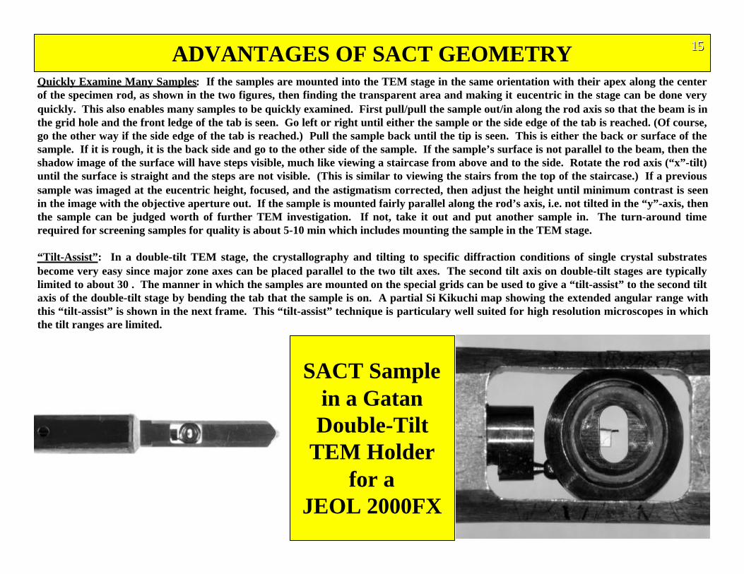
“Tilt-Assist”: In a double-tilt TEM stage, the crystallography and tilting to specific diffraction conditions of single crystal substratesbecome very easy since major zone axes can be placed parallel to the two tilt axes. The second tilt axis on double-tilt stages are typicallylimited to about 30 . The manner in which the samples are mounted on the special grids can be used to give a “tilt-assist” to the second tiltaxis of the double-tilt stage by bending the tab that the sample is on. A partial Si Kikuchi map showing the extended angular range withthis “tilt-assist” is shown in the next frame. This “tilt-assist” technique is particulary well suited for high resolution microscopes in whichthe tilt ranges are limited.
ADVANTAGES OF SACT GEOMETRY 151515
SACT Samplein a GatanDouble-Tilt
TEM Holderfor a
JEOL 2000FX
161616
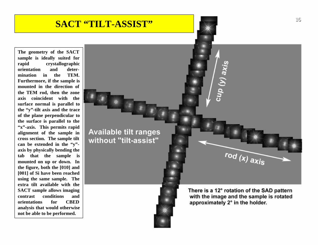
The geometry of the SACTsample is ideally suited forrapid crystallographicorientation and deter-mination in the TEM.Furthermore, if the sample ismounted in the direction ofthe TEM rod, then the zoneaxis coincident with thesurface normal is parallel tothe “y”-tilt axis and the traceof the plane perpendicular tothe surface is parallel to the“x”-axis. This permits rapidalignment of the sample incross section. The sample tiltcan be extended in the “y”-axis by physically bending thetab that the sample ismounted on up or down. Inthe figure, both the [010] and[001] of Si have been reachedusing the same sample. Theextra tilt available with theSACT sample allows imagingcontrast conditions andorientations for CBEDanalysis that would otherwisenot be able to be performed.
SACT “TILT-ASSIST”
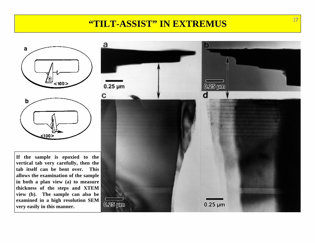
“TILT-ASSIST” IN EXTREMUS 171717
If the sample is epoxied to thevertical tab very carefully, then thetab itself can be bent over. Thisallows the examination of the samplein both a plan view (a) to measurethickness of the steps and XTEMview (b). The sample can also beexamined in a high resolution SEMvery easily in this manner.
PLAN VIEW TEM SAMPLES FROM SACT
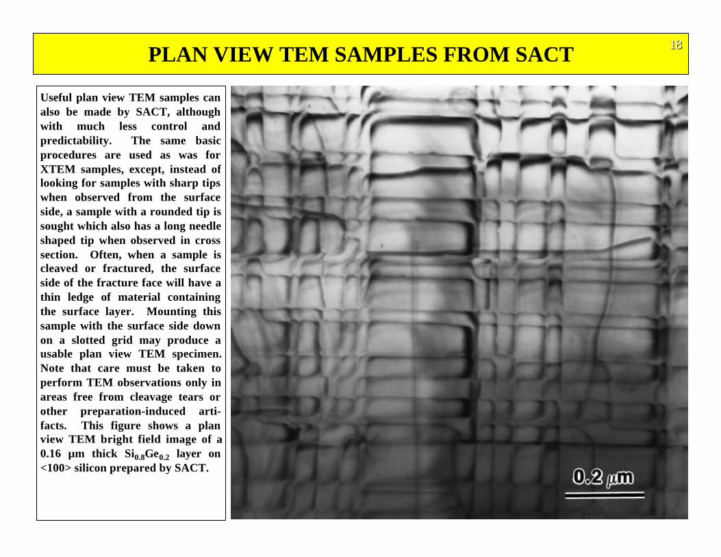
Useful plan view TEM samples canalso be made by SACT, althoughwith much less control andpredictability. The same basicprocedures are used as was forXTEM samples, except, instead oflooking for samples with sharp tipswhen observed from the surfaceside, a sample with a rounded tip issought which also has a long needleshaped tip when observed in crosssection. Often, when a sample iscleaved or fractured, the surfaceside of the fracture face will have athin ledge of material containingthe surface layer. Mounting thissample with the surface side downon a slotted grid may produce ausable plan view TEM specimen.Note that care must be taken toperform TEM observations only inareas free from cleavage tears orother preparation-induced arti-facts. This figure shows a planview TEM bright field image of a0.16 µm thick Si0.8Ge0.2 layer on<100> silicon prepared by SACT.
181818
JOHN AND SCOTT’S SACT TIPS AND TRICKS•Cleaving Technique:
•It helps to have a clean, sharp diamond scribe for this step. Clean debris off of the tip of the scribe using a Post-itnote.
•For easily cleaved material such as the III-V materials, scribe lightly starting near the apex and draw the scribeback while gently adding pressure. A little pressure to the outside will pull the cleaved part away from strip.
•For silicon, try a light scribe line, as straight as possible, and then lay the scribe along the line near the bottom ofthe sample and press the scribe gently down (slight rolling motion might help). This works particularly well usingthe Post-it note instead of water.
•Use a Post-It Note for Final Cleaving:•The Post-it note works very well as a substitute for the water. It has a resilience to it that helps the cleave linespropagate straight to the edge. Very little of the glue, if any, will stick to the sample and it can be cleaned in acetoneafter the epoxy cures. Very little damage can be done to the thin area due to excessive handling as in the case offishing the samples out of the water, putting them down on the Teflon with a drop of water, wicking the water awaywith filter paper, and picking them up for final mounting. With the Post-it, the sample can be mounted directlyafter it is cleaved or saved in a corner of the Post-it with others. With modest care, only the bottom ground portionof the sample touches the Post-it. Originally, it was thought that there would be excessive debris on the surface inthe electron transparent area, but this proved not to be the case. In addition, it is very easy to shorten the cleavedsamples to the appropriate length for mounting while they are on the Post-it so that the excess overhang doesn’thave to be broken off of the final sample after the epoxy is cured, further minimizing handling.
•Coat a Sample with Carbon:•A small price to pay for SACT samples in terms of imaging is that there are no amorphous areas in the sample ifthe material does not start out that way and astigmatism correction can be difficult. One trick is to put a light coatof carbon on the sample surface prior to beginning the process. This puts a little amorphous material in the regionof interest that can be used to correct for astigmatism.
191919
JOHN AND SCOTT’S SACT TIPS AND TRICKS•Fracturing Brittle Substrates:
•Glass and other brittle materials can be made with SACT. The substrate should be as thin as possible because it ishard on the diamond tips. Saving broken diamond scribes for fracturing the brittle substrates is well advised.When performing the final cleave (fracture), the tip of the scribe should be as close to the edge as possible. Almostas much sideways pressure is applied as downward pressure. Patience is important here. Allow the tip of the scribeto start a crack propagating and control the speed with the pressure. Look for curved surfaces that have good cleanedges and try to intersect the surface with the propagating crack.
•Quick Examination of Films:•Often, only the microstructure of the thin film or coating is of interest, not the substrate or the substrate/filminterface. If this is the case, consider growing these types of films on No. 0 glass cover slips. They have a thicknessof 80-130 µm and can be prepared directly without any pre-thinning. The No. 1 glass cover slips are 130-170 µmthick and are hard on the diamond scribes, but samples can be prepared from them. Unlike single crystalsubstrates with known orientations, the amorphous glass substrates are more difficult to align properly in the TEMfor minimum thickness and having the surface parallel to the beam. It is recommended that amorphous substratesamples be put into the TEM perpendicular to the rods axis. It is harder to find the minimum thickness of thesample and this orients the sample with the tilt axis that maintains the eucentric condition. To set up the surface ofthe sample parallel with the beam, observe the thicker part of the film/substrate interface and tilt with the “y”-axisto obtain the best image of the interface.
202020
EXAMPLES OF SACT PREPARED SAMPLES 212121
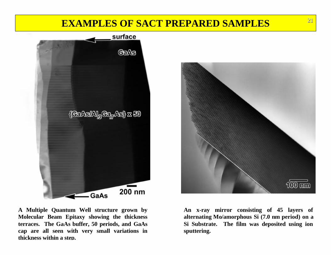
A Multiple Quantum Well structure grown byMolecular Beam Epitaxy showing the thicknessterraces. The GaAs buffer, 50 periods, and GaAscap are all seen with very small variations inthickness within a step.
An x-ray mirror consisting of 45 layers ofalternating Mo/amorphous Si (7.0 nm period) on aSi Substrate. The film was deposited using ionsputtering.
EXAMPLES OF SACT PREPARED SAMPLES 222222
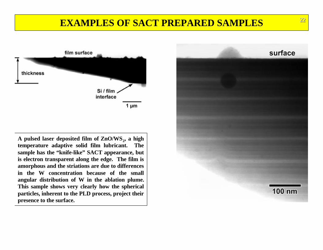
A pulsed laser deposited film of ZnO/WS2, a hightemperature adaptive solid film lubricant. Thesample has the “knife-like” SACT appearance, butis electron transparent along the edge. The film isamorphous and the striations are due to differencesin the W concentration because of the smallangular distribution of W in the ablation plume.This sample shows very clearly how the sphericalparticles, inherent to the PLD process, project theirpresence to the surface.
WORLD’S SMALLEST RULER 232323
REFERENCES 242424
1. J. P. McCaffrey, Ultramicroscopy, 38, (1991) 149.
2. J. P. McCaffrey, Specimen Preparation for Transmission Electron Microscopy III, eds. Ron Anderson, Bryan Tracy, andJohn Bravman, Materials Research Society, Pittsburgh, Materials Research Society Symposium Proceedings., Vol 254,1992 p. 109.
3. John P. McCaffrey, Microscopy Research and Technique, 24, (1993) 180.
4. Scott D. Walck, A Simplified Method for Modifying TEM Copper Grids For Use with the Small Angle Cleavage Technique,Microscopy Today, (96-4), (1996).
5. S. D. Walck and J. P. McCaffrey, The Small Angle Cleavage Technique Applied to Coatings and Thin Films, submitted toThin Solid Films, March, 1997.
SOURCES FOR SUPPLIES
1. Precision Hand Grinder:
South Bay Technology, Inc., San Clemente, CA (www.southbaytech.com)
2. Stackable Lapping Tray or Polishing Station, Diamond Lapping Film:
South Bay Technology, Inc., San Clemente, CA (www.southbaytech.com)
3. Epoxy: EpoTek H-22, Epoxy Tchnology, Inc, Billerica , MA
or On-the-Spot™ Super Strength Epoxy, Super Glue Corporation, (Wal-Mart)
4. Mini Diamond Scribes, Tweezers, Tabbed Grids, 100 count grid boxes, paint brush, Plastic Scale:
South Bay Technology, Inc., San Clemente, CA (www.southbaytech.com)