Embed Size (px)
Citation preview
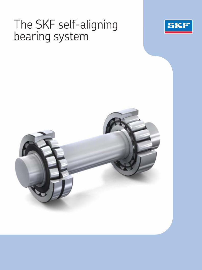
The SKF self-aligning bearing system
The SKF brand now stands for more than ever before, and means more to you as a valued customer.
While SKF maintains its leadership as the hallmark of quality bearings throughout the world, new dimensions in technical advances, product support and services have evolved SKF into a truly solutions-oriented supplier, creating greater value for customers.
These solutions encompass ways to bring greater productivity to customers, not only with breakthrough application-specific products, but also through leading-edge design simulation tools and consultancy services, plant asset efficiency maintenance programmes, and the industry’s most advanced supply management techniques.
The SKF brand still stands for the very best in rolling bearings, but it now stands for much more.
SKF – the knowledge engineering company
3 Summary
4 The conventional self-aligning bearing system
4 Bearings in rotating equipment4 The conventional self-aligning bearing
system5 Cause of bearing failure6 Influence of friction6 Unstable load distribution7 A typical example of shaft expansion
and its effects8 Axial force over time – characteristic
examples
9 The SKF self-aligning bearing system10 CARB toroidal roller bearing10 Low load performance12 Improving operating conditions and
reliability14 Reducing costs by downsizing14 Light loads, high speeds15 Eliminating the risk of poor operating
conditions15 The compromise-free solution16 Improvements with the SKF self-aligning
bearing system18 Influences of the SKF self-aligning
bearing system for different types of machines
20 SKF – the knowledge engineering company
Contents
2
Summary
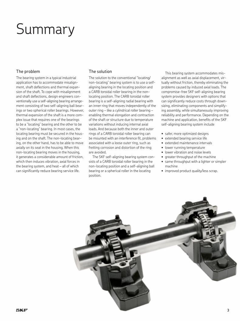
The problem The bearing system in a typical industrial application has to accommodate misalign-ment, shaft deflections and thermal expan-sion of the shaft. To cope with misalignment and shaft deflections, design engineers con-ventionally use a self-aligning bearing arrange-ment consisting of two self-aligning ball bear-ings or two spherical roller bearings. However, thermal expansion of the shaft is a more com-plex issue that requires one of the bearings to be a “locating” bearing and the other to be a “non-locating” bearing. In most cases, the locating bearing must be secured in the hous-ing and on the shaft. The non-locating bear-ing, on the other hand, has to be able to move axially on its seat in the housing. When this non-locating bearing moves in the housing, it generates a considerable amount of friction, which then induces vibration, axial forces in the bearing system, and heat – all of which can significantly reduce bearing service life.
The solutionThe solution to the conventional “locating/non-locating” bearing system is to use a self-aligning bearing in the locating position and a CARB toroidal roller bearing in the non- locating pos ition. The CARB toroidal roller bearing is a self-aligning radial bearing with an inner ring that moves independently of the outer ring – like a cylindrical roller bearing – enabling thermal elong ation and contraction of the shaft or structure due to temperature variations without inducing internal axial loads. And because both the inner and outer rings of a CARB toroidal roller bearing can be mounted with an interference fit, problems associated with a loose outer ring, such as fretting corrosion and distortion of the ring are avoided.
The SKF self-aligning bearing system con-sists of a CARB toroidal roller bearing in the non-locating position and a self-aligning ball bearing or a spherical roller in the locating position.
This bearing system accommodates mis-alignment as well as axial displacement, vir-tually without friction, thereby eliminating the problems caused by induced axial loads. The compromise-free SKF self-aligning bearing system provides designers with options that can significantly reduce costs through down-sizing, eliminating components and simplify-ing assembly, while simultaneously improving reliability and performance. Depending on the machine and application, benefits of the SKF self-aligning bearing system include
• safer,moreoptimizeddesigns• extendedbearingservicelife• extendedmaintenanceintervals• lowerrunningtemperature• lowervibrationandnoiselevels• greaterthroughputofthemachine• samethroughputwithalighterorsimpler
machine• improvedproductquality/lessscrap.
3
The conventional self-aligning bearing system
Bearings in rotating equipmentIn typical industrial equipment, rotating shafts are generally supported by two anti-friction (rolling) bearings, one at each end of the shaft. In addition to supporting radial loads, one of the bearings must locate the shaft relative to its housing and support any axial loads imposed on the shaft. This bearing is referred to as the “locating” bearing.
The other bearing, referred to as the “non-locating” bearing, must also support radial loads, but should also be able to move axially to accommodate any of the following conditions
• thermalelongationandcontractionoftheshaft or structure due to temperature variations
• manufacturingtolerancesofthestructure• tolerance stack-up.
This second bearing is referred to as the “non-locating”, “floating” or “free” bearing.
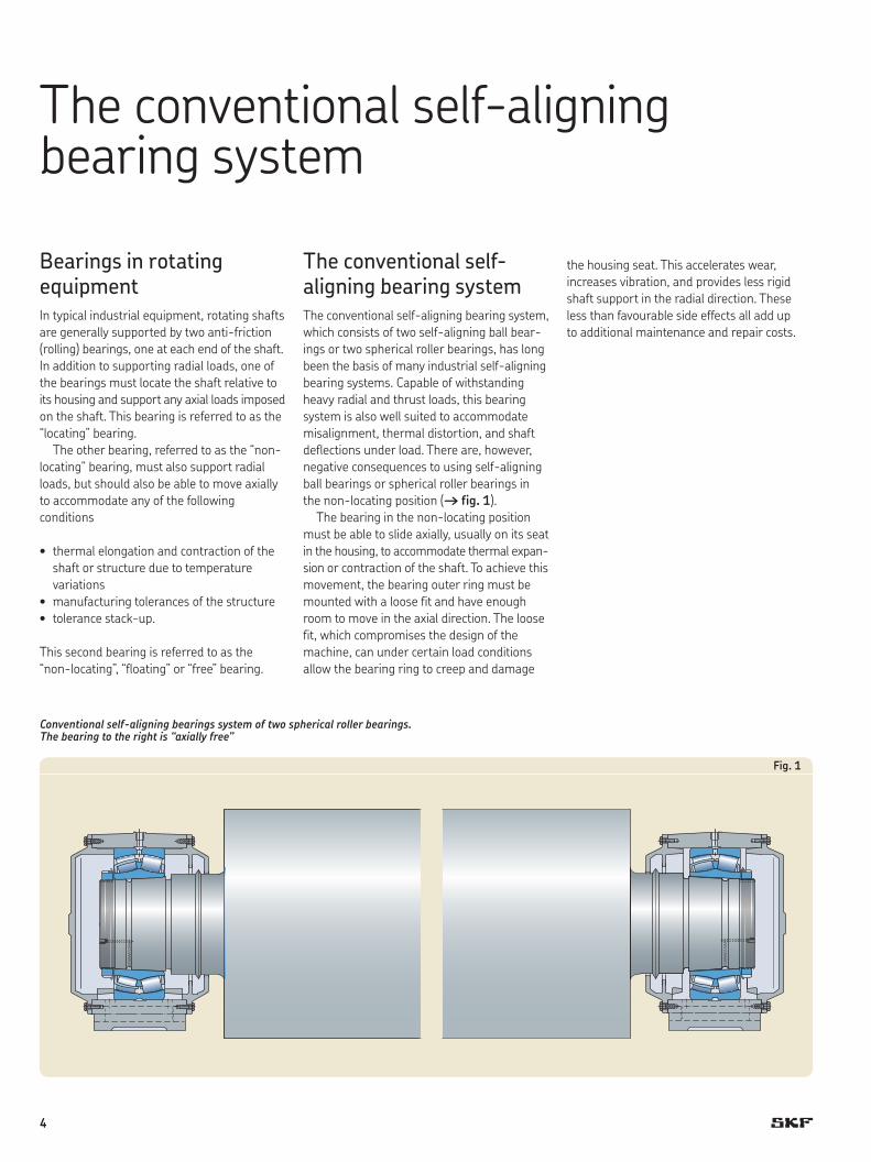
The conventional self-aligning bearing systemThe conventional self-aligning bearing system, which consists of two self-aligning ball bear-ings or two spherical roller bearings, has long been the basis of many industrial self-aligning bearing systems. Capable of withstanding heavy radial and thrust loads, this bearing system is also well suited to accommodate misalignment, thermal distortion, and shaft deflections under load. There are, however, negative consequences to using self-aligning ball bearings or spherical roller bearings in the non-locating position († fig. 1).
The bearing in the non-locating position must be able to slide axially, usually on its seat in the housing, to accommodate thermal expan-sion or contraction of the shaft. To achieve this movement, the bearing outer ring must be mounted with a loose fit and have enough room to move in the axial direction. The loose fit, which compromises the design of the machine, can under certain load conditions allow the bearing ring to creep and damage
the housing seat. This accelerates wear, increases vibration, and provides less rigid shaft support in the radial direction. These less than favourable side effects all add up to additional maintenance and repair costs.
Conventional self-aligning bearings system of two spherical roller bearings. The bearing to the right is “axially free”
Fig. 1
4
Cause of bearing failure
Because the non-locating bearing needs a loose fit on its seat to accommodate axial expansion and contraction of the shaft, the loose fit must be maintained during opera-tion. Maintaining this loose fit is not as simple as it might seem and can be restricted for any of the following reasons:
• Duringstart-up,asmachinecomponentsare warming up, the outer ring of a bearing usually expands faster than the housing bore. This difference in the rate of expan-sion can eliminate the loose fit between the bearing and its seat to restrict axial movement.
• Iftheformofthebearingseatinthehous-ing is not within specification, the bearing ring will be held in place and will be unable to move axially. This can be due to an oval or tapered seat, or, more commonly, a dis-torted seat that results when the base sup-port is not sufficiently flat or rigid.
• Underunfavourableloadconditions,aloosering can create a condition known as fret-ting corrosion, which can effectively “rust” the bearing ring in place.
• Wearofthebearingseatcanalsolocatethe bearing.
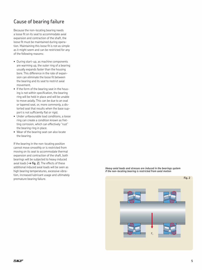
If the bearing in the non-locating position cannot move smoothly or is restricted from moving on its seat to accommodate thermal expansion and contraction of the shaft, both bearings will be subjected to heavy induced axial loads († fig. 2). The effects of these additional induced axial loads will be seen as high bearing temperatures, excessive vibra-tion, increased lubricant usage and ultimately premature bearing failure.
Heavy axial loads and stresses are induced in the bearings system if the non-locating bearing is restricted from axial motion
Fr
Fig. 2
5
Influence of friction
A more general, but less recognized, conse-quence of a bearing installed with a loose fit is that there is always a certain amount of friction between the loose bearing ring and its seat in the housing (or on the shaft). In a conventional bearing system, the shaft must overcome this frictional resistance before the bearing will move on its seat.
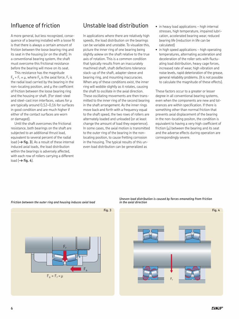
This resistance has the magnitude Fa = Fr ¥ m, where Fa is the axial force, Fr is the radial load carried by the bearing in the non-locating position, and m the coefficient of friction between the loose bearing ring and the housing or shaft. (For steel-steel and steel-cast iron interfaces, values for m are typically around 0,12–0,16 for surfaces in good condition and are much higher if either of the contact surfaces are worn or damaged).
Until the shaft overcomes the frictional resistance, both bearings on the shaft are subjected to an additional thrust load, equivalent to several percent of the radial load († fig. 3). As a result of these internal induced axial loads, the load distribution within the bearings is adversely affected, with each row of rollers carrying a different load († fig. 4).
Unstable load distribution
In applications where there are relatively high speeds, the load distribution on the bearings can be variable and unstable. To visualize this, picture the inner ring of one bearing being slightly askew on the shaft relative to the true axis of rotation. This is a common condition that typically results from an inaccurately machined shaft, shaft deflections tolerance stack-up of the shaft, adapter sleeve and bearing ring, and mounting inaccuracies. When any of these conditions exist, the inner ring will wobble slightly as it rotates, causing the shaft to oscillate in the axial direction. These oscillating movements are then trans-mitted to the inner ring of the second bearing in the shaft arrangement. As the inner rings move back and forth with a frequency equal to the shaft speed, the two rows of rollers are alternately loaded and unloaded (or at least change the amount of load they experience). In some cases, the axial motion is transmitted to the outer ring of the bearing in the non- locating position, to cause fretting corrosion in the housing. The typical results of this un -even load distribution can be generalized as
• inheavyloadapplications–highinternalstresses, high temperature, impaired lubri-cation, accelerated bearing wear, reduced bearing life (reduction in life can be calculated)
• inhighspeedapplications–highoperatingtemperatures, alternating acceleration and deceleration of the roller sets with fluctu-ating load distribution, heavy cage forces, increased rate of wear, high vibration and noise levels, rapid deterioration of the grease, general reliability problems. (It is not possible to calculate the magnitude of these effects).
These factors occur to a greater or lesser degree in all conventional bearing systems, even when the components are new and tol-erances are within specification. If there is something other than normal friction that prevents axial displacement of the bearing in the non-locating positon, the condition is equivalent to having a very high coefficient of friction (m) between the bearing and its seat and the adverse effects during operation are corres pondingly severe.
Fr
Fa
Friction between the outer ring and housing induces axial load
Fig. 3
Fr
Uneven load distribution is caused by forces emanating from friction in the axial direction
Fig. 4
Fa = Fr × µ
6
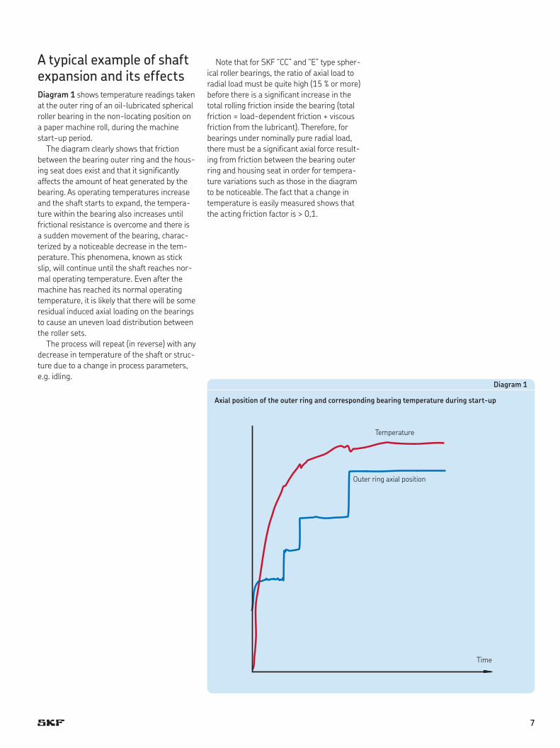
A typical example of shaft expansion and its effectsDiagram 1 shows temperature readings taken at the outer ring of an oil-lubric ated spherical roller bearing in the non-locating position on a paper machine roll, during the machine start -up period.
The diagram clearly shows that friction between the bearing outer ring and the hous-ing seat does exist and that it significantly affects the amount of heat generated by the bearing. As operating temperatures increase and the shaft starts to expand, the tempera-ture within the bearing also increases until frictional resistance is overcome and there is a sudden movement of the bearing, charac-terized by a noticeable decrease in the tem-perature. This phenomena, known as stick slip, will continue until the shaft reaches nor-mal operating temperature. Even after the machine has reached its normal operating temperature, it is likely that there will be some residual induced axial loading on the bearings to cause an uneven load distribution between the roller sets.
The process will repeat (in reverse) with any decrease in temperature of the shaft or struc-ture due to a change in process parameters, e.g. idling.
Note that for SKF “CC” and “E” type spher -ical roller bearings, the ratio of axial load to radial load must be quite high (15 % or more) before there is a significant increase in the total rolling friction inside the bearing (total friction = load-dependent friction + viscous friction from the lubricant). Therefore, for bearings under nominally pure ra dial load, there must be a significant axial force result-ing from friction between the bearing outer ring and housing seat in order for tempera-ture variations such as those in the diagram to be noticeable. The fact that a change in temperature is easily measured shows that the acting friction factor is > 0,1.
Diagram 1
Axial position of the outer ring and corresponding bearing temperature during start-up
Time
Temperature
Outer ring axial position
7
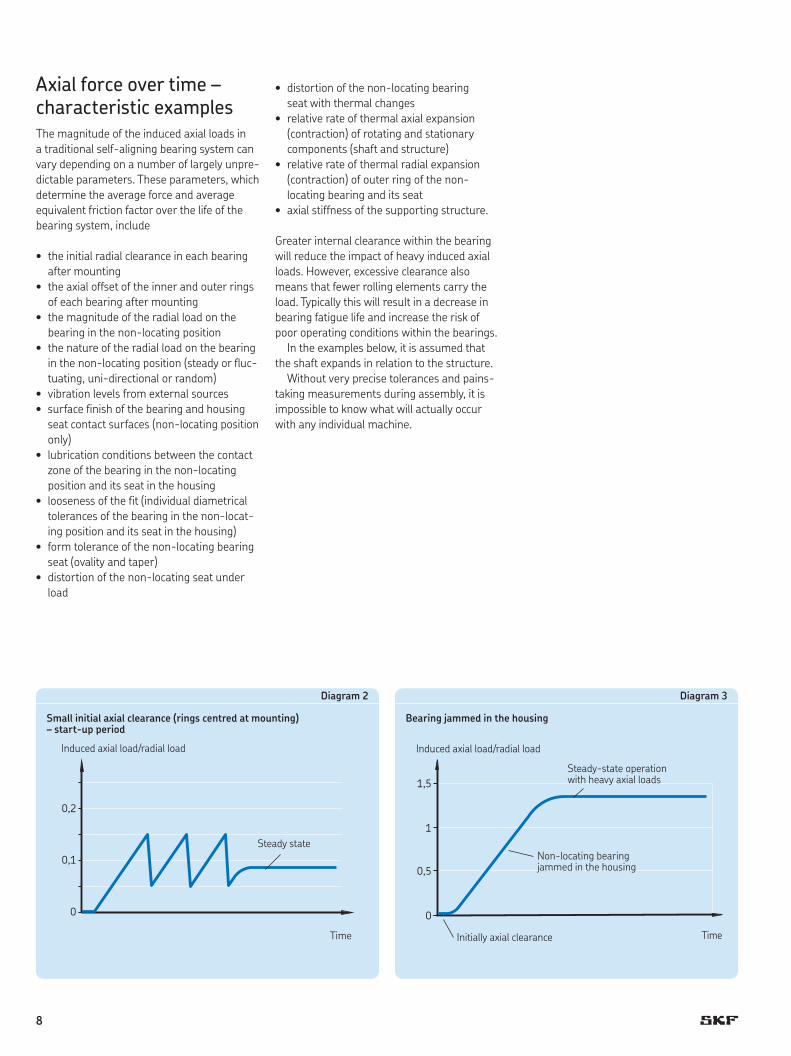
Axial force over time – characteristic examplesThe magnitude of the induced axial loads in a traditional self-aligning bearing system can vary depending on a number of largely unpre-dictable parameters. These parameters, which determine the average force and average equivalent friction factor over the life of the bearing system, include
• theinitialradialclearanceineachbearingafter mounting
• theaxialoffsetoftheinnerandouterringsof each bearing after mounting
• themagnitudeoftheradialloadonthebearing in the non-locating position
• thenatureoftheradialloadonthebearingin the non-locating position (steady or fluc-tuating, uni-directional or random)
• vibrationlevelsfromexternalsources• surfacefinishofthebearingandhousing
seat contact surfaces (non-locating position only)
• lubricationconditionsbetweenthecontactzone of the bearing in the non-locating position and its seat in the housing
• loosenessofthefit(individualdiametricaltolerances of the bearing in the non-locat-ing position and its seat in the housing)
• formtoleranceofthenon-locatingbearingseat (ovality and taper)
• distortionofthenon-locatingseatunderload
• distortionofthenon-locatingbearing seat with thermal changes
• relativerateofthermalaxialexpansion(contraction) of rotating and stationary components (shaft and structure)
• relativerateofthermalradialexpansion(contraction) of outer ring of the non- locating bearing and its seat
• axialstiffnessofthesupportingstructure.
Greater internal clearance within the bearing will reduce the impact of heavy induced axial loads. However, excessive clearance also means that fewer rolling elements carry the load. Typically this will result in a decrease in bearing fatigue life and increase the risk of poor operating conditions within the bearings.
In the examples below, it is assumed that the shaft expands in relation to the structure.
Without very precise tolerances and pains-taking measurements during assembly, it is impossible to know what will actually occur with any individual machine.
0,2
0,1
0
Steady state
Induced axial load/radial load
Diagram 2
Small initial axial clearance (rings centred at mounting) – start-up period
1,5
0,5
1
0
Initially axial clearance
Induced axial load/radial load
Diagram 3
Bearing jammed in the housing
Non-locating bearing jammed in the housing
Steady-state operation with heavy axial loads
Time Time
8
The SKF self-aligning bearing system
Not so long ago, compromise was a part of every bearing system that had to accommo-date axial expansion of the shaft. The CARB toroidal roller bearing developed by SKF changed that. Today, with a CARB toroidal roller bearing in the non-locating bearing position and a self-aligning ball bearing or a spherical roller bearing in the locating pos-ition, machine designers can optimize their application and provide more value to their customers with improved reliability and increased service life.
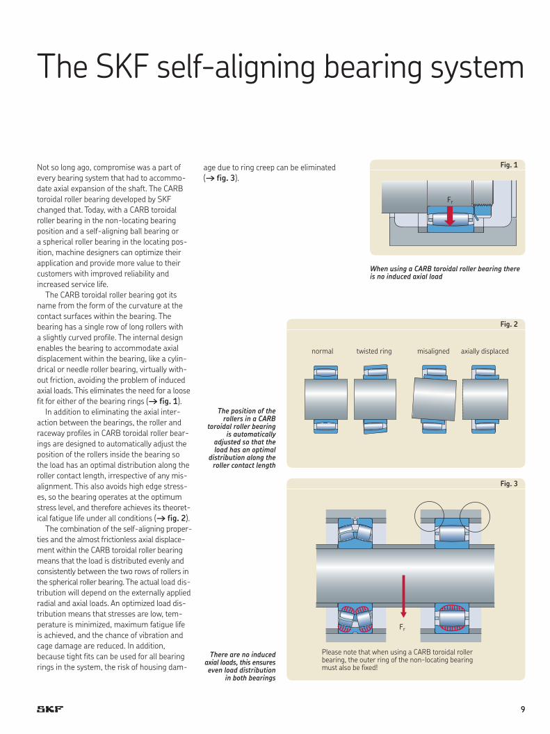
The CARB toroidal roller bearing got its name from the form of the curvature at the contact surfaces within the bearing. The bearing has a single row of long rollers with a slightly curved profile. The internal design enables the bearing to accommodate axial displacement within the bearing, like a cylin-drical or needle roller bearing, virtually with-out friction, avoiding the problem of induced axial loads. This eliminates the need for a loose fit for either of the bearing rings († fig. 1).
In addition to eliminating the axial inter- action between the bearings, the roller and raceway profiles in CARB toroidal roller bear-ings are designed to automatically adjust the position of the rollers inside the bearing so the load has an optimal distribution along the roller contact length, irrespective of any mis-alignment. This also avoids high edge stress-es, so the bearing operates at the optimum stress level, and therefore achieves its theoret-ical fatigue life under all conditions († fig. 2).
The combination of the self-aligning proper-ties and the almost frictionless axial displace-ment within the CARB toroidal roller bearing means that the load is distributed evenly and consistently between the two rows of rollers in the spherical roller bearing. The actual load dis-tribution will depend on the externally applied radial and axial loads. An optimized load dis-tribution means that stresses are low, tem-perature is minimized, maximum fatigue life is achieved, and the chance of vibration and cage damage are reduced. In addition, because tight fits can be used for all bearing rings in the system, the risk of housing dam-
age due to ring creep can be eliminated († fig. 3).
There are no induced axial loads, this ensures even load distribution
in both bearings
The position of the rollers in a CARB
toroidal roller bearing is automatically
adjusted so that the load has an optimal
distribution along the roller contact length
When using a CARB toroidal roller bearing there is no induced axial load
Fr
Fig. 1
Fig. 3
Please note that when using a CARB toroidal roller bearing, the outer ring of the non-locating bearing must also be fixed!
Fr
Fig. 2
normal twisted ring misaligned axially displaced
9
CARB toroidal roller bearing
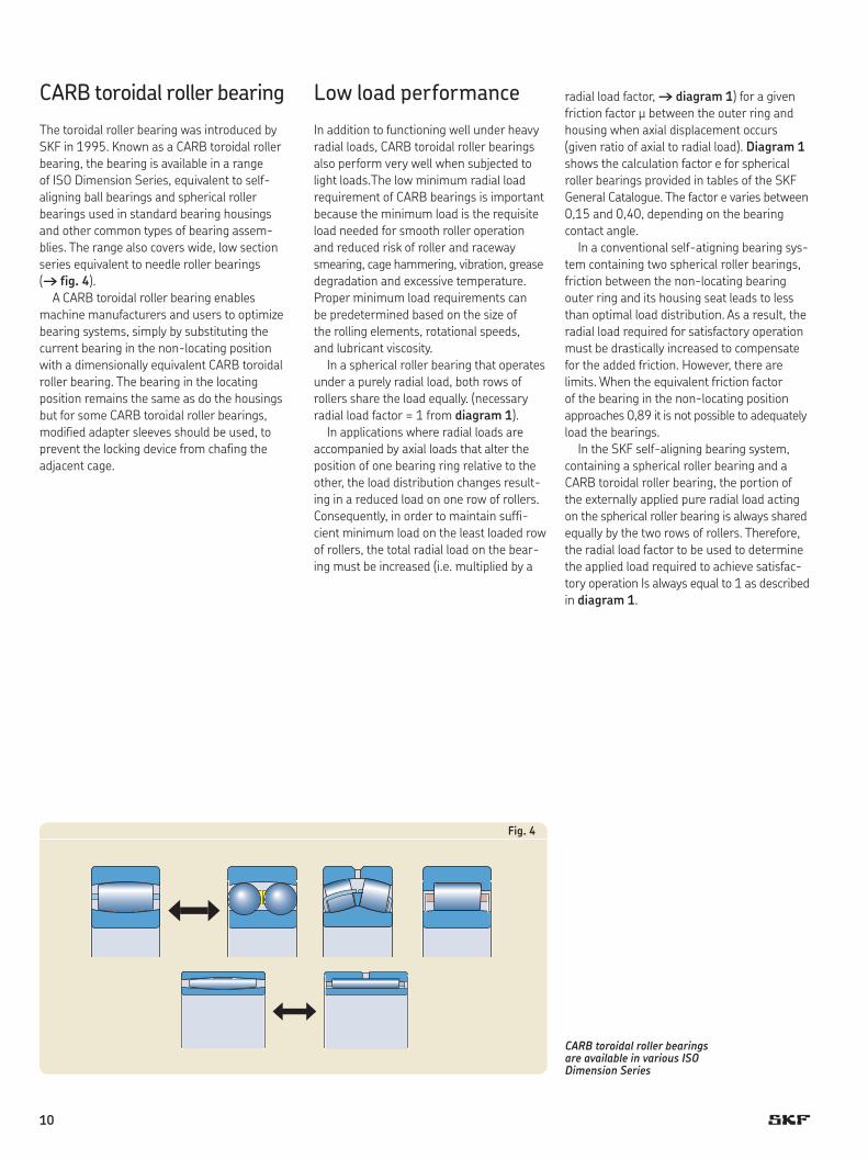
The toroidal roller bearing was introduced by SKF in 1995. Known as a CARB toroidal roller bearing, the bearing is available in a range of ISO Dimension Series, equivalent to self-aligning ball bearings and spherical roller bearings used in stand ard bearing housings and other common types of bearing assem-blies. The range also covers wide, low section series equivalent to needle roller bearings († fig. 4).
A CARB toroidal roller bearing enables machine manufacturers and users to optimize bearing systems, simply by substituting the current bearing in the non-locating position with a dimensionally equivalent CARB toroidal roller bearing. The bearing in the locating position remains the same as do the housings but for some CARB toroidal roller bearings, modified adapter sleeves should be used, to prevent the locking device from chafing the adjacent cage.
Low load performance
In addition to functioning well under heavy radial loads, CARB toroidal roller bearings also perform very well when subjected to light loads.The low minimum radial load requirement of CARB bearings is important because the minimum load is the requisite load needed for smooth roller operation and reduced risk of roller and raceway smearing, cage hammering, vibration, grease degradation and excessive temperature. Proper minimum load requirements can be predetermined based on the size of the rolling elements, rotational speeds, and lubricant viscosity.
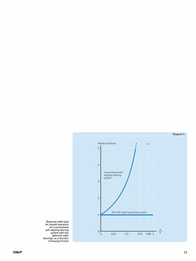
In a spherical roller bearing that operates under a purely radial load, both rows of rollers share the load equally. (necessary radial load factor = 1 from diagram 1).
In applications where radial loads are accompanied by axial loads that alter the position of one bearing ring relative to the other, the load distribution changes result-ing in a reduced load on one row of rollers. Consequently, in order to maintain suffi-cient minimum load on the least loaded row of rollers, the total radial load on the bear-ing must be increased (i.e. multiplied by a
radial load factor, † diagram 1) for a given friction factor µ between the outer ring and housing when axial displacement occurs ( given ratio of axial to radial load). Diagram 1 shows the calculation factor e for spherical roller bearings provided in tables of the SKF General Catalogue. The factor e varies between 0,15 and 0,40, depending on the bearing contact angle.
In a conventional self-atigning bearing sys-tem containing two spherical roller bearings, friction between the non-locating bearing outer ring and its housing seat leads to less than optimal load distribution. As a result, the radial load required for satisfactory operation must be drastically increased to compensate for the added friction. However, there are limits. When the equivalent friction factor of the bearing in the non-locating position approaches 0,89 it is not possible to adequately load the bearings.
In the SKF self-aligning bearing system, containing a spherical roller bearing and a CARB toroidal roller bearing, the portion of the externally applied pure radial load acting on the spherical roller bearing is always shared equally by the two rows of rollers. Therefore, the radial load factor to be used to determine the applied load required to achieve satisfac-tory operation Is always equal to 1 as described in diagram 1.
CARB toroidal roller bearings are available in various ISO Dimension Series
Fig. 4
10
5
4
3
2
1
0m
∞
0 0,25 0,5 0,75 0,89 1 e
Conventional self-aligning bearing system
Diagram 1
SKF self-aligning bearing system
Radial load factor
Required radial load for smooth operation
of a conventional self-aligning bearing
system with two spherical roller
bearings, as a function of housing friction
11
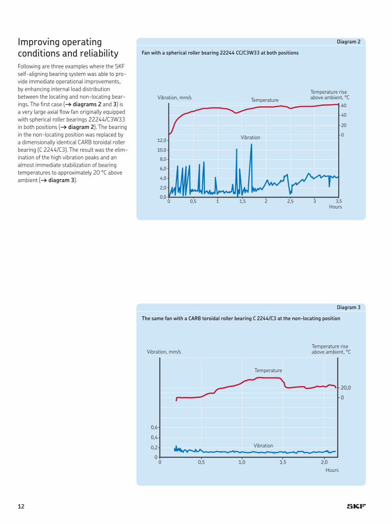
Improving operating conditions and reliabilityFollowing are three examples where the SKF self-aligning bearing system was able to pro-vide immediate operational improvements, by enhancing internal load distribution between the locating and non-locating bear-ings. The first case († diagrams 2 and 3) is a very large axial flow fan originally equipped with spherical roller bearings 22244/C3W33 in both positions († diagram 2). The bearing in the non-locating position was replaced by a dimensionally identical CARB toroidal roller bearing (C 2244/C3). The result was the elim-ination of the high vibration peaks and an almost immediate stabilization of bearing temperatures to approximately 20 °C above ambient († diagram 3).
12,0
10,0
8,0
6,0
4,0
2,0
0,00 0,5 1 1,5 2 2,5 3 3,5
0
20
40
60
Hours
Vibration
Vibration, mm/s
Diagram 2
Fan with a spherical roller bearing 22244 CC/C3W33 at both positions
20,0
0
0,6
0,4
0,2
00 0,5 1,0 1,5 2,0
Hours
Temperature
Vibration, mm/s
Diagram 3
The same fan with a CARB toroidal roller bearing C 2244/C3 at the non-locating position
TemperatureTemperature rise above ambient, °C
Temperature rise above ambient, °C
Vibration
12
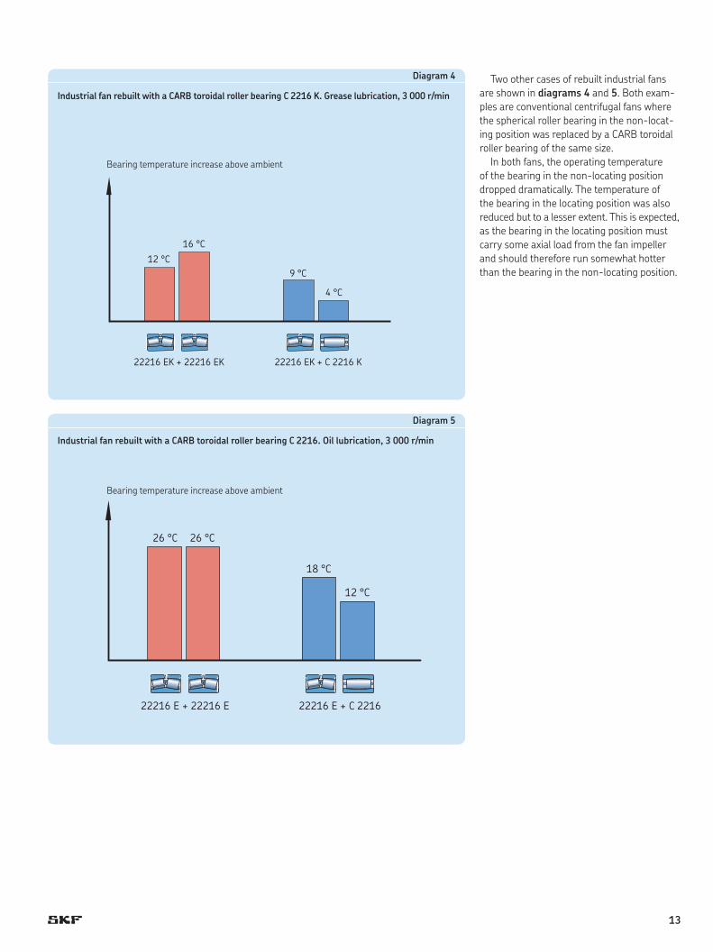
Two other cases of rebuilt industrial fans are shown in diagrams 4 and 5. Both exam-ples are conventional centrifugal fans where the spherical roller bearing in the non-locat-ing position was replaced by a CARB toroidal roller bearing of the same size.
In both fans, the operating temperature of the bearing in the non-locating position dropped dramatically. The temperature of the bearing in the locating position was also reduced but to a lesser extent. This is expected, as the bearing in the locating position must carry some axial load from the fan impeller and should therefore run somewhat hotter than the bearing in the non-locating position.
12 °C
22216 EK + 22216 EK 22216 EK + C 2216 K
16 °C
9 °C
4 °C
Bearing temperature increase above ambient
Diagram 4
Industrial fan rebuilt with a CARB toroidal roller bearing C 2216 K. Grease lubrication, 3 000 r/min
22216 E + 22216 E 22216 E + C 2216
26 °C
18 °C
12 °C
26 °C
Bearing temperature increase above ambient
Diagram 5
Industrial fan rebuilt with a CARB toroidal roller bearing C 2216. Oil lubrication, 3 000 r/min
13
Reducing costs by downsizingPerformance enhancements and productivity improvements are not the only benefits that can be realized by using the SKF self-aligning bearing system. When a CARB toroidal roller bearing is in the non-locating position, the induced axial load, Fa, equals zero for both bearings. In a conventional self-aligning bear-ing system, induced axial loads within both bearings must be calculated using the formu-la (Fa = Fr ¥ m). Once these forces are realized, it is a simple matter to calculate the difference in fatigue life obtained in each bearing system. In applications where the life of a conventional self-aligning bearing system restricts perform-ance, substituting the non-locating bearing with a CARB toroidal roller bearing can sig-nificantly extend service life.
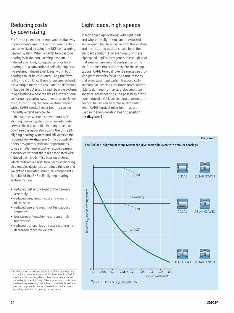
In instances where a conventional self-aligning bearing system provides adequate service life, it is possible, in many cases, to downsize the application using the SKF self-aligning bearing system and still achieve the required life († diagram 6). This possibility offers designers significant opportunities to use smaller, more cost-effective bearing assemblies without the risks associated with induced axial loads. This bearing system, which features a CARB toroidal roller bearing, also enables designers to reduce the size and weight of associated structural components. Benefits of the SKF self-aligning bearing system include
• reducedcostandweightofthebearingassembly
• reducedsize,length,costandweight of the shaft
• reducedsizeandweightofthesupportstructure1)
• lessstringentmachiningandassemblytolerances1)
• reducedtransportationcostsresultingfromdecreased machine weight.
Light loads, high speeds
In high speed applications, with light loads and where misalignment can be expected, self-aligning ball bearings in both the locating and non-locating positions have been the standard solution. However, many of these high speed applications generate enough heat that axial expansion and contraction of the shaft can be a major concern. For these appli-cations, CARB toroidal roller bearings can pro-vide great benefits for all the same reasons that were described earlier. Because self-aligning ball bearings are much more suscep-tible to damage from axial preloading than spherical roller bearings, the possibility of fric-tion-induced axial loads leading to premature bearing failure can be virtually eliminated when CARB toroidal roller bearings are used in the non-locating bearing position († diagram 7).
1,20
0,70
0,37
00
0,05 0,1 0,15*) 0,2 0,25 0,3 0,35 0,4
1
23148 CC/W33 23148 CC/W33
C 3148 23148 CC/W33
C 3144 23144 CC/W33
Diagram 6
The SKF self-aligning bearing system can give better life even with smaller bearings
*) µ = 0,15 for steel against cast iron
Friction coefficient µ
Rela
tive
L 10
life
for b
earin
g sy
stem
1) As there is no risk of cross-location of the bearings due to the frictionless internal axial displacement in a CARB toroidal roller bearing, there is less importance placed upon the form and rigidity of the supporting structure for the bearings, meaning that lighter, more flexible and less precise components can be tolerated without a corre-sponding reduction in bearing performance
downsizing
14
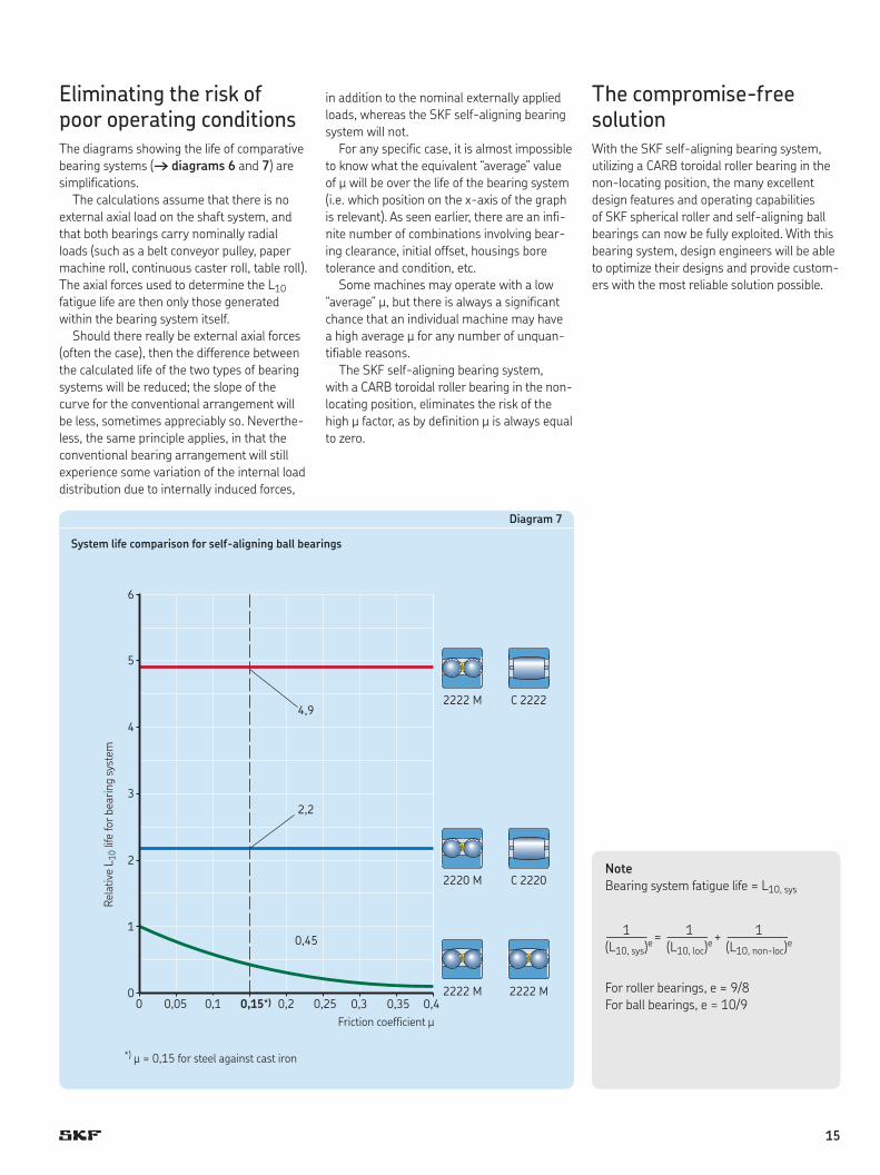
Eliminating the risk of poor operating conditionsThe diagrams showing the life of comparative bearing systems († diagrams 6 and 7) are simplifications.
The calculations assume that there is no external axial load on the shaft system, and that both bearings carry nominally radial loads (such as a belt conveyor pulley, paper machine roll, continuous caster roll, table roll). The axial forces used to determine the L10 fatigue life are then only those generated within the bearing system itself.
Should there really be external axial forces (often the case), then the difference between the calculated life of the two types of bearing systems will be reduced; the slope of the curve for the conventional arrangement will be less, sometimes appreciably so. Neverthe-less, the same principle applies, in that the conventional bearing arrangement will still experience some variation of the internal load distribution due to internally induced forces,
in addition to the nominal externally applied loads, whereas the SKF self-aligning bearing system will not.
For any specific case, it is almost impossible to know what the equivalent “average” value of m will be over the life of the bearing system (i.e. which position on the x-axis of the graph is relevant). As seen earlier, there are an infi-nite number of combinations involving bear-ing clearance, initial offset, housings bore tolerance and condition, etc.
Some machines may operate with a low “average” m, but there is always a significant chance that an individual machine may have a high average m for any number of unquan-tifiable reasons.
The SKF self-aligning bearing system, with a CARB toroidal roller bearing in the non- locating position, eliminates the risk of the high m factor, as by definition m is always equal to zero.
The compromise-free solutionWith the SKF self-aligning bearing system, utilizing a CARB toroidal roller bearing in the non-locating position, the many excellent design features and operating capabilities of SKF spherical roller and self-aligning ball bearings can now be fully exploited. With this bearing system, design engineers will be able to optimize their designs and provide custom-ers with the most reliable solution possible.
00
1
2
3
4
5
6
0,05 0,1 0,15*) 0,2 0,25 0,3 0,35 0,4
C 22222222 M
C 22202220 M
2222 M 2222 M
4,9
2,2
0,45
Diagram 7
System life comparison for self-aligning ball bearings
Rela
tive
L 10
life
for b
earin
g sy
stem
Friction coefficient µ
NoteBearing system fatigue life = L10, sys
1 1 1 ——— = ——— + –———— (L10, sys)e (L10, loc)e (L10, non-loc)e
For roller bearings, e = 9/8For ball bearings, e = 10/9
*) µ = 0,15 for steel against cast iron
15
Tight fit possible
Even and con-sistent load distribution
No housing wear
No vibration
Reduced maintenance costs
No axial vibration
Low cage forces
Less risk of underloading
Reduced cage failure
Longer grease life
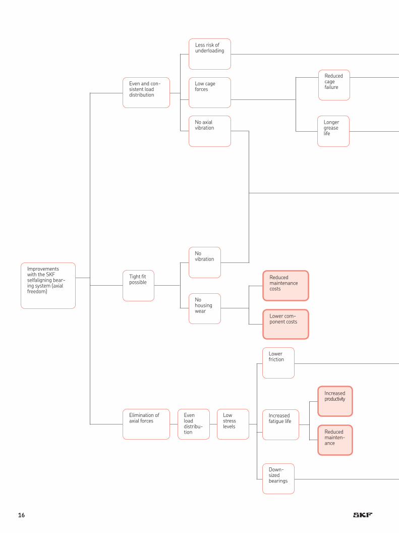
Improvements with the SKF self aligning bear-ing system (axial freedom)
Elimination of axial forces
Even load distribu- tion
Lower friction
Low stress levels
Increased fatigue life
Down-sized bearings
Reduced mainten- ance
Increased product ivity
Lower com-ponent costs
16
Lower grease cost
Reduced temp era - ture
Improved product quality
Lower grease cost
Reduced mainten- ance
Increased product- ivity Reduced
vibration
Low noise
Increased grease life
Less risk of smearing
Improved bearing reliability
Increased lubricant film thickness
Increased productivity
Lower reject costs
Reduced maintenance
Increased productivity
General machine improvement
Lower price
No risk of under- loading
Reduced mainten- ance
Less risk of cage failure
Increased grease life
Reduced wear
Increased product - ivity
Lower power usage
Reduced tempera- ture
Low friction
Increased lubricant film thickness
Lower grease cost
Reduced mainten- ance
Lower power usage
Reduced vibration
Lower noise
Longer grease life
Less risk of smearing
General machine improve- ment
Increased product quality
Reduced mainten- ance
Increased product - ivity
Lower reject costs
Lower grease cost
Improved bearing reliability
Longer grease life
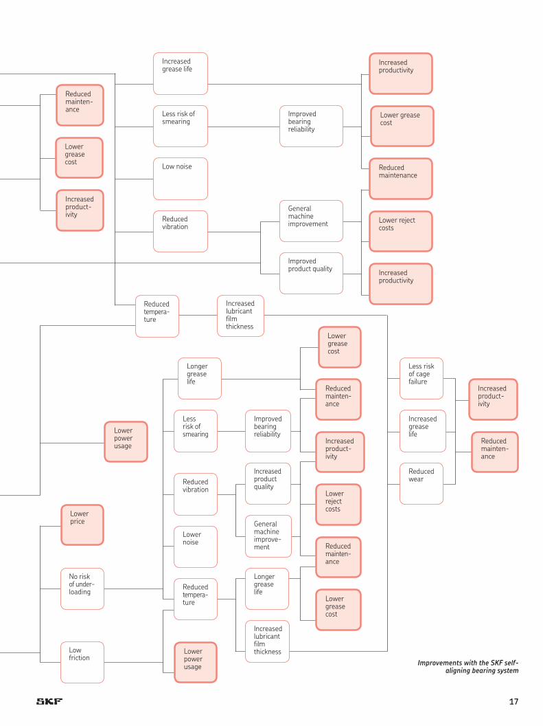
Improvements with the SKF self-aligning bearing system
17
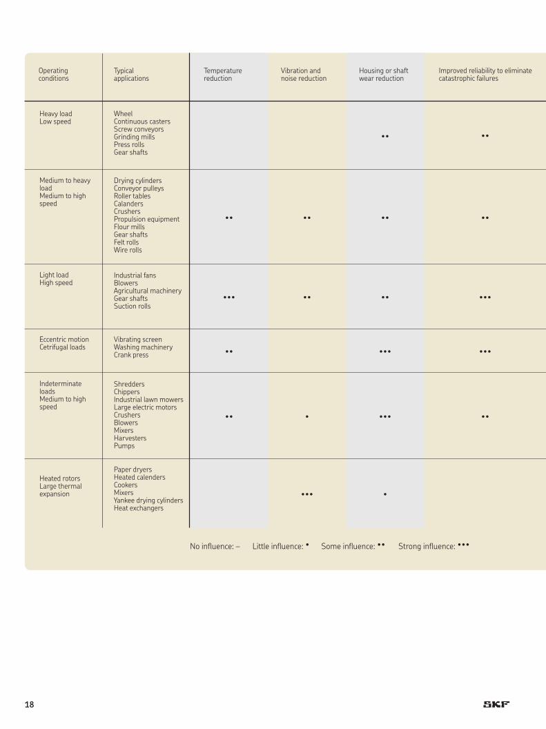
Operating conditions
Typical applications
Temperature reduction
Vibration and noise reduction
Housing or shaft wear reduction
Improved reliability to eliminate catastrophic failures
Heavy loadLow speed
Medium to heavy loadMedium to high speed
Light loadHigh speed
Eccentric motionCetrifugal loads
Indeterminate loadsMedium to high speed
Heated rotorsLarge thermal expansion
Wheel Continuous castersScrew conveyorsGrinding millsPress rollsGear shafts
Drying cylindersConveyor pulleysRoller tablesCalandersCrushersPropulsion equipmentFlour millsGear shaftsFelt rollsWire rolls
Industrial fansBlowersAgricultural machineryGear shaftsSuction rolls
Vibrating screenWashing machineryCrank press
ShreddersChippersIndustrial lawn mowersLarge electric motorsCrushersBlowersMixersHarvestersPumps
Paper dryersHeated calendersCookersMixersYankee drying cylindersHeat exchangers
No influence: – Little influence: · Some influence: ·· Strong influence: ···
··
·· ·· ··
··
··
··· ·· ·· ···
·· ··· ···
·· · ··· ··
··· ·
18
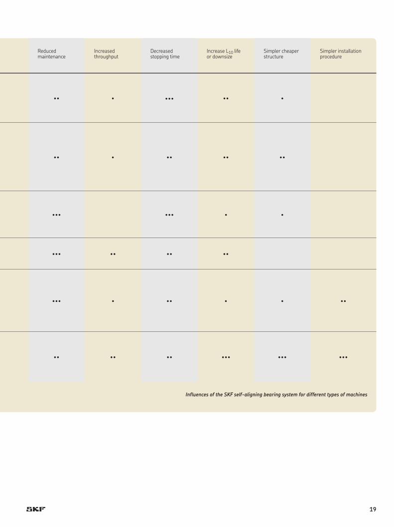
Reduced maintenance
Increased throughput
Decreased stopping time
Increase L10 life or downsize
Simpler cheaper structure
Simpler installation procedure
Influences of the SKF self-aligning bearing system for different types of machines
·· · ··· ·· ·
·· · ·· ·· ··
··· ··· · ·
··· ·· ·· ··
··· · ·· · · ··
·· ·· ·· ··· ··· ···
19
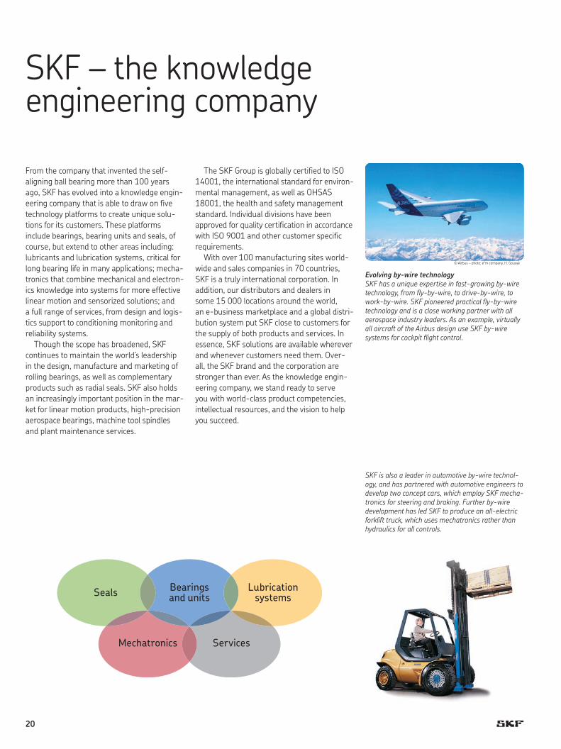
Evolving by-wire technology SKF has a unique expertise in fast-growing by-wire technology, from fly-by-wire, to drive-by-wire, to work-by-wire. SKF pioneered practical fly-by-wire technology and is a close working partner with all aerospace industry leaders. As an example, virtually all aircraft of the Airbus design use SKF by-wire systems for cockpit flight control.
SKF – the knowledge engineering company
From the company that invented the self-align ing ball bearing more than 100 years ago, SKF has evol ved into a knowledge engin-eering company that is able to draw on five technology platforms to create unique solu-tions for its custom ers. These platforms include bearings, bearing units and seals, of course, but extend to other areas including: lubricants and lubrication sys tems, critical for long bearing life in many appli cations; mecha-tronics that combine mech anical and electron-ics knowledge into systems for more effective linear motion and sensorized solutions; and a full range of ser vices, from design and logis-tics support to con ditioning monitoring and reliability systems.
Though the scope has broadened, SKF continues to maintain the world’s leadership in the design, manufacture and marketing of rolling bearings, as well as complementary products such as radial seals. SKF also holds an increasingly important position in the mar-ket for linear motion products, high-precision aerospace bearings, machine tool spindles and plant maintenance services.
© Airbus – photo: exm company, H. Goussé
The SKF Group is globally certified to ISO 14001, the international standard for enviro n-mental management, as well as OHSAS 18001, the health and safety manage ment standard. Individual divisions have been ap proved for quality certification in ac cord ance with ISO 9001 and other customer specific requirements.
With over 100 manufacturing sites world-wide and sales companies in 70 countries, SKF is a truly international corporation. In addition, our distributors and dealers in some 15 000 locations around the world, an e-business marketplace and a global distri-bution system put SKF close to customers for the supply of both products and services. In essence, SKF solutions are available wherever and whenever customers need them. Over - all, the SKF brand and the corporation are stronger than ever. As the knowledge engin-eering company, we stand ready to serve you with world-class product competencies, intellectual resources, and the vision to help you succeed.
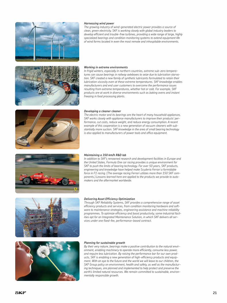
Bearings and unitsSeals Lubrication
systems
Mechatronics Services
SKF is also a leader in automotive by-wire technol-ogy, and has partnered with automotive engin eers to develop two concept cars, which employ SKF mecha -tronics for steering and braking. Further by-wire develop ment has led SKF to produce an all-electric forklift truck, which uses mecha tronics rather than hydraulics for all controls.
20
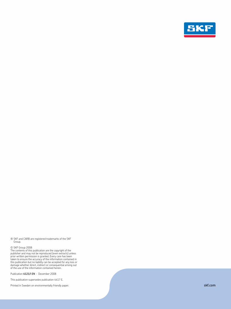
Developing a cleaner cleanerThe electric motor and its bearings are the heart of many household appliances. SKF works closely with appliance manufacturers to improve their products’ per-formance, cut costs, reduce weight, and reduce energy consumption. A recent example of this cooperation is a new generation of vacuum cleaners with sub-stantially more suction. SKF knowledge in the area of small bearing technology is also applied to manufacturers of power tools and office equipment.
Harnessing wind powerThe growing industry of wind-generated electric power provides a source of clean, green electricity. SKF is working closely with global industry leaders to develop efficient and trouble-free turbines, providing a wide range of large, highly specialized bearings and condition monitoring systems to extend equipment life of wind farms located in even the most remote and inhospitable environments.
Working in extreme environmentsIn frigid winters, especially in northern countries, extreme sub-zero tempera-tures can cause bearings in railway axleboxes to seize due to lubrication starva-tion. SKF created a new family of synthetic lubricants formulated to retain their lubrication viscosity even at these extreme temperatures. SKF knowledge enables manufacturers and end user customers to overcome the performance issues resulting from extreme temperatures, whether hot or cold. For example, SKF products are at work in diverse environments such as baking ovens and instant freezing in food processing plants.
Maintaining a 350 km/h R&D labIn addition to SKF’s renowned research and development facilities in Europe and the United States, Formula One car racing provides a unique environment for SKF to push the limits of bearing technology. For over 50 years, SKF products, engineering and knowledge have helped make Scuderia Ferrari a formidable force in F1 racing. (The average racing Ferrari utilizes more than 150 SKF com-ponents.) Lessons learned here are applied to the products we provide to auto-makers and the aftermarket worldwide.
Delivering Asset Efficiency Optimization Through SKF Reliability Systems, SKF provides a comprehensive range of asset efficiency products and services, from condition monitoring hardware and soft-ware to maintenance strategies, engineering assistance and machine reliability programmes. To optimize efficiency and boost productivity, some industrial facil-ities opt for an Integrated Maintenance Solution, in which SKF delivers all ser-vices under one fixed-fee, performance-based contract.
Planning for sustainable growth By their very nature, bearings make a positive contribution to the natural envir-onment, enabling machinery to operate more efficiently, consume less power, and require less lubrication. By raising the performance bar for our own prod-ucts, SKF is enabling a new generation of high-efficiency products and equip-ment. With an eye to the future and the world we will leave to our children, the SKF Group policy on environment, health and safety, as well as the manufactur-ing techniques, are planned and implemented to help protect and preserve the earth’s limited natural resources. We remain committed to sustainable, environ-mentally responsible growth.
21


® SKF and CARB are registered trademarks of the SKF Group.
© SKF Group 2008The contents of this publication are the copyright of the publisher and may not be reproduced (even extracts) unless prior written permission is granted. Every care has been taken to ensure the accuracy of the information contained in this publication but no liability can be accepted for any loss or damage whether direct, indirect or consequential arising out of the use of the information contained herein.
Publication 6121/I EN · December 2008
This publication supersedes publication 4417 E.
Printed in Sweden on environmentally friendly paper. skf.com