Embed Size (px)
Citation preview

7/23/2019 The Size Effect of Rock Sample Used in Anchorage Performance Test
http://slidepdf.com/reader/full/the-size-effect-of-rock-sample-used-in-anchorage-performance-test 1/10
University of Wollongong
Research Online
Ca) O#a/' C+$##+!# Fa!) $ E+%+##+% a+" I+$*a+ S!#+!#/
2014
Te size eect of rock sample used in anchorageperformance testing of cable bolts
Mahew HoldenUnivesity of New South Wales
Paul HaganUnivesity of New South Wales
R#/#a! O+)+# / # #+ a!!#// +/+a) #/ $ #
U+#/ $ W))+%+%. F $# +$*a+ !+a! # UOW
La: #/#a!-/@.#".a
P)!a+ D#a)/Ma# H)"#+ a+" Pa) Ha%a+, 7# /5# ##! $ !( /a*)# /#" + a+!a%# #$*a+!# #/+% $ !a)# )/, 14 Ca)O#a/' C+$##+!#, U+#/ $ W))+%+%, 7# A/a)a/a+ I+/# $ M++% a+" M#a))% & M+# Ma+a%#/ A//!a+
$ A/a)a, 2014, 128-136.
7/23/2019 The Size Effect of Rock Sample Used in Anchorage Performance Test
http://slidepdf.com/reader/full/the-size-effect-of-rock-sample-used-in-anchorage-performance-test 2/10
2014 Coal Operators’ Conference The Universi ty of Wol longo ng
128 12 – 14 February 2014
THE SIZE EFFECT OF ROCK SAMPLE USED IN ANCHORAGE
PERFORMANCE TESTING OF CABLE BOLTS
Matthew Holden
1
and Paul Hagan
ABSTRACT : This paper outlines the results of a study into the effect of rock specimen size on theanchorage performance of a hollow strand bulbed cable bolt. As part of the design of a Laboratory ShortEncapsulation Pull Test (LSEPT) facility, a question arose as to the appropriate size of the rock samplein which the cable bolt is embedded and whether size might affect the pull out strength of the cable bolt. An analysis of previous research revealed little information regarding the rationale for the sample sizeused in previous test work. Many of pull out tests in the past had made use of either a rigid encasmentsuch as steel, aluminium, or PVC casing or a biaxial pressure cell to apply a constant stress to modelthe in situ rock mass conditions.
A test arrangement was developed to assess whether there was any appreciable change in anchorageperformance with varying diameter of the rock sample. Cable bolts were embedded into the rock sample
using a polyester resin grout having diameters of 150 mm, 215 mm, 300 mm and 450 mm with aconstant embedment length of 280 mm. A hollow hydraulic ram was used to load the cable bolts tofailure.
The results indicate there was a size effect albeit only marginal whereby an increase in the diameterresulted in increased anchorage capacity of the cable bolt.
INTRODUCTION
Cable bolting is widely utilised in ground support of surface and underground excavations in both miningand civil engineering applications. Since they were first used in the 1970s, a wide variety of cable boltconfigurations and geometries have been developed. The performance of cable bolts has been found to
be is affected by parameters that include:
borehole diameter;
embedment length;
borehole radial confinement conditions;
cable bolt configurations and geometry; and
grout type and quality (Hutchinson and Diederichs, 1996).
The failure mechanism of cable bolting systems is complex and a function of loading conditions and theinteraction between the cable bolt, grout and rock mass. There are four general mechanisms of cable
bolt failure each of which is il lustrated in Figure 1.
Failure at the cable-grout interface, indicated as Mode (ii) in Figure 1, is considered the most commonfailure mechanism identified in the field (Hyett, et al ., 1996; Hyett, et al., 1995; Hutchinson andDiederichs, 1996; Rajaie, 1990; Singh, et al., 2001). This usually results from insufficient frictionalresistance between the ridges on the cable strands and the grout material. A combination of poor groundconditions and lack of quality control at the time of installation may also affect the bond strengths at theinterfaces that in turn can lead to premature failure of the system before the capacity of the cable bolt isactually achieved. Hence a standardised testing methodology should be designed such that failure ofthe system is more likely to occur at the cable-grout interface (Rajaie, 1990; Hutchinson and Diederichs,1996).
A comprehensive review of the testing methodologies revealed that while there are a number of testing
methods that have the potential to become the standard for pull out tests, there is no standardised oruniversally accepted suggested method with which to assess the strength of the wide range of cable
1 The University of New South Wales (UNSW), Sydney, Email: [email protected], Tel: 0419 018 998

7/23/2019 The Size Effect of Rock Sample Used in Anchorage Performance Test
http://slidepdf.com/reader/full/the-size-effect-of-rock-sample-used-in-anchorage-performance-test 3/10
2014 Coal Operators’ Conference The Universi ty of Wol longo ng
12 –14 February 2014 129
bolts that are available to industry. Essentially there are two approaches that have been adopted in thepast in the design of a testing facility these being either a constant stiffness system where the material inwhich the cable bolt is embedded is encased in a steel of other rigid tube or pipe such as thedouble-embedment test or, a constant load system where the material is placed within a pressurisedbiaxial cell.
Figure 1 - Schematic illustration of the four modes of load transfer related failure in cable bolts(Thomas, 2012)
Following a recent analysis of various pull out testing arrangements it was concluded the LaboratoryShort Encapsulation Pull Test (LSEPT) as developed by Clifford et al. (2001) and reported by Thomas(2012) is the most appropriate method to test the extensive range of cable bolts available. One of thekey advantages of the LSEPT is that one end of thecable bolt is embedded in a cylinder of material ascan be seen in Figure 2. In other tests the cable bolt is embedded in a rigid or semi-rigid casing such asa steel tube in the double embedment test which acts to constrain any lateral dilation. On axial loading,cable bolts activate some level of lateral dilation stress in a rock mass as part of the load transferprocess which can influence the magnitude and distribution of stress within the rock mass. The level ofthis dilation varies with the different cable bolt designs. There is little published information howeverabout the size effects of the material cylinder at the cable bolt/grout, grout/rock and rock containmentinterfaces during testing and consequently on the load/deformation characteristics and ultimate loadachieved by the cable bolt. Hence in developing a standard test method it is important to determine theminimum size of cylindrical block that will not affect the anchorage performance of a cable bolt.
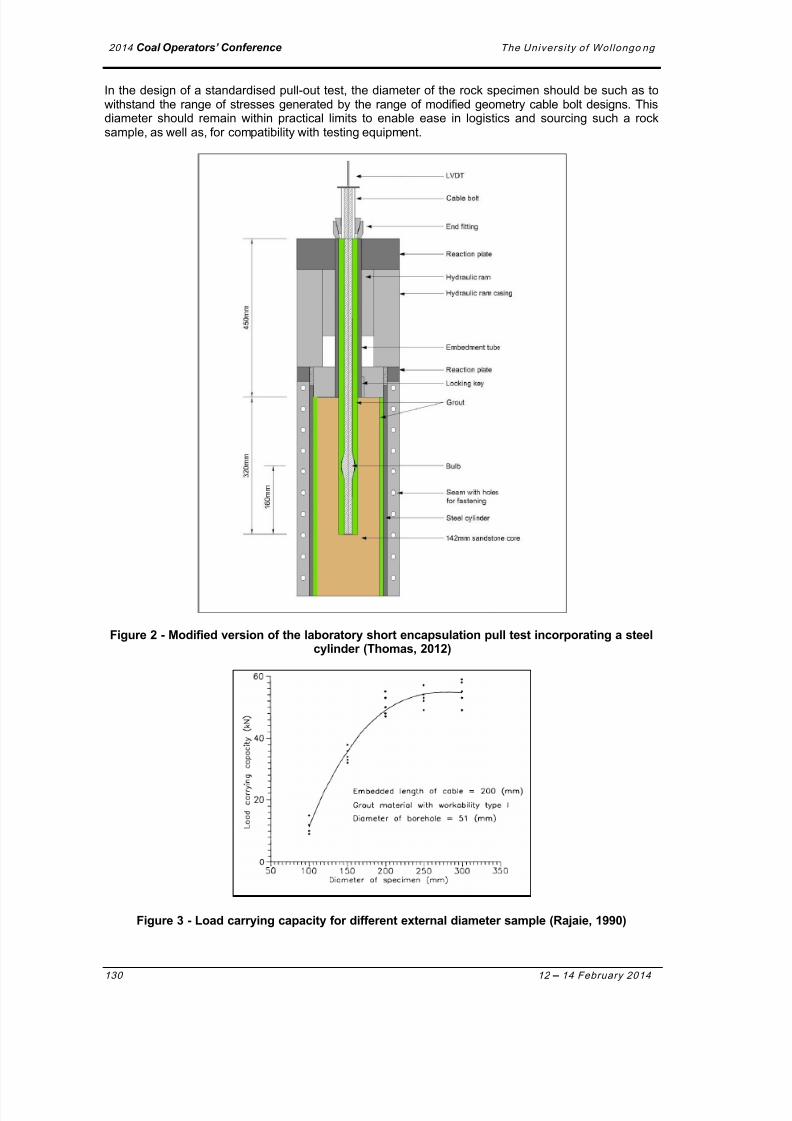
A study by Rajaie (1990) reported a link between the anchorage strength of a cable bolt and thediameter of the rock sample surrounding the grouted cable bolt. It was found that there was little changein load carrying capacity of the cable bolt with a specimen diameter in excess of 250 mm as can be seenFigure 3. This study however only involved a plain strand cable bolt that was in common use at that time.It therefore needs to be confirmed whether the same limit applies to the modified cable bolts nowavailable such as bulbed and birdcage bolts. The newer type cable bolts are likely to induce higherlateral stresses during failure requiring a larger rock mass to deal with the dilation generated by the bolt.
(i) Failure at
Cable to Grout
Interface
(ii) Failure
through Grout
Column
(iii) Failure at
Grout to Rock
Interface
(iv) Failure through
Rock Around
Borehole Wall
7/23/2019 The Size Effect of Rock Sample Used in Anchorage Performance Test
http://slidepdf.com/reader/full/the-size-effect-of-rock-sample-used-in-anchorage-performance-test 4/10
2014 Coal Operators’ Conference The Universi ty of Wol longo ng
130 12 – 14 February 2014
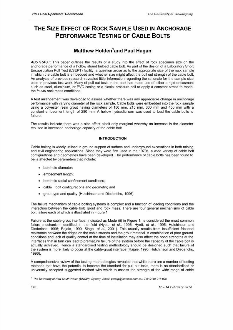
In the design of a standardised pull-out test, the diameter of the rock specimen should be such as towithstand the range of stresses generated by the range of modified geometry cable bolt designs. Thisdiameter should remain within practical limits to enable ease in logistics and sourcing such a rocksample, as well as, for compatibility with testing equipment.
Figure 2 - Modified version of the laboratory short encapsulation pull test incorporating a steelcylinder (Thomas, 2012)
Figure 3 - Load carrying capacity for different external diameter sample (Rajaie, 1990)
7/23/2019 The Size Effect of Rock Sample Used in Anchorage Performance Test
http://slidepdf.com/reader/full/the-size-effect-of-rock-sample-used-in-anchorage-performance-test 5/10
2014 Coal Operators’ Conference The Universi ty of Wol longo ng
12 –14 February 2014 131
EXPERIMENTAL PROCEDURE
Test specimen preparation
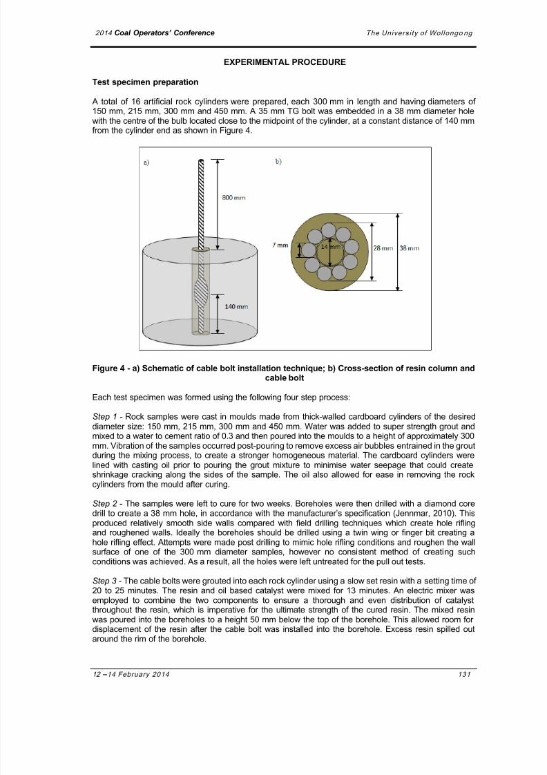
A total of 16 artificial rock cylinders were prepared, each 300 mm in length and having diameters of150 mm, 215 mm, 300 mm and 450 mm. A 35 mm TG bolt was embedded in a 38 mm diameter hole
with the centre of the bulb located close to the midpoint of the cylinder, at a constant distance of 140 mmfrom the cylinder end as shown in Figure 4.
Figure 4 - a) Schematic of cable bolt installation technique; b) Cross-section of resin column andcable bolt
Each test specimen was formed using the following four step process:
Step 1 - Rock samples were cast in moulds made from thick-walled cardboard cylinders of the desireddiameter size: 150 mm, 215 mm, 300 mm and 450 mm. Water was added to super strength grout andmixed to a water to cement ratio of 0.3 and then poured into the moulds to a height of approximately 300mm. Vibration of the samples occurred post-pouring to remove excess air bubbles entrained in the groutduring the mixing process, to create a stronger homogeneous material. The cardboard cylinders werelined with casting oil prior to pouring the grout mixture to minimise water seepage that could createshrinkage cracking along the sides of the sample. The oil also allowed for ease in removing the rockcylinders from the mould after curing.
Step 2 - The samples were left to cure for two weeks. Boreholes were then drilled with a diamond coredrill to create a 38 mm hole, in accordance with the manufacturer’s specification (Jennmar, 2010). Thisproduced relatively smooth side walls compared with field drilling techniques which create hole riflingand roughened walls. Ideally the boreholes should be drilled using a twin wing or finger bit creating ahole rifling effect. Attempts were made post drilling to mimic hole rifling conditions and roughen the wallsurface of one of the 300 mm diameter samples, however no consistent method of creating suchconditions was achieved. As a result, all the holes were left untreated for the pull out tests.
Step 3 - The cable bolts were grouted into each rock cylinder using a slow set resin with a setting time of20 to 25 minutes. The resin and oil based catalyst were mixed for 13 minutes. An electric mixer wasemployed to combine the two components to ensure a thorough and even distribution of catalystthroughout the resin, which is imperative for the ultimate strength of the cured resin. The mixed resin
was poured into the boreholes to a height 50 mm below the top of the borehole. This allowed room fordisplacement of the resin after the cable bolt was installed into the borehole. Excess resin spilled outaround the rim of the borehole.
7/23/2019 The Size Effect of Rock Sample Used in Anchorage Performance Test
http://slidepdf.com/reader/full/the-size-effect-of-rock-sample-used-in-anchorage-performance-test 6/10
2014 Coal Operators’ Conference The Universi ty of Wol longo ng
132 12 – 14 February 2014
Step 4 - Immediately following pouring of the resin into the hole, the cable bolt was spun, by hand, intothe borehole to ensure complete encapsulation of the bolt, and particularly to infuse the bulb and hollowstrand with resin. To ensure centrality of the bolt in the borehole and to maintain a constant embedmentlength of 280 mm, with the bulb located 140 mm from the top of the borehole, a simple frame wasattached to the bolt using L-shaped brackets. Later examination of the samples showed the low viscosityof the resin enabled it to penetrate inside the bulb of the cable bolt as well as the central hollow strand. A
cross-sectional schematic of the 5 mm thick resin annulus surrounding the bolt can be seen in Figure 4b.The final specimen with embedded cable bolt can be seen in Figure 4a, with the free end of the cablebolt extending 800 mm from the face of the rock cylinder to enable sufficient length to be secured by theloading machine.
Pull out test arrangement
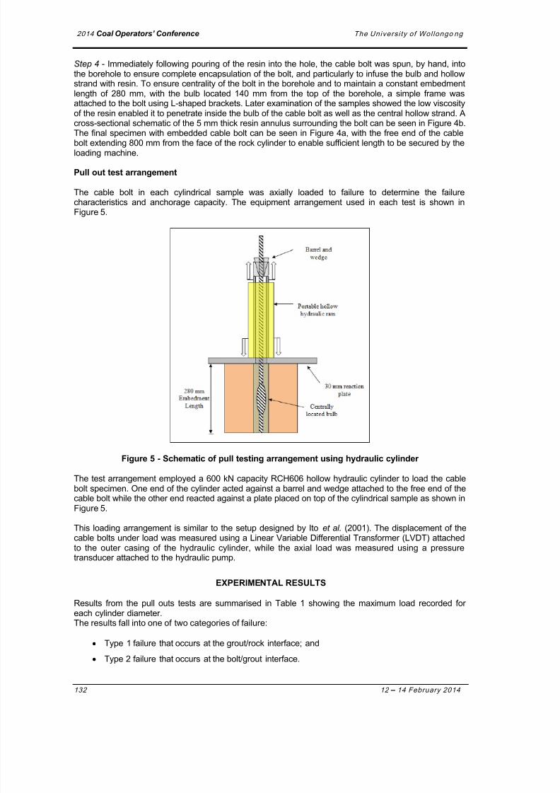
The cable bolt in each cylindrical sample was axially loaded to failure to determine the failurecharacteristics and anchorage capacity. The equipment arrangement used in each test is shown inFigure 5.
Figure 5 - Schematic of pull testing arrangement using hydraulic cylinder
The test arrangement employed a 600 kN capacity RCH606 hollow hydraulic cylinder to load the cablebolt specimen. One end of the cylinder acted against a barrel and wedge attached to the free end of thecable bolt while the other end reacted against a plate placed on top of the cylindrical sample as shown in
Figure 5.
This loading arrangement is similar to the setup designed by Ito et al. (2001). The displacement of thecable bolts under load was measured using a Linear Variable Differential Transformer (LVDT) attachedto the outer casing of the hydraulic cylinder, while the axial load was measured using a pressuretransducer attached to the hydraulic pump.
EXPERIMENTAL RESULTS
Results from the pull outs tests are summarised in Table 1 showing the maximum load recorded foreach cylinder diameter.The results fall into one of two categories of failure:
Type 1 failure that occurs at the grout/rock interface; and
Type 2 failure that occurs at the bolt/grout interface.

7/23/2019 The Size Effect of Rock Sample Used in Anchorage Performance Test
http://slidepdf.com/reader/full/the-size-effect-of-rock-sample-used-in-anchorage-performance-test 7/10

7/23/2019 The Size Effect of Rock Sample Used in Anchorage Performance Test
http://slidepdf.com/reader/full/the-size-effect-of-rock-sample-used-in-anchorage-performance-test 8/10
2014 Coal Operators’ Conference The Universi ty of Wol longo ng
134 12 – 14 February 2014
the shear forces at the artificial rock-grout interface could not have generated the level of stressesnecessary to fracture the samples.
Figure 7 - Evidence of radial tension cracking across all rock cylinder diameters
Further analysis of these findings revealed two possible mechanisms that might be responsible for theinconsistency between the observed peak failure loads as well as the apparent contradiction ofobserved radial tension cracking and the lack of evidence for radial dilation:
1. The resin-grout column slowly failed along the smooth rock-grout interface, requiring relativelylow loads to overcome shear resistance along this boundary. However, the grout column'smovement is constrained by the small size of hole in the steel reaction or bearing plate placedbetween the top of the cylinder and hydraulic ram, this being smaller than the diameter of theborehole.
This resulted in the grout being compressed causing dilation of the grout due to the Poissoneffect and thereby increasing the radial stress in the surrounding rock. This caused the sampleto fail in a manner similar to the pull out tests revealed in previous research through radialtension cracking (Rajaie, 1990; Ito, et al., 2001). A schematic of arrangement is illustrated inFigure 8.
2. The resin grout column failed in a similar manner described in 1) however the induced stressedin the surrounding rock are generated by moment forces being transferred through the groutcolumn.
Eccentric loading conditions at the point of contact between the hole in the steel plate and thegrout annulus are generated by slight misalignment of the resin column and the hole.
This results in moment forces acting on the borehole walls as the grout column pivots aroundthe steel plate contact point on the edge of the hole. This is illustrated in Figure 9.
CONCLUSIONS
The single embedment length unconstrained pull out tests found a slight increase in cable boltanchorage capacity with size of the cylindrical block sample containing the cable bolt.
In three tests where there was failure at the cable bolt/grout interface, which included two 150 mmdiameter specimens and one 450 mm sample, anchorage capacity of the cable bolt increased withdiameter of the cylinder used in the tests. The peak load achieved with the two smaller diametercylinders was approximately 110 kN while the larger cylinder achieved a peak load of 140 kN.
Of the remaining tests, 13 samples failed along the rock/grout interface. It is unlikely that the failuremechanisms in this instance is representative of the expected in situ failure conditions due in part to the

7/23/2019 The Size Effect of Rock Sample Used in Anchorage Performance Test
http://slidepdf.com/reader/full/the-size-effect-of-rock-sample-used-in-anchorage-performance-test 9/10
2014 Coal Operators’ Conference The Universi ty of Wol longo ng
12 –14 February 2014 135
relatively smooth surface of the borehole and confinement of the grout caused by the steel loading plateduring loading.
Figure 8 - Schematic of resin column dilation inducing sample failure
Figure 9 - Schematic of eccentric loading failure mechanism
ACKNOWLEDGEMENTS
The authors would like to thank Peter Craig and Jennmar for supplying the cable bolts tested in theinvestigation and providing much valued consultation, Lynda Laidler and JLok for supplying the slow setpolyester resin and Kanchana Gamage for his assistance in the laboratory.
REFERENCES
Clifford, B, Kent, L, Altounyan, P and Bigby, D, 2001. Systems used in coal mining development in long
tendon reinforcement, in Proceedings 20th International Conference on Ground Control in Mining ,7-9 August, Morgantown, USA.

7/23/2019 The Size Effect of Rock Sample Used in Anchorage Performance Test
http://slidepdf.com/reader/full/the-size-effect-of-rock-sample-used-in-anchorage-performance-test 10/10
2014 Coal Operators’ Conference The Universi ty of Wol longo ng
136 12 – 14 February 2014
Hutchinson, D J and Diederichs, M S, 1996. Cablebolting in Underground Mines, Richmond, Canada,(BiTech Publishers).
Hyett, A J, Bawden, W F, Macsporran, G R and Moosavi, M, 1995. A constitutive law for bond failure offully-grouted cable bolts using a modified Hoek cell, International Journal of Rock Mechanics andMining Sciences and Geomechanics Abstracts, 32(1):11-36.
Hyett, A J, Moosavi, M and Bawden, W F, 1996. Load distribution along fully grouted bolts, with
emphasis on cable bolt reinforcement, International Journal for Numerical and Analytical Methodsin Geomechanics, 20(7):517-544.Ito, F, Nakahara, F, Kawano, R, Kang, S and Obara, Y, 2001. Visualization of failure in a pull -out test of
cable bolts using x-ray CT, Construction and Building Materials, 15(5 –6):263-270.Jennmar, 2010, TG bolt features, Jennmar [online]. Available from: <http://www.jennmar.com.au/>
[Accessed: 12 September 2013].Rajaie, H, 1990. Experimental and numerical investigations of cable bolt support systems, PhD thesis,
Montreal, Canada, McGill University.Singh, R, Mandal, P K, Singh, A K and Singh, T N, 2001. Cable-bolting-based semi-mechanised
depillaring of a thick coal seam, International Journal of Rock Mechanics and Mining Sciences,38(2):245-257.
Thomas, R, 2012. The load transfer properties of post-groutable cable bolts used in the Australian coalindustry, in Proceedings 31st International Conference on Ground Control in Mining , 12 July,
Morgantown, USA.