Embed Size (px)
Citation preview
- -
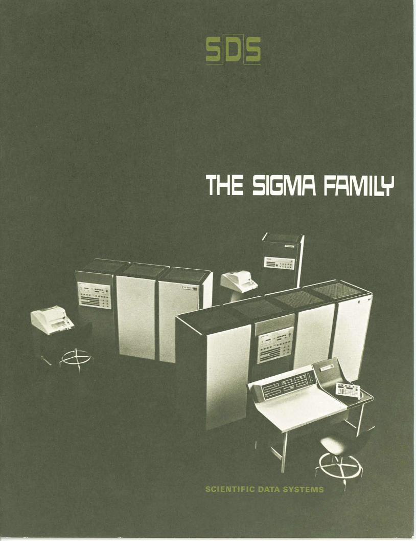
Introducing Sigma from Scientific Data Systems: A family of three high-performance, small to medium-size computers with nanosecond hardware and powerful software - for multi-use in a real-time environment.
SIGMA 2, the smallest member of the family, is designed for real-time processing with concurrent general-purpose operations in the background.
SIGMA 5, a medium-size computer, simultaneously performs multiple real-time operations while solving general-purpose problems in the background and controlling concurrent high- speed input/output operations.
-
SIGMA 7, the largest computer in the Sigma family, is specifically designed for real-time operations in a time-sharing environment. It can simultaneously perform real-time, conver- sational time-sharing, general-purpose, and high-speed input/output operations, individually or in any combination.
Sigma computers are ideally suited to a wide range of applications which require fast computation, concurrent input/output operations, and high volume throughput. The ad- vanced hardware design uses monolithic integrated circuits for improved performance and greater reliability.
To realize the advantages of Sigma hardware, SDS provides advanced software, including operating systems, FORTRAN IV compilers, assemblers, and other programming systems. Sigma software meets or exceeds appropriate industry standards to provide necessary com- patibility and lower programming costs.
Above all, Sigma computers offer an extraordinary combination of performance and economy to meet the needs of today while providing for future growth.
The SIGMA Concept
Traditionally, computers in the small to medium-size class were designed for a single application such as scientific computing, business data processing, or real-time control. For each of these applications, a separate machine was required. As the technology advanced, computers were developed to perform several of these jobs by switching from one application to another in sequence.
With the introduction of Sigma computers, both real-time sys- tems control and general-purpose operations can be performed at the same time. Providing this multi-use capability requires sig- nificant advances in both hardware and software.
Sigma software includes operating systems that give first pri- ority to processing real-time control programs in the foreground while remaining computer capacity is used to perform general- purpose operations in the background. Special hardware features permit Sigma computers to switch efficiently between these two kinds of work at very high speeds. Multi-port memories signifi- cantly increase system throughput capability.
To store the large programming systems provided with Sigma systems without a sharp increase in hardware memory costs, SDS has developed its Rapid-Access Data (RAD) file. The RAD pro- vides high performance and large capacity at the low cost associ- ated with ordinary disc files. And because one read/write head per track is used, rather than a movable head shared among many tracks, the RAD eliminates long access delays and provides the high data transfer rates and reliability required for real-time appli- cations. For off-line storage of RAD information, SDS offers both high-speed and low-cost magnetic tape units.
SlGMA 5 and SIGMA 7
Sigma 5 and Sigma 7 are specifically de- signed for high-speed multi-use in a real-time environment. In addition, Sigma 7 simul- taneously performs interactive time sharing with many users at remote sites.
Sigma 7 offers greater speed and time- sharing capability; Sigma 5 offers lower cost. Both machines were designed using the same basic concepts including similar hardware and software building blocks. The modular Sigma hardware design permits easy field expansion by adding memory, input/output processors, peripheral devices, and central processor options.
A Sigma 5/7 system consists of one or more core memories, a central processing unit, and input/output processors (IOPs). In Sigma 7, one to eight external IOPs provide greater speed through overlap of computa- tion and input/output. In Sigma 5, an integral IOP, which time-shares CPU hardware, is standard; up to eight external IOPs can be added for greater capacity.
- . troller is assigned its own channel and chain of 1/0commands.
~~~h selector IOP can handle any one of up to 32 high-speed device controllers at rates approaching the full speed of the core memory. Multiple selector IOPs can operate concurrently into separate memory banks on independent memory buses. A pair of selec- tor IOPs can share a common memory bus if desired.
The flexible Sigma 1/0 structure permits both data chaining (for scatter-read and gather-write operations) and command chaining (for multiple record operations without intervening CPU control).
In addition to channel operations through the IOPs, Sigma allows for direct input/output of a full word without the use of a channel. This is especially useful for asynchronous medium-speed 1/0operations frequently en- countered in special systems applications.
Multiple ports in each independent mem- ory permit many high-speed 1/0operations to proceed at the same time. With multiple memories and buses, up to five selector IOPs can be running at full speed at the same time, with a total throughput of up to five million words per second.
MEMORY Memory cycle time is 850 nanoseconds.
For maximum efficiency in dealing with the most commonly encountered data sizes, the Sigma word is 32 bits plus a parity bit. The total memory is directly addressable within the primary instruction word, precluding the need for base registers.
Core memory is expandable from 4,096 words to 131,072 words in increments of 4,096 words. For precise matching to the user's problem requirements, 32 different memory configurations are available.
For Sigma 7, if more than one core mem- ory module is used, memory overlap occurs automatically for all processors whenever possible. For Sigma 5, such overlap occurs between all external 1/0processors. To fur-ther improve the probability of overlap, Sig- ma permits interleaving of addresses, which increases the effective speed of the total computer system.
and temporary As an Op-tion, blocks of 16 general-purpose registers can be added to increase the total number to 256 in Sigma 5 and 512 in Sigma 7.
MEMORY WRITE PROTECTION To insure system integrity, an optional set
of registers in the CPU can be used to store a set of memory write protection codes, which can be changed only when the computer is in the master mode.
ADDRESSING In addition to direct addressing of the en-
tire memory, Sigma permits indirect ad-dressing, which can also be indexed. When indexing is used, the index register automat- ically scales itself according to the size of the data involved for easier programming. For example, if the selected index register contains a 27, an indexed Load Byte instruc- tion automatically loads the 27th byte; an indexed Load Word instruction automatically loads the 27th word, etc. This permits a single index register to be used to access the Kth element of an array, regardless of the type of elements in the array, without the need to perform complex index register calculations.
A selected set of instructions uses imme- diate addressing in which the operand is contained in the instruction itself to save space and time.
CONTEXT SWITCHING When the system switches from one user
to another or when it responds to a priority interrupt, the entire current program status can be stored and new status loaded, using a single instruction with an execution time of less than six microseconds. I INSTRUCTION FORMAT
For ease of use, Sigma uses a single in- struction format. For greater speed, the en- tire instruction is accessed at one time.
When the effective address is 0 through 15, the system references one of the general registers rather than memory. This permits all instructions to operate as register-to-regis- ter, with indexing and indirect addressing if desired.
The large instruction repertoires for Sigma 5 and Sigma 7 include a full set of logical op- erations (AND, OR, EOR) ;shift operations of words or doublewords, in logical, circular, arithmetic, and optional floating-point modes, either left or right; and multiple reg- ister operations (multiple load, store, push, and pull). Four Call instructions permit up to 64 dynamically variable monitor services or user-defined functions. PRIORITY INTERRUPTS
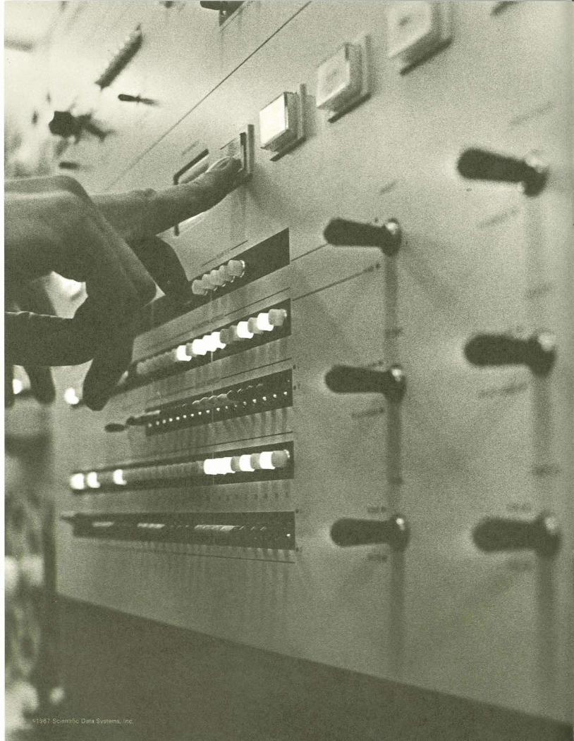
The priority interrupt system is an im-proved version of the system used in SDS 900 Series computers. Up to 224 levels of external interrupt are available. Each level has a unique address assigned in core and a unique priority. Hardware automatically han- dles and identifies the priority, and no spe- cial programming is required.
Each interrupt level can be individually armed and/or enabled for further flexibility. Assignment of priorities among blocks of in- terrupts is also flexible. The Sigma interrupt system permits any interrupt to be triggered under program control, which allows special system programs to be checked out before the special equipment is actually attached to the computer.
In Sigma 7, instructions with extended ex- ecution times are designed so that they are interruptible during their execution.
SIGMA 5 and 7 Software
To realize the advantages of the high-perfor- mance Sigma hardware, SDS provides ad- vanced software that includes operating systems, FORTRAN compilers, assemblers and a complete package of business soft- ware. This comprehensive array of modular software expands in capability and speed as a system grows, without reprogramming.
Because Sigma programming systems au- tomatically perform many routine functions, the user is free to concentrate on the prob- lem to be solved. As a result, user program- ming costs are sharply reduced.
SDS software employs advanced program- ming techniques to minimize storage require- ments and operating time, and to produce highly efficient object code. For medium and large configurations, the software makes full use of the advanced SDS RAD (Rapid-Access Data) file to increase throughput.
In addition to a basic programming pack- age, Sigma allows users to select higher-level and intermediate-level programming lan-guages, many with features unique to SDS.
OPERATING SYSTEMS Basic Control Monitor Designed for real- time systems with concurrent general-pur- pose processing, the Basic Control Monitor permits simultaneous operation of a real-time foreground problem and a general-purpose background process which can be indepen- dent of or related to the real-time problem.
Batch Processing Monitor The Batch Pro- cessing Monitor is a natural superset of the Basic Control Monitor. Designed for a typical production environment in which many jobs are being processed from a job queue, Batch Processing Monitor permits background and foreground operation simultaneously with many concurrent buffered peripheral opera- tions (Symbionts) . Univei.sal Time Sharing Monitor For Sigma 7, there is also an operating system specifi- cally designed to efficiently control conver- sational time sharing. It handles all of Batch Monitor capabilities as well as automatic swapping to or from secondary storage, ter- tiary mass storage control, and tasking in a time-sharing environment. It provides for multiple users in a variety of modes: batch, conversational, real-time, etc., and permits multi-use of common re-entrant processes. For example, only one copy of the FOR- TRAN compiler is loaded to support all the users who need FORTRAN service concur-
rently. Both swapping time and monitor over- head time are reduced significantly.
COMPILERS FORTRAN IV-H Exceeds ASA specifica- tions for FORTRAN IV. It is compatible with the compilers for other large-scale computers.
SDS FORTRAN IV A compatible superset of FORTRAN IV-H. It provides a large number of important additional language features. The debug mode of SDS FORTRAN IV places special emphasis on diagnostic error- checking of user programs. The high-effi- ciency mode of SDS FORTRAN IV uses advanced compilation techniques to produce highly efficient object code. For example, DO loops are optimized.
A Conversational FORTRAN IV is also provided for time-sharing applications.
ASSEMBLERS Symbol Accepts symbolic input from vari- ous media and translates standard SDS Sig- ma mnemonics and symbolic expressions into machine language.
Meta-Symbol A compatible superset of Symbol, Meta-Symbol provides additional capability including Functions and Proce- dures. It is a powerful tool for developing software systems for any object computer.
BUSINESS SOFTWARE SDS COBOL-65 COBOL provides a conve- nient, and widely accepted programming lan- guage for business applications. The language specifications conform to proposed ASA standards. They include the SORT verb, a Report Writer, and a Table Handling feature.
140I Simulator A 1401 Simulator package minimizes the problems associated with converting 1401, 1440 and 1460 programs.
Sort/Merge The generalized SDS Sort/ Merge package uses improved techniques based on the high performance SDS Rapid- Access Data file for fast sorting and merging.
ADDITIONAL PROGRAMS System Interface Unit Software Mainte-nance software for the standard off-the-shelf system interface units includes analog cali- bration and checkout programs, which oper- ate under a stand-alone diagnostic control program. Standard analog and digital input/ output handlers are provided.
Programming Systems Library More than 230 utility and mathematical programs are available in this library.
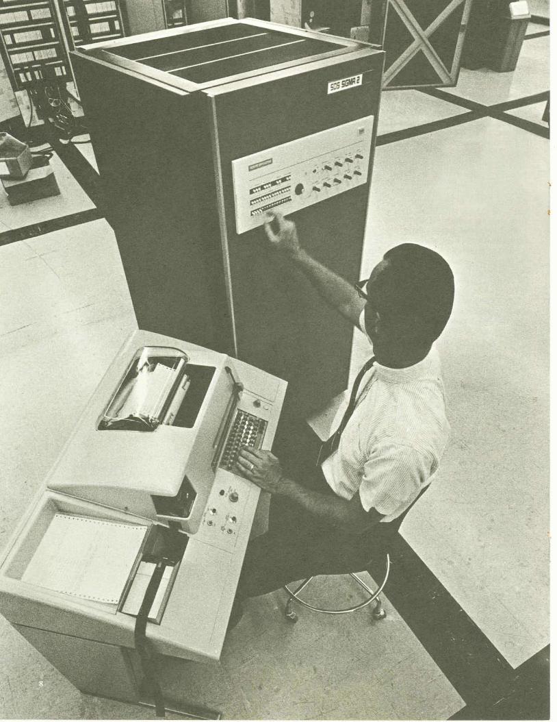
SIGMA 2
Sigma 2 is a low-cost computer designed to handle both real-time and general-purpose applications -concurrently. It is data and input/output compatible with the larger Sigma 5 and Sigma 7 computers and uses the same peripheral devices and standard inter- face units.
INPUT/OUTPUT Sigma 2 provides four fully automatic, buf-
fered input/output channels as standard equipment. Up to 16 additional automatic channels as well as direct input-output capa- biity can be added at low cost. Maximum 1/0 transfer rate exceeds 400,000 8-bit bytes per second.
Three distinct Sigma 2 input/output sys- tems offer sac ien t flexibility and capacity to meet the needs of both real-time and gen- eral-purpose users.
BYTE-ORIENTED SYSTEM Each automatic 1/0channel has its own
high-speed control registers and operates in- dependently without requiring attention from the program once it has been started. Data is transferred one byte at a time (8 bits plus parity).
DIRECT-TO-CPU INPUT/OUTPUT SYSTEM The Sigma 2 direct-to-CPU input/output
system uses only a single instruction to trans- fer a full 16-bit data word to/from the A reg-ister. The same instruction that transfers data also provides a 16-bit control field for exter- nal control and selection and accepts status information returned from the external de- vice to permit rapid sensing of an external condition.
DIRECT-TO-MEMORY INPUT/OUTPUT SYSTEM This system provides up to five additional
memory buses to each of four external mem- ories. Each of these memories can be per- forming input/output independently and simultaneously for maximum throughput. The direct-to-memory 1/0 system is used for high-speed 1/0 transfers to/from external devices or other Sigma processors.
MEMORY Memory cycle time is 900 nanoseconds.
For the most efficient operation as a small- scale computer, Sigma 2 word length is 16 bits plus a parity bit.
Sigma 2 memory is available in 16 diier- ent sizes from 4,096 to 65,536 16-bit words. Sigma 2 can also connect directly to a Sigma 5/7 memory system.
CENTRAL PROCESSING UNIT The CPU consists of an arithmetic and
control unit, and a block of high-speed reg-isters. It executes instructions and controls all input/output operations.
SYSTEM PROTECTION REGISTERS Sixteen optional registers of 16 bits each
are provided with the system protection feature. Each bit in this array indicates the protection status for a 256-word page of memory. This approach offers two advan- tages to the user: lower cost than the bit- per-word system used in other machines and faster changes to the protection status of the computer.
GENERAL REGISTERS The general registers are used for program
control information and are identified below.
Name Function
Z Zero. Reserved for CPU use. Its ad- dress can be used as a source of zeros in Copy instruction.
P Program Address Register L Link Address Register; used for re-
entrant subroutines T Temporary Storage Register X1 Index Register 1 X2 Index Register 2 (and Base Register) E Extended Accumulator; for multiple
precision operations A Accumulator
ADDRESSING Indexing and indirect addressing may be
used individually or together. All Sigma 2 memory-reference instructions are single word for greater efficiency in the use of pro- gram storage. Each instruction can directly reference 1024 addresses.
Sigma 2's relative addressing is always re-lated to the current location of the instruction rather than to fixed pages. Sigma 2 can ad- dress both forward and backward over a large span of 256 words in either direction. As the program proceeds, it continually moves into new areas of memory where the internal tables and data needed for opera- tion of that portion of the program may be stored.
In actual practice, a given program seg- ment uses relative addressing (forward or backward) for branching within itself and for accessing its own operands and tables easily and quickly, with only a single-word instruc- tion.
SIGMA 2 Software
Sigma 2 programming systems (both as- semblers and compilers) automatically han- dle assignment of the appropriate addressing mode to produce efficient code. The pro- grammer is thereby freed to concentrate on the problem itself.
RAPID CONTEXT SWITCHING When responding to a priority interrupt,
Sigma 2 must first preserve the current oper- ating environment and then rapidly establish the new environment with a minimum of overhead. Sigma 2 can switch contexts in less than four microseconds to provide con- current foreground-background processing with true real-time interrupt response.
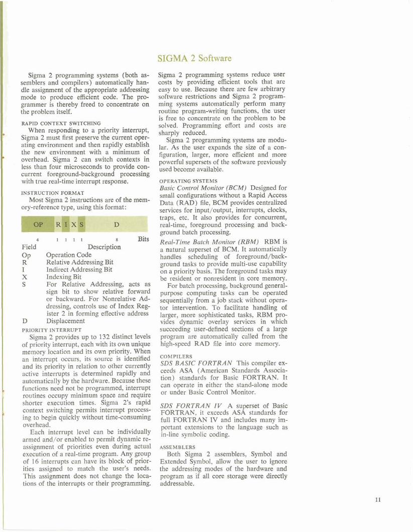
INSTRUCTION FORMAT Most Sigma 2 instructions are of the mem-
ory-reference type, using this format:
4 1 1 1 1 8 Bits Field Description OP Operation Code R Relative Addressing Bit I Indirect Addressing Bit X Indexing Bit S For Relative Addressing, acts as
sign bit to show relative forward or backward. For Nonrelative Ad- dressing, controls use of Index Reg- ister 2 in forming effective address Displacement
PRIORITY INTERRUPT Sigma 2 provides up to 132 distinct levels
of priority interrupt, each with its own unique memory location and its own priority. When an interrupt occurs, its source is identified and its priority in relation to other currently active interrupts is determined rapidly and automatically by the hardware. Because these functions need not be programmed, interrupt routines occupy minimum space and require shorter execution times. Sigma 2's rapid context switching permits interrupt process- ing to begin quickly without time-consuming overhead.
Each interrupt level can be individually armed and/or enabled to permit dynamic re- assignment of priorities even during actual execution of a real-time program. Any group of 16 interrupts can have its block of prior- ities assigned to match the user's needs. This assignment does not change the loca- tions of the interrupts or their programming.
Sigma 2 programming systems reduce user costs by providing efficient tools that are easy to use. Because there are few arbitrary software restrictions and Sigma 2 program- ming systems automatically perform many routine program-writing functions, the user is free to concentrate on the problem to be solved. Programming effort and costs are sharply reduced.
Sigma 2 programming systems are modu- lar. As the user expands the size of a con- figuration, larger, more efficient and more powerful supersets of the software previously used become available.
OPERATING SYSTEMS Basic Control Monitor (BCM) Designed for small configurations without a Rapid Access Data (RAD) file, BCM provides centralized services for input/output, interrupts, clocks, traps, etc. It also provides for concurrent, real-time, foreground processing and back- ground batch processing. Real-Time Batch Monitor (RBM) RBM is a natural superset of BCM. It automatically handles scheduling of foreground/back-ground tasks to provide multi-use capability on a priority basis. The foreground tasks may be resident or nonresident in core memory.
For batch processing, background general- purpose computing tasks can be operated sequentially from a job stack without opera- tor intervention. To facilitate handling of larger, more sophisticated tasks, RBM pro- vides dynamic overlay services in which succeeding user-defined sections of a large program are automatically called from the high-speed RAD file into core memory.
COMPILERS SDS BASIC FORTRAN This compiler ex- ceeds ASA (American Standards Associa- tion) standards for Basic FORTRAN. It can operate in either the stand-alone mode or under Basic Control Monitor.
SDS FORTRAN IV A superset of Basic FORTRAN, it exceeds ASA standards for full FORTRAN IV and includes many itn-portant extensions to the language such as in-line symbolic coding.
ASSEMBLERS Both Sigma 2 assemblers, Symbol and
Extended Symbol, allow the user to ignore the addressing modes of the hardware and program as if all core storage were directly addressable.
SIGMA Systems
The SDS data systems group has extensive experience in the design and manufacture of real-time, on-line, and special-purpose com- puter-based systems. This experience is re- flected in the design of Sigma computers and systems devices.
To deal with the wide variety of informa- tion formats encountered, a successful real- time system requires special hardware and software in addition to an efficient systems- oriented computer. SDS offers an extensive array of system interface units (SIUs) for all Sigma computers. These standard, modular units connect analog and digital devices to the computer while fully exploiting Sigma's advanced input/output features.
Standard SIUs available for Sigma systems include:
Analog Input Controller, which provides the interface and control necessary to oper- ate an analog-to-digital converter and a high- speed multiplexer through an 8-bit 1/0 channel. The controller permits random or sequential sampling of analog inputs at pre- specified intervals. Any number of these con- troller units can be added to a Sigma system.
Analog Output Controller, which provides the interface and control necessary to oper- ate from one to 16 digital-to-analog channel controllers through an 8-bit 1/0 channel. Each channel controller can operate five to 16 digital-to-analog converters. The unit al-lows analog outputs to be controlled ran- domly, sequentially, or simultaneously. Any number of these controller units can be added to a Sigma system.
IOP-to-DIO Adapter, which transforms any Sigma 8-bit 1/0channel into an interface identical to the Sigma Direct 1/0Interface. The adapter unit enables users to perform a program-specified number of 32-bit direct input or output operations, in any combina- tion, with the 8-bit 1/0channel. Any number of these controller units can be added to a Sigma system.
Digital 1/0 Subsystem, which generates pulsed digital outputs, transfers data in mem- ory to output registers, stores input signals in memory, and provides latched relay drive signals. Each fully expanded unit accommo- dates any combination of 8-bit stored output
groups, 8-bit relay drive groups, 16-bit pulsed output groups, or 16-bit input groups up to total of 60 groups. One to four units can be added to a Sigma system via the direct 1/0 interface.
Analog and Digital Adapter, which pro- vides the interface and control circuitry to operate one analog-to-digital converter, one analog multiplexer, and one or two digital-to- analog channel controllers on Direct I/O. This unit generates pulsed digital outputs, transfers data in memory to output registers, and stores the states of input lines in memory. One unit can be attached to a Sigma system via the direct 1/0interface.
Frequency Control Subsystem, which pro- vides frequency control of analog input, ana- log output, and digital transfer control units, causing external devices to perform opera- tions at prespecified intervals. Each fully ex- panded unit furnishes four frequency sources. The frequency of each source can be speci- fied manually or by the program. One or two of these units can be used in a Sigma system.
Because SIUs are standard equipment, they satisfy individual system requirements with-out the need for special engineering. User benefits include lower cost, ease of system design, ease of maintenance, extensive docu- mentation, and greater flexibility as system needs change. System interface units are handled in the same easy-to-use manner as all SDS peripheral equipment and have stand- ard software. During checkout, a special operating system is generated which provides configuration identification and 1/0data han- dling in standard form for system interface units. SIU maintenance software includes analog calibration and checkout programs and digital input/output programs.
In addition, SDS produces a complete line of analog/digital instruments and modules for interfacing Sigma computer systems with a wide range of real-time environments.
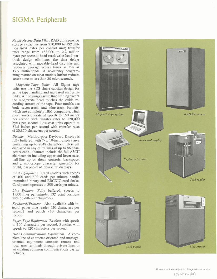
SIGMA Peripherals
Rapid-Access Data Files. RAD units provide storage capacities from 750,000 to 192 mil-lion 8-bit bytes per control unit; transfer rates range from 188,000 to 2.2 million bytes per second; fixed read/write head-per- track design eliminates the time delays associated with movable-head disc files and produces average access times as low as 17.5 milliseconds. A no-latency program- ming feature on most models further reduces access time to less than 30 microseconds.
Magnetic-Tape Units All Sigma tape units use the SDS single-capstan design for gentle tape handling and increased unit relia- bility. Air bearings assure that nothing except the read/write head touches the oxide re-cording surface of the tape. Four models use both seven-track and nine-track formats, which are completely IBM-compatible. High speed units operate at speeds to 150 inches per second with transfer rates to 120,000 bytes per second. Low-cost units operate at 37.5 inches per second with transfer rates of 20,850 characters per second.
Display Multipurpose Keyboard Display is fully buffered, with 7- x 10-inch display area containing up to 2048 characters. These are displayed in any of 32 lines of up to 86 char- acters each. Features include the full ASCII character set including upper and lower case, half-line up or down controls, backspace, and a monoscope character generator for bright, easy-to-read character displays.
Card Equipment Card readers with speeds of 400 and 800 cards per minute handle intermixed binary and EBCDIC card decks. Card punch operates at 300 cards per minute.
Line Printers Fully buffered, speeds to 1,000 lines per minute, 132 print positions with 56 different characters.
Keyboard/Printers Also available with in- tegral paper-tape reader (20 characters per second) and punch (10 characters per second.
Paper-Tape Equipment Readers with speeds to 300 characters per second. Punches with speeds to 120 characters per second.
Data Communications Equipment A com-plete line of character-oriented and message- oriented equipment connects remote and local user terminals through private lines or an existing common communications carrier network.
All spec~flcat~onssubject to change w~ thou t notlce.
\ o r n 4 ~ \ b O -I