Embed Size (px)
Citation preview

Engineering Structures 23 (2001) 756–767www.elsevier.com/locate/engstruct
The sensitivity of silo flow and wall stresses to filling method
Z. Zhong, J.Y. Ooi *, J.M. RotterSchool of Civil and Environmental Engineering, Division of Engineering, University of Edinburgh, Edinburgh EH9 3JN, UK
Received 14 August 1996; received in revised form and accepted 25 September 2000
Abstract
The pattern of solids flow during discharge of a silo and the pressures against the silo wall are commonly assumed to dependonly on the measurable properties of the solid, including its interaction with the silo wall. A small number of previous studies havenoted that the method of filling the silo may affect the flow pattern, generally altering it from mass to mixed flow. It has beensuggested that this change may be caused by altered mechanical properties of the solid. However, the significance of the fillingmethod for the practical design of silos has rarely been considered. In this experimental study, barley and plastic pellets were testedin a pilot scale aluminium silo with a flat bottom. The paper outlines the results of the experiments, in which flow pattern observationswere made from the top surface, and wall stresses were measured using strain gauges. The filling process is seen to have a markedeffect on the flow pattern and wall stresses found for plastic pellets, but very little effect on those for barley. The implications forsilo design are discussed briefly. 2001 Elsevier Science Ltd. All rights reserved.
Keywords: Bulk solids handling; Flow patterns; Filling; Discharge; Silos; Solids flow; Strains; Wall stresses
1. Introduction
It has long been recognised that the pattern of solidsflow in a silo has a strong influence on the pressuresexerted by the solid against the silo wall [1–3]. Thus thispattern has an important bearing on the structural integ-rity of the silo. The traditional view of simple flow pat-terns is shown in Fig. 1. Mass flow is the flow modewhere every particle of solid is in motion. In funnel flow,some of the solid is stationary and thus there is a “flowchannel boundary” between flowing and static solid.Funnel flow patterns may be divided into internal (pipe)flow and mixed (or semi-mass) flow. In mixed flow, the“effective transition” is the point at which the flow chan-nel boundary reaches the wall (Fig. 1).
Earlier studies of silo pressures have generally sug-gested that wall pressures are entirely symmetrical if thefilling and discharge are both symmetrical. The chief dis-tinction that has been thought necessary has beenbetween mass flow and funnel flow [4–6]. However,more recent work [7–9] has shown that a more important
* Corresponding author. Tel.: +44-131-650-5719; fax: +44-131-650-7170.
E-mail address: [email protected] (J.Y. Ooi).
0141-0296/01/$ - see front matter 2001 Elsevier Science Ltd. All rights reserved.PII: S0141- 02 96 (00)00 09 9- 7
Fig. 1. Classical flow patterns. (a) Mass flow; (b) Mixed flow, and(c) pipe flow.
distinction for the assessment of silo structural integritywhen the conditions are notionally symmetric is a dis-tinction between circumstances in which the pressuresare symmetrically distributed on the silo wall and thosein which a loss of symmetry occurs. Evidence of thisloss of symmetry in silo pressures may be seen in thebetter experimental studies of recent times [10–16]. Silopressure studies in which the symmetry of the pressures

757Z. Zhong et al. / Engineering Structures 23 (2001) 756–767
was not checked are difficult to interpret [1,2,4,17]because the reported measurements were generally madeon one vertical line down the silo wall, and these neitherrepresent the mean value nor the maximum, but simplydefine a single chance sample value at that particularheight.
When the pattern of solids flow is very eccentric, itis natural that the wall pressures become very unsym-metrical [1,14,18–20], and these are formally included insome design methods [19,20]. However, unsymmetricalpressures of significant magnitude can often be seenunder apparently symmetrical conditions [11–16] andmust also be accounted for in design [8,9]. The predic-tion of flow patterns should accordingly focus on thedistinction between patterns that induce strongly unsym-metrical pressures and those that cause only a minor lossof symmetry.
The simplest distinction between these two flow con-ditions (symmetric and asymmetric) is not the differencebetween mass and funnel flow, but that between differentforms of funnel flow. Whilst mass flow has been welldefined for a long time [3], differences between differentfunnel flow modes have been less clearly defined. Somestructural loading standards for silos now distinguishbetween internal flow and mixed flow [21], but they pro-vide no criteria to predict which will occur for givenconditions. The chief reason why the distinction isnecessary is that internal flow causes relatively littlechange in the wall pressures from filling to discharge,whilst the effective transition in a mixed flow silo isknown to be associated with high local pressures [15].A minor loss of symmetry in the flow pattern at theheight of the effective transition (Fig. 2) can cause aserious loss of symmetry in the wall pressures.
The pattern of solids flow in a silo and the pressuresagainst the silo wall are commonly assumed to dependon the measurable properties of the bulk solid alone[4,5,22], including its interaction with the silo wall. Theclassic study of Sugden [23] demonstrated the effect ofthe packing density of the bulk solid on flow patterns.A small number of later studies [15,24] have also notedthat the method of filling the silo may affect the flowpattern (presumably by changing the packing density),generally altering it from mass flow to mixed flow. Ithas usually been thought that a change in packing den-sity caused a change in the internal friction angle of thesolid [11], but the causal link to flow patterns has notbeen established. It may also be noted that the internalfriction angle is a poor predictor of the flow channelgeometry [25]. The consequences of the filling methodfor the design of practical silos have been almost univer-sally ignored (e.g. [4–6,21,26,27]).
This paper describes a set of experiments on the flowpatterns and wall stresses occurring in a pilot scalemodel silo storing plastic pellets and barley. The silo isthin-walled and made of aluminium and has a flat bot-
Fig. 2. Symmetrical and slightly unsymmetrical mixed flow. (a) Per-fectly symmetrical mixed flow, and (b) slightly unsymmetricalmixed flow.
tom. The plastic pellets are referred to as M1 pellets,being the first plastic pellets donated by Mainetti Ltd ofJedburgh, UK for this work. In these experiments, flowpattern observations were made from the top surface,and wall stresses were measured using strain gauges onthe silo wall. The many tests involved concentric, halfeccentric and fully eccentric discharge. The filling pro-cess is seen to have a marked effect on the flow patternand pressures found for M1 plastic pellets, but almostno effect on those for barley. This outcome differs con-siderably from the known comparable earlier studies[15].
2. Experimental silo
The experimental silo test facility is shown in Fig. 3.Bulk solids can be transferred between the storage siloand the test silo or re-circulated. All the tests describedhere involved only solids transfer (filling from empty;discharge until empty). The test silo is cylindrical withan independent flat bottom, and has an aspect ratio of4.05 (height 4.25 m; diameter 1.05 m). It is supportedon six load cells (permitting the total wall friction to bemeasured independently) from the top, so that bucklingproblems are avoided in the very thin wall. The supportarrangements were designed with great care to ensurethat the forces from the six discrete supports werequickly distributed evenly into the shell wall, so thatuneven stresses in the wall could be attributed with con-fidence to unsymmetrical solids pressures alone. For thesame reason, the bottom was independently supportedso that unsymmetrical pressures on the bottom could not

758 Z. Zhong et al. / Engineering Structures 23 (2001) 756–767
Fig. 3. Silo test facility.
induce stresses in the walls. The silo outlet was open atall times, and flow was arrested during filling by thesolid in the outlet bin. Discharge was initiated byoperating the solids handling equipment, which initiatedflow by removing the pile in the outlet bin.
The silo is extensively instrumented with straingauges at eight different levels. These levels are namedA through I (Level D omitted), and their heights abovethe silo floor are shown in Fig. 4. Strain gauges cannotbe used on the inside surface because they interfere withthe solids flow, can influence the local pressure distri-bution, and cause local bending of the wall [28] (becauseof the local pressures that arise on an internal bulge onthe wall [29]). In such conditions, strain gauging canbe undertaken using “sandwich” or “double deck” straingauges [28,30,31] on the external surface of the wall.However, these gauges cause a slight local stiffening ofthe wall [30,31], and because this silo wall is very thin,a decision was taken to use many closely spaced singlelayer gauges on the external surface and interpret theresults using recently developed sophisticated interpret-ative processes [32]. This paper describes the stressesmeasured in the silo walls, which is the final result ofthe solid’s action and the goal of silo analysis, but it also
offers a complete, uninterrupted and unprocessed imageof the behaviour.
Filling of the silo was achieved with two differentarrangements: concentric filling and distributed filling(Fig. 5). The solids were transferred from the storagesilo into the filling box, situated above the silo, whichwas itself concentrically filled. Under concentric filling,a single hole in the centre of the filling box of diameter1050 mm was used. Under distributed filling, 13 equallyspaced holes in the base of the filling box all dischargedsimultaneously, raining the particles onto the existingsurface and causing a flat top surface to within ±10 mm.Full details of the silo may be found elsewhere [33].
3. Silo tests
The tests described here were all conducted undersymmetrical conditions. Great care was taken to ensuresymmetry of the structure, support conditions, outletflow, wall friction, and filling process. Every experimentwas repeated at least once (but not as the very next test)to check for repeatability. These repeat tests indicatedthat all the behaviours reported here were reproducible,

759Z. Zhong et al. / Engineering Structures 23 (2001) 756–767
Fig. 4. Instrumentation levels.
Fig. 5. Filling patterns.
and insensitive to small property changes in the solidcaused by attrition.
The two solids were both free-flowing, had very smallfines contents and displayed no cohesion. The measuredproperties for M1 plastic pellets and barley, obtained
using a Jenike shear cell, are given in Table 1. Nocohesion was found for either solid.
Samples of solid were taken at different stages of thetest program and the wall friction was measured on apiece of the aluminium wall material itself using a Jeniketester. Slight changes occurred through the test series:the wall friction of M1 pellets gradually rose from 15°to 19°, whilst the wall friction angle of barley remainedmore stable at 13°, but a virgin sample of unused barleyhad a higher wall friction angle at 15°.
The form of the flow pattern was assessed by carefulmeasurement of the profile of the surface during dis-charge. These measurements were made at fixed timesduring the discharge using a plumb-bob technique inwhich all points are evaluated in rapid sequence and theprecise values recorded later. Whilst surface profilemeasurements are not as direct as residence time obser-vations [14], they are sufficient to identify the flowsquite well in this study. The relationship between pro-gressive surface profiles and the internal flow pattern isillustrated in Fig. 6 and Fig. 7.
The mixed flow mode (Fig. 7(b)) is more complicatedand was investigated further using a 650 mm diameterhalf-cylindrical silo in which visual flow pattern obser-vations can be made through the transparent diametralwall. The M1 pellets produced a mixed flow in the half-cylindrical model, with the boundary having a linear(conical) geometry with a cone apex half angle of 40°(Fig. 8(a)). The flow pattern remained quite stable untilthe solid surface fell to a height of about 1.2 times thediameter of the silo. As the surface fell from 1.2 to 1.1diameters, an annular section of the solid near the wallstopped moving and the flow channel narrowed down toan internal flow which was slightly convex with amaximum width at the top of approximately 400 mm(Fig. 8(b)). Since this half silo model is at almost thesame scale as the pilot scale model (650 mm vs 1050mm in diameter), the internal flow pattern observed inthe half model can be taken as representative of internalpatterns in the pilot scale model experiments. It may benoted that no known experimental technique can yettrack these changes within a full cylindrical silo at thisscale [14,34].
The results of eight pilot scale tests are outlinedbelow. The configurations of these tests are indicated inTable 2, involving the two different filling methodsapplied to barley and M1 pellets (four combinations,each of which was repeated).
4. Tests on M1 pellets
A total of 21 tests were performed on the M1 plasticpellets, covering three different eccentricities of dis-charge, the two simple filling methods defined above,and sequential mixtures of the two filling methods to
760 Z. Zhong et al. / Engineering Structures 23 (2001) 756–767
Table 1Properties of solids used in the tests
Solid Density loose kg/m3 Density maximum Internal friction angle Wall friction angle Particle size (mean)(vibrated) kg/m3 (mm)
M1 Plastic pellets 592 690 40° 15° 2×2×3 cylsBarley 691 780 29° 13° 8.1×3.6×2.7
Fig. 6. Flow patterns.
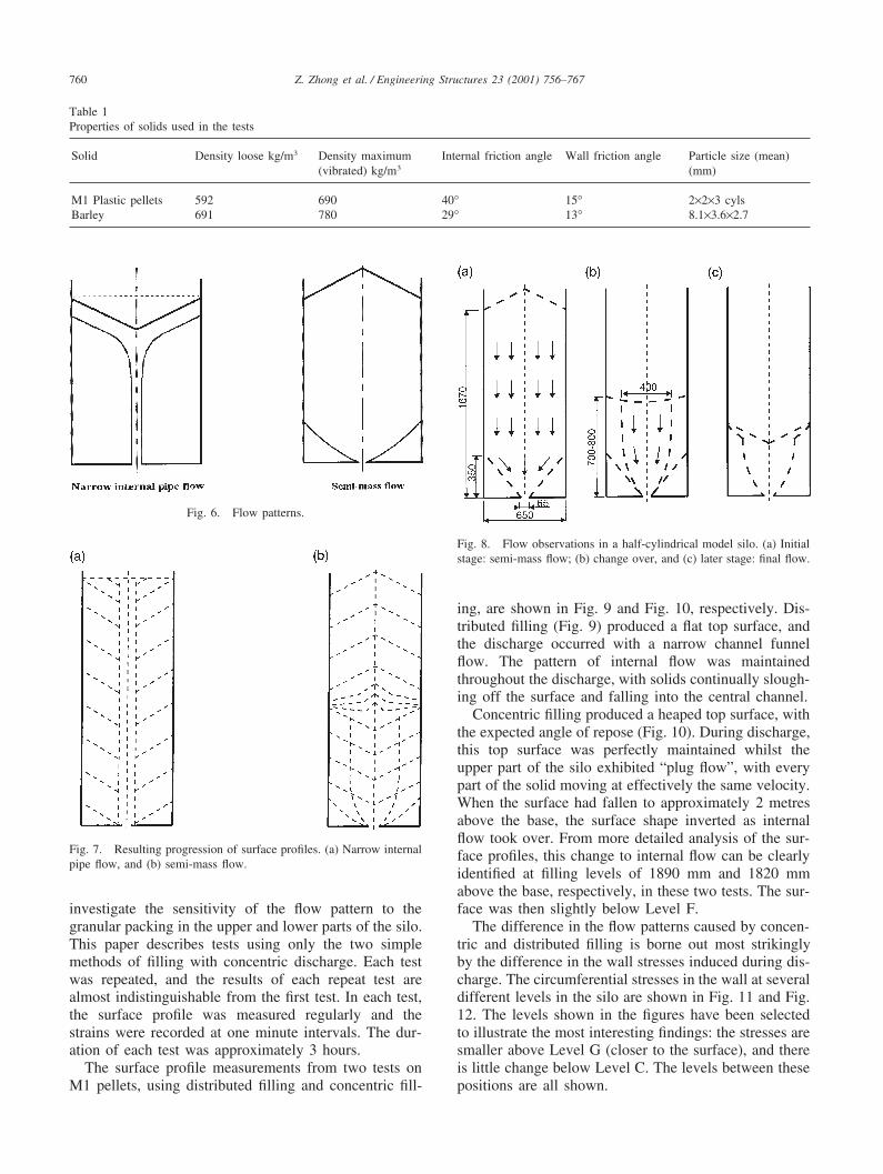
Fig. 7. Resulting progression of surface profiles. (a) Narrow internalpipe flow, and (b) semi-mass flow.
investigate the sensitivity of the flow pattern to thegranular packing in the upper and lower parts of the silo.This paper describes tests using only the two simplemethods of filling with concentric discharge. Each testwas repeated, and the results of each repeat test arealmost indistinguishable from the first test. In each test,the surface profile was measured regularly and thestrains were recorded at one minute intervals. The dur-ation of each test was approximately 3 hours.
The surface profile measurements from two tests onM1 pellets, using distributed filling and concentric fill-
Fig. 8. Flow observations in a half-cylindrical model silo. (a) Initialstage: semi-mass flow; (b) change over, and (c) later stage: final flow.
ing, are shown in Fig. 9 and Fig. 10, respectively. Dis-tributed filling (Fig. 9) produced a flat top surface, andthe discharge occurred with a narrow channel funnelflow. The pattern of internal flow was maintainedthroughout the discharge, with solids continually slough-ing off the surface and falling into the central channel.
Concentric filling produced a heaped top surface, withthe expected angle of repose (Fig. 10). During discharge,this top surface was perfectly maintained whilst theupper part of the silo exhibited “plug flow”, with everypart of the solid moving at effectively the same velocity.When the surface had fallen to approximately 2 metresabove the base, the surface shape inverted as internalflow took over. From more detailed analysis of the sur-face profiles, this change to internal flow can be clearlyidentified at filling levels of 1890 mm and 1820 mmabove the base, respectively, in these two tests. The sur-face was then slightly below Level F.
The difference in the flow patterns caused by concen-tric and distributed filling is borne out most strikinglyby the difference in the wall stresses induced during dis-charge. The circumferential stresses in the wall at severaldifferent levels in the silo are shown in Fig. 11 and Fig.12. The levels shown in the figures have been selectedto illustrate the most interesting findings: the stresses aresmaller above Level G (closer to the surface), and thereis little change below Level C. The levels between thesepositions are all shown.

761Z. Zhong et al. / Engineering Structures 23 (2001) 756–767
Table 2Tests on concentric discharge
Solid Test names Filling method Discharge Flow pattern
M1 pellets M1CCA, M1CCB Concentric Concentric MixedM1 pellets M1DCA, M1DCB Distributed Concentric InternalBarley BCCA, BCCB Concentric Concentric MixedBarley BDCA, BDCB Distributed Concentric Mixed
Fig. 9. Top surface profile for M1 pellets, distributed filling.
In Fig. 11 and Fig. 12, the time variation is shown ofthe circumferential stress at many different points aroundthe circumference at that level. The extent of the scatterindicates the extent of asymmetry in the silo’s responseto the pressures, but a high peak value does not necessar-ily correlate precisely with the change in pressure (forexample, a discharge stress reaching twice the fillingstress cannot be interpreted to mean that the local press-ure was twice the filling pressure: it could actually beeither lesser or greater than this, depending on the areaover which it acts).
The two filling methods induced similar wall stressesafter filling (Fig. 11 and Fig. 12), but the discharge wallstresses were very different. With internal flow (Fig. 11),the discharge wall stresses were barely detectable as dif-
Fig. 10. Top surface profile for M1 pellets, concentric filling.
ferent from the filling stresses. Some increases in stressdid occur high in the silo (illustrated by Level G).
By contrast, the same silo filled with the same M1pellets in a concentric manner displayed mixed flow(Fig. 10), with very much higher stresses throughout thewall, and stresses which varied rapidly with time. Thereadings shown in Fig. 12 were taken only once perminute, so the observed oscillations cannot be describedas vibration: the oscillations in each observation have arelatively well defined period of the order of 6 to 10minutes.
The highest stresses and the greatest variationoccurred at Level F. The variations at this level, withsome stresses rising markedly and others falling mark-edly, indicate a strong asymmetry of local pressures. The

762 Z. Zhong et al. / Engineering Structures 23 (2001) 756–767
Fig. 11. Wall circumferential stresses. Fig. 12. Wall circumferential stresses.
763Z. Zhong et al. / Engineering Structures 23 (2001) 756–767
fact that a high stress remains high throughout the dis-charge, whilst a low one remains low (with superim-posed oscillations) indicates that the asymmetry is in astable pattern around the circumference. Asymmetrichigh pressures at the effective transition level can affectthe wall stresses throughout the entire height of the silowall [8,9], usually with the strongest influence locallyand decaying towards the top and bottom of the wall.Thus, the increases and decreases in stress seen at otherlevels in the silo are not directly attributable to changesin wall pressure at these points. The oscillating charac-teristic permeates the stresses in the whole silo wall (Fig.12). Much additional information can be obtained fromthe vertical and shear stresses on the wall exterior sur-face, both of which were measured, but are not presentedin this first interpretation because of space limitations.
5. Tests on barley
A total of 15 tests were performed on barley, againincluding three different eccentricities of discharge, thetwo simple filling methods defined above, and a repeat
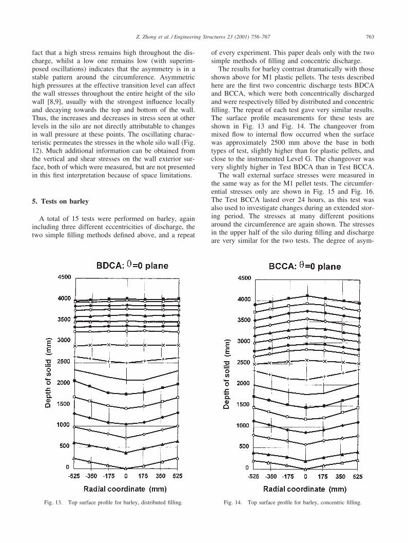
Fig. 13. Top surface profile for barley, distributed filling.
of every experiment. This paper deals only with the twosimple methods of filling and concentric discharge.
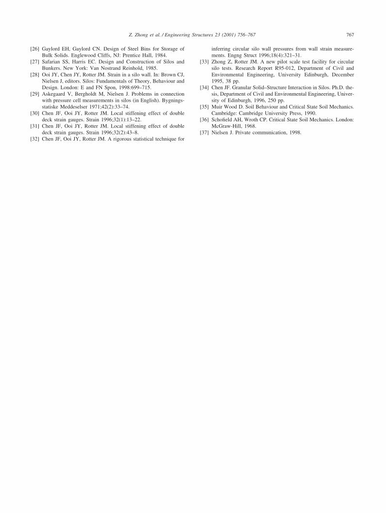
The results for barley contrast dramatically with thoseshown above for M1 plastic pellets. The tests describedhere are the first two concentric discharge tests BDCAand BCCA, which were both concentrically dischargedand were respectively filled by distributed and concentricfilling. The repeat of each test gave very similar results.The surface profile measurements for these tests areshown in Fig. 13 and Fig. 14. The changeover frommixed flow to internal flow occurred when the surfacewas approximately 2500 mm above the base in bothtypes of test, slightly higher than for plastic pellets, andclose to the instrumented Level G. The changeover wasvery slightly higher in Test BDCA than in Test BCCA.
The wall external surface stresses were measured inthe same way as for the M1 pellet tests. The circumfer-ential stresses only are shown in Fig. 15 and Fig. 16.The Test BCCA lasted over 24 hours, as this test wasalso used to investigate changes during an extended stor-ing period. The stresses at many different positionsaround the circumference are again shown. The stressesin the upper half of the silo during filling and dischargeare very similar for the two tests. The degree of asym-
Fig. 14. Top surface profile for barley, concentric filling.

764 Z. Zhong et al. / Engineering Structures 23 (2001) 756–767
Fig. 15. Wall circumferential stresses. Fig. 16. Wall circumferential stresses.

765Z. Zhong et al. / Engineering Structures 23 (2001) 756–767
metry and the highest stresses observed are both verysimilar. The highest stresses by far during dischargeoccur at Level F, which is also the case for M1 pelletsin mixed flow.
At positions on the wall well below Level F (LevelsE and C), the stress levels are noticeably differentbetween the two tests: those for distributed filling aremore affected by the discharge process than those forconcentric filling. This appears to be a reversal of thedifferences seen for M1 pellets, and possible expla-nations are not easily found.
6. Overview of the tests
The two tested materials show rather different flowpatterns and very different wall stresses when distributedfilling is used, but rather similar behaviour after concen-tric filling. The following explanation is consistent withall the observations and an understanding derived fromthe critical state theory granular mechanics, but furtherexperimentation is needed to prove it conclusively.
It is believed that concentric filling develops a ratherloose packing because most particles slide down theinclined surface and lodge in haphazard positions. Bycontrast, distributed filling means that every position inthe bed of particles is subjected to the impact energyof later falling particles, and a much denser structuredevelops. These density differences were observed byMunch-Andersen and Nielsen [15] and can also be seenin the present study.
For flow to occur, particles must pass each other anddisplay macroscopic shearing, and this requires the criti-cal density for the relevant stress level to be approached[35,36]. Thus, if a dense packing has been used, the solidmust dilate (particles become more widely separated) forflow to occur, but if the packing is loose, little dilationis needed. Dilation can only develop from the outlet, anda high dilation requirement means that only vertical ornearly vertical channels will develop, leading to internalpipe flow. A loose packing means that wide channelscan form, and the flow channel geometry can be con-trolled by the internal friction angle alone.
Thus, it is proposed here that the reason for the differ-ent flow channel geometries and consequently differentwall stresses in M1 pellets is that the density followingdistributed filling produces a dense packing structure thatrequires much dilation to flow. By contrast, it is believedthat the packing structure of barley grains is chiefly con-trolled by its shape, and that macroscopic shearing caneasily propagate through the mass by rotation of thegrains, leading to little restriction on flow channelgeometry as a result of dilation requirements. It isthought that the flow channel geometry is then governedby internal friction only.
Further tests on the dilation requirements for mass
flow in different materials have recently been conductedin Edinburgh, and these confirm the considerable differ-ences in dilation under flow between different solids andtheir sensitivity to initial packing structure.
One unexplained observation remains. Munch-And-ersen and Nielsen [15] found that although the flow ofwheat was insensitive to filling method (mixed flow forboth filling methods), barley showed internal flow underdistributed filling, but mixed flow under concentric fill-ing. These differences were entirely attributed to themean density achieved on filling, but barley evidentlybehaved differently in their tests (at similar scale) fromits behaviour here. It is possible that different grainmoisture contents, seed varieties, harvests, or grain sizescould have caused the differences, and this concept issupported by informal observations in a brewery siloreported by Nielsen [37].
However, it is evident that much more work on theeffect of the filling process is needed before these effectswill be fully understood.
7. Implications for practical design
It is clear that very minor changes to the filling pro-cess can lead to substantial changes in the flow patternand wall stresses when some solids are stored. Theidentification of which solids are sensitive to this effectand which are not will probably take a long time, sincethe phenomena cannot yet be made to occur at the willof the researcher. Until this work is undertaken, thepossibility that silos designed for internal flow maysometimes display mixed flow should always beincluded in the design process. This means that thehigher and unsymmetrical pressures arising in mixedflow should always be adopted for design, unless the silois so squat that mixed flow is not possible. Current codi-fied rules already adopt this idea, though for otherreasons, so no change in design practice is currentlyrequired. However, it is evident that it will be a challeng-ing task to develop robust predictive tools which willallow the lower pressure regimes of internal flow to befully exploited in practice.
8. Conclusions
Two solids have been tested in a pilot scale aluminiumsilo with a flat bottom: M1 plastic pellets and barley.Flow pattern observations were made from the top sur-face, and wall stresses were measured using straingauges. The filling process has been found to have amarked effect on the solids flow pattern and the wallstresses for M1 plastic pellets, but very little effect onthose for barley. The tests were all repeated and foundto be very closely reproducible.

766 Z. Zhong et al. / Engineering Structures 23 (2001) 756–767
The chief conclusions of these concentrically filledand discharged tests are:
1. Small changes in the filling process can have a verymarked effect on the solids flow pattern under con-centric conditions.
2. For some solids, internal flow can occur for distrib-uted filling, but mixed flow for concentric filling. Thismatches the observations of Munch-Andersen andNielsen [15].
3. For other solids, mixed flow occurs for both distrib-uted and concentric filling. This also matches theobservations of Munch-Andersen and Nielsen [15].
4. Barley was found to be in this second group. Thiscontrasts with the observation of Munch-Andersenand Nielsen [15], for whom barley was the exemplarof sensitivity to filling conditions.
5. It is believed that the reason for the sensitivity to fill-ing method lies in the dilation requirement for thesolid to pass from its packed density to the criticaldensity required for flow.
6. Where internal flow occurs, loss of symmetry in wallstresses is not significant and the wall stresses arerather similar to those for filling conditions.
7. Under mixed flow, great variation and marked asym-metry of the wall stresses occurs during discharge.This loss of symmetry is so strong that it is probablymore important than any symmetrical overpressure.
Acknowledgements
The work described in this paper was supported byGrant GR/G 59318 from the Process Engineering Com-mittee of the UK Engineering and Physical SciencesResearch Council whose support is gratefully acknowl-edged. The authors are most grateful to Mr Jim Taylorof Mainetti Ltd of Jedburgh for an extended loan of 3tonnes of M1 plastic pellets, and to the Scottish Agricul-tural College for the loan of 3 tonnes of barley. Theassistance of Dr Paul Berry with the silo design is noted.Special thanks are also recorded to Dr Jorgen Nielsenfor many discussions and much helpful advice on testinterpretations and experimental design.
References
[1] Ketchum MS. Design of Walls, Bins and Grain Elevators. 1st ed.New York: McGraw-Hill, 1907.
[2] Pieper K, Wenzel F. Comments on DIN1055: Design Loads forBuildings Loads in Silo Bins. Beton und Stahlbetonbau,1963:6-11.
[3] Jenike AW. Storage and Flow of Solids. Bulletin No. 123, UtahEngineering Experiment Station, University of Utah, Salt LakeCity, Utah, 1964, 197 pp.
[4] Jenike AW, Johanson JR, Carson JW. Bin Loads—Part 2: Con-cepts; Part 3: Mass Flow Bins; Part 4: Funnel Flow Bins. J Engngfor Industry, Trans ASME Series B 1973;95(1):1–16.
[5] Arnold PC, McLean AG, Roberts AW. Bulk Solids: Storage,Flow and Handling. Tunra Bulk Solids Handling ResearchAssociates, University of Newcastle, Australia, 1980.
[6] Roberts AW. 100 years of Janssen. In: Proceedings of the 3rdEuropean Symposium: Storage and Flow of Particulate Solids,Nurnberg, 21–23 March, 1995:7–44.
[7] Rotter JM, Pham L, Nielsen J. On the specification of loads forthe structural design of bins and silos. In: Proceedings of the 2ndInternational Conference on Bulk Materials Storage Handling andTransportation, Institution of Engineers, Australia, Wollongong,July, 1986:241–7.
[8] Rotter JM. Challenges for the future in the design of bulk solidstorages. In: Simpson B, editor. Containment Structures: Risk,Safety and Reliability. London: E. and F.N. Spon, 1997:11–34.
[9] Rotter JM. Flow and pressures in silo structural integrity assess-ments. In: Proceedings of the International Symposium: ReliableFlow of Particulate Solids III, Porsgrunn, Norway, August,1999:281–92.
[10] Nielsen J. Opmaling af Silo i Karpalund (in Danish). NordicGroup for Silo Research, Report No. 4, Technical University ofDenmark, Department of Structural Engineering, 1979, 21 pp.
[11] Hartlen J, Nielsen J, Ljunggren L, Martensson G, Wigram S. TheWall Pressure in Large Grain Silos. Document D2:1984, SwedishCouncil for Building Research, Stockholm, 1984.
[12] Schmidt KH, Stiglat K. Anmerkungen zur Bemessungslast vonSilos. Beton und Stahlbetonbau 1987;9:239–42.
[13] Ooi JY, Rotter JM, Pham L. Systematic and random features ofmeasured pressures on full-scale silo walls. Engng Struct1990;12(2):74–87.
[14] Rotter JM, Ooi JY, Chen JF, Tiley PJ, Mackintosh I, Bennett FR.Flow Pattern Measurement in Full Scale Silos. British MaterialsHandling Board, 1995, 230pp.
[15] Munch-Andersen J, Nielsen J. Pressures in slender grain silos.CHISA 1990, 2nd European Symposium on Stress and Strain inParticulate Solids, Prague, August, 1990, 9 pp.
[16] Nielsen J. Pressures from flowing granular solids in silos. PhilTrans Series A 1998;356:2667–84.
[17] Pieper K, Wenzel F. Druckverhaltnisse in Silozellen. Berlin: Ver-lag von Wilhelm Ernst und Sohn, 1964.
[18] Jenike AW. Denting of circular bins with eccentric drawpoints.J Struct Div, ASCE (ST1) 1967;93:27–35.
[19] Wood JGM. The analysis of silo structures subject to eccentricdischarge. In: Proceedings of the Second International Confer-ence on Design of Silos for Strength and Flow, Stratford-upon-Avon, 1983:132–44.
[20] Rotter JM. The analysis of steel bins subject to eccentric dis-charge. In: Proceedings of the 2nd International Conference onBulk Materials Storage Handling and Transportation, Institutionof Engineers Australia, Wollongong, July, 1986:264–71.
[21] ENV 1991-4: Eurocode 1: Basis of Design and Actions on Struc-tures, Part 4 — Silos and Tanks, Eurocode 1 Part 4. CEN, Brus-sels, 1995.
[22] Nedderman RM. Statics and Kinematics of Granular Materials.Cambridge: Cambridge University Press, 1992.
[23] Sugden MB. Effect of initial density on flow patterns in circularflat bottomed silos. In: Proceedings of the International Confer-ence on Design of Silos for Strength and Flow, University ofLancaster, September, 1980:11–28.
[24] Wright AWS. Silos —- model and field studies. Ph.D. thesis,University of Manchester, 1979, 480 pp.
[25] Carson JW, Goodwill DJ, Bengston KE. Predicting the shape offlow channels in funnel flow bins and silos. In: Proceedings ofthe ACI Convention, Boston, Massachussetts, March 1991, 12 pp.
767Z. Zhong et al. / Engineering Structures 23 (2001) 756–767
[26] Gaylord EH, Gaylord CN. Design of Steel Bins for Storage ofBulk Solids. Englewood Cliffs, NJ: Prentice Hall, 1984.
[27] Safarian SS, Harris EC. Design and Construction of Silos andBunkers. New York: Van Nostrand Reinhold, 1985.
[28] Ooi JY, Chen JY, Rotter JM. Strain in a silo wall. In: Brown CJ,Nielsen J, editors. Silos: Fundamentals of Theory, Behaviour andDesign. London: E and FN Spon, 1998:699–715.
[29] Askegaard V, Bergholdt M, Nielsen J. Problems in connectionwith pressure cell measurements in silos (in English). Bygnings-statiske Meddeselser 1971;42(2):33–74.
[30] Chen JF, Ooi JY, Rotter JM. Local stiffening effect of doubledeck strain gauges. Strain 1996;32(1):13–22.
[31] Chen JF, Ooi JY, Rotter JM. Local stiffening effect of doubledeck strain gauges. Strain 1996;32(2):43–8.
[32] Chen JF, Ooi JY, Rotter JM. A rigorous statistical technique for
inferring circular silo wall pressures from wall strain measure-ments. Engng Struct 1996;18(4):321–31.
[33] Zhong Z, Rotter JM. A new pilot scale test facility for circularsilo tests. Research Report R95-012, Department of Civil andEnvironmental Engineering, University Edinburgh, December1995, 38 pp.
[34] Chen JF. Granular Solid–Structure Interaction in Silos. Ph.D. the-sis, Department of Civil and Environmental Engineering, Univer-sity of Edinburgh, 1996, 250 pp.
[35] Muir Wood D. Soil Behaviour and Critical State Soil Mechanics.Cambridge: Cambridge University Press, 1990.
[36] Schofield AH, Wroth CP. Critical State Soil Mechanics. London:McGraw-Hill, 1968.
[37] Nielsen J. Private communication, 1998.