Embed Size (px)
Citation preview
Project Manual
Form Rev: 2019-July-01 Project Manual Cover - Page 1 of 1
UPGRADE CHILLER PLANT
PROJECT NO. 2047712
DELTONA LAKES ELEMENTARY
2022 ADELIA BLVD.
DELTONA, FL 32725
THE SCHOOL BOARD OF VOLUSIA COUNTY FLORIDA 200 NORTH CLARA AVENUE
DELAND, FLORIDA
MECHANICAL
SABISTON ENGINEERING GROUP, INC. 322 Kentucky Blue Circle Apopka, FL 32712
ELECTRICAL
MATERN PROFESSIONAL ENGINEERING, INC. 130 Candace Drive Maitland, FL 32751
DATE: 1/6/2020
REVISED:

TABLE OF CONTENTS SCHOOL BOARD OF VOLUSIA COUNTY FLORIDA
Form Rev: 2019-July-01 Table of Contents - Page 1 of 2
Facility Name: Deltona Lakes Elementary Project Name: Upgrade Chiller Plant VCS Project No.: 2047712
TITLE NO. OF PAGES
Cover Page 1
Table of Contents 2
Index of Drawings 1
DIVISION 0 BIDDING REQUIREMENTS, CONTRACT FORMS, CONDITIONS OF THE CONTRACT AND FORMS
DOC. NO. TITLE NO. OF PAGES
630 Advertisement for Bid 1
631 Instructions to Bidders 5
632 Bid Form 2
A310 Bid Bond Form (AIA Doc) 2
633 List of Subcontractors 1
634 Bidder Project Data Self-Perfomed Portions of Work 2
635 Trench Safety Act Form 1
636 Bid Protest Bond Form 2
A101-2017 Standard Form of Agreement - VCS Master 9
A101-2017 Exhibit A (Insurance and Bonds) 7
A201-2017 General Conditions of the Contract - VCS Master 48
625 N/A N/A
640 Performance and Payment Bond 2
641 Contractor’s Direct Material Purchase Affidavit 1
642 Contractor Acknowledgment Form (Asbestos Survey) 1
650 Notice to Proceed 1
G702 Application and Certification for Payment (AIA Doc) 1
G703 Application and Certification for Payment – Continuation Sheet (AIA Doc) 1
651 Architect’s Field Report 1
652 Architect’s Supplemental Instructions 1
653 Proposal Request 1
658 Change Order 2
G707A Consent of Surety to Reduction in or Partial Release of Retainage (AIA Doc) 1
660 Certificate of Substantial Completion 1
G707 Consent of Surety to Final Payment (AIA Doc) 1
661 Contractor Affidavit 1
662 Receipt and Release 1 Note: If this project is less than $100,000 replace the A101-2017 Standard Form of Agreement (VCS Master), A101-2017 Exhibit A and the A201-2017 General Conditions of the Contract with the 625 Standard Form of Agreement for a Small Project. Documents listed above may not apply to this particular project. Select “N/A” for document(s) which do not apply to this project. Consult the VCS Construction Project Manager in charge to make this determination.

Form Rev: 2019-July-01 Table of Contents - Page 2 of 2
Facility Name: Deltona Lakes Elementary Project Name: Upgrade Chiller Plant VCS Project No.: 2047712
(Insert remainder of specification sections below to complete the table of contents.)
DIVISION 1 - GENERAL REQUIREMENTS
01 73 03 Execution Requirements ......................................................................................... 15 01 73 29 Cutting and Patching ................................................................................................. 2 03 30 00 Cast in Place Concrete .............................................................................................. 7 09 91 00 Painting ...................................................................................................................... 4
DIVISION 23 - MECHANICAL
23 05 01 Mechanical General Requirements ........................................................................... 7 23 05 13 Common Motor Requirements for HVAC Equipment ............................................... 2 23 05 14 Variable Frequency Drives ........................................................................................ 9 23 05 29 Hangers and Supports for HVAC Piping and Equipment .......................................... 5 23 05 54 Mechanical Identification ........................................................................................... 2 23 05 93 Testing, Adjusting, and Balancing for HVAC ............................................................. 2 23 05 93.1 Contractor Assisted Testing, Adjusting, and Balancing for HVAC ............................ 2 23 07 13 Thermal Insulation ..................................................................................................... 6 23 08 02 Startup of Mechanical Systems ................................................................................. 6 23 09 33 VCSD Electric and Electronic Control Systems for HVAC ...................................... 28 23 21 14 HVAC Piping............................................................................................................ 10 23 21 23 Hydronic Pumps ........................................................................................................ 4 23 25 00 HVAC Water Treatment Systems.............................................................................. 4 23 64 26 Water Chillers – Air Cooled ..................................................................................... 12
DIVISION 26 - ELECTRICAL
26 01 00 Operation and Maintenance Manuals For Electrical ............................................... 10 26 01 03 Minor Electrical Demolition for Remodeling .............................................................. 2 26 01 05 Investigation of Existing Electrical Systems .............................................................. 3 26 05 00 Common Work Results for Electrical ...................................................................... 10 26 05 03 Equipment Wiring Systems ....................................................................................... 2 26 05 06 Demonstration of Completed Electrical Systems ...................................................... 3 26 05 07 Submittals .................................................................................................................. 6 26 05 08 Substitutions .............................................................................................................. 3 26 05 09 Reference Standards and Regulatory Requirements ............................................... 4 26 05 10 Electrical Symbols and Abbreviations ....................................................................... 4 26 05 19 Building Wire and Cable ............................................................................................ 5 26 05 26 Grounding and Bonding ............................................................................................ 8 26 05 29 Hangers and Supports .............................................................................................. 3 26 05 33 Conduit .................................................................................................................... 11 26 05 34 Outlet Boxes .............................................................................................................. 5 26 05 35 Pull and Junction Boxes ............................................................................................ 3 26 05 37 Surface Raceways .................................................................................................... 2 26 05 53 Identification for Electrical Systems .......................................................................... 4 26 08 13 Tests and Performance Verification of Electrical System ......................................... 4 26 27 16 Cabinets and Enclosures .......................................................................................... 4 26 27 26 Wiring Devices .......................................................................................................... 6 26 28 19 Enclosed Disconnect Switches ................................................................................. 3 26 29 13 Motor Control ............................................................................................................. 3

INDEX OF DRAWINGS SCHOOL BOARD OF VOLUSIA COUNTY FLORIDA
Form Rev: 2019-July-01 Index of Drawings - Page 1 of 1
Facility Name: Deltona Lakes Elementary Project Name: Upgrade Chiller Plant VCS Project No.: 2047712
Complete Index of Drawings information including division headings, page numbers and page titles below:
SHEET TITLE NUMBER
COVER SHEET CS
GENERAL WORK DEMOLITION PLAN CEP G1.01
GENERAL WORK RENOVATION PLAN CEP G1.02
MECHANICAL LEGENDS AND NOTES M0.01
MECHANICAL SITE PLAN M1.01
MECHANICAL DEMOLITION PLAN CEP M2.01
MECHANICAL RENOVATION PLAN CEP M3.01
MECHANICAL DETAILS M5.01
MECHANICAL DETAILS M5.02
MECHANICAL SCHEDULES M6.01
MECHANICAL CONTROLS AND PIPING SCHEMATIC M8.01
GENERAL NOTES, ABBREVIATIONS, & ELECTRICAL SHEET INDEX E0.01
SYMBOL LEGEND E0.02
ELECTRICAL DEMOLITION PLAN CEP E2.01
ELECTRICAL RENOVATION PLAN CEP E3.01
MECHANICAL FEEDER SCHEDULE E7.01
DETAILS E9.01

ADVERTISEMENT FOR BID
SCHOOL BOARD OF VOLUSIA COUNTY FLORIDA FAC DOCUMENT 630
Form Rev: 2019-July-01 FAC Document 630 – Advertisement for Bid - Page 1 of 1
NOTICE is hereby given that sealed bids for: (Facility Name) Deltona Lakes Elementary, (Project Name) Upgrade Chiller Plant, VCS Project Number 2047712, will be received by the School Board of Volusia County Florida, until (date) 3/10/2020 at (time) 1:30 PM, in the Volusia County Schools Facilities Services Building, at which time all bids will be publicly opened and read aloud. Bids received after this time will not be accepted. Bids may be mailed or hand delivered to Volusia County Schools, Facilities Services, 3750 Olson Drive, Daytona Beach Florida 32124. A MANDATORY PRE-BID CONFERENCE is scheduled for (date) 3/3/2020, (time) 10:00 AM at (location) Deltona Lakes Elementary School, 2022 Adelia Blvd., Deltona, FL 32725. All bidders must attend. The representative of each bidder shall be an authorized employee of the bidder and shall sign in accordingly. Documents, including complete specifications, may be examined by appointment at the office of the Construction Project Manager of record at Facilities Services, 3750 Olson Drive, Daytona Beach Florida (386) 947-8786. BID DOCUMENTS ARE AVAILABLE VIA THE VOLUSIA COUNTY SCHOOLS WEBSITE AT: https://www.vcsedu.org/facilities-design The documents are in PDF format and may be viewed, printed or saved to your computer. A310 Bid Bond Included (The following sentence applies if the A310 Bid Bond is included for this project) Bids must be accompanied by a bid bond, certified check or cashier’s check in an amount equal to five (5) percent of the total bid. Bidders for this project are required to hold a current Certificate of Prequalification issued by the School Board of Volusia County Florida at the time of bid opening. The School Board reserves the right to reject any one or more bids as provided by law. All bids shall be binding for a period of 60 calendar days from the date of bid opening or until School Board approval of the bid, whichever occurs first. The bid amount of the successful bidder, once approved by the School Board, shall not be subject to change or withdrawal. All bids shall be subject to the provisions of the Solicitation, as defined in FAC Document 631, Instructions to Bidders. It is the sole responsibility of all bidders to fully comply with the provisions of the Solicitation during this bidding process. If you have any questions or wish to pre-qualify, contact Facilities Services, 3750 Olson Drive, Daytona Beach Florida 32124; telephone (386) 947-8786. The School Board of Volusia County Florida Mrs. Ida D. Wright, Chairman

INSTRUCTIONS TO BIDDERS
SCHOOL BOARD OF VOLUSIA COUNTY FLORIDA FAC DOCUMENT 631
Form Rev: 2019-July-01 FAC Document 631 – Instructions to Bidders - Page 1 of 5
TO BIDDERS: You are hereby invited to submit a sealed bid for the following project. Bids will be publicly opened and read aloud at the time and place designated. Bids received after this time will not be accepted. 1. PROJECT INFORMATION
FACILITY NAME: DELTONA LAKES ELEMENTARY
PROJECT NAME: UPGRADE CHILLER PLANT
PROJECT NUMBER: 2047712
OWNER: THE SCHOOL BOARD OF VOLUSIA COUNTY FLORIDA
ENGINEER: SABISTON ENGINEERING GROUP, INC.
BID DATE AND TIME: 3/10/2020 at 1:30PM
LOCATION: Volusia County Schools Facilities Services Bid Conference Room 3750 Olson Drive Daytona Beach, Florida 32124 Phone: 386-947-8786
MANDATORY PRE-BID CONFERENCE
DATE AND TIME: 3/3/2020 at 10:00AM
LOCATION: Deltona Lakes Elementary
2022 Adelia Blvd.
Deltona, FL 32725 Phone: 386-789-7015
All Bidders must attend the pre-bid conference. The representative of each Bidder shall be an authorized employee of the Bidder and shall sign in accordingly. CONSTRUCTION TIME: Sixty-Eight (68) consecutive calendar days after written “Notice to Proceed”. BID DOCUMENTS: Documents, including drawings and specifications, may be examined at the office of:
Sabiston Engineering Group, Inc. 322 Kentucky Blue Circle, Apopka, FL 32712 Ph: 407-884-6769 (call for appointment) Bid documents are available in digital format. Bidders may view, print or save copies of the bid documents via the Volusia County Schools website at: https://www.vcsedu.org/facilities-design (Note: documents for proposals not published online.) BID RESULTS: The bid results will be available on the district web site at https://www.vcsedu.org/facilities-design (Note: proposal results not published online.)

Form Rev: 2019-July-01 FAC Document 631 – Instructions to Bidders - Page 2 of 5
DIRECTIONS TO SCHOOLS AND FACILITIES Directions to School Board of Volusia County schools and facilities are available via the district website at: https://www.vcsedu.org/community-information-services/maps-and-directions. 2. DEFINITIONS
2.1 Contract: (select contract applicable to Project) Standard Form Agreement between Owner and Contractor, AIA Document A101-2017,
as modified by the Owner and General Conditions of the Contract for Construction, AIA Document A201-2017, as modified by the Owner.
Standard Form of Agreement Between Owner and Contractor for a Small Project, FAC Document 625.
2.2 Contractor: The term Contractor as used in this Solicitation shall be defined as provided
in Section 489.105(3), Florida Statutes (2003) and shall be licensed to perform that work and in direct contractual relationship with Owner.
2.3 Bidder: Contractor which has received a certificate of prequalification by the School Board
in conformance with State Board of Education Rules and School Board Policy 604. Certificate of prequalification shall only entitle a Contractor to submit a bid and shall not constitute proof of Bidder’s ability to perform a contract or serve as a substitute for any of the qualifications imposed on Contractor in the Solicitation.
2.4 Lowest Responsible Bidder: A Contractor who has the skills, qualifications, ability and
experience to perform the contract, in all respects, as required by the Solicitation and who has submitted the lowest responsible bid.
2.5 Non-responsive bid: Shall include, but not be limited to, submission of a subcontractor
without required licensing, submission of incomplete forms or documentation, failure to demonstrate the skills, qualifications, ability and experience to perform the contract as required by the Solicitation of both the Bidder and its subcontractor(s), or any other reason provided by law.
2.6 Self-performance: Performance of work by the Bidder in one or more of the types of work
as disclosed under FAC Document 633, List of Subcontractors, which is undertaken and completed entirely by his own forces through the use of skilled and unskilled labor, supervision and equipment owned, operated and controlled by the Bidder without the assistance, employ, contract or reliance on any third parties, individual or corporate, except that a total of not more than 10% of the cost of performing the work, that is to be self-performed, may be expended to utilize outside sources to perform the work and then only when the third party assistance is so specialized as to be commonly employed in the industry as it is otherwise not economically reasonable to maintain it internally.
2.7 School Board: The School Board of Volusia County Florida. The term “Owner” may be
used interchangeably.
2.8 Solicitation: Consists of the following documents: Project Manual, Advertisement for Bid, Drawings, Addenda. The term includes what is generally defined as “Invitation to Bid” and “Request for Proposals” in Section 287.012, Fla. Stat. (2003).
2.9 Subcontractor: Any person or entity under contract with a Contractor to provide services
or labor for the construction, installation, or repair of an improvement of real property. For purposes of this Solicitation, this term does not include suppliers who provide only materials, equipment or supplies to a Contractor.

Form Rev: 2019-July-01 FAC Document 631 – Instructions to Bidders - Page 3 of 5
3. PREQUALIFICATION OF BIDDERS The prequalification process and terms and conditions of certificates of prequalification shall be governed by Volusia County School Board Policy 604. A Bidder’s failure to hold a certificate of prequalification at the time of bid submittal shall result in the automatic rejection of that bid. 4. BID SUBMITTAL Each Bidder, on or before the bid date and time specified above, shall sign and submit, to Volusia County Schools, Facilities Services, 3750 Olson Drive, Daytona Beach Florida 32124, one (1) original and one (1) copy of the FAC Document 632, Bid Form, of the Solicitation in the format provided herein, with all bid information completed and two (2) copies of all other required bid documentation. If bids are delivered by U.S. mail, or some other form of delivery other than hand-delivery, a return receipt may be requested. Submittals containing any condition, omissions, unexplained erasures, alterations, items not called for or irregularities of any kind may be rejected by the School Board. Any additions or deletions made before bid opening shall be made solely on FAC Document 632, Bid Form. Verbal or digital bid submittals will not be considered. Each Bidder’s submittal shall be placed in an envelope and sealed and marked with the name of the project. Required bid documents included with the Bid Form shall be assembled as follows: FAC Document 632 Bid Form, AIA Document A310 Bid Bond (if required for this project), Power of Attorney (if required for this project), FAC Document 633 List of Subcontractors and then any other documents required. Bid documents (original set and copy set) shall be stapled or paperclipped, binders of any kind as well as separation pages should not be used. Failure to submit any bid document or bid information with the bid, as specified, shall result in the bid being rejected as non-responsive. The School Board expressly reserves the right to waive minor technicalities, and to use sufficient time to investigate the bids and the skills, qualifications, experience and ability of the Bidders and its subcontractor(s) to fully perform the contract requirements. Any refusal by a Bidder or subcontractor(s) to respond to the School Board’s request for information shall deem a bid non-responsive and serve as grounds for rejection of the bid by the School Board. Any documentation requested by School Board during this investigation process shall not be deemed a supplement to a bid, but as part of its good faith investigation process. Any withdrawal of a subcontractor by a Bidder without good cause shown shall deem a bid non-responsive and serve as grounds for rejection of the bid by the School Board; however, in no event shall any substitution of a subcontractor result in an increase in the bid amount. A Bidder’s failure to file a protest within the time prescribed in Section 120.57(3), Florida Statutes, shall constitute a waiver of the right to protest under Chapter 120, Florida Statutes, or by any other means. Award of the contract will be made to the lowest responsible Bidder for the actual amount bid; however, the School Board reserves the right to reject all bids as provided by law. All bids shall be binding for a period of 60 calendar days from the date of bid opening or until School Board approval of the bid, whichever occurs first. The bid amount of the successful Bidder, once approved by the School Board, shall not be subject to change or withdrawal. 5. AIA DOCUMENT A310, BID BOND - REQUIRED If a Bid Bond is required, the Bid and Bid Bond must be accompanied by a certified check or cashier’s check in an amount equal to five (5) percent of the total bid and shall be made payable to the “School Board of Volusia County Florida.” The bond or check shall be irrevocable for 60 calendar days from the date of bid opening or until School Board approval of the bid, whichever occurs first. All Bidders shall submit one (1) copy of the Bid Bond on form AIA Document A310 Bid Bond. Surety companies providing Bidders’ bonds shall be licensed to operate in the State of Florida and shall be rated “excellent” or better by Best Insurance Rating Guide. The bond shall be signed or countersigned by a

Form Rev: 2019-July-01 FAC Document 631 – Instructions to Bidders - Page 4 of 5
Florida Resident Agent. You must provide a signed Power of Attorney for each copy of the bond. A Bidder may, at its option, submit a certified check from a Florida bank or a cashier’s check as bid security, original and one photostat copy required. 6. SUBCONTRACTOR DISCLOSURE Bidders shall furnish, on the FAC Document 633, List of Subcontractors form, a full disclosure of subcontractors to be utilized on the project or a clear representation of the Bidder’s intent to self-perform the work, as defined, as an attachment to FAC Document 632, Bid Form. 7. EXAMINATION OF SITE Bidders are required to visit the construction site, prior to bidding, compare the Drawings and Specifications with any work in place and inform themselves of all conditions thereof. Failure to visit site will in no way relieve the successful Bidder from furnishing materials or performing any work necessary to complete the project in accordance with the contract documents, and specifications. 8. ADDENDA Only those Contractors who attend the mandatory pre-bid meeting will be notified via email of the issuance of Addenda for this project. All addenda will be published on the Owner’s website. (Note: addenda for proposal projects not published online.) 9. PUBLIC ENTITY CRIME INFORMATION STATEMENT All invitations to bid as defined by Section 287.012(11), Florida Statutes, requests for proposals as defined by Section 287.012(16), Florida Statutes, and any contract document described by Section 287.058, Florida Statutes, shall contain a statement informing persons of the provisions of paragraph (2)(a) of Section 287.133, Florida Statutes, which reads as follows:
“A person or affiliate who has been placed on the convicted vendor list following a conviction for a public entity crime may not submit a bid on a contract to provide any goods or services to a public entity, may not submit a bid on a contract with a public entity for the construction or repair of a public building or public work, may not submit bids on leases or real property to a public entity, may not be awarded or perform work as a contractor, supplier, subcontractor, or consultant under a contract with any public entity, and may not transact business with any public entity in excess of the threshold amount provided in Section 287.017, for CATEGORY TWO for a period of 36 months from the date of being placed on the convicted vendor list.”
10. BID PROTEST BOND As a condition precedent to filing a bid protest pursuant to Section 120.57(3)(f), Florida Statutes, a protestor shall post a bid protest bond consistent with Section 255.0516, Florida Statutes Any failure by a protestor to file a bid protest bond with the School Board at the time of filing a bid protest shall result in a dismissal with prejudice of the protest for failure to comply with Section 255.0516, Florida Statutes All bid protests must be accompanied by a bid protest bond in the form provided herein and a certified check or cashier’s check in an amount consistent with that identified in Section 255.0516(1) or (2), Florida Statutes for this project. 11. CONTRACTOR ACKNOWLEDGMENT FORM The successful Contractor shall submit an executed Contractor Acknowledgment Form (included in these specifications) to Facilities Services before work begins. On this form the Contractor acknowledges that it has been given access to and has read the asbestos survey, management plan, re-inspection report (if applicable) and/or the certificate of final inspection (if applicable) for the school it will be working in. Further, it acknowledges that the Contractor must cease work and notify the project manager and asbestos program manager in the event of encountering materials not previously identified by the aforementioned reports.

Form Rev: 2019-July-01 FAC Document 631 – Instructions to Bidders - Page 5 of 5
This document must be submitted with the executed contract documents. 12. CONTRACT The successful Bidder shall execute the Contract for the amount as submitted by the Bidder and approved by the School Board, within ten (10) working days after written notification of acceptance. A binding contract exists upon the issuance of the School Board’s Notice of Acceptance of Bid. The terms and conditions of this Solicitation shall prevail over any other conflicting language until the award of the contract to the lowest responsible Bidder and issuance of the School Board’s Notice of Acceptance of Bid. 13. FAC DOCUMENT 640, PERFORMANCE AND PAYMENT BOND - REQUIRED If a Performance and Payment is required, the successful Bidder shall submit four (4) signed copies of a Performance and Payment Bond from a surety insurer authorized to do business in the State of Florida equal to one hundred percent (100%) of the total contract amount. The School Board’s standard Bond Form, included herein, shall be used to submit the information. The Performance and Payment Bond shall be submitted simultaneously with the execution of the Contract. The Performance and Payment Bond shall be subject to the provisions of Section 255.05, Florida Statutes, and shall not expire until one (1) year after the date of the Certificate of Final Payment. The Performance and Payment Bond shall be executed on the same day as the Contract and shall include a Power of Attorney for each copy of the Bond. 14. LIQUIDATED DAMAGES The parties acknowledge the School Board will suffer damages if the project has not reached Substantial Completion and Final Completion on the dates set forth in the Contract. The damages suffered by the School Board, in the event of a delay, are not readily ascertainable. Due to the difficulty in ascertaining the damages, the Contractor and the Contractor’s surety shall be liable for and shall pay, as liquidated damages, the sum of five hundred dollars and zero cents ($500.00) per calendar day for each calendar day or part thereof, the delay in the project continues beyond the deadline set by the terms of the Contract for Substantial Completion of the work. The parties acknowledge that these sums are not a penalty, but are the amount agreed upon by the parties as liquidated damages representing the losses to the School Board which would be incurred in the event the project is delayed by the Contractor beyond the date of Substantial Completion and the date of Final Completion as set forth in the Contract. 15. TIME OF THE ESSENCE Any time periods provided for herein which shall end on a Saturday, Sunday, or a legal holiday shall extend to 5:00 p.m. of the next business day. Time is of the essence in this Contract.

BID FORM
SCHOOL BOARD OF VOLUSIA COUNTY FLORIDA FAC DOCUMENT 632
Form Rev: 2019-Oct-14 FAC Document 632 – Bid Form - Page 1 of 2
TO: School Board of Volusia County Florida Facilities Services 3750 Olson Drive, Daytona Beach Florida 32124 (386) 947-8786 The undersigned, having become familiarized with the local conditions affecting the cost of the work and with the Drawings and Specifications as prepared by Sabiston Engineering Group, Inc. hereby submits the following bid / proposal:
Facility Name: Deltona Lakes Elementary
Project Name: Upgrade Chiller Plant
VCS Project No.: 2047712
COMPANY NAME:
ADDRESS:
PHONE:
I (We) propose to furnish all labor, materials, equipment and services necessary for the completion of the above project, all in accordance with the Drawings and Specifications hereof, including any addenda issued, as indicated below. BASE BID Note: modify the format in the box below as needed for this project.
As shown on the drawings and specifications, the sum of:
__________________________________________________________ ($_____________________).
BREAKOUT PRICING Note: modify the format in the box below as needed for this project.
BREAKOUT PRICE NO. 1: (Energy Management System)
_________________________________ Dollars ($_____________________)
ALTERNATES - No alternates for this project. (Note: A/E insert description below; add additional Alternates as needed.)
UNIT PRICES - No unit prices for this project. (Note: A/E insert description below; add additional Unit Prices as needed.)

Form Rev: 2019-Oct-14 FAC Document 632 – Bid Form - Page 2 of 2
BID SECURITY - REQUIRED If required, bid security in an amount equal to 5% of the total bid proposal is enclosed with the understanding that this proposal shall remain in full effect for a period of 60 days starting at the bid opening date and time. The undersigned agrees to commence work under the Contract on or before a date to be specified in the written FAC Document 650 Notice to Proceed, and to substantially complete the project within Sixty-Eight (68) consecutive calendar days thereafter, as specified in Article 3 of AIA Document A101-2017 Agreement, or Article 2 of FAC Document 625 Agreement, which ever is applicable to this project. The Bidder acknowledges the following addendum (addenda) is made an integral part of the bid documents:
Addendum No. Date Issued Addendum No. Date Issued
In submitting this bid / proposal, the Bidder acknowledges this bid / proposal is based on all construction documents and addenda as posted on the Owner’s website or otherwise provided by the Owner’s representative. The Owner reserves the right to accept or reject any or all bids / proposals and is not obligated to accept the lowest responsible bid / proposal. OFFICIAL COMPANY NAME AND ADDRESS:
By:
(Signature)
(Print Name, Title)

LIST OF SUBCONTRACTORS
SCHOOL BOARD OF VOLUSIA COUNTY FLORIDA FAC DOCUMENT 633
Form Rev: 2019-July-01 FAC Document 633 – List of Subcontractors - Page 1 of 1
Bidder Company Name:
Facility Name: Deltona Lakes Elementary
Project Name: Upgrade Chiller Plant
VCS Project Number: 2047712
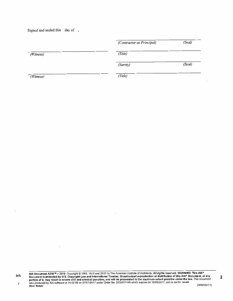
This form shall be considered an integral part of FAC Document 632, Bid Form, and shall be submitted with the Bid Form. The term Subcontractor as used herein shall be used as defined in FAC Document 631, Instructions to Bidders. For each “TYPE OF WORK” listed below, list the name of the subcontractor who will be performing any portion of that work. Use additional sheets, if needed. Bidder may list itself to self-perform, as defined in FAC Document 631, Instructions to Bidders, a type of work when the Bidder is currently licensed to and shall perform that type of work and provides completed FAC Document 634, Bidder Project Data for Self-Performed Projects, within five (5) days to the date of this bid, for at least two (2) previously self-performed projects of comparable size and scope of this Contract for the last five (5) years. There shall be no exceptions to a Bidder’s obligation to provide the aforementioned documentation in the time frame provided. Failure to provide any of the aforementioned documentation or comply with the requirements of this form shall constitute a material deviation from the requirements of this Solicitation and shall serve as grounds for rejecting the bid as non-responsive. (Consultant: modify the list of work in the table below as needed for the Project.)
TYPE OF WORK SUBCONTRACTOR
1. Chiller Manufacturer
2. Hydronic Piping
3. Insulation
4. Electrical
5. General Construction

BIDDER PROJECT DATA FOR SELF-PERFORMED PORTIONS OF THE WORK
SCHOOL BOARD OF VOLUSIA COUNTY FLORIDA FAC DOCUMENT 634
Form Rev: 2019-July-01 FAC Document 634 – Bidder Project Data for Self-Performed Portions of the Work Page 1 of 2
Facility Name: Deltona Lakes Elementary
Project Name: Upgrade Chiller Plant
VCS Project No.: 2047712
Instructions to Bidder: Work completed in the past 5-years. For each type of work proposed to be self-performed by Bidder in FAC Document 633 of the Solicitation, provide full responses to this form. In the event Bidder requires additional space, Bidder is authorized to reproduce this form.
Submitted by - Firm Name:
Firm Address:
Self-performed Project No. 1
Project:
A. Type of Work:
Description: Date Completed:
Location:
Value of Self-performed Work: Total Project Value:
B. Owner:
Contact Person(s): Phone:
Email:
Office Address:
C. Arch. or Eng.:
Contact Person(s): Phone:
Email:
Office Address:
Self-performed Project No. 2
Project:
A. Type of Work:
Description: Date Completed:
Location:
Value of Self-performed Work: Total Project Value:
B. Owner:
Contact Person(s): Phone:
Email:
Office Address:
C. Arch. or Eng.:
Contact Person(s): Phone:
Email:
Office Address:

Form Rev: 2019-July-01 FAC Document 634 – Bidder Project Data for Self-Performed Portions of the Work Page 2 of 2
Self-performed Project No. 3
Project:
A. Type of Work:
Description: Date Completed:
Location:
Value of Self-performed Work: Total Project Value:
B. Owner:
Contact Person(s): Phone:
Email:
Office Address:
C. Arch. or Eng.:
Contact Person(s): Phone:
Email:
Office Address:
Self-performed Project No. 4
Project:
A. Type of Work:
Description: Date Completed:
Location:
Value of Self-performed Work: Total Project Value:
B. Owner:
Contact Person(s): Phone:
Email:
Office Address:
C. Arch. or Eng.:
Contact Person(s): Phone:
Email:
Office Address:
The foregoing is a statement of fact. Any inaccurate information disclosed in this form shall constitute a major deviation from the Solicitation and result in the rejection of bid as non-responsive to the requirements of the Solicitation.
Print Name Title
Signature Date

TRENCH SAFETY ACT FORM
SCHOOL BOARD OF VOLUSIA COUNTY FLORIDA FAC DOCUMENT 635
Form Rev: 2019-July-01 FAC Document 635 – Trench Safety Act Form - Page 1 of 1
Facility Name: Deltona Lakes Elementary
Project Name: Upgrade Chiller Plant
VCS Project No.: 2047712 This form shall be completed, signed and submitted with FAC Document 632, Bid Form. Failure to submit this form at the time of bid will constitute automatic disqualification and non-acceptance of bid proposal. The undersigned, herein called "Bidder", has determined to his own complete satisfaction that all portions of the Florida Trench Safety Act (90-96, Laws of Florida) as the OSHA Excavation Safety Standards 29, CFR part 1926.650 Subpart P, will be fully complied with and executed properly on this project. Bidder acknowledges that included in the various items of the proposal and in the Total Bid Price are costs for complying with the Florida Trench Safety Act (90-96, Laws of Florida) effective October 1, 1990. The bidder further identifies the costs to be summarized below:
Trench Safety Measure
(Description)
Units of Measure (LF, SY)
Unit (Quantity)
Unit Cost
Extended Cost
A.
B.
C.
D.
Total
In Witness whereof, the Bidder as hereunto set his signature and affixed his seal
this day of in the year
Firm: (SEAL)
By:
Name and Title:

BID PROTEST BOND
SCHOOL BOARD OF VOLUSIA COUNTY FLORIDA FAC DOCUMENT 636
Form Rev: 2019-July-01 FAC Document 636 – Bid Protest Bond - Page 1 of 2
Bond Number:
Facility Name:
Project Name:
VCS Project No.: KNOW ALL PERSONS BY THESE PRESENTS:
That we, a (select one) corporation joint venture partnership proprietorship
limited liability company organized and existing under the laws of the State of , and duly authorized
to do business in the State of Florida and having its principal place of business at as PRINCIPAL;
and , a surety company, organized under the laws of the State of , and duly authorized to
do business in the State of Florida, whose principal place of business is as SURETY, are held and
firmly bound unto the School Board of Volusia County Florida as OBLIGEE in the amount of
Dollars ($ ) for the payment of which sum we bind ourselves, our heirs, personal representatives,
successors and assigns, jointly and severally.
THIS BOND is issued under provisions of Section 255.0516, Florida Statutes. The above-named
principal has initiated an administrative protest pursuant to Section 120.57, Florida Statutes, regarding the
School Board of Volusia County’s (Board) bid solicitation, bid rejection or contract award for the above-
referenced project, which protest is conditioned upon the posting of a bond. The bond shall be conditioned
upon the payment of all costs and attorneys’ fees which may be adjudged against the person filing the
protest in the administrative hearing in which the action is brought and any subsequent appellate court
proceeding.
NOW, THEREFORE, if the Principal, after conclusion or termination of the administrative hearing
process, and/or any appellate court proceedings regarding the protest, shall satisfy all attorneys’ fees,
costs and interest thereon, rendered by final order and/or judgment, in favor of the Board as the prevailing
party, then the obligation shall be null and void; otherwise this bond shall remain in full force and effect.
The Board may bring an action in a proper court on this bond for the amount of such liability,
including all additional costs and attorneys’ fees associated with a claim against the bond.

Form Rev: 2019-July-01 FAC Document 636 – Bid Protest Bond - Page 2 of 2
PRINCIPAL
BY
TITLE (CORPORATE SEAL)
ATTEST
TITLE
SURETY
BY (CORPORATE SEAL)
TITLE
Florida Licensed Insurance Agent
NOTE: Power of attorney showing authority of Surety’s agent or Attorney in fact must be attached.


PERFORMANCE AND PAYMENT BOND
SCHOOL BOARD OF VOLUSIA COUNTY FLORIDA FAC DOCUMENT 640
Form Rev: 2019-July-01 FAC Document 640 – Performance and Payment Bond - Page 1 of 2
PUBLIC CONSTRUCTION BOND
Bond No.
BY THIS BOND, WE (Contractor Firm) , (Physical Address) , (Phone) , a corporation,
(Surety Firm) , (Physical Address) , (Phone) , as Surety, are bound to (Owner) School Board of
Volusia County Florida, (Address) 200 North Clara Avenue, DeLand Florida 32720, (Phone) (386) 734-7190,
herein called Owner, in the sum of ($ ) for payment of which we bind ourselves, our heirs,
personal representatives, successors, and assigns, jointly and severally.
THE CONDITION OF THIS BOND is that if Principal:
1. Performs the contract dated , between Principal and Owner for construction of (Facility
Name) , (Address) , (Project Name) ,(Contract/Project No.) , the contract being made
a part of this bond by reference, at the times and in the manner prescribed in the contract; and
2. Promptly makes payments to all claimants, as defined in Section 255.05(1), Florida Statutes,
supplying Principal with labor, materials, or supplies, used directly or indirectly by Principal, in the
prosecution of the work provided for in the contract; and
3. Pays Owner all losses, damages, expenses, costs, and attorney’s fees, including appellate
proceedings, that Owner sustains because of a default by Principal under the contract; and
4. Performs the guarantee of all work and materials furnished under the contract for the time
specified in the contract, then this bond is void; otherwise it remains in full force.
Any action instituted by a claimant under this bond for payment must be in accordance with the
notice and time limitation provisions in Section 255.05(2), Florida Statutes.
Any changes in or under the contract documents and compliance or noncompliance with any
formalities connected with the contract or the changes does not affect Surety’s obligation under this
bond.

Form Rev: 2019-July-01 FAC Document 640 – Performance and Payment Bond - Page 2 of 2
DATED ON day of ,
Signed, sealed and delivered in the presence of:
By:
As to President / Principal President / Principal
(Print/Type Name of Witness to Contractor) (Print/Type Name of Contractor)
By:
Attorney-in-Fact
As to Surety (Print/Type Name of Attorney-in-Fact)
(Print/Type Name of Witness to Surety) Florida Resident Agent
(Print/Type Name of Florida Resident Agent)
NOTE: If both Principal and Surety are corporations, the respective corporate seals should be affixed and attached. Power-of- Attorney to be attached.
APPROVED
Approved as to form only and for reliance only by the School Board of Volusia County.
Signature
Printed Name
Florida Bar Number

CONTRACTOR’S DIRECT MATERIAL PURCHASE AFFIDAVIT SCHOOL BOARD OF VOLUSIA COUNTY FLORIDA
FAC DOCUMENT 641
Form Rev: 2019-July-01 FAC Document 641 – Contractor’s Direct Material Purchase Affidavit - Page 1 of 1
STATE OF FLORIDA COUNTY OF VOLUSIA COMES NOW , and after being duly sworn, does depose and state as follows:
1. My name is: , I am employed in the position of (title) for (Contractor) .
2. I am over the age of eighteen years and I have personal knowledge of the facts stated herein.
3. All of the materials which the School Board of Volusia County Florida has purchased directly for the project known as (Facility Name) , (Project Name) , (VCS Project No.) , and pursuant to AIA Document A201-2017, Article 3.4.5 have been purchased from subcontractors, suppliers or vendors who provided bids to the Contractor for this Project and whose bids were relied upon by the Contractor in submitting its bid to Volusia County Schools.
4. All materials purchased directly by Volusia County Schools from the Contractor's subcontractors,
suppliers and vendors were purchased at or below the price originally negotiated by the Contractor.
FURTHER AFFIANT SAYETH NAUGHT
Sworn to and subscribed before me this day of .
Signature of Notary Public, State of Florida Print, Type or Stamp Commissioned Name of Notary Public
Personally Known or Produced Identification
Type of I. D. Produced

CONTRACTOR’S ACKNOWLEDGMENT FORM
SCHOOL BOARD OF VOLUSIA COUNTY FLORIDA FAC DOCUMENT 642
(Asbestos Survey)
Form Rev: 2019-July-01 FAC Document 642 – Contractor’s Acknowledgement Form - Page 1 of 1
TO: Volusia County Schools Facilities Design and Construction 3750 Olson Drive Daytona Beach, Florida 32124 I acknowledge that I have been given access to and have read the Asbestos Survey, Management Plan, Re-inspection Report (if applicable) and/or Certificate of Final Inspection (if applicable). Facility Name:
Address:
Not applicable - Reason:
I further acknowledge that I must cease work and notify the project manager and environmental specialist, 3750 Olson Drive, Daytona Beach Florida 32124, telephone number (386) 947-8786, in the event of encountering materials not previously identified by the aforementioned reports. In addition, I understand that any questions regarding the aforementioned reports should be directed to the environmental specialist as stated above. My reason for being in the school is: My signature is acknowledgement of the above.
Date:
(Signature)
Printed Name:
Firm’s Name:
Address:
Telephone:

NOTICE TO PROCEED
SCHOOL BOARD OF VOLUSIA COUNTY FLORIDA FAC DOCUMENT 650
Form Rev: 2019-July-01 FAC Document 650 – Notice to Proceed - Page 1 of 1
DATE:
TO:
FROM:
FACILITY NAME: PROJECT NAME: PROJECT NO.:
NOTICE TO PROCEED
In accordance with the Agreement dated , , between the School Board of Volusia County
and your company, you are hereby notified to commence work on or before , and you are to
complete the work within ( ) consecutive calendar days thereafter. The date of substantial
completion for all work is , .
ACCEPTANCE OF NOTICE
Receipt of the above written NOTICE TO PROCEED is hereby acknowledged by:
Firm Name:
this day of ,
By
Name / Title
INSTRUCTIONS
Architect / Engineer:
1. Complete top section of document; produce four (4) original documents 2. Transmit all four (4) original documents to Contractor 3. Upon receipt of three (3) executed documents from the Contractor; keep one (1) for your
records; return remaining two (2) to the VCS Project Manager Contractor:
1. Complete Acceptance of Notice section; sign all four (4) original documents 2. Keep one (1) original document; return the remaining three (3) to the Architect / Engineer at the
address shown above.


ARCHITECT’S FIELD REPORT SCHOOL BOARD OF VOLUSIA COUNTY FLORIDA
FAC DOCUMENT 651
Form Rev: 2019-July-01 FAC Document 651 – Architect’s Field Report - Page 1 of 1
FACILITY NAME: FIELD REPORT NO: OWNER
ARCHITECT
PROJECT NAME: DATE OF ISSUANCE: CONTRACTOR
OTHER
VCS PROJECT NO:
TO CONTRACTOR: FROM ARCHITECT: ARCHITECT’S
PROJECT NO:
DATE: TIME: WEATHER: TEMP. RANGE:
EST. % OF COMPLETION: CONFORMANCE WITH SCHEDULE (+, -)
WORK IN PROGRESS: PRESENT AT SITE:
OBSERVATIONS:
ITEMS TO VERIFY:
INFORMATION OR ACTION REQUIRED:
ATTACHMENTS:
REPORTED BY:
(Signature) (Printed name and title)

ARCHITECT’S SUPPLEMENTAL INSTRUCTIONS SCHOOL BOARD OF VOLUSIA COUNTY FLORIDA
FAC DOCUMENT 652
Form Rev: 2019-July-01 FAC Document 652 – Architect’s Supplemental Instructions - Page 1 of 1
FACILITY NAME: INSTRUCTIONS NO: OWNER
ARCHITECT
PROJECT NAME: DATE OF ISSUANCE: CONTRACTOR
OTHER
VCS PROJECT NO:
TO CONTRACTOR: FROM ARCHITECT: ARCHITECT’S
PROJECT NO:
The Work shall be carried out in accordance with the following supplemental instructions issued in accordance with the Contract Documents without change in Contract Sum or Contract Time. Proceeding with the Work in accordance with these instructions indicates your acknowledgement that there will be no change in the Contract Sum or Contract Time.
Description: (Insert a written description of the supplemental instructions.)
Attachments: (List attached documents that support description.)
ISSUED BY: ACCEPTED BY:
Architect (signature) Contractor (signature) Date

PROPOSAL REQUEST SCHOOL BOARD OF VOLUSIA COUNTY FLORIDA
FAC DOCUMENT 653
Form Rev: 2019-July-01 FAC Document 653 – Proposal Request - Page 1 of 1
FACILITY NAME: PROPOSAL REQUEST NO: OWNER
ARCHITECT
PROJECT NAME: DATE OF ISSUANCE: CONTRACTOR
OTHER
VCS PROJECT NO:
TO CONTRACTOR: FROM ARCHITECT: ARCHITECT’S
PROJECT NO:
Please submit an itemized proposal for changes in the Contract Sum and Contract Time for proposed modifications to the Contract Documents described herein.
THIS IS NOT A CHANGE ORDER, A CONSTRUCTION CHANGE DIRECTIVE OR A DIRECTION TO PROCEED WITH THE WORK DESCRIBED IN THE PROPOSED MODIFICATIONS.
Description: (Insert a written description of the Work.)
Attachments: (List attached documents that support description.)
REQUESTED BY:
(Signature) (Printed name and title)

CHANGE ORDER
SCHOOL BOARD OF VOLUSIA COUNTY FLORIDA FAC DOCUMENT 658
Form Rev: 2019-July-01 FAC Document 658 – Change Order - Page 1 of 2
Agreement on and execution of any Change Order shall constitute a final settlement and a full accord and satisfaction of all matters relating to the Change and to the impact of the Change on unchanged Work, including all indirect costs of whatever nature, and all adjustments to the Contractor Schedule.
TRANSMIT COMPLETED DOCUMENT TO: Volusia County Schools Facilities Design and Construction 3750 Olson Drive Daytona Beach, Florida 32124
● The Owner authorized the Contractor to make the following changes(s) in the Contract dated:
● Change Order Number:
School Board of Volusia County Florida School District
Facility Name
Project Name
VCS Project Number
OWNER: School Board of Volusia County Florida
ADDRESS: 200 North Clara Avenue (PO Box 2118) DeLand Florida 32720 (32721-2118)
Street / P.O. Box City State Zip
ARCHITECTURAL FIRM NAME:
ADDRESS:
Street / P.O. Box City State Zip
CONTRACTOR FIRM NAME:
ADDRESS:
Street / P.O. Box City State Zip
● The Contract is changed as follows: (See Page 2 of 2, Additional Information, for detailed explanation.)
● The original Contract Sum: $
● The net change by previously authorized Change Orders: $
● The Contract Sum prior to this Change Order was: $
● The Contract Sum will be increased by this Change Order in the amount of: $
● The new Contract Sum including this Change Order will be: $
● The Contract Time will be increased by days.
● The date of Substantial Completion as of the date of this Change Order therefore is:
ARCHITECT CERTIFICATION: In my considered professional opinion as project architect , the prices quoted in this Change Order are both fair and reasonable and in the proper ratio to the cost of the original work contract under benefit of competitive bidding.
Architect's Name and Title:
Architect's Signature: Date:
ACCEPTED Contractor’s Name and Title:
Contractor’s Signature: Date:
APPROVED Owner’s Signature: Date:
(SUPERINTENDENT OR DESIGNEE FOR THE BOARD)

Form Rev: 2019-July-01 FAC Document 658 – Change Order - Page 2 of 2
Change Order Number:
Facility Name:
Project Name:
VCS Project No.: ADDITIONAL INFORMATION (modify below as needed for this Change Order): Owner Requested Changes
Description Amount Days
$
Total Owner Requested Changes $
Unforeseen Conditions
Description Amount Days
$
Total Unforeseen Conditions $
Design Changes
Description Amount Days
$
Total Design Changes $
Building Code Requirements
Description Amount Days
$
Total Building Code Requirements $
Total
Amount Days
Total Change Order $


CERTIFICATE OF SUBSTANTIAL COMPLETION SCHOOL BOARD OF VOLUSIA COUNTY FLORIDA
FAC DOCUMENT 660
Form Rev: 2019-July-01 FAC Document 660 - Certificate of Substantial Completion - Page 1 of 1
OWNER: FACILITY NAME:
School Board of Volusia County Florida
200 North Clara Avenue ADDRESS:
DeLand, Florida 32720
Mailing address: CITY, STATE ZIP:
3750 Olson Drive, Daytona Beach Florida 32124
PROJECT NAME:
CONTRACTOR:
VCS PROJECT NO:
AGREEMENT DATE:
PROJECT OR DESIGNATED PORTIONS SHALL INCLUDE:
The entire project as contracted. The Work performed under this Contract has been reviewed and found, to the Architect’s best knowledge, information and belief, to be substantially complete. Substantial Completion is the stage in the progress of the Work when the Work or designated portion thereof is sufficiently complete in accordance with the Contract Documents so the Owner can occupy or utilize the Work for its intended use. The date of Substantial Completion of the Project or portion thereof designated above is hereby established as which is also the date of commencement of applicable warranties required by the Contract Documents, except as stated below.
A list of items to be completed or corrected (Punch List) is attached hereto. The failure to include any items on such list does not alter the responsibility of the Contractor to complete all Work in accordance with the Contract Documents.
ARCHITECTURAL FIRM (Type or print signatory name)
Signature Date
The Contractor will complete or correct the Work on the list of items (Punch List) attached hereto within days from the above date of substantial completion.
CONTRACTOR FIRM (Type or print signatory name)
Signature Date The Owner accepts the Work or designated portion thereof as substantially complete and will assume full possession thereof at: (time) on (date).
School Board of Volusia County Florida
OWNER Superintendent or designee (Signature) Date The Owner assumes responsibilities for security and utilities on the date of substantial completion as established above.

CONTRACTOR AFFIDAVIT
SCHOOL BOARD OF VOLUSIA COUNTY FLORIDA FAC DOCUMENT 661
Form Rev: 2019-July-01 FAC Document 661 – Contractor Affidavit - Page 1 of 1
PURSUANT TO SECTION 713.06(3), FLORIDA STATUTES TO: SCHOOL BOARD OF VOLUSIA COUNTY FLORIDA The undersigned, as Contractor, has heretofore, on the day of , in the year , been awarded a contract by you, as Owner, to furnish all of the materials and labor in the construction project entitled (Facility Name) , (Address) , (Project Name) ,(VCS Project No.) , for the final contract price of ($ ) in accordance with plans and specifications therefore, as prepared by , Architect. The said project has been completed and the contract and plans therefore fully complied with, and all of the contract price has been paid by you, except the final payment thereon, which is now due, but is being withheld until a sworn statement is furnished as required by law, showing whether there are any unpaid and outstanding bills in connection with said building. That the undersigned hereby certified, under oath, that all lienors contracting directly with or directly employed by the undersigned, on said contract, have been paid in full, and further certified, under oath, that there are no outstanding or unpaid bills for labor performed or materials furnished in connections with said work or improvements. That this sworn statement is furnished by the Contractor to the Owner pursuant to Section 713.06(3), Florida Statutes.
IN WITNESS WHEREOF, the undersigned has hereunto set his hand and seal this day of ,
Witnessed by:
(SEAL)
(Witness Signature) (Contractor Signature)
(Print or Type Name, Title) (Print or Type Name, Title)
STATE OF FLORIDA, COUNTY OF VOLUSIA
Before me, the undersigned authority, personally appeared
to me well-known and known to me to be the person described in and who executed the foregoing instrument, and he acknowledged before me that he executed the same. IN WITNESS WHEREOF, I have hereunto set my hand and official seal this
day of ,
(Notary Seal)
My commission expires: Notary Public, State of Florida
(Date) (Print, type or stamp name of notary public)
Personally known to me Produced ID (Type of ID, if applicable)

RECEIPT AND RELEASE
SCHOOL BOARD OF VOLUSIA COUNTY FLORIDA FAC DOCUMENT 662
Form Rev: 2019-July-01 FAC Document 662 – Receipt and Release - Page 1 of 1
KNOW ALL MEN BY THESE PRESENTS: That the undersigned , of was heretofore on day of , awarded a contract by the SCHOOL BOARD OF VOLUSIA COUNTY FLORIDA, for the final contract price of , ($ ) to furnish all of the materials and labor in the construction project entitled (Facility Name) , (Address) , (Project Name) , (VCS Project No.) , , in accordance with the plans and specifications therefore, as prepared by , Engineer, and the undersigned has completed said work and fully complied with said contract and has heretofore received the sum of , ($ ) as payment thereon. That the undersigned has this date received from the SCHOOL BOARD OF VOLUSIA COUNTY FLORIDA, the sum of , ($ ) representing the full balance due him as Contractor, under terms of said contract, and certifies that said contract has been fully performed in accordance with terms thereof and that he, as Contractor, has received all monies due and to become due to him thereunder for work performed and materials furnished in connection with said work, and that he has paid in full all persons furnishing labor and/or materials in connection therewith, including all subcontractors and suppliers, and that there are no unpaid bills for labor performed or materials furnished in connection with said work or improvements. That the undersigned, for value received, does hereby forever release and discharge the said building and premises as described in said contract, from any and all liens, claims or demands whatsoever that he has or may have for work performed or materials furnished in connection therewith, or for work performed or materials furnished thereon by any subcontractor or supplier, and that he will hold the SCHOOL BOARD OF VOLUSIA COUNTY FLORIDA, safe and harmless from any and all loss and liability arising or to arise by reason of any unpaid bills for labor performed or materials furnished on said building or premises in connection with said work or improvements.
IN WITNESS WHEREOF, the undersigned has hereunto set his hand and seal this day of ,
Witnessed by:
(SEAL)
(Witness Signature) (Contractor Signature)
(Print or Type Name, Title) (Print or Type Name, Title)
STATE OF FLORIDA, COUNTY OF VOLUSIA
Before me, the undersigned authority, personally appeared
to me well-known and known to me to be the person described in and who executed the foregoing instrument, and he acknowledged before me that he executed the same. IN WITNESS WHEREOF, I have hereunto set my hand and official seal this
day of ,
(Notary Seal)
My commission expires: Notary Public, State of Florida
(Date) (Print, type or stamp name of notary public)
Personally known to me Produced ID (Type of ID, if applicable)
Deltona Lakes Elementary Upgrade Chiller Plant, Project No. 2047712 1/6/2020
Execution Requirements Section 01 73 03
Page 1 of 15
SECTION 01 73 03
EXECUTION REQUIREMENTS
PART 1 GENERAL
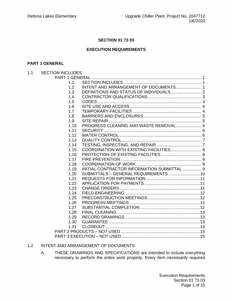
1.1 SECTION INCLUDES PART 1 GENERAL ............................................................................................. 1
1.1 SECTION INCLUDES .................................................................. 1 1.2 INTENT AND ARRANGEMENT OF DOCUMENTS ..................... 1 1.3 DEFINITIONS AND STATUS OF INDIVIDUALS .......................... 2 1.4 CONTRACTOR QUALIFICATIONS ............................................. 3 1.5 CODES ........................................................................................ 3 1.6 SITE USE AND ACCESS ............................................................ 4 1.7 TEMPORARY FACILITIES .......................................................... 4 1.8 BARRIERS AND ENCLOSURES ................................................. 5 1.9 SITE REPAIR .............................................................................. 5 1.10 PROGRESS CLEANING AND WASTE REMOVAL ..................... 6 1.11 SECURITY .................................................................................. 6 1.12 WATER CONTROL ..................................................................... 6 1.13 QUALITY CONTROL ................................................................... 7 1.14 TESTING, INSPECTING, AND REPAIR ...................................... 7 1.15 COORDINATION WITH EXISTING FACILITIES .......................... 8 1.16 PROTECTION OF EXISTING FACILITIES .................................. 8 1.17 FIRE PREVENTION .................................................................... 9 1.18 COORDINATION OF WORK ....................................................... 9 1.19 INITIAL CONTRACTOR INFORMATION SUBMITTAL ................ 9 1.20 SUBMITTALS – GENERAL REQUIREMENTS ...........................10 1.21 REQUESTS FOR INFORMATION ..............................................11 1.22 APPLICATION FOR PAYMENTS ...............................................11 1.23 CHANGE ORDERS ....................................................................11 1.24 FIELD ENGINEERING ................................................................12 1.25 PRECONSTRUCTION MEETINGS ............................................12 1.26 PROGRESS MEETINGS ............................................................12 1.27 SUBSTANTIAL COMPLETION ...................................................12 1.28 FINAL CLEANING ......................................................................13 1.29 RECORD DRAWINGS ................................................................13 1.30 GUARANTEE .............................................................................13 1.31 CLOSEOUT ................................................................................14
PART 2 PRODUCTS – NOT USED ...................................................................15 PART 3 EXECUTION – NOT USED ..................................................................15
1.2 INTENT AND ARRANGEMENT OF DOCUMENTS
A. THESE DRAWINGS AND SPECIFICATIONS are intended to include everything necessary to perform the entire work properly. Every item necessarily required

Deltona Lakes Elementary Upgrade Chiller Plant, Project No. 2047712 1/6/2020
Execution Requirements Section 01 73 03
Page 2 of 15
may not be specifically mentioned or shown. Unless expressly stated, all systems and equipment shall be complete and operable.
B. TITLES AND HEADINGS to Divisions, Sections and paragraphs in these Subcontract documents are introduced for convenience and shall not be taken as a correct or complete segregation of the several units of materials and labor.
C. THE TERMS of the Agreement, General Provision for Fixed Price Construction and General Requirements apply to each Division of these Specifications as fully as if repeated within that Division.
D. ITEMS LISTED under Scope of Work for each Division of the Specifications are not necessarily all inclusive. The Contractor shall be responsible for the complete job.
E. PORTIONS OF THESE Specifications are of the abbreviated, simplified type and may include incomplete sentences. 1. Omissions of words or phrases such as the Contractor shall, in conformity
with, shall be, as noted on the drawings, in accordance with details, a, the and all, are intentional. Omitted words or phrases shall be supplied by inference in the same manner as they are when a note occurs on the drawings.
2. Such terms as approved, reviewed, equal, as directed, as required, as permitted, acceptable, satisfactory mean by or to the Architect-Engineer or Project Manager.
3. The words “shall be” are included by inference where a colon (:) is used within sentences or phrases.
1.3 DEFINITIONS AND STATUS OF INDIVIDUALS
A. The terms defined in the agreement, general conditions, and general provision for fixed price construction shall apply throughout. Certain additional terms and refinements shall apply as specified below:
B. CONTRACTOR: The term "Contractor" shall mean the person or firm responsible for the execution of this Contract, or any portion thereof. This shall include the General or Prime Contractor, all Contractors and any Sub-Contractors and suppliers. Contractor usually refers to the particular contractor concerned with the Section in which the term is found, but this in no way relieves the Prime Contractor of its sole responsibility for completing the entire work of this Contract.
C. The Contractor shall complete the work in accordance with the Contract Documents, approved submittals that comply with the Contract Documents, and any clarifications or instructions issued by the Architect and/or Engineer. The Contractor shall not be relieved of any responsibility to comply with such requirements by the activities of the Architect-Engineer or the Owner’s Project Manager.
D. ARCHITECT-ENGINEER: The term "Architect-Engineer" is the person or firm designated as the responsible design professional. The Architect-Engineer shall interpret and clarify the intent of the construction Contract Documents, will participate with the Owner in determining the acceptability of workmanship, materials and the progress of the work and entitlement to payment. The Architect-

Deltona Lakes Elementary Upgrade Chiller Plant, Project No. 2047712 1/6/2020
Execution Requirements Section 01 73 03
Page 3 of 15
Engineer will review proposed changes, substitutions, shop drawings and schedules submitted by the Contractor for approval as required by the Contract Documents. The Architect-Engineer shall have access to the work at all times and the authority to recommend that the Owner not accept any work or materials deemed not to conform to the requirements of the Contract. All professional design responsibility matters will be determined by the Architect-Engineer.
E. OWNER PROJECT MANAGER (PROJECT MANAGER): During the Construction Phase, the Owner’s Project Manager will be involved in construction observations and verifying the progress of the construction.
1.4 CONTRACTOR QUALIFICATIONS
A. The Prime contractor shall be well qualified to perform the scope of work and shall have the following experience: 1. Minimum of 5 years in business using the current name. 2. Minimum of 5 years experience performing projects with similar
construction cost, scope and construction schedule. Contractor shall provide a list of projects upon request.
1.5 CODES
A. Applicable provisions of the Constitution and Laws of the State of Florida are hereby referred to and made a part of this Contract and all work performed shall be in accordance with such laws, regulations and the latest edition or supplement or amendment thereto in effect at the time of submittal of bid shall be considered to be the issue in effect (unless shown otherwise) of all applicable codes including, but not limited to: 1. Florida Building Code (FBC) 2. Florida Electrical Code, (FEC) 3. Florida Mechanical Code (FMC) 4. Florida Plumbing Code (FPC) 5. Florida Energy Code (FEC) 6. Florida Fire Code (FFC) 7. NFPA 70 National Electrical Code 8. Americans with Disabilities Act (ADA)
B. Where codes or standard specifications other than those listed in this paragraph are referred to in the different Divisions of these specifications, it is understood that they apply as fully as if cited here.
C. Where differences exist between codes affecting this work, the code affording the greatest protection to the Owner shall govern.
D. If the Contractor observes that these drawings and specifications are at variance with the codes, the Contractor shall notify the Project Manager in writing at once for resolution in writing.
E. Pursuant to OSHA Regulations, the Contractor shall include in its base bid all costs incidental to the provision of adequate sheeting, shoring, bracing or equivalent method for the protection of life or limb, which shall conform to applicable Federal and State safety orders.

Deltona Lakes Elementary Upgrade Chiller Plant, Project No. 2047712 1/6/2020
Execution Requirements Section 01 73 03
Page 4 of 15
F. Maintenance clearances shall be maintained around equipment as required by the Codes and Standards, and as recommended by the equipment manufacturers. The maintenance envelope and equipment access shall be kept clear of any obstruction. It is Contractor’s responsibility to enforce these requirements with all the Contractors. The Contractor and Contractors shall be responsible for correcting any infringement on this requirement at no cost to the Owner.
1.6 SITE USE AND ACCESS
A. SIMULTANEOUS USE OF SITE: The contractor shall coordinate the work with the owner to allow Owner occupancy, work by other contractors, and use of the facility by the public as required by the Owner. Site utility shutdowns must be closely coordinated with the onsite staff with minimum 48 hours notice for shutdowns that may interfere with the Owner’s activities.
B. PARKING: Parking for private vehicles is limited. Parking for Contractors and their workers will be limited to the construction limits and as agreed with the Project Manager.
C. SITE ACCESS: Heavy and slow moving trucking will not be permitted on site during transition periods. Trucks attempting to enter the site during this period shall be denied access.
D. CONSTRUCTION LIMITS: The Contractor shall confine the construction to the immediate area within the construction limits and spaces specifically coordinated for use during construction.
E. WORKING HOURS: Unless otherwise noted, construction operations shall be as follows: 1. Schools – During summer break: The facility is continuously available for
work activities. Utility outages must be coordinated with the onsite staff. Summer school activities shall not be interfered with.
2. Schools – During school year: School activities take priority over construction activities. Construction may occur if it does not interfere with school activities. Construction that may disrupt school activities must occur after school hours or on the weekends.
1.7 TEMPORARY FACILITIES
A. GENERAL: Provide construction facilities and temporary controls necessary for the Work.
B. ELECTRICITY: Owner will pay cost of electricity used. Provide temporary electricity and power outlets for construction operations, connections, branch wiring, distribution boxes, and flexible power cords as required. All temporary services shall comply with NEC. Do not disrupt Owner's need for continuous service.
C. LIGHTING FOR CONSTRUCTION PURPOSES: Provide and maintain temporary lighting for construction operations. Provide branch wiring from power source to distribution boxes with lighting conductors, pigtails, and lamps as required. Permanent building lighting may be utilized during construction. Repair, clean, and replace lamps at end of construction.

Deltona Lakes Elementary Upgrade Chiller Plant, Project No. 2047712 1/6/2020
Execution Requirements Section 01 73 03
Page 5 of 15
D. SANITARY FACILITIES: Provide and maintain required facilities and enclosures. Owner’s facilities may not be used. Maintain in clean and sanitary condition.
E. REMOVAL: Remove the construction facilities and temporary controls when they are no longer required. Restore permanent facilities used for or connected to temporary facilities to their original condition or better.
1.8 BARRIERS AND ENCLOSURES
A. BARRIERS AND FENCING: Provide barriers and/or fencing as required to prevent unauthorized entry to construction areas and to protect existing facilities and adjacent properties from damage. Where fencing is needed, the following requirements apply: 1. Provide temporary fence not less than 6 feet in height above grade. 2. Fabric: Provide #9 gage galvanized steel, or equal gage aluminum, woven
together into 2 inch diamond mesh, with both top and bottom edges having a twisted and non-barbed finish.
3. Posts, Rails, and Connections: Standard galvanized steel products of an approved manufacturer, of the size and types as required and approved. Provide top and bottom rails between all posts secured with bolted connections.
4. Gates: Provide access gates for passage of employees and materials, complete with padlock. Fabricate gates with galvanized steel pipe perimeter covered with same fabric specified for fence.
5. Erection: Set posts 4 feet into the ground and not more than 10 feet apart. Install bottom rail not more than 2 inches above existing grade. Pull fabric taut and wire tightly to posts and rails at not more than 2 feet on center.
B. ENCLOSURES: Provide temporary weather tight closures to exterior openings to permit acceptable working conditions and protection of the Work.
C. BARRICADE PLAN: When required by the Owner, provide a site plan indicating locations for barricades.
1.9 SITE REPAIR
A. DEMOLISHED WORK: Where demolition of existing components occurs, repair resulting holes, blemishes, and deficiencies in the finishes and substrate to match surrounding. Repair shall include patching to match surrounding materials, priming surfaces and topcoat painting with two coats to match. 1. Where painted patches do not closely match existing color, the contractor
shall paint to nearest corner or break point.
B. ENTIRE SITE: All construction areas shall be returned to the same or better condition than prior to construction. The contractor may photograph existing conditions to document existing damage.
C. INTERIORS: Patch and paint walls as required. Clean, repair, and/or replace flooring as required. Repair and/or replace furnishings damaged during construction.
D. EXTERIORS: Pressure wash as required. Repair any damage to sidewalks and driveways. Broken concrete must be replaced ‘cut to cut’, patches are not allowed.

Deltona Lakes Elementary Upgrade Chiller Plant, Project No. 2047712 1/6/2020
Execution Requirements Section 01 73 03
Page 6 of 15
E. LANDSCAPING: Replace damaged landscaping. Sod all grassed areas affected by the work, matching the existing grass type.
1.10 PROGRESS CLEANING AND WASTE REMOVAL
A. Clean up and containerize the rubbish (refuse, debris, waste materials, and removed materials and equipment) resulting from the Work at the end of each work day and leave work areas broom clean, except where more stringent cleaning is specified. Locate containerized rubbish where directed.
B. Remove rubbish from site at least once a week and more often if the rubbish presents a hazard. Properly dispose of rubbish.
C. Burning of rubbish will not be permitted.
1.11 SECURITY
A. Facility Key Regulations: 1. Sign Facility keys out and in on a daily basis unless otherwise directed. 2. Keep keys on person at all times while on the premises. Do not loan or
give keys to other persons. 3. Do not remove keys from the premises without written permission from the
Owner. 4. Report lost, missing, or stolen keys immediately. Assume responsibility for
cost of necessary key and lock replacement as a result of lost, missing, or stolen keys.
B. Identification Badge: Provide and require workers to carry and plainly display at all times identification badges indicating their name and employer.
C. Promptly relock doors and security screens located in access routes, storage areas, and work areas after use.
D. Restore, by the end of each work day, existing in place safety/security items such as doors, screens, alarm systems components, that required removal, replacement, or adjustment to perform the Work, unless otherwise authorized in writing by the Owner.
E. Remove all tools and materials from Owner occupied work areas when the work areas are not attended by employees and at the end of each work day. Store tools in a locked tool box, cabinet, or shed. Store materials in a secure location.
F. Provide security and facilities to protect Work and existing facilities, and Owner's operations from unauthorized entry, vandalism, or theft.
1.12 WATER CONTROL
A. Provide and maintain pumping equipment necessary to keep the work areas free from water. Discharge water into existing storm drainage systems or otherwise disperse as directed.

Deltona Lakes Elementary Upgrade Chiller Plant, Project No. 2047712 1/6/2020
Execution Requirements Section 01 73 03
Page 7 of 15
1.13 QUALITY CONTROL
A. The Contractor shall be fully responsible for inspecting the work of its suppliers, and Subcontractors to assure that the work complies with the standards for materials and workmanship required by the Contract Documents. Inspections, periodic observations and testing performed by the Owner or the Architect-Engineer are for the Owner's benefit and information only and shall not be construed as partial or incremental acceptance of the work and shall not be deemed to establish any duty to the Contractor, its Subcontractors or suppliers.
B. The Subcontractor shall 1. Monitor quality control over Subcontractors, suppliers, manufacturers,
products, services, site conditions, and workmanship, to produce work of the quality specified in the Subcontract documents.
2. Comply fully with manufacturer's instructions, including each step in sequence.
3. Request clarification from Architect-Engineer before proceeding with work when manufacturers' instructions or reference standards conflict with Contract Documents.
4. Comply with specified standards as a minimum quality for the work except when more stringent tolerances, codes, or manufactures instructions require more precise workmanship.
5. Ensure that work is performed by persons specializing in the specific trade and class of work required, and qualified to produce workmanship of specified quality.
6. Secure products in place with positive anchorage devices designed and sized to withstand static and dynamic loading, vibration, physical distortion or disfigurement.
1.14 TESTING, INSPECTING, AND REPAIR
A. The work will be inspected by Owner’s inspectors and/or independent service personnel under coordination of the Project Manager.
B. All work is subject to inspection and shall remain accessible and exposed until it has been inspected. Any work covered up or made inaccessible before such inspection shall be uncovered and made accessible without additional expense to the Owner.
C. Work performed by the Owner, independent service companies, or the Architect-Engineer or any of their employees or consultants shall not (1) relieve the Contractor from responsibility for performing his own quality control and for complying with the requirements of the Contract Documents and (2) shall not create a duty or responsibility of the Owner or Architect/ Engineer to the Contractor, any tier of Subcontractors, material and equipment suppliers, their agents, employees or other persons performing portions of the work.
D. The Owner or the Architect-Engineer will not be responsible for the Contractor's failure to carry out work in accordance with the Contract Documents.

Deltona Lakes Elementary Upgrade Chiller Plant, Project No. 2047712 1/6/2020
Execution Requirements Section 01 73 03
Page 8 of 15
1.15 COORDINATION WITH EXISTING FACILITIES
A. The Engineer has endeavored to coordinate the work with the existing facilities. However, the exact location of existing items may differ from what is shown on the drawings. The Contractor shall apply the design intent to the facility regardless of differences in actual field conditions.
B. Prior to any shutdowns or disconnecting, the contractor shall field verify the service to be modified (piping, hydronic, electrical, ductwork, etc) is correct based upon the design intent.
1.16 PROTECTION OF EXISTING FACILITIES
A. Protect installed Work and existing construction and finishes during performance of the Work.
B. Maintain the building in a watertight condition during performance of the Work.
C. Provide temporary and removable protection for installed products. Control activity in immediate work area to prevent damage.
D. Provide protective coverings at wall projections, jambs, sills, and soffits of openings.
E. Protect finished floors, stairs, and other surfaces from traffic, dirt, wear, damage, and movement of heavy objects. The minimum protection shall be: 1. Cover the entire floor of all spaces affected by the work with Masonite (or
similar product) with taped edges. 2. Furnishings remaining in space: Visqueen covering. Tape edges to prevent
dust. 3. Bookcases: Cover completely with Visqueen and tape edges. 4. Remaining items shall be protected as determined by the contractor. 5. Any items with construction dirt/dust/debris shall be thoroughly cleaned.
F. All protective systems shall be removed and disposed of at the end of the project.
G. Protect smoke detectors from airborne dust and debris. 1. At the beginning of each work day, provide protective coverings over
smoke detectors in areas where airborne dust and debris will be generated by the Work.
2. At the end of the work day, clean the areas in which the smoke detectors are located by whatever means necessary to assure that airborne dust and debris will not contaminate the smoke detectors, then remove protective coverings.
3. Provide signs, instructions and alternate methods for reporting a fire during the periods that the smoke detectors are covered.
H. Prohibit traffic or storage upon waterproofed and roofed surfaces. If traffic or activity is necessary, obtain recommendations for protection from waterproofing or roofing material manufacturer.
I. Protect existing trees and plants during performance of the Work unless otherwise indicated. Box trees and plants within the grading limit lines. Do not deposit
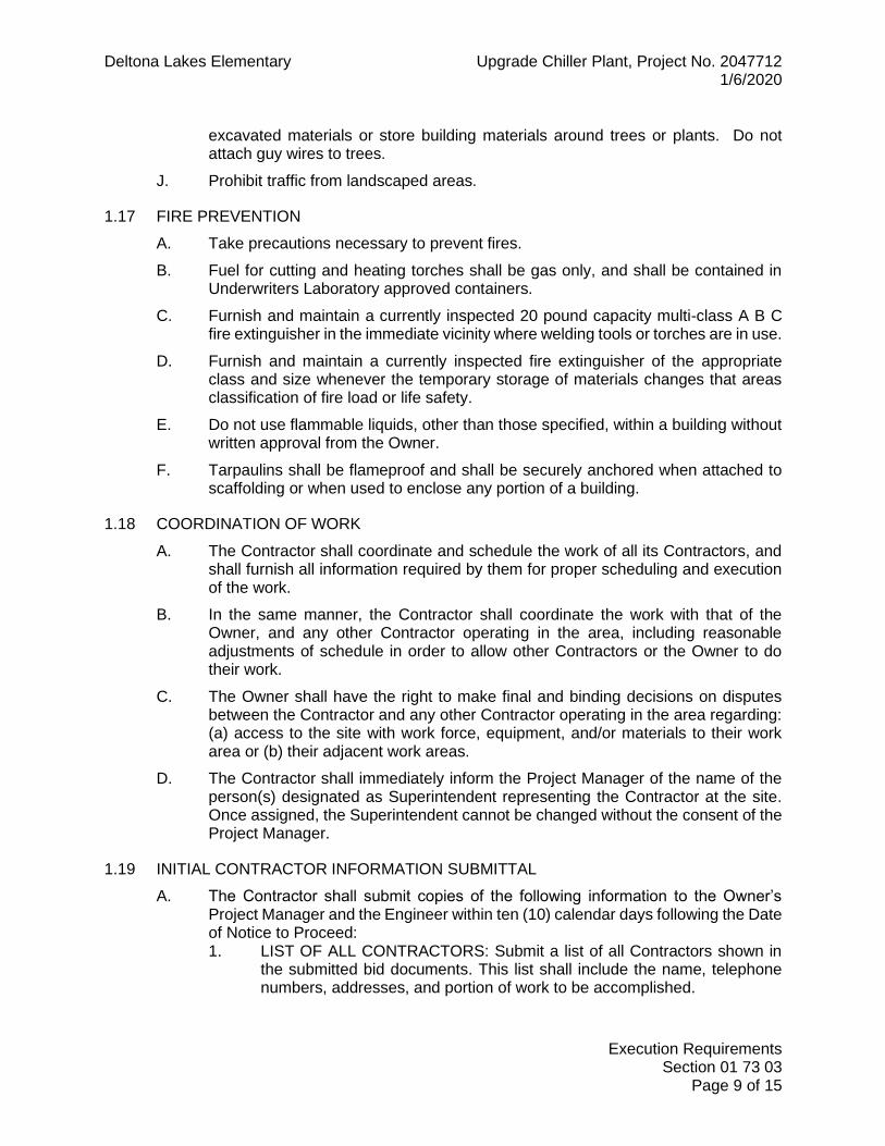
Deltona Lakes Elementary Upgrade Chiller Plant, Project No. 2047712 1/6/2020
Execution Requirements Section 01 73 03
Page 9 of 15
excavated materials or store building materials around trees or plants. Do not attach guy wires to trees.
J. Prohibit traffic from landscaped areas.
1.17 FIRE PREVENTION
A. Take precautions necessary to prevent fires.
B. Fuel for cutting and heating torches shall be gas only, and shall be contained in Underwriters Laboratory approved containers.
C. Furnish and maintain a currently inspected 20 pound capacity multi-class A B C fire extinguisher in the immediate vicinity where welding tools or torches are in use.
D. Furnish and maintain a currently inspected fire extinguisher of the appropriate class and size whenever the temporary storage of materials changes that areas classification of fire load or life safety.
E. Do not use flammable liquids, other than those specified, within a building without written approval from the Owner.
F. Tarpaulins shall be flameproof and shall be securely anchored when attached to scaffolding or when used to enclose any portion of a building.
1.18 COORDINATION OF WORK
A. The Contractor shall coordinate and schedule the work of all its Contractors, and shall furnish all information required by them for proper scheduling and execution of the work.
B. In the same manner, the Contractor shall coordinate the work with that of the Owner, and any other Contractor operating in the area, including reasonable adjustments of schedule in order to allow other Contractors or the Owner to do their work.
C. The Owner shall have the right to make final and binding decisions on disputes between the Contractor and any other Contractor operating in the area regarding: (a) access to the site with work force, equipment, and/or materials to their work area or (b) their adjacent work areas.
D. The Contractor shall immediately inform the Project Manager of the name of the person(s) designated as Superintendent representing the Contractor at the site. Once assigned, the Superintendent cannot be changed without the consent of the Project Manager.
1.19 INITIAL CONTRACTOR INFORMATION SUBMITTAL
A. The Contractor shall submit copies of the following information to the Owner’s Project Manager and the Engineer within ten (10) calendar days following the Date of Notice to Proceed: 1. LIST OF ALL CONTRACTORS: Submit a list of all Contractors shown in
the submitted bid documents. This list shall include the name, telephone numbers, addresses, and portion of work to be accomplished.

Deltona Lakes Elementary Upgrade Chiller Plant, Project No. 2047712 1/6/2020
Execution Requirements Section 01 73 03
Page 10 of 15
2. SCHEDULE OF VALUES: Submit a segregation of the Subcontract price on AIA Form G703 itemizing the estimated cost of each class of work. Each item shall include a pro rata allowance for profit and overhead expense. Insurance and bond expense shall not be prorated but should be shown as separate items. The total of the items shall equal the Contract price. This segregation, when accepted by the Architect-Engineer and Owner’s Project Manager, shall become the basis for determining progress payments.
3. CONSTRUCTION SCHEDULE: Three (3) copies of the construction schedule indicating completion within the time provided by the Contract. The schedule shall be a bar graph or an arrow diagram showing the times the Contractor intends to commence and complete the various work stages. After the initial submittal, the Contractor shall update the schedule monthly by entering actual progress for the period and submit one copy as part of the monthly progress payment request.
1.20 SUBMITTALS – GENERAL REQUIREMENTS
A. Shop drawings and submittal data consisting of brochures, catalogs, material lists, samples, and letters requesting review of materials or substitutions by the Contractor shall be submitted for review where required by the individual specification sections. Specific submittal requirements for each division are provided in each division’s general requirements.
B. When required by the technical specifications, the Contractor shall submit shop drawings, erection drawings, and equipment layouts, and vendor data for review by the Architect-Engineer.
C. The Contractor shall be responsible for and shall check the correctness of all documents including those of Subcontractors prior to submitting them for review.
D. Product Data consisting of brochures, catalogs, material lists, letters, manufacturer’s installation instructions, etc. shall be submitted as described in the specific Sections of the technical specifications. Items for use on this project shall be clearly indicated. Information which is not pertinent shall be voided.
E. Each submittal shall be provided together with a transmittal letter or form and shall itemize the enclosures and indicate the distribution of the transmittal and the enclosures.
F. Shop drawings and other required submittals will be reviewed with reasonable promptness. No delay will be allowed in the progress of the job attributable to Contractor's failure to make required submittals within a reasonable length of time.
G. The Architect-Engineer's favorable review of shop drawings and other submittals shall not relieve the Contractor of responsibility for deviations from drawings or specifications, unless the Contractor has in writing called the Architect-Engineer's attention to such deviations at the time of submission, and the Architect-Engineer has acknowledged in writing such deviations; nor shall it relieve the Contractor from responsibility for errors of any sort in such drawings.
H. If deviations, discrepancies, or conflicts between shop drawing submittals and the drawings and specifications are discovered either prior to or after the shop drawing

Deltona Lakes Elementary Upgrade Chiller Plant, Project No. 2047712 1/6/2020
Execution Requirements Section 01 73 03
Page 11 of 15
submittals are reviewed by the Architect-Engineer, the drawings and specifications shall control and shall be followed.
I. The Contractor shall furnish prints of the favorably reviewed final shop drawings, erection drawings, equipment layouts and vendor data to Subcontractors and suppliers for the proper coordination of their work. The Contractor shall keep one (1) complete set of the above documents at the job site for the use of the Owner and the Architect-Engineer.
1.21 REQUESTS FOR INFORMATION
A. When, during the course of construction, the contractor deems the scope of work is unclear, he shall promptly submit a written Request For Information (RFI) to the engineer for clarification. The RFI shall contain the following: 1. A statement clearly outlining the issue or discrepancy. 2. A recommendation from the contractor regarding the course of action to
take. 3. A statement as to whether or not the contractor’s recommended course of
action will result in added construction costs. 4. A statement as to whether or not the contractor’s recommended course of
action will result in added construction time.
B. The engineer will process and respond to the RFI as quickly as possible.
1.22 APPLICATION FOR PAYMENTS
A. Submit five (5) signed original copies of each application on AIA Form G702 and G703.
B. Include any owner specific documentation required to be provided with the application for payment. Coordinate with the Owner’s purchasing department.
C. Include the Owner Project number on the applications.
D. Content and Format: Utilize Schedule of Values for listing items in Application for Payment.
1.23 CHANGE ORDERS
A. In connection with change orders under this Contract, not covered by unit price or alternate bids, the Owner will use the following formula for approval unless it determines that such amounts would not be acceptable.
B. Basis for Change Order Costs: All change order requests shall be provided with complete time and materials breakout pricing. Costs that lack reference numbers will be rejected. 1. Cost Allowances:
Subcontractor costs (attach full labor and materials breakdown of work) 10% for “Overhead and Profit” for self performed work. 5% for “Overhead and Profit” for non-self performed work. Additional insurance coverage Added Performance and Payment Bond cost (if applicable to the project) Cost of hourly supervision of non-self performed work (if required).

Deltona Lakes Elementary Upgrade Chiller Plant, Project No. 2047712 1/6/2020
Execution Requirements Section 01 73 03
Page 12 of 15
C. Change Order Requests will only be considered when a properly submitted RFI has been processed regarding the issue.
D. To be considered, properly formatted Change Order Requests must be submitted to the engineer within one week of the RFI response.
E. Stipulated Sum/Price Change Order: Based on Proposal Request and Contractor's fixed price quotation or Contractor's request for Change Order as approved by Architect/Engineer.
F. Change Order Forms: AIA G701.
G. For deletions not covered by unit prices or alternate bids, the Contractor agrees that the Owner shall be credited with the estimated cost of the labor, materials, supplies, transportation, payroll taxes, sales taxes, insurance, bond costs, overhead and profit associated with the deleted work.
1.24 FIELD ENGINEERING
A. Employ experienced instrument technician as required to locate reference datum and protect survey control and reference points.
B. Establish elevations, lines, and levels and certify elevations and locations of the Work conform with Contract Documents.
C. Verify field measurements are as indicated on shop drawings or as instructed by manufacturer.
1.25 PRECONSTRUCTION MEETINGS
A. Owner will schedule preconstruction meeting after Notice to Proceed for affected parties.
B. When required in individual specification section, convene pre-installation meeting at Project site prior to commencing work of section.
1.26 PROGRESS MEETINGS
A. Schedule and administer meetings throughout progress of the Work at maximum weekly intervals.
B. Preside at meetings, record minutes, and distribute copies within two days to those affected by decisions made.
1.27 SUBSTANTIAL COMPLETION
A. The contractor shall be granted substantial completion when the following has occurred: 1. The work has been reviewed by the Engineer and all work has been
acceptably completed and a minor punch list remains. 2. All required inspections have successfully passed, including the building
inspection and health and safety inspection.

Deltona Lakes Elementary Upgrade Chiller Plant, Project No. 2047712 1/6/2020
Execution Requirements Section 01 73 03
Page 13 of 15
1.28 FINAL CLEANING
A. Perform final cleaning prior to joint inspection for physical completion. Leave the premises in a neat, unobstructed condition, the work areas broom clean (except where more thorough cleaning is specified), and everything in perfect repair and adjustment.
B. Clean site; sweep paved areas, rake clean landscaped surfaces.
C. Remove tools, equipment, waste and surplus materials, rubbish, and construction facilities from the premises as soon as possible upon completion of the Work.
1.29 RECORD DRAWINGS
A. Maintain at the site a complete, precise, accurate dimensioned record of actual locations of the work, including concealed and embedded work, size and type of equipment, and every change or deviation from original Subcontract Drawings. Keep this record legible and correct weekly as the job progresses on black or blueline prints. Keep Record Drawings available for inspection at all times. Drawings will be inspected before approval of requests for payment.
1.30 GUARANTEE
A. The date of acceptance for all warranties and guarantees shall be defined as the date of substantial completion. The contractor shall purchase extended manufacturer warranties as required to provide the warranty duration required by individual specification sections.
B. All work shall be guaranteed for one (1) year from the date of acceptance against all defects in material, equipment and workmanship. When required by the specifications, guarantees for specific items shall be for periods longer than one (1) year. All guarantees shall be in the following form on the Contractor's own letterhead.
C. Guarantee form: GUARANTEE FOR __(Owner’s Name)__________________________________________ We hereby guarantee___(Project Name)____________________ which we have constructed at ___(Site)______________________. We agree to repair or replace any or all of our work together with any other adjacent work which may be replaced by so doing, that may prove to be defective in its workmanship or materials within a period of one (1) year from date of acceptance (Substantial Completion) without any expense whatsoever to said Owner excluding ordinary wear and tear and unusual abuse or neglect. Further, the following products have been provided with warrantees exceeding one year: Product Warrantee Period ________________________________ _______________ ________________________________ _______________ ________________________________ _______________ ________________________________ _______________

Deltona Lakes Elementary Upgrade Chiller Plant, Project No. 2047712 1/6/2020
Execution Requirements Section 01 73 03
Page 14 of 15
In the event of our failure to comply with above-mentioned conditions within thirty (30) days after being notified in writing of a warrantee issue, we, collectively or separately, do hereby authorize the Owner to have said defects repaired and made good at our expense, and we will honor and pay the costs and charges therefore upon demand. Signed______________________________ (Contractor)
1.31 CLOSEOUT
A. General: The overall process for closeout documentation shall be as follows: 1. Electronic copies of the closeout documents shall be compiled by the Prime
contractor for each discipline with project scope. The electronic documents shall be copied to the shared SEG Dropbox folder and SEG notified that the documents are ready for review.
2. No paper documents shall be produced until the electronic versions are reviewed and accepted.
3. Refer to the Dropbox folders for additional information regarding the file naming conventions and file organization requirements.
4. Once the electronic documents are accepted, the contractor shall deliver the following to SEG for final review: a. Contractual documents
1) Receipt and Release 2) Contractor Affidavit 3) Consent of Surety 4) Final Pay application
b. Three (3) three-ring binders with sorting tabs with hardcopies of the following information: 1) General Project Information 2) Warranty Information 3) Reports 4) O&M Data
c. One full size set of as-built plans from the single, combined PDF as-built file. The printed set must be an EXACT duplicate of the PDF file content. Printing in color is not required.
d. Two (2) CD’s containing all the electronic closeout content from the Dropbox closeout folder. 1) General Project Information 2) Warranty Information 3) Reports 4) O&M Data 5) Approved Submittals 6) As-Built plans (single combined file only)
B. Documents Required: 1. General Project Information:
a. Contractor contact information

Deltona Lakes Elementary Upgrade Chiller Plant, Project No. 2047712 1/6/2020
Execution Requirements Section 01 73 03
Page 15 of 15
b. Final, signed permit c. Attic stock transmittals d. Owner training sign-in sheets
2. As-Builts a. Each page shall indicate ‘AS-BUILT’ in a large font. b. Each page shall indicate the contractor’s name, address, and
phone number. c. Incorporate field markups (redlines) and A/E revisions during
construction (ASI’s and ESI’s) into project conformance documents using either AutoCAD or an electronic markup system for PDF documents (Adobe Acrobat). Drawings shall fully illustrate all revisions made by all the crafts in the course of the work. This shall include all field changes, adjustments, variances, substitutions and deletions, whether covered by Change Order or not. Underground utility installations must be located precisely on the marked-up drawings using 3-point dimensions based off permanent structures. Burial depths shall be included.
d. Provide PDF documents with individual discipline field markups for review. After acceptance, combine the PDF files into a single As-Built PDF document.
3. Warranty Information 4. O&M Data
a. Product and/or Equipment operation and maintenance information shall be sorted by discipline. Individual folders for each specification section shall be provided and shall contain the O&M data specific to the folder title. Individual files shall be named based on the product information contained.
5. Reports a. Provide report results as required by individual specification
sections sorted by discipline 6. Approved Submittals
a. Final, approved submittals shall be sorted by discipline and files shall be named according to specification section.
PART 2 PRODUCTS – NOT USED
PART 3 EXECUTION – NOT USED
END OF SECTION

Deltona Lakes Elementary Upgrade Chiller Plant, Project No. 2047712 1/6/2020
Cutting and Patching Section 01 73 29
Page 1 of 2
SECTION 01 73 29
CUTTING AND PATCHING
PART 1 GENERAL
1.1 SECTION INCLUDES PART 1 GENERAL ............................................................................................. 1
1.1 SECTION INCLUDES .................................................................. 1 1.2 GENERAL DESCRIPTION .......................................................... 1 1.3 RELATED SECTIONS ................................................................. 1
PART 2 PRODUCTS .......................................................................................... 1 2.1 MATERIALS ................................................................................ 1
PART 3 EXECUTION ......................................................................................... 1 3.1 INSPECTION ............................................................................... 1 3.2 PREPARATION ........................................................................... 2 3.3 PERFORMANCE ......................................................................... 2 3.4 WASTE MANAGEMENT.............................................................. 2
1.2 GENERAL DESCRIPTION
A. Provide cutting, fitting and patching. The following are included: 1. Removal and replacement of existing systems to allow for the installation
of new work. 2. Uncover and expose work to provide for installation of out-of-sequence
work. 3. Remove and replace new work not conforming to Project requirements. 4. work.
1.3 RELATED SECTIONS
A. Section 01 73 03 – Execution Requirements
PART 2 PRODUCTS
2.1 MATERIALS
A. Comply with requirements of Specifications and Drawings for each product.
Provide materials compatible with existing that will provide visually appealing patches.
PART 3 EXECUTION
3.1 INSPECTION
A. Inspect existing conditions, including elements subject to damage or to movement during cutting and patching.

Deltona Lakes Elementary Upgrade Chiller Plant, Project No. 2047712 1/6/2020
Cutting and Patching Section 01 73 29
Page 2 of 2
B. After uncovering work, inspect the conditions affecting the installation of products or performance of the work.
C. Report unsatisfactory conditions to the Project Manager in writing.
3.2 PREPARATION
A. Protect other portions of the project from damage.
3.3 PERFORMANCE
A. Prevent damage to other work.
B. Prepare surfaces to receive repairs.
C. Restore work which has been cut or removed to original condition.
D. Install new products in accordance with requirements of Subcontract Documents.
E. Align patched surfaces with adjacent surfaces.
F. Refinish entire surfaces to match adjacent finishes. 1. For continuous surfaces, refinish to nearest intersection. 2. For assemblies, refinish entire unit.
3.4 WASTE MANAGEMENT
A. Store and dispose of waste materials in accordance with requirements of Section 01 73 03 – Execution Requirements.
END OF SECTION

Deltona Lakes Elementary Upgrade Chiller Plant, Project No. 2047712 1/6/2020
Cast in Place Concrete Section 03 30 00
Page 1 of 7
SECTION 03 30 00
CAST IN PLACE CONCRETE
PART 1 GENERAL
1.1 SECTION INCLUDES PART 1 GENERAL ............................................................................................. 1
1.1 SECTION INCLUDES .................................................................. 1 1.2 SYSTEM DESCRIPTION ............................................................. 1 1.3 SUBMITTALS .............................................................................. 1 1.4 WARRANTY ................................................................................ 2 1.5 QUALITY ASSURANCE .............................................................. 2 1.6 QUALIFICATIONS ....................................................................... 2 1.7 ENVIRONMENTAL REQUIREMENTS......................................... 2
PART 2 PRODUCTS .......................................................................................... 2 2.1 REINFORCING MATERIALS ....................................................... 2 2.2 CONCRETE MATERIALS ............................................................ 2 2.3 RELATED MATERIALS ............................................................... 3 2.4 PROPORTIONING AND DESIGNING MIXES ............................. 3 2.5 JOB-SITE CONCRETE MIXING .................................................. 4
PART 3 EXECUTION ......................................................................................... 4 3.1 FORMWORK ERECTION ............................................................ 4 3.2 TERMITE CONTROL ................................................................... 4 3.3 PREPARATION ........................................................................... 5 3.4 VAPOR RETARDER/BARRIER INSTALLATION ......................... 5 3.5 PLACING REINFORCEMENT ..................................................... 5 3.6 JOINTS ........................................................................................ 5 3.7 CONCRETE PLACEMENT .......................................................... 6 3.8 QUALITY CONTROL TESTING DURING CONSTRUCTION ...... 6
1.2 SYSTEM DESCRIPTION
A. This Section specifies cast-in place concrete, including formwork, reinforcing, mix design, placement procedures, and finishes.
B. Cast-in-place concrete includes the following: 1. Slabs-on-grade, concrete patching. 2. Equipment pads and bases.
1.3 SUBMITTALS
A. Shop Drawings: Submit the following according to Conditions of the Contract and Division 1 Specification Sections.
B. Product data for proprietary materials and items, including reinforcement and forming accessories, admixtures, patching compounds, waterstops, joint systems, curing compounds, dry-shake finish materials, and of all products in this section.

Deltona Lakes Elementary Upgrade Chiller Plant, Project No. 2047712 1/6/2020
Cast in Place Concrete Section 03 30 00
Page 2 of 7
1.4 WARRANTY
A. Furnish one year manufacturer warranty for products provided under this section.
1.5 QUALITY ASSURANCE
A. Perform Work in accordance with the Florida Building Code.
B. Comply with provisions of the following codes, specifications, and standards, except where more stringent requirements are shown or specified: 1. American Concrete Institute (ACI) 301, "Specifications for Structural
Concrete for Buildings." 2. ACI 318, "Building Code Requirements for Reinforced Concrete." 3. Concrete Reinforcing Steel Institute (CRSI) "Manual of Standard Practice."
C. Materials and installed work will require testing by Owner and possible retesting at any time during progress of Work. Retesting of rejected materials for installed Work, shall be done at Contractor's expense.
1.6 QUALIFICATIONS
A. Manufacturer: Company specializing in manufacturing Products specified in this section with minimum three years experience.
B. Installer: Company specializing in performing Work of this section with minimum 3 years experience.
1.7 ENVIRONMENTAL REQUIREMENTS
A. Placement of work shall not be performed during inclement weather.
PART 2 PRODUCTS
2.1 REINFORCING MATERIALS
A. Reinforcing Bars: ASTM A 615, Grade 60, deformed.
B. Ties and Stirrups: ASTM A615, Grade 40 or 60, deformed.
C. Steel Wire: ASTM A 82, plain, cold-drawn steel.
D. Welded Wire Fabric: ASTM A 185, welded steel wire fabric.
E. Supports for Reinforcement: Bolsters, chairs, spacers, and other devices for spacing, supporting, and fastening reinforcing bars and welded wire fabric in place. Use wire bar-type supports complying with CRSI specifications. 1. For slabs-on-grade, use supports with sand plates or horizontal runners
where base material will not support chair legs. 2. For exposed-to-view concrete surfaces where legs of supports are in
contact with forms, provide supports with legs that are protected by plastic (CRSI, Class 1) or stainless steel (CRSI, Class 2).
2.2 CONCRETE MATERIALS
A. Portland Cement: ASTM C 150, Type I.

Deltona Lakes Elementary Upgrade Chiller Plant, Project No. 2047712 1/6/2020
Cast in Place Concrete Section 03 30 00
Page 3 of 7
B. Fly Ash: ASTM C 618, Type F.
C. Normal-Weight Aggregates: ASTM C33 and as specified. 1. For exposed exterior surfaces, do not use fine or coarse aggregates that
contain substances that cause spalling. 2. Local aggregates not complying with ASTM C 33 that have been shown to
produce concrete of adequate strength and durability by special tests or actual service may be used when acceptable to Architect.
D. Water: Potable.
E. Fiber Reinforcement: Polypropylene fibers engineered and designed for secondary reinforcement of concrete slabs, complying with ASTM C 1116, Type III, not less than 3/4 inch long.
2.3 RELATED MATERIALS
A. Sand Cushion: Clean, manufactured or natural sand.
B. Vapor Retarder: Provide vapor retarder that is resistant to deterioration when tested according to ASTM E 154, as follows: 1. Polyethylene sheet not less than 6 mils thick.
C. Absorptive Cover: Burlap cloth made from jute or kenaf, weighing approximately 9 oz. per sq. yd., complying with AASHTO M 182, Class 2.
D. Moisture-Retaining Cover: One of the following, complying with ASTM C 171. 1. Waterproof paper. 2. Polyethylene film. 3. Polyethylene-coated burlap.
E. Liquid Membrane-Forming Curing Compound: Liquid-type membrane-forming curing compound complying with ASTM C 309, Type I, Class A. Moisture loss not more than 0.55 kg/sq. meter when applied at 200 sq. ft./gal.
F. Bonding Agent: Polyvinyl acetate or acrylic base.
G. Epoxy Adhesive: ASTM C 881, two-component material suitable for use on dry or damp surfaces. Provide material type, grade, and class to suit Project requirements.
2.4 PROPORTIONING AND DESIGNING MIXES
A. Prepare design mixes for each type and strength of concrete by either laboratory trial batch or field experience methods as specified in ACI 301. For the trial batch method, use an independent testing agency acceptable to Architect for preparing and reporting proposed mix designs. Limit use of fly ash to not exceed 25 percent of cement content by weight. Water to cementitious material ratio not to exceed 0.45 by weight. Design mixes to provide normal weight concrete with the following properties as indicated on drawings and schedules: 1. General Use: 3500-psi, 28-day compressive strength 2. Heavy Duty (where indicated on plans): 4000-psi, 28-day compressive
strength

Deltona Lakes Elementary Upgrade Chiller Plant, Project No. 2047712 1/6/2020
Cast in Place Concrete Section 03 30 00
Page 4 of 7
B. Slump Limits: Proportion and design mixes to result in concrete slump of 3” to 5” at point of placement. 1. Concrete containing high-range water-reducing admixture
(superplasticizer): Not more than 8 inches after adding admixture to site-verified 2-to-3-inch slump concrete. Submit mix design for review if superplasticizer is expected to be used.
C. Onsite Water Addition: The addition of water at the site is not acceptable.
D. Fiber Reinforcement: Add at manufacturer's recommended rate but not less than 1.5 lb per cu. yd.
2.5 JOB-SITE CONCRETE MIXING
A. Job-Site Mixing: On-site mixing of concrete is only acceptable for pours less than 1 cu yd.
B. Method: Mix concrete materials in appropriate drum-type batch machine mixer. For mixers of 1 cu. yd. or smaller capacity, continue mixing at least 1-1/2 minutes, but not more than 5 minutes after ingredients are in mixer, before any part of batch is released. For mixers of capacity larger than 1 cu. yd., increase minimum 1-1/2 minutes of mixing time by 15 seconds for each additional cu. yd.
PART 3 EXECUTION
3.1 FORMWORK ERECTION
A. Verify lines, levels, and measurement before proceeding with formwork.
B. Hand trim sides and bottom of earth forms; remove loose dirt.
C. Align form joints.
D. Do not apply form release agent to concrete surfaces which receive special finishes or coatings that may be affected by agent.
E. Coordinate work of other sections in forming and setting openings, slots, recesses, chases, sleeves, bolts, anchors, and other inserts.
F. Ensure formwork is straight, plumb and secured to resist the weight of concrete when worked.
3.2 TERMITE CONTROL
A. Scope: Areas to receive slabs on grade shall receive termite treatment prior installation.
B. Applier: Engage a professional pest control operator who is licensed according to regulations of governing authorities to apply soil treatment solution.
C. Products: Use only termiticides that bear a federal registration number of the EPA and are approved by local authorities having jurisdiction.
D. Conditions:

Deltona Lakes Elementary Upgrade Chiller Plant, Project No. 2047712 1/6/2020
Cast in Place Concrete Section 03 30 00
Page 5 of 7
1. Do not apply soil treatment solution until excavating, filling, and grading operations are completed, except as otherwise required in construction operations.
2. To ensure penetration, do not apply soil treatment to frozen or excessively wet soils or during inclement weather. Comply with handling and application instructions of the soil toxicant manufacturer.
E. Warranty: Furnish 5 year written warranty, executed by Applicator and Contractor, certifying that applied soil termiticide treatment will prevent infestation of subterranean termites. If subterranean termite activity is discovered during warranty period, Contractor will re-treat soil and repair or replace damage caused by termite infestation.
3.3 PREPARATION
A. Coordinate the installation of joint materials, vapor retarder/barrier, and other related materials with placement of forms and reinforcing steel.
3.4 VAPOR RETARDER/BARRIER INSTALLATION
A. General: Place vapor retarder/barrier sheeting in position with longest dimension parallel with direction of pour.
B. Lap joints 12 inches and seal with manufacturer's recommended mastic or pressure-sensitive tape.
3.5 PLACING REINFORCEMENT
A. General: Comply with Concrete Reinforcing Steel Institute's recommended practice for "Placing Reinforcing Bars," for details and methods of reinforcement placement and supports and as specified.
B. Accurately position, support, and secure reinforcement and support reinforcing by metal chairs, runners, bolsters, spacers, and hangers.
C. Install welded wire fabric in lengths as long as practicable. Lap adjoining pieces at least one full mesh and lace splices with wire. Offset laps of adjoining widths to prevent continuous laps in either direction.
3.6 JOINTS
A. Construction Joints: Locate and install construction joints so they do not impair strength or appearance of the structure.
B. Place construction joints perpendicular to main reinforcement. Continue reinforcement across construction joints except as indicated otherwise. Do not continue reinforcement through sides of strip placements.
C. Use bonding agent on existing concrete surfaces that will be joined with fresh concrete.
D. Contraction (Control) Joints in Slabs-on-Grade: Construct contraction joints in slabs-on-grade to form panels of patterns as shown. Use saw cuts 1/8 inch wide

Deltona Lakes Elementary Upgrade Chiller Plant, Project No. 2047712 1/6/2020
Cast in Place Concrete Section 03 30 00
Page 6 of 7
by one-third of slab depth or inserts 1/4 inch wide by one-third of slab depth, unless otherwise indicated. 1. Form contraction joints by inserting premolded plastic, hardboard, or
fiberboard strip into fresh concrete until top surface of strip is flush with slab surface. Tool slab edges round on each side of insert. After concrete has cured, remove inserts and clean groove of loose debris.
2. Contraction joints in slabs may be formed by saw cuts as soon as possible after slab finishing as may be safely done without dislodging aggregate.
3. If joint pattern is not shown, provide joints not exceeding 12 feet in either direction and located to conform to bay spacing wherever possible (at column centerlines, half bays, third bays).
3.7 CONCRETE PLACEMENT
A. Inspection: Before placing concrete, inspect and complete formwork installation, reinforcing steel, and items to be embedded or cast in. Notify other trades to permit installation of their work.
B. General: Comply with ACI 304, "Guide for Measuring, Mixing, Transporting, and Placing Concrete," and as specified.
C. Placing Concrete in Forms: Deposit concrete in forms in horizontal layers no deeper than 24 inches and in a manner to avoid inclined construction joints. Where placement consists of several layers, place each layer while preceding layer is still plastic to avoid cold joints. 1. Consolidate placed concrete by mechanical vibrating equipment
supplemented by hand-spading, rodding, or tamping. Use equipment and procedures for consolidation of concrete complying with ACI 309.
D. Nonslip Broom Finish: Apply a nonslip broom finish to exterior concrete platforms.
3.8 QUALITY CONTROL TESTING DURING CONSTRUCTION
A. General: The Owner will employ a testing agency to perform tests and to submit test reports.
B. The contractor shall coordinate concrete specimen collection with the testing agency. The contractor shall be responsible for additional costs due to failure to collect specimens.
C. Testing Laboratory will: 1. Collect and review tickets for each batch of concrete delivered. Annotate
water or admixtures added subsequent to batching. 2. Slump: ASTM C143; one test at point of placement at start of each day's
pour; additional tests when concrete consistency appears to have changed.
3. Compressive Strength: Test concrete for compressive strength in accordance with ASTM C39. Take 4 specimens per sample, test one at seven days, two at 28 days, and retain one specimen.
4. Temperature: ASTM C1064; one test hourly. Take additional tests where warranted by weather conditions or delays in delivery.

Deltona Lakes Elementary Upgrade Chiller Plant, Project No. 2047712 1/6/2020
Cast in Place Concrete Section 03 30 00
Page 7 of 7
5. Air Content: ASTM C173; for mixes with more than 3 percent air, take one test hourly at point of placement.
6. Strength level of concrete will be considered satisfactory if averages of sets of three consecutive strength test results equal or exceed specified compressive strength and no individual strength test result falls below specified compressive strength by more than 500 psi.
7. The Subcontractor will be responsible for all Testing Laboratory costs for investigating low-strength compressive test results.
D. Test for Pumped Concrete shall be performed at the discharge end of the hose.
E. Test results will be reported in writing to Architect, Structural Engineer, ready-mix producer, and Contractor within 24 hours after tests. Reports of compressive strength tests shall contain the Project identification name and number, date of concrete placement, name of concrete testing service, concrete type and class, location of concrete batch in structure, design compressive strength at 28 days, concrete mix proportions and materials, compressive breaking strength, and type of break for both 7-day tests and 28-day tests.
END OF SECTION

Deltona Lakes Elementary Upgrade Chiller Plant, Project No. 2047712 1/6/2020
Painting Section 09 91 00
Page 1 of 4
SECTION 09 91 00
PAINTING
PART 1 GENERAL
1.1 SECTION INCLUDES PART 1 GENERAL ............................................................................................. 1
1.1 SECTION INCLUDES .................................................................. 1 1.2 RELATED SECTIONS ................................................................. 1 1.3 SYSTEM DESCRIPTION ............................................................. 1 1.4 STANDARDS ............................................................................... 1 1.5 QUALITY ASSURANCE .............................................................. 2 1.6 QUALIFICATIONS ....................................................................... 2 1.7 DELIVERY, STORAGE, AND HANDLING ................................... 2 1.8 JOB CONDITIONS ...................................................................... 2 1.9 FIELD MEASUREMENTS ............................................................ 2
PART 2 PRODUCTS .......................................................................................... 2 2.1 MANUFACTURERS .................................................................... 2 2.2 GENERAL REQUIREMENTS – VCSD ........................................ 3 2.3 PAINT MATERIALS, GENERAL .................................................. 3
PART 3 EXECUTION ......................................................................................... 3 3.1 EXAMINATION ............................................................................ 3 3.2 PREPARATION ........................................................................... 4 3.3 APPLICATION ............................................................................. 4 3.4 CLEANING .................................................................................. 4
1.2 RELATED SECTIONS
A. Section 01 73 29 – Cutting and Patching
1.3 SYSTEM DESCRIPTION
A. Work Includes: 1. Surface preparation, painting, and finishing of exposed interior and
exterior items and surfaces affected by the work.
B. Paint exposed surfaces, except where a surface or material is specifically indicated not to be painted or is to remain natural. Where an item or surface is not specifically mentioned, paint the same as similar adjacent areas.
1.4 STANDARDS
A. The following codes, standards, and specifications are applicable: 1. OSHA (Occupational Safety and Health Act) 29 CFR 1910 2. MSDS (Manufacturer’s Safety Data Sheet) & recommendations

Deltona Lakes Elementary Upgrade Chiller Plant, Project No. 2047712 1/6/2020
Painting Section 09 91 00
Page 2 of 4
1.5 QUALITY ASSURANCE
A. Perform Work in accordance with the Florida Building Code.
B. Applicator Qualifications: Engage an experienced applicator who has completed painting system applications similar in material and extent to those indicated for the Project that have resulted in a construction record of successful in-service performance.
1.6 QUALIFICATIONS
A. Manufacturer: Company specializing in manufacturing Products specified in this section with minimum three years experience.
B. Installer: Company specializing in performing Work of this section with minimum 3 years experience.
1.7 DELIVERY, STORAGE, AND HANDLING
A. Section 01 73 03 – Execution Requirements: Requirements for transporting, handling, storing, and protecting products.
B. Deliver materials to the job site in the manufacturer's original, unopened packages and containers bearing manufacturer's name and label, and the following information: 1. Product name or title of material. 2. Product description (generic classification or binder type). 3. Manufacturer's stock number and date of manufacture. 4. Contents by volume, for pigment and vehicle constituents. 5. Thinning instructions. 6. Application instructions. 7. Color name and number.
1.8 JOB CONDITIONS
A. Apply paints only when the temperature and humidity are within the manufacturer’s recommended application conditions.
1.9 FIELD MEASUREMENTS
A. Ensure adequate supplies are provided prior to beginning application.
PART 2 PRODUCTS
2.1 MANUFACTURERS
A. VCSD: 1. Coronado 2. Pre-approved alternate manufacturers
B. Subject to compliance with requirements, provide products of one of the following: 1. Devoe and Raynolds Co. (Devoe).

Deltona Lakes Elementary Upgrade Chiller Plant, Project No. 2047712 1/6/2020
Painting Section 09 91 00
Page 3 of 4
2. Fuller O'Brien (Fuller). 3. Benjamin Moore and Co. (Moore). 4. PPG Industries, Pittsburgh Paints (PPG). 5. Pratt and Lambert (P & L).
2.2 GENERAL REQUIREMENTS – VCSD
A. Only water based products are allowed.
B. Interior wall surfaces: 1. acrylic semi-gloss 2. epoxy
C. Exterior walls, doors, columns and trim surfaces: 1. 100% acrylic
D. Tinting: each coat of paint shall be tinted slightly different to verify application of subsequent coatings.
2.3 PAINT MATERIALS, GENERAL
A. Material Compatibility: Provide block fillers, primers, finish coat materials, and related materials that are compatible with one another and the substrates indicated under conditions of service and application, as demonstrated by the manufacturer based on testing and field experience.
B. Material Quality: Provide the manufacturer's best-quality trade sale paint material of the various coating types specified. Paint material containers not displaying manufacturer's product identification will not be acceptable.
C. Color: 1. Base coat: As recommended by the manufacturer 2. Scratch coat: match surrounding finishes 3. Finish coat: match surrounding finishes
PART 3 EXECUTION
3.1 EXAMINATION
A. Examine substrates and conditions under which painting will be performed for compliance with paint application requirements. Surfaces receiving paint must be thoroughly dry before paint is applied.
B. Coordination of Work: Review other Sections in which primers are provided to ensure compatibility of the total system for various substrates. On request, furnish information on characteristics of finish materials to ensure use of compatible primers. 1. Notify the Architect about anticipated problems using the materials
specified over substrates primed by others.

Deltona Lakes Elementary Upgrade Chiller Plant, Project No. 2047712 1/6/2020
Painting Section 09 91 00
Page 4 of 4
3.2 PREPARATION
A. General: Remove hardware and hardware accessories already installed that are not to be painted, or provide surface-applied protection prior to surface preparation and painting.
B. Repairs: Provide minor repairs to surfaces prior to surface preparation.
C. Cleaning and Surface Preparation: Before applying paint or other surface treatments, clean the substrates of substances that could impair the bond of the various coatings. Remove oil and grease prior to cleaning. Clean and prepare surfaces to be painted according to the manufacturer's instructions.
3.3 APPLICATION
A. General: Apply paint according to manufacturer's directions. Use applicators and techniques best suited for substrate and type of material being applied.
B. Scheduling Painting: Apply first coat to surfaces that have been cleaned, pretreated, or otherwise prepared for painting as soon as practicable after preparation and before subsequent surface deterioration. Allow sufficient time between successive coats to permit proper drying.
C. Minimum Coating Thickness: Apply materials no thinner than the manufacturer's recommended spreading rate. Provide the total dry film thickness of the entire system as recommended by the manufacturer.
D. Prime Coats: Before applying finish coats, apply a prime coat of material, as recommended by the manufacturer, to material that is required to be painted or finished and that has not been prime-coated by others. Recoat primed and sealed surfaces where evidence of suction spots or unsealed areas in first coat appears, to ensure a finish coat with no burn-through or other defects due to insufficient sealing.
E. Pigmented (Opaque) Finishes: Completely cover to provide a smooth, opaque surface of uniform finish, color, appearance, and coverage. Cloudiness, spotting, holidays, laps, brush marks, runs, sags, ropiness, or other surface imperfections will not be acceptable.
F. Completed Work: Match approved samples for color, texture, and coverage. Remove, refinish, or repaint work not complying with specified requirements.
3.4 CLEANING
A. Cleanup: At the end of each work day, remove empty cans, rags, rubbish, and other discarded paint materials from the site. 1. After completing painting, clean glass and paint-spattered surfaces.
Remove spattered paint by washing and scraping. Be careful not to scratch or damage adjacent finished surfaces.
END OF SECTION

Deltona Lakes Elementary Upgrade Chiller Plant, Project No. 2047712 1/6/2020
Mechanical General Requirements Section 23 05 01
Page 1 of 7
SECTION 23 05 01
MECHANICAL GENERAL REQUIREMENTS
PART 1 GENERAL
1.1 SECTION INCLUDES PART 1 GENERAL ............................................................................................. 1
1.1 SECTION INCLUDES .................................................................. 1 1.2 GENERAL DESCRIPTION .......................................................... 1 1.3 COORDINATION ......................................................................... 1 1.4 CUTTING AND PATCHING ......................................................... 2 1.5 PRODUCT DATA SUBMITTALS ................................................. 2 1.6 SHOP DRAWING SUBMITTALS ................................................. 3 1.7 MANUFACTURER’S INSTRUCTIONS ........................................ 4 1.8 MANUFACTURER’S CERTIFICATES ......................................... 4 1.9 MANUFACTURER’S FIELD SERVICES AND REPORTS ........... 4 1.10 TEMPORARY HEATING AND COOLING .................................... 4 1.11 TEMPORARY VENTILATION ...................................................... 5 1.12 WATER CONTROL ..................................................................... 5 1.13 PRODUCTS................................................................................. 5 1.14 DELIVERY, HANDLING, STORAGE, AND PROTECTION .......... 5 1.15 PRODUCT OPTIONS .................................................................. 5 1.16 SUBSTITUTIONS ........................................................................ 5 1.17 STARTING OF SYSTEMS ........................................................... 6 1.18 DEMONSTRATION AND INSTRUCTIONS ................................. 6 1.19 PROJECT RECORD DOCUMENTS ............................................ 6 1.20 OPERATION AND MAINTENANCE DATA .................................. 6 1.21 SPARE PARTS AND MAINTENANCE MATERIALS .................... 7 1.22 WARRANTIES ............................................................................. 7
PART 2 PRODUCTS – Not Used ........................................................................ 7 PART 3 EXECUTION – Not Used ....................................................................... 7
1.2 GENERAL DESCRIPTION
A. This section describes the general project requirements to be included in the Division 23 contractor’s scope of work.
1.3 COORDINATION
A. Coordinate scheduling, submittals, and Work of various sections of specifications to ensure efficient and orderly sequence of installation of interdependent construction elements.
B. Verify utility requirement characteristics of operating equipment are compatible with building utilities.

Deltona Lakes Elementary Upgrade Chiller Plant, Project No. 2047712 1/6/2020
Mechanical General Requirements Section 23 05 01
Page 2 of 7
C. Coordinate space requirements and installation of mechanical and electrical work indicated diagrammatically on Drawings. Follow routing shown for pipes, ducts, and conduit, as closely as practicable.
D. In finished areas, conceal pipes, ducts, and wiring within construction.
E. Where connecting to or modifying existing services, field verify service is correct prior to any modification work.
1.4 CUTTING AND PATCHING
A. Employ skilled and experienced installer to perform cutting and patching new Work; restore Work with new Products.
B. Submit written request in advance of cutting or altering structural or building enclosure elements.
C. Execute cutting, fitting, and patching including excavation and fill, to complete Work, and to: 1. Fit several parts together, to integrate with other Work. 2. Uncover Work to install or correct ill-timed Work. 3. Remove and replace defective and non-conforming Work. 4. Remove samples of installed Work for testing. 5. Provide openings in elements of Work for penetrations of mechanical and
electrical Work.
D. Cut masonry and concrete materials using masonry saw or core drill. Restore Work with new Products in accordance with requirements of Contract Documents.
E. Fit Work tight to adjacent elements. Maintain integrity of wall, ceiling, or floor construction; completely seal voids.
F. Where work penetrates interior walls or ceilings, provide a gypsum patch panel around the work to prevent the transmission of sound.
G. Fit Work tight to pipes, sleeves, ducts, conduit, and other penetrations through surfaces.
H. Refinish surfaces to match adjacent finishes.
1.5 PRODUCT DATA SUBMITTALS
A. Submitted to Architect/Engineer for review for limited purpose of checking for general conformance with information given and design concept expressed in Contract Documents. Review of submittal data does not relieve the contractor of his responsibility to fully coordinate the work and to provide a fully operational system.
B. Upload electronic submittal data to the SEG Dropbox Project Submittal folder. Refer to Dropbox folders for additional organizational requirements. 1. Provide individual PDF files that are all inclusive to a submitted item. 2. The submittal file name shall correspond to the specification section and
product submitted (i.e.: 23 21 14-Hydronic Specialties.PDF). Resubmittals shall be suffixed with ‘-R1’, ‘-R2’, etc.

Deltona Lakes Elementary Upgrade Chiller Plant, Project No. 2047712 1/6/2020
Mechanical General Requirements Section 23 05 01
Page 3 of 7
3. Submittal data shall be provided as complete submittals (not piecemeal). The contractor shall accumulate data then upload electronically when the complete submittal package can be provided.
4. Each submitted product shall have a contactor cover page indicating the following:
• Prime contractor name, address, and phone number
• Sub-contractor name, address, and phone number
• Identifying Submittal information (i.e.: HVAC Submittal Data)
• Product representative contact information
• Clearly mark each submittal to identify applicable products, models, options, and other data. Supplement manufacturer’s standard data to provide information unique to this project.
• Apply Contractor's stamp, signed or initialed, certifying that review, verification of Products required, field dimensions, adjacent construction Work, and coordination of information is in accordance with requirements of the Work and Contract Documents.
• Identify variations from Contract Documents and Product or system limitations which may be detrimental to successful performance of completed Work.
5. Product data must be project specific. Generic information will be rejected. 6. Notify SEG by email that submittal data has been uploaded to the shared
site and is ready for review.
C. Long-lead item submittal: When the lead time for a product requires a separate, advanced review by SEG, the following process shall be followed: 1. Only one (1) advanced submittal will be reviewed. Compile all long-lead
items into one submittal. 2. Submit two bound copies of the product data clearly marked LONG-LEAD
ITEM SUBMITTAL to SEG for review. 3. Include the long-lead item product data in the complete submittal for the
project, make copies as needed.
D. For each submittal for review, allow 10 days for review.
E. Submittals not requested will not be recognized or processed.
F. Revise and resubmit submittals as required; identify changes made since previous submittal.
1.6 SHOP DRAWING SUBMITTALS
A. Submitted to Architect/Engineer for review for limited purpose of checking for conformance with information given and design concept expressed in Contract Documents. Review of submittal data does not relieve the contractor of his responsibility to fully coordinate the work and to provide a fully operational system.
B. Provide one electronic copy of each submittal for review. Submittal to identify Project name and SEG project number, Contractor name address and phone number, subcontractor name address and phone number; and pertinent Contract Document references.

Deltona Lakes Elementary Upgrade Chiller Plant, Project No. 2047712 1/6/2020
Mechanical General Requirements Section 23 05 01
Page 4 of 7
C. Refer to individual specification sections for shop drawing submittal requirements.
D. Apply Contractor's stamp, signed or initialed, certifying that review, verification of Products required, field dimensions, adjacent construction Work, and coordination of information is in accordance with requirements of the Work and Contract Documents.
E. Identify variations from Contract Documents and system limitations which may be detrimental to successful performance of completed Work.
F. For each submittal for review, allow 10 days excluding delivery time to and from Contractor.
G. Submittals not requested will not be recognized or processed.
H. Revise and resubmit submittals as required; identify changes made since previous submittal.
1.7 MANUFACTURER’S INSTRUCTIONS
A. When specified in individual specification sections, submit manufacturer printed instructions for delivery, storage, assembly, installation, start-up, adjusting, and finishing, in quantities specified for Product Data.
1.8 MANUFACTURER’S CERTIFICATES
A. When specified in individual specification sections, submit certifications by manufacturer to Architect/Engineer, in quantities specified for Product Data.
B. Indicate material or Product conforms to or exceeds specified requirements. Submit supporting reference data, affidavits, and certifications as appropriate.
1.9 MANUFACTURER’S FIELD SERVICES AND REPORTS
A. When specified in individual specification sections, require material or Product suppliers or manufacturers to furnish qualified staff personnel to observe site conditions and to initiate instructions when necessary.
B. Report observations and site decisions or instructions that are supplemental or contrary to manufacturer’s written instructions.
1.10 TEMPORARY HEATING AND COOLING
A. Where required by the plans, provide heating and cooling devices to maintain acceptable conditions for preservation of furnishings during construction.
B. Owner will pay cost of energy used.
C. Provide and pay for operation, maintenance, and regular replacement of filters and worn or consumed parts.
D. Maintain minimum ambient temperature of 68 degrees F and a maximum of 78 degrees in Owner occupied areas where construction is in progress, unless indicated otherwise in specifications.

Deltona Lakes Elementary Upgrade Chiller Plant, Project No. 2047712 1/6/2020
Mechanical General Requirements Section 23 05 01
Page 5 of 7
1.11 TEMPORARY VENTILATION
A. Ventilate enclosed areas to assist cure of materials, to dissipate humidity, and to prevent accumulation of dust, fumes, vapors, or gases.
1.12 WATER CONTROL
A. Maintain excavations free of water. Provide, operate, and maintain pumping equipment, if required by the site conditions.
B. Provide erosion control as needed to complete work.
1.13 PRODUCTS
A. Products: Means new material, machinery, components, equipment, fixtures, and systems forming the Work, but does not include machinery and equipment used for preparation, fabrication, conveying and erection of the Work.
B. Do not use materials and equipment removed from existing premises, except as specifically identified or allowed by the Contract Documents.
C. Provide interchangeable components of same manufacture for components being replaced.
1.14 DELIVERY, HANDLING, STORAGE, AND PROTECTION
A. Deliver, handle, store, and protect Products in accordance with manufacturer's instructions.
1.15 PRODUCT OPTIONS
A. Products Specified by Reference Standards or by Description Only: Any Product meeting those standards or description.
B. Products Specified by Naming One or More Manufacturers: Products of manufacturers named and meeting specifications, no options or substitutions allowed.
C. Products Specified by Naming One or More Manufacturers with Provision for Substitutions: Submit request for substitution for manufacturers not named.
1.16 SUBSTITUTIONS
A. Architect/Engineer will consider requests for Substitutions up to 10 days prior to bid date.
B. Post-bid substitutions will only be considered when Product becomes unavailable through no fault of Contractor.
C. Document each request with complete data substantiating compliance of proposed Substitution with Contract Documents.
D. Submit two copies of request for Substitution for consideration. Limit each request to one proposed Substitution.

Deltona Lakes Elementary Upgrade Chiller Plant, Project No. 2047712 1/6/2020
Mechanical General Requirements Section 23 05 01
Page 6 of 7
1.17 STARTING OF SYSTEMS
A. Provide three days notification prior to start-up of each item.
B. Ensure each piece of equipment or system is ready for operation.
C. Execute start-up under supervision of responsible persons in accordance with manufacturer’s instructions.
D. Prior to Substantial Completion walkthrough, submit written startup report stating equipment or system has been properly installed and is functioning correctly.
1.18 DEMONSTRATION AND INSTRUCTIONS
A. Refer to individual sections for additional training requirements.
B. Provide a four (4) hour training session onsite to demonstrate operation and maintenance of Products to Owner's personnel two weeks prior to date of final review.
C. For equipment or systems requiring seasonal operation, perform demonstration for other season within nine months of Substantial Completion.
D. Demonstrate start-up, operation, control, adjustment, trouble-shooting, servicing, maintenance, and shutdown of each item of equipment at agreed-upon times, at designated location.
1.19 PROJECT RECORD DOCUMENTS
A. Maintain on site one set of Contract Documents to be utilized for record documents.
B. Record actual revisions to the Work. Record information concurrent with construction progress.
C. Specifications: Legibly mark and record at each Product section description of actual Products installed.
D. Record Documents and Shop Drawings: Legibly mark each item to record actual construction.
E. Digital Record: Update digital contract drawings to reflect As-Built conditions. Provide compact disk with updated drawings, in AutoCAD format, with closeout documents.
F. Submit documents to Architect/Engineer prior to Substantial Completion review.
1.20 OPERATION AND MAINTENANCE DATA
A. Refer to 01 73 03 – Execution Requirements for O&M data procedure.
B. Submit four (4) sets prior to final inspection, bound in 8-1/2 x 11 inch text pages, three D side ring binders with durable plastic covers.
C. Prepare binder cover with printed title "OPERATION AND MAINTENANCE MANUALS" and title of project.

Deltona Lakes Elementary Upgrade Chiller Plant, Project No. 2047712 1/6/2020
Mechanical General Requirements Section 23 05 01
Page 7 of 7
D. Internally subdivide binder contents with permanent page dividers, logically organized, with tab titles legibly printed under reinforced laminated plastic tabs.
E. Contents: 1. Part 1: Directory, listing names, addresses, and telephone numbers of
Architect/Engineer, Contractor, subcontractors, and major equipment suppliers.
2. Part 2: Summary page of project warrantees (include extended warrantee information where required on individual products) and warrantee documents.
3. Part 3: Operation and maintenance instructions, arranged by system. 4. Part 4: Project documents and certificates.
1.21 SPARE PARTS AND MAINTENANCE MATERIALS
A. Provide Products, spare parts, maintenance and extra materials in quantities specified in individual specification sections.
B. Deliver to Project site and place in location as directed by Owner; obtain receipt prior to final payment.
1.22 WARRANTIES
A. Provide one year materials and labor warrantee on all work. Provide additional warrantees as required by individual product sections.
B. Provide signed warrantee letters in each O&M Manual.
C. Execute and assemble transferable warranty documents from subcontractors, suppliers, and manufacturers.
PART 2 PRODUCTS – Not Used
PART 3 EXECUTION – Not Used
END OF SECTION

Deltona Lakes Elementary Upgrade Chiller Plant, Project No. 2047712 1/6/2020
Common Motor Requirements for HVAC Equipment Section 23 05 13
Page 1 of 2
SECTION 23 05 13
COMMON MOTOR REQUIREMENTS FOR HVAC EQUIPMENT
PART 1 GENERAL
1.1 SECTION INCLUDES PART 1 GENERAL ............................................................................................. 1
1.1 SECTION INCLUDES .................................................................. 1 1.2 SUBMITTALS .............................................................................. 1 1.3 RELATED SECTIONS ................................................................. 1
PART 2 PRODUCTS .......................................................................................... 1 2.1 ELECTRICAL PROVISIONS OF MECHANICAL WORK .............. 1
PART 3 EXECUTION ......................................................................................... 1 3.1 INSTALLATION: .......................................................................... 1
1.2 SUBMITTALS
A. Product Data: Mechanical Equipment: Submit for mechanical identification manufacturers literature for each product required.
1.3 RELATED SECTIONS
A. Division 23 Sections.
PART 2 PRODUCTS
2.1 ELECTRICAL PROVISIONS OF MECHANICAL WORK
A. The electrical provisions of mechanical work includes the following: 1. Motors.
a. Motors shall be high efficiency type rated for the intended use and installed environment.
b. Motors nameplates shall clearly indicate Full Load Amperage. c. Motors powered by VFD’s shall be rated for inverter duty.
2. Control interlock wiring of mechanical equipment. 3. Control switch, pilot lights, interlocks and similar devices. 4. Electrical work specified as mechanical work in the HVAC control system.
PART 3 EXECUTION
3.1 INSTALLATION:
A. Verify electrical systems are installed and power is energized.
B. Utilize safety devices while working around energized components.
C. Install wiring and devices in accordance with NEC and Division 26 Specifications.

Deltona Lakes Elementary Upgrade Chiller Plant, Project No. 2047712 1/6/2020
Common Motor Requirements for HVAC Equipment Section 23 05 13
Page 2 of 2
D. Test and verify operation after installation.
END OF SECTION

Deltona Lakes Elementary Upgrade Chiller Plant, Project No. 2047712 1/6/2020
Variable Frequency Drives Section 23 05 14
Page 1 of 9
SECTION 23 05 14
VARIABLE FREQUENCY DRIVES
PART 1 GENERAL
1.1 SECTION INCLUDES PART 1 GENERAL ............................................................................................. 1
1.1 SECTION INCLUDES .................................................................. 1 1.2 SUMMARY .................................................................................. 1 1.3 SUBMITTALS .............................................................................. 1 1.4 CLOSEOUT SUBMITTALS .......................................................... 2 1.5 QUALITY ASSURANCE .............................................................. 2 1.6 QUALIFICATIONS ....................................................................... 2 1.7 DELIVERY, STORAGE, AND HANDLING ................................... 3 1.8 WARRANTY ................................................................................ 3
PART 2 PRODUCTS .......................................................................................... 3 2.1 MANUFACTURERS (VCS): ......................................................... 3 2.2 ADJUSTABLE FREQUENCY DRIVES ........................................ 3 2.3 BYPASS ...................................................................................... 7 2.4 INTERLOCK TERMINAL STRIP .................................................. 7 2.5 ADDITIONAL FEATURES ........................................................... 8
PART 3 EXECUTION ......................................................................................... 8 3.1 EXAMINATION ............................................................................ 8 3.2 INSTALLATION ........................................................................... 8 3.3 DRIVE START-UP ....................................................................... 9 3.4 PRODUCT SUPPORT ................................................................. 9
1.2 SUMMARY
A. Section Includes: 1. Adjustable Frequency Drives. 2. Bypass
B. General: 1. Provide a complete Adjustable Frequency motor Drive (AFD) consisting
of a pulse width modulated (PWM) inverter designed for use on a standard NEMA Design B induction motor, designed specifically for variable torque applications.
2. The drive and all necessary controls as herein specified shall be supplied by the drive manufacturer.
1.3 SUBMITTALS
A. Product Data, Submit the following:

Deltona Lakes Elementary Upgrade Chiller Plant, Project No. 2047712 1/6/2020
Variable Frequency Drives Section 23 05 14
Page 2 of 9
1. Published Literature: Indicate dimensions, capacities, ratings, and electrical characteristics and connection requirements.
2. Electrical Requirements: Power supply wiring including wiring diagrams for control wiring. Indicate factory installed and field installed wiring.
1.4 CLOSEOUT SUBMITTALS
A. Operation and Maintenance Data: Submit instructions for maintenance and wiring diagrams.
1.5 QUALITY ASSURANCE
A. Referenced Standards: 1. Institute of Electrical and Electronic Engineers (IEEE)
a. Standard 519-1992, IEEE Guide for Harmonic Content and Control.
2. Underwriters laboratories a. UL508C
3. National Electrical Manufacturer’s Association (NEMA) a. ICS 7.0, AC Adjustable Speed Drives
4. IEC 16800 Parts 1 and 2
B. Testing: 1. All printed circuit boards shall be completely tested and burned-in before
being assembled into the completed AFD. The AFD shall then be subjected to a preliminary functional test, burn-in, and computerized final test. The burn-in shall be at 104 deg F, at full rated load, on a motor. Drive input power shall be continuously cycled for maximum stress and thermal variation.
2. All testing and manufacturing procedures shall be ISO 9001 certified.
C. Manufacturer: 1. The manufacturer shall not have less than five (5) years of experience in
the manufacture of drives and shall be ISO 9001 certified.
D. Drives: 1. The drive shall be manufactured in the United States and shall be UL
listed as a complete assembly with options and CSA approved (up to 125 hp).
1.6 QUALIFICATIONS
A. Manufacturer: Company specializing in manufacturing products specified in this section with minimum five (5) years experience. The drive manufacturer shall have an existing independent service organization.
B. Installer: Company specializing in performing Work of this section with minimum five (5) years experience.

Deltona Lakes Elementary Upgrade Chiller Plant, Project No. 2047712 1/6/2020
Variable Frequency Drives Section 23 05 14
Page 3 of 9
1.7 DELIVERY, STORAGE, AND HANDLING
A. Accept units and components on site in factory protective containers, with factory shipping skids. Inspect for damage.
B. Protect units from weather and construction traffic by storing in dry, roofed location.
1.8 WARRANTY
A. Furnish three year manufacturer labor and materials warranty.
PART 2 PRODUCTS
2.1 MANUFACTURERS (VCS):
A. ABB
B. Danfoss
C. Pre-approved alternate
2.2 ADJUSTABLE FREQUENCY DRIVES
A. The adjustable frequency drives (AFDs) shall be solid state, with a Pulse Width Modulated (PWM) output. The AFD package as specified herein shall be enclosed in a NEMA 1 enclosure, completely assembled and tested by the manufacturer. The AFD shall employ a full wave rectifier (to prevent input line notching), Integral Line Reactor(s), Capacitors, and Insulated Gate Bipolar Transistors (IGBT’s) as the output switching device.
B. The drive efficiency shall be 97% or better at full speed and full load. Fundamental power factor shall be 0.98 at all speeds and loads.
C. Products shall provide: 1. Input 208 or 480 VAC (as indicated in schedule) +/- 10%, 3 phase, 48-63
Hz. 2. The overvoltage trip level shall be 30% over nominal, and the
undervoltage trip level shall be 35% over the nominal voltage as a minimum.
3. Output Frequency 0 to 250 Hz.
4. Environmental operating conditions: 0 to 40C, 0 to 3300 feet above sea level, less than 95% humidity, non-condensing.
D. Enclosure: 1. Provide manufacturer’s enclosure to meet the following: 2. Outdoor AFD’s: NEMA 3R
a. Provide mounting legs for all AFD’s larger than 10HP

Deltona Lakes Elementary Upgrade Chiller Plant, Project No. 2047712 1/6/2020
Variable Frequency Drives Section 23 05 14
Page 4 of 9
E. Drives shall have the following standard features: 1. All AFDs shall have the same customer interface, including digital display,
and keypad, regardless of horsepower rating. The keypad is to be used for local control, for setting all parameters, and for stepping through the displays and menus. The keypad shall be removable, capable of remote mounting, and shall have it’s own non-volatile memory. The keypad shall allow for uploading and downloading of parameter settings as an aid for start-up of multiple AFDs.
2. The keypad shall include Hand-Off-Auto membrane selections. When in “Hand”, the AFD will be started and the speed will be controlled from the up/down arrows. When in “Off”, the AFD will be stopped. When in “Auto”, the AFD will start via an external contact closure and the AFD speed will be controlled via an external speed reference. The drive shall incorporate “bumpless transfer” of speed reference when switching between “Auto” and “Hand” modes and vice-versa.
3. The AFDs shall utilize pre-programmed application macro's specifically designed to facilitate start-up. The Application Macros shall provide one command to reprogram all parameters and customer interfaces for a particular application to reduce programming time.
4. The AFD shall have the ability to automatically restart after an overcurrent, overvoltage, undervoltage, or loss of input signal protective trip. The number of restart attempts, trial time, and time between reset attempts shall be programmable.
5. The AFD shall be capable of starting into a rotating load (forward or reverse) and accelerate or decelerate to setpoint without safety tripping or component damage (flying start). The AFD shall also be capable of DC injection braking at start to stop a reverse spinning motor prior to ramp.
6. The AFD shall be equipped with an automatic extended control power loss ridethrough circuit, which will utilize the inertia of the load to keep the drive powered. Minimum power loss ride-through shall be one-cycle, based on full load and no inertia. Typical control power loss ride-through for a fan load shall be 2 seconds minimum.
7. If the input reference (4-20mA or 2-10V) is lost, the AFD shall give the user the option of either: a. stopping and displaying a fault b. running at a programmable preset speed c. hold the AFD speed based on the last good reference received d. cause a warning to be issued, as selected by the user.
8. The drive shall be programmable to signal this condition via a keypad warning, relay output and/or over the serial communications bus.
9. The customer terminal strip shall be isolated from the line and ground. 10. The drive shall employ current limit circuits to provide trip free operation:
a. The Slow Current Regulation limit circuit shall be adjustable to 150% (minimum) of the AFD's variable torque current rating. This adjustment shall be made via the keypad, and shall be displayed in actual amps, and not as percent of full load.
b. The Current Switch-off limit shall be fixed at 350% (minimum, instantaneous) of the AFD's variable torque current rating.

Deltona Lakes Elementary Upgrade Chiller Plant, Project No. 2047712 1/6/2020
Variable Frequency Drives Section 23 05 14
Page 5 of 9
11. The overload rating of the drive shall be 110% of its normal duty current rating for 1 minute every 10 minutes. The minimum FLA rating shall meet or exceed the values in the NEC/UL table 430-150 for 4-pole motors.
12. The AFD shall have an integral Line Reactor(s) to reduce the harmonics to the power line and to increase the power factor. The minimum impedance shall be 3%.
13. The VFD shall be capable of sensing a loss of load (broken belt / broken coupling) and signal the loss of load condition. The drive shall be programmable to signal this condition via a keypad warning, relay output and/or over the serial communications bus. Relay output shall include programmable time delays that will allow for drive acceleration from zero speed without signaling a false underload condition.
14. The AFD shall have programmable “Sleep” and “Wake up” functions to allow the drive to be started and stopped from the level of a process feedback signal.
F. All AFDs to have the following adjustments: 1. Two (2) programmable critical frequency lockout ranges to prevent the
AFD from operating the load continuously at an unstable speed. 2. PID Setpoint controller shall be standard in the drive, allowing a pressure
or flow signal to be connected to the AFD, using the microprocessor in the AFD for the closed loop control. The AFD shall have 250 ma of 24 VDC auxiliary power and be capable of loop powering a transmitter supplied by others. The auxiliary power supply shall have overload and over current protection. The PID setpoint shall be adjustable from the AFD keypad, analog inputs, or over the communications bus.
3. Two (2) programmable analog inputs shall accept a current or voltage signal for speed reference, or for reference and actual (feedback) signals for PID controller. Analog inputs shall include a filter; programmable from 0.01 to 10 seconds to remove any oscillation in the input signal. The minimum and maximum values (gain and offset) shall be adjustable within the range of 0 - 20 ma and 0 - 10 Volts. Additionally, the reference must be able to be scaled so that maximum reference can represent a frequency less than 60 Hz, without lowering the drive maximum frequency below 60 Hz. Process variables shall be modifiable by math functions such as multiplication and division between the two signals (fan tracking), high/low select, as well as inverted follower.
4. Five (5) programmable digital inputs for maximum flexibility in interfacing with external devices. One digital input is to be utilized as a customer safety connection point for fire, freeze, and smoke interlocks (Enable). When normally closed contact(s) opens, the AFD shall coast to stop in any mode of operation.
5. One (1) programmable analog output proportional to Frequency, Motor Speed, Output Voltage, Output Current, Motor Torque, Motor Power (kW), DC Bus voltage, Active Reference, and other data.
6. Two (2) programmable digital relay outputs. The relays shall be rated for maximum switching current 8 amps at 24 VDC and 0.4 A at 250 VAC; Maximum voltage 300 VDC and 250 VAC; Continuous current rating 2

Deltona Lakes Elementary Upgrade Chiller Plant, Project No. 2047712 1/6/2020
Variable Frequency Drives Section 23 05 14
Page 6 of 9
amps RMS. Outputs shall be true form C type contacts; open collector outputs are not acceptable. Relays shall be programmable on and off delay times.
7. Seven (7) programmable preset speeds. 8. Two independently adjustable accel and decel ramps. These ramp times
shall be adjustable from 1 to 1800 seconds. 9. The AFD shall Ramp or Coast to a stop, as selected by the user.
G. The following operating information displays shall be standard on the AFD digital display. All applicable operating values shall be capable of being displayed in engineering (user) units. A minimum of two operating values from the list below shall be capable of being displayed at all times. The display shall be in complete English words (alpha-numeric codes are not acceptable): 1. Output Frequency 2. Motor Speed (RPM, %, or Engineering units) 3. Motor Current 4. Calculated Motor Torque 5. Calculated Motor Power (kW) 6. DC Bus Voltage 7. Output Voltage 8. Heatsink Temperature (deg C or deg F) 9. Analog Input Values 10. Analog Output Value 11. Keypad Reference Values 12. Elapsed Time Meter (resettable) 13. kWh meter (resettable) 14. mWh meter 15. Digital input status 16. Digital output status 17. Engineering units (CFM, GPM, etc.)
H. The AFD shall have the following protection circuits. In the case of a protective trip, the drive shall stop, and announce the fault condition in complete words (alphanumeric codes are not acceptable). 1. Overcurrent trip 350% instantaneous (170% RMS) of the AFD's variable
torque current rating. 2. Overvoltage trip 130% of the AFD's rated voltage 3. Undervoltage trip 65% of the AFD's rated voltage 4. Heatsink overtemperature +90° C 5. Ground Fault either running or at start 6. Adaptable Electronic Motor Overload (I2t). The Electronic Motor Overload
protection shall protect the motor based on speed, load curve, and external fan parameter. Circuits, which are not speed dependant, are unacceptable. The electronic motor overload protection shall be UL Listed for this function.
I. Speed Command Input shall be via: 1. Keypad.

Deltona Lakes Elementary Upgrade Chiller Plant, Project No. 2047712 1/6/2020
Variable Frequency Drives Section 23 05 14
Page 7 of 9
2. Two Analog inputs, each capable of accepting a 0-20mA, 4-20mA, 0-10V, 2-10V signal.
3. Floating point input shall accept a three-wire input from a Dwyer Photohelic (or equivalent type) instrument.
J. Noise 1. Provide a common mode choke on the VFD output for common mode
noise abatement.
2.3 BYPASS
A. The bypass shall be furnished and mounted by the drive manufacturer. All components shall be UL Listed by the drive manufacturer as a complete assembly.
B. A complete factory wired and tested bypass system consisting of an output contactor and bypass contactor. Overload protection shall be provided in both drive and bypass modes. A three contactor bypass is NOT acceptable.
C. The following operators shall be provided: 1. Bypass Hand-Off-Auto 2. Drive mode selector 3. Bypass mode selector 4. Bypass fault reset
D. The following indicating lights (LED type) shall be provided. 1. Power-on 2. External fault 3. Drive mode selected 4. Bypass mode selected 5. Drive running 6. Bypass running 7. Drive fault 8. Bypass fault 9. Automatic transfer to bypass selected
2.4 INTERLOCK TERMINAL STRIP
A. Provide a separate terminal strip for connection of freeze, fire, smoke contacts, and external start command. All external safety interlocks shall remain fully functional whether the system is in Hand, Auto, or Bypass modes.
B. The following relay (form C) outputs from the bypass shall be provided: 1. Drive run 2. Bypass run 3. Drive fault 4. Bypass fault (motor overload or underload (broken belt))

Deltona Lakes Elementary Upgrade Chiller Plant, Project No. 2047712 1/6/2020
Variable Frequency Drives Section 23 05 14
Page 8 of 9
2.5 ADDITIONAL FEATURES
A. Automatic or manual bypass (field selectable)
B. Manual or automatic bypass fault (field selectable)
C. Dedicated digital input that will transfer motor from AFD mode to bypass mode upon dry contact closure.
D. Fast acting semi-conductor fuses exclusive to the AFD – fast acting semiconductor fuses allow the AFD to disconnect from the line prior to clearing upstream branch circuit protection, maintaining bypass capability. Bypass designs which have no such fuses, or that incorporate fuses common to both the AFD and the bypass will not be accepted.
E. Class 10 or 20 (selectable) electronic motor overload protection shall be included in the microprocessor bypass to protect the motor in bypass mode.
PART 3 EXECUTION
3.1 EXAMINATION
A. Coordinate drive location in mechanical space. Provide adequate NEC clearances. Do not interfere with maintenance access to other equipment.
B. Locate drives and associated equipment as indicated in the drawings. Position variable frequency drives with sufficient clearance for normal service and maintenance, including clearance for component replacement. If equipment supplied is not in agreement dimensionally with equipment specified and shown on plan notify Engineer in writing.
3.2 INSTALLATION
A. Install components and controls required for operation, in accordance with variable frequency drive, manufacturer's instructions and with recognized industry practices, to ensure that variable frequency drive equipment complies with requirements and serves intended purposes.
B. Power wiring shall be completed by the electrical contractor. The contractor shall complete all wiring in accordance with the recommendations of the AFD manufacturer as outlined in the installation manual.
C. Repair damaged and abraded factory finish with matching touch-up paint.
D. Grounding: Provide positive equipment ground for equipment and components.

Deltona Lakes Elementary Upgrade Chiller Plant, Project No. 2047712 1/6/2020
Variable Frequency Drives Section 23 05 14
Page 9 of 9
E. Affix engraved plastic label to drive near disconnect that states “Disconnect switch does not remove incoming power”. Label to be red with 1/2” high black lettering.
3.3 DRIVE START-UP
A. Certified factory start-up shall be provided for each drive by a factory authorized service center. A certified start-up form shall be filled out for each drive with a copy provided to the engineer.
3.4 PRODUCT SUPPORT
A. Factory trained application engineering and service personnel that are thoroughly familiar with the drive products offered shall be locally available at both the specifying and installation locations.
END OF SECTION

Deltona Lakes Elementary Upgrade Chiller Plant, Project No. 2047712 1/6/2020
Hangers and Supports for HVAC Piping and Equipment Section 23 05 29
Page 1 of 5
SECTION 23 05 29
HANGERS AND SUPPORTS FOR HVAC PIPING AND EQUIPMENT
PART 1 GENERAL
1.1 SECTION INCLUDES PART 1 GENERAL ............................................................................................. 1
1.1 SECTION INCLUDES .................................................................. 1 1.2 RELATED SECTIONS ................................................................. 1 1.3 REFERENCES ............................................................................ 1 1.4 SUBMITTALS .............................................................................. 2 1.5 QUALITY ASSURANCE .............................................................. 2 1.6 QUALIFICATIONS ....................................................................... 2 1.7 DELIVERY, STORAGE, AND HANDLING ................................... 2 1.8 FIELD MEASUREMENTS ............................................................ 3
PART 2 PRODUCTS .......................................................................................... 3 2.1 PIPE HANGERS AND SUPPORTS ............................................. 3 2.2 ACCESSORIES ........................................................................... 3 2.3 ANCHORS ................................................................................... 3 2.4 FORMED STEEL CHANNEL ....................................................... 3
PART 3 EXECUTION ......................................................................................... 4 3.1 INSTALLATION - PIPE HANGERS AND SUPPORTS ................. 4 3.2 PIPE HANGER SPACING SCHEDULE ....................................... 4 3.3 INSTALLATION - EQUIPMENT BASES AND SUPPORTS .......... 5 3.4 PROTECTION OF FINISHED WORK .......................................... 5
1.2 RELATED SECTIONS
A. Section 23 05 48 - Vibration Controls for HVAC Piping and Equipment: Product and execution requirements for vibration isolators.
B. Section 23 21 14 - Pipework: Execution requirements for placement of hangers and supports specified by this section.
1.3 REFERENCES
A. American Society of Mechanical Engineers: 1. ASME B31.1 - Power Piping. 2. ASME B31.9 - Building Services Piping.
B. ASTM International: 1. ASTM E84 - Test Method for Surface Burning Characteristics of Building
Materials. 2. ASTM E119 - Method for Fire Tests of Building Construction and Materials. 3. ASTM F708 - Standard Practice for Design and Installation of Rigid Pipe
Hangers.
C. American Welding Society:

Deltona Lakes Elementary Upgrade Chiller Plant, Project No. 2047712 1/6/2020
Hangers and Supports for HVAC Piping and Equipment Section 23 05 29
Page 2 of 5
1. AWS D1.1 - Structural Welding Code - Steel.
D. FM Global: 1. FM - Approval Guide, A Guide to Equipment, Materials & Services
Approved By Factory Mutual Research For Property Conservation.
E. Manufacturers Standardization Society of the Valve and Fittings Industry: 1. MSS SP 58 - Pipe Hangers and Supports - Materials, Design and
Manufacturer. 2. MSS SP 69 - Pipe Hangers and Supports - Selection and Application. 3. MSS SP 89 - Pipe Hangers and Supports - Fabrication and Installation
Practices.
F. Intertek Testing Services (Warnock Hersey Listed): 1. WH - Certification Listings.
1.4 SUBMITTALS
A. Section 23 05 00 – Common Work Results – Mechanical: Submittal procedures.
B. Shop Drawings: Indicate system layout with location including critical dimensions, sizes, and pipe hanger and support locations and detail of trapeze hangers.
C. Product Data: 1. Hangers and Supports: Submit manufacturers catalog data including load
capacity. 2. Design Data: Indicate load carrying capacity of trapeze, multiple pipe, and
riser support hangers. Indicate calculations used to determine load carrying capacity of trapeze, multiple pipe, and riser support hangers.
D. Manufacturer's Installation Instructions: 1. Hangers and Supports: Submit special procedures and assembly of
components. 2. Manufacturer's Certificate: Certify products meet or exceed specified
requirements.
1.5 QUALITY ASSURANCE
A. Perform Work in accordance with AWS D1.1 for welding hanger and support attachments to building structure.
1.6 QUALIFICATIONS
A. Manufacturer: Company specializing in manufacturing Products specified in this section with minimum five (5) years experience.
B. Installer: Company specializing in performing Work of this section with minimum five (5) years experience.
1.7 DELIVERY, STORAGE, AND HANDLING
A. Section 23 05 01 – Mechanical General Requirements for transporting, handling, storing, and protecting products.
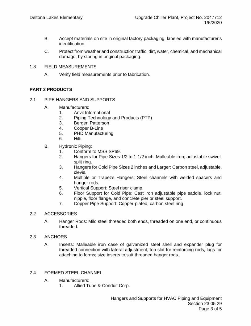
Deltona Lakes Elementary Upgrade Chiller Plant, Project No. 2047712 1/6/2020
Hangers and Supports for HVAC Piping and Equipment Section 23 05 29
Page 3 of 5
B. Accept materials on site in original factory packaging, labeled with manufacturer's identification.
C. Protect from weather and construction traffic, dirt, water, chemical, and mechanical damage, by storing in original packaging.
1.8 FIELD MEASUREMENTS
A. Verify field measurements prior to fabrication.
PART 2 PRODUCTS
2.1 PIPE HANGERS AND SUPPORTS
A. Manufacturers: 1. Anvil International 2. Piping Technology and Products (PTP) 3. Bergen Patterson 4. Cooper B-Line 5. PHD Manufacturing 6. Hilti.
B. Hydronic Piping: 1. Conform to MSS SP69. 2. Hangers for Pipe Sizes 1/2 to 1-1/2 inch: Malleable iron, adjustable swivel,
split ring. 3. Hangers for Cold Pipe Sizes 2 inches and Larger: Carbon steel, adjustable,
clevis. 4. Multiple or Trapeze Hangers: Steel channels with welded spacers and
hanger rods. 5. Vertical Support: Steel riser clamp. 6. Floor Support for Cold Pipe: Cast iron adjustable pipe saddle, lock nut,
nipple, floor flange, and concrete pier or steel support. 7. Copper Pipe Support: Copper-plated, carbon steel ring.
2.2 ACCESSORIES
A. Hanger Rods: Mild steel threaded both ends, threaded on one end, or continuous threaded.
2.3 ANCHORS
A. Inserts: Malleable iron case of galvanized steel shell and expander plug for threaded connection with lateral adjustment, top slot for reinforcing rods, lugs for attaching to forms; size inserts to suit threaded hanger rods.
2.4 FORMED STEEL CHANNEL
A. Manufacturers: 1. Allied Tube & Conduit Corp.

Deltona Lakes Elementary Upgrade Chiller Plant, Project No. 2047712 1/6/2020
Hangers and Supports for HVAC Piping and Equipment Section 23 05 29
Page 4 of 5
2. B-Line Systems 3. Midland Ross Corporation, Electrical Products Division 4. Unistrut Corp
B. Product Description: Galvanized 12 gage) thick steel. With holes 1-1/2 inches on center.
PART 3 EXECUTION
3.1 INSTALLATION - PIPE HANGERS AND SUPPORTS
A. Install in accordance with MSS SP 69.
B. Support horizontal piping as scheduled.
C. Install hangers with minimum 1/2 inch space between finished covering and adjacent work.
D. Place hangers within 12 inches of each horizontal elbow.
E. Use hangers with 1-1/2 inch minimum vertical adjustment.
F. Support vertical piping at every floor.
G. Where piping is installed in parallel and at same elevation, provide multiple pipe or trapeze hangers.
H. Support riser piping independently of connected horizontal piping.
I. Provide copper plated hangers and supports for copper piping.
J. Design hangers for pipe movement without disengagement of supported pipe.
K. Prime coat exposed steel hangers and supports. Hangers and supports located in crawl spaces, pipe shafts, and suspended ceiling spaces are not considered exposed.
L. Provide clearance in hangers and from structure and other equipment for installation of insulation.
3.2 PIPE HANGER SPACING SCHEDULE
Pipe Size
Spacing
Hanger
Rod
Steel Pipe 1/2 inch 6 feet, 0 inches 3/8 inch
3/4 to 1-1/4 inch 8 feet, 0 inches 3/8 inch
1-1/2, 2 inch 10 feet, 0 inches 3/8 inch
2-1/2 inch 10 feet, 0 inches 1/2 inch
3 inch 12 feet, 0 inches 1/2 inch
4 inch 14 feet, 0 inches 5/8 inch
5 inch 16 feet, 0 inches 5/8 inch
6 inch 16 feet, 0 inches 3/4 inch

Deltona Lakes Elementary Upgrade Chiller Plant, Project No. 2047712 1/6/2020
Hangers and Supports for HVAC Piping and Equipment Section 23 05 29
Page 5 of 5
Pipe Size
Spacing
Hanger
Rod
8 to12 inch 16 feet, 0 inches 7/8 inch
Pipe Size
Spacing
Hanger
Rod
Copper Pipe 1/2 inch 6 feet, 0 inches 3/8 inch
3/4 inch, 1 inch 8 feet, 0 inches 3/8 inch
1-1/4 to 2 inch 10 feet, 0 inches 3/8 inch
2-1/2 inch to 5 inch 12 feet, 0 inches 1/2 inch
6 inch and above 14 feet, 0 inches 3/4 inch
3.3 INSTALLATION - EQUIPMENT BASES AND SUPPORTS
A. Provide housekeeping pads of concrete, minimum 3-1/2 inches thick and extending 6 inches beyond supported equipment.
B. Using templates furnished with equipment, install anchor bolts, and accessories for mounting and anchoring equipment.
C. Construct supports of formed steel channel. Brace and fasten with flanges bolted to structure.
D. Provide rigid anchors for pipes after vibration isolation components are installed. Refer to Section 23 05 48 – Vibration Controls for HVAC Piping and Equipment.
3.4 PROTECTION OF FINISHED WORK
A. Protect adjacent surfaces from damage by installation.
END OF SECTION

Deltona Lakes Elementary Upgrade Chiller Plant, Project No. 2047712 1/6/2020
Mechanical Identification Section 23 05 54
Page 1 of 2
SECTION 23 05 54
MECHANICAL IDENTIFICATION
PART 1 GENERAL
1.1 SECTION INCLUDES PART 1 GENERAL ............................................................................................. 1
1.1 SECTION INCLUDES .................................................................. 1 1.2 SUBMITTALS .............................................................................. 1
PART 2 PRODUCTS .......................................................................................... 1 2.1 MECHANICAL IDENTIFICATION ................................................ 1
PART 3 EXECUTION ......................................................................................... 2 3.1 INSTALLATION - MECHANICAL IDENTIFICATION .................... 2 3.2 INSTALLATION – MECHANICAL WARRANTY SUMMARY NAMEPLATES ........................................................................................ 2
1.2 SUBMITTALS
A. Shop Drawings: Submit for mechanical identification list of wording, symbols, letter size, and color coding for mechanical identification and valve chart and schedule, including valve tag number, location, function, and valve manufacturer's name and model number.
B. Product Data: Mechanical Identification: Submit for mechanical identification manufacturers catalog literature for each product required.
PART 2 PRODUCTS
2.1 MECHANICAL IDENTIFICATION
A. Plastic Identification Nameplates: Laminated three-layer plastic with engraved black letters on light background color. Nameplate height to be 2” for small equipment, 3” for large equipment.
B. Plastic Warranty Nameplates: Laminated three-layer plastic with engraved black letters on light background color. Nameplate height as required to accommodate information.
C. Brass Valve Tags: Stamped 19GA (40 mil) brass with 1/2” high black filled lettering, 1-1/2 inches diameter. Brass beaded chain 4-1/2” long.
D. Plastic Pipe Markers: Factory fabricated, flexible, semi-rigid plastic, preformed to fit around pipe or pipe covering. Larger sizes may have maximum sheet size with spring fastener. Color and lettering to conform to ASME A13.1.
E. Plastic Tape Pipe Markers: Flexible, vinyl film tape with pressure sensitive adhesive backing and printed markings. Color and Lettering: Conform to ASME A13.1.

Deltona Lakes Elementary Upgrade Chiller Plant, Project No. 2047712 1/6/2020
Mechanical Identification Section 23 05 54
Page 2 of 2
PART 3 EXECUTION
3.1 INSTALLATION - MECHANICAL IDENTIFICATION
A. Plastic Nameplates: Install plastic nameplates indicating equipment ID with adhesive suitable for indoor or exterior use on all mechanical equipment.
B. Brass Valve Tags: Install valve tags with valve ID with corrosion resistant metal chain on all valves. Valve Chart: Provide laminated and framed valve schedule in mechanical room. Schedule to indicate Valve ID, purpose, and location if not immediately apparent.
C. Plastic Pipe Markers: Shall be installed to indicate fluid being conveyed and flow direction. 1. Install markers every 10’ on mains, at all branch take-offs and adjacent to
valves and cocks. 2. Apply to all exposed pipes, pipes behind removable tile ceiling, pipes in
concealed but accessible locations, such as behind access panels and at least once in each room.
3. Install pipe marker using pressure sensitive adhesive in accordance with the manufacturer's directions. The marker shall completely cover the circumference of the pipe and overlap itself minimum 1”.
3.2 INSTALLATION – MECHANICAL WARRANTY SUMMARY NAMEPLATES
A. Plastic Tags: Install plastic tags summarizing the following: 1. Warranty start date and end date 2. Extent of warranty (I.E. parts only) 3. Contractor Name and Phone Number
B. Adhere tag with two-sided tape to all equipment in a visible location.
END OF SECTION

Deltona Lakes Elementary Upgrade Chiller Plant, Project No. 2047712 1/6/2020
Testing, Adjusting, and Balancing for HVAC Section 23 05 93
Page 1 of 2
SECTION 23 05 93
TESTING, ADJUSTING, AND BALANCING FOR HVAC
PART 1 GENERAL
1.1 SECTION INCLUDES PART 1 GENERAL ............................................................................................. 1
1.1 SECTION INCLUDES .................................................................. 1 1.2 SUMMARY .................................................................................. 1 1.3 SUBMITTALS .............................................................................. 1 1.4 QUALITY ASSURANCE .............................................................. 1
PART 2 PRODUCTS .......................................................................................... 1 PART 3 EXECUTION ......................................................................................... 2
3.1 CALIBRATION ............................................................................. 2 3.2 EXAMINATION ............................................................................ 2 3.3 INSTALLATION TOLERANCES .................................................. 2 3.4 WATER SYSTEM PROCEDURE ................................................. 2 3.5 FIELD QUALITY CONTROL ........................................................ 2
1.2 SUMMARY
A. Section Includes: 1. Testing adjusting, and balancing of hydronic systems.
1.3 SUBMITTALS
A. Draft Reports: Submit for review prior to final acceptance of Project.
B. Test Reports: Submit prior to final acceptance of Project and for inclusion in operating and maintenance manuals. Assemble in soft cover, letter size, 3-ring binder, with table of contents page and tabs, and cover identification. Include reduced scale drawings with air outlets and equipment identified to correspond with data sheets, and indicating thermostat locations.
1.4 QUALITY ASSURANCE
A. Perform Work in accordance with AABC standards.
B. Report Forms: AABC MN-1 National Standards for Total System Balance forms, Forms prepared following ASHRAE 111, or NEBB forms.
PART 2 PRODUCTS
Not Used.

Deltona Lakes Elementary Upgrade Chiller Plant, Project No. 2047712 1/6/2020
Testing, Adjusting, and Balancing for HVAC Section 23 05 93
Page 2 of 2
PART 3 EXECUTION
3.1 CALIBRATION
A. Calibrate all sensors to the following tolerances: 1. Water temperature sensors to within 0.5 deg F of actual. 2. Pressure sensors to within 5% of actual.
3.2 EXAMINATION
A. Before starting work, verify systems are complete and operable.
B. Report defects, deficiencies, or abnormal conditions in mechanical systems preventing system balance.
C. Beginning of work means acceptance of existing conditions.
3.3 INSTALLATION TOLERANCES
A. Hydronic Systems: Adjust to within plus or minus 10 percent of design.
3.4 WATER SYSTEM PROCEDURE
A. Adjust water systems after air balancing to deliver design quantities within previously stated tolerances.
B. Use calibrated fittings or equipment and pressure gages to determine flow rates for system balance. Where not installed, base flow balance on temperature difference across heat transfer elements.
C. Change system balance with automatic control valves fully open to heat transfer elements.
D. Change adjustment of water distribution systems by means of balancing cocks, valves, and fittings.
3.5 FIELD QUALITY CONTROL
A. Verify recorded data represents actually measured or observed conditions.
B. Permanently mark settings of valves, dampers, and other adjustment devices. Set and lock memory stops.
C. Provide spot checking in the presence of the engineer. If any test data is found to be more than 5% from published TAB report, the TAB report shall be rejected and the contractor shall revise and reissue the report.
END OF SECTION

Deltona Lakes Elementary Upgrade Chiller Plant, Project No. 2047712 1/6/2020
Contractor Assisted Testing, Adjusting, and Balancing for HVAC Section 23 05 93
Page 1 of 2
SECTION 23 05 93.1
CONTRACTOR ASSISTED TESTING, ADJUSTING, AND BALANCING FOR HVAC
PART 1 GENERAL
1.1 SECTION INCLUDES PART 1 GENERAL ............................................................................................. 1
1.1 SECTION INCLUDES .................................................................. 1 1.2 SUMMARY .................................................................................. 1 1.3 RELATED DOCUMENTS ............................................................ 1 1.4 DESCRIPTION OF WORK .......................................................... 1
PART 2 PRODUCTS .......................................................................................... 1 PART 3 EXECUTION ......................................................................................... 2
3.1 OTHER PROCEDURES .............................................................. 2
1.2 SUMMARY
A. Section Includes: 1. Contractor assisted testing adjusting, and balancing of hydronic systems.
1.3 RELATED DOCUMENTS
A. Section 23 05 93.2 - Owner Furnished Testing, Adjusting, and Balancing for HVAC
1.4 DESCRIPTION OF WORK
A. Provide written notification of the construction progress to the Owner’s TAB agent a minimum of 2 weeks before TAB work is to be performed.
B. Provide all labor and materials to assistance to the Owner’s test and balance agent to complete the TAB work.
C. Contractor shall deliver one set of approved submittals to Owner test and balance contractor.
D. Any labor and material cost incurred by Owner Test and Balance Contractor due to lack of completed work, lack of cooperation, or inoperable equipment shall be back-charged to the Contractor.
PART 2 PRODUCTS
Not Used.

Deltona Lakes Elementary Upgrade Chiller Plant, Project No. 2047712 1/6/2020
Contractor Assisted Testing, Adjusting, and Balancing for HVAC Section 23 05 93
Page 2 of 2
PART 3 EXECUTION
3.1 OTHER PROCEDURES
A. Prior to requesting Owner Test and Balance, the Contractor shall: 1. Inspect installation of all systems and equipment. 2. Confirm proper and safe operation of all equipment. 3. Clean all strainers.
B. Provide labor and materials required by Owner's Test and Balance Contractor as necessary to obtain fully working systems as specified.
C. Should the systems require retesting due to fault of contractor (as deemed by the engineer) then the retest work shall be at the expense of the Contractor.
END OF SECTION

Deltona Lakes Elementary Upgrade Chiller Plant, Project No. 2047712 1/6/2020
Thermal Insulation Section 23 07 13
Page 1 of 6
SECTION 23 07 13
THERMAL INSULATION
PART 1 GENERAL
1.1 SECTION INCLUDES PART 1 GENERAL ............................................................................................. 1
1.1 SECTION INCLUDES .................................................................. 1 1.2 RELATED SECTIONS: ................................................................ 1 1.3 REFERENCES ............................................................................ 1 1.4 SUBMITTALS .............................................................................. 2 1.5 QUALITY ASSURANCE .............................................................. 2 1.6 QUALIFICATIONS ....................................................................... 2 1.7 DELIVERY, STORAGE, AND HANDLING ................................... 2 1.8 ENVIRONMENTAL REQUIREMENTS......................................... 2 1.9 FIELD MEASUREMENTS ............................................................ 2
PART 2 PRODUCTS .......................................................................................... 3 2.1 PIPE INSULATION ...................................................................... 3 2.2 EQUIPMENT INSULATION ......................................................... 3 2.3 JACKETING:................................................................................ 3
PART 3 EXECUTION ......................................................................................... 4 3.1 EXAMINATION ............................................................................ 4 3.2 PREPARATION ........................................................................... 4 3.3 INSTALLATION – PIPING ........................................................... 4 3.4 INSTALLATION – JACKETING:................................................... 4 3.5 INSTALLATION – EQUIPMENT INSULATION ............................ 4 3.6 INSTALLATION – PUMP INSULATION ....................................... 5 3.7 CLEANING .................................................................................. 5 3.8 REPAIR ....................................................................................... 5 3.9 PROTECTION OF FINISHED WORK .......................................... 5 3.10 INSULATION SCHEDULES ......................................................... 5
1.2 RELATED SECTIONS:
A. Section 23 21 23 – Hydronic Pumps: Product and execution requirements for pumps.
B. Section 23 05 01 – Pipework: Product and execution requirements for heating and cooling piping.
1.3 REFERENCES
A. ASTM International: 1. ASTM B209 - Aluminum and Aluminum-Alloy Sheet and Plate. 2. ASTM C518 - Steady-State Heat Flux Measurements and Thermal
Transmission Properties by Means of the Heat Flow Meter Apparatus. 3. ASTM E84 - Surface Burning Characteristics of Building Materials.

Deltona Lakes Elementary Upgrade Chiller Plant, Project No. 2047712 1/6/2020
Thermal Insulation Section 23 07 13
Page 2 of 6
4. ASTM E96 - Water Vapor Transmission of Materials.
B. National Fire Protection Association: 1. NFPA 255 - Surface Burning Characteristics of Building Materials.
C. Underwriters Laboratories 1. UL 723 - Surface Burning Characteristics of Building Materials.
1.4 SUBMITTALS
A. Section 15010 – General Mechanical Requirements: Submittal procedures.
B. Product Data: Submit product description, list of materials and thickness for each service or equipment scheduled and locations.
C. Manufacturer's Installation Instructions: Submit manufacturer's installation instructions for each product type.
1.5 QUALITY ASSURANCE
A. Perform Work in accordance with the Florida Building Code.
1.6 QUALIFICATIONS
A. Manufacturer: Company specializing in manufacturing Products specified in this section with minimum five (5) years experience.
B. Installer: Company specializing in performing Work of this section with minimum five (5) years experience.
1.7 DELIVERY, STORAGE, AND HANDLING
A. Section 23 05 01 –Mechanical General Requirements: Requirements for transporting, handling, storing, and protecting products.
B. Accept materials on site in original factory packaging, labeled with manufacturer's identification.
C. Protect from weather and construction traffic, dirt, water, chemical, and mechanical damage, by storing in original packaging.
1.8 ENVIRONMENTAL REQUIREMENTS
A. Do not insulate damp or wet systems.
B. Do not install insulation and related products when ambient temperatures and conditions are not meeting manufacturer’s requirements.
C. Maintain temperature before, during, and after installation for minimum period of 24 hours.
1.9 FIELD MEASUREMENTS
A. Verify field measurements prior to fabrication.

Deltona Lakes Elementary Upgrade Chiller Plant, Project No. 2047712 1/6/2020
Thermal Insulation Section 23 07 13
Page 3 of 6
PART 2 PRODUCTS
2.1 PIPE INSULATION
A. Manufacturers: 1. Childers Products Co. 2. Johns Manville 3. Owens Corning 4. Pittsburgh Corning Corp. 5. Armacell 6. K-Flex USA
B. Cellular Foam (Armaflex): ASTM C534; flexible, cellular elastomeric, molded or sheet. 1. k (ksi) Value: 0.27 at 75 degrees F. 2. Maximum Service Temperature: 220 degrees F. 3. Connection: Waterproof vapor retarder adhesive.
C. Cellular Glass (Foamglas): ASTM C552; 1. k (ksi) Value: 0.29 at 75 degrees F. 2. 8.0 lb/cu ft density 3. Vapor Retarder Jacket: ASJ jacket applied by the manufacturer to ASTMC-
1136 with integral flap for sealing joint.
2.2 EQUIPMENT INSULATION
A. Manufacturers: 1. Childers Products Co. 2. Johns Manville 3. Owens Corning 4. Pittsburgh Corning Corp.
B. Cellular Foam (Armaflex): ASTM C534; flexible, cellular elastomeric, molded or sheet. 1. k (ksi) Value: 0.27 at 75 degrees F. 2. Maximum Service Temperature: 220 degrees F. 3. Connection: Waterproof vapor retarder adhesive.
C. Cellular Glass (Foamglas): ASTM C552; 'k' factor of 0.29 at 75 degrees F; 8.0 lb/cu ft density. Field applied fiber reinforced mastic vapor barrier.
2.3 JACKETING:
A. Aluminum: Minimum 0.020 inch thick sheet, embossed finish, with longitudinal slip joints and 2 inch laps, die shaped fitting covers with factory applied PolySurlyn protective liner.
B. Flexible Wrap: Alumaguard by Polyguard Products: UV protective, rubberized bitumen, foil faced membrane with factory applied ‘peel and stick’ adhesive.

Deltona Lakes Elementary Upgrade Chiller Plant, Project No. 2047712 1/6/2020
Thermal Insulation Section 23 07 13
Page 4 of 6
PART 3 EXECUTION
3.1 EXAMINATION
A. Verify piping, equipment are tested and ready for installation.
3.2 PREPARATION
A. Surfaces to be insulated must be dry and free from surface rust and debris.
B. Use a wire brush to remove any surface rust.
3.3 INSTALLATION – PIPING
A. Continue insulation and vapor barrier through penetrations.
B. Locate insulation and cover seams in least visible locations.
C. Neatly finish insulation at supports, protrusions, and interruptions.
D. Insulate complete system of pipes conveying fluids below ambient temperature.
E. Cold Fluid Piping (Fluid temperature below 75 deg F): 1. Install insulation with complete vapor barrier jackets. Finish with glass cloth
and vapor barrier adhesive. 2. Insulate complete system.
F. Install insert between support shield and piping on piping 2 inches diameter or larger. Fabricate of high density insulating material suitable for temperature, not less than 6 inches long.
3.4 INSTALLATION – JACKETING:
A. Insulate pipe, fittings, joints, and valves.
B. Finish with glass mesh reinforced vapor barrier cement or integral vapor barrier provided by insulation manufacturer.
C. Cover with specified jacket with seams located on bottom side of horizontal piping. 1. Aluminum Jacketing: Secure with 1/2” wide aluminum bands max 12” OC.
3.5 INSTALLATION – EQUIPMENT INSULATION
A. Apply insulation to equipment by grooving, scoring, and beveling insulation. Secure insulation to equipment with studs, pins, clips, adhesive, wires, or bands.
B. Fill joints, cracks, seams, and depressions with bedding compound to form uniform surface. On cold equipment, use vapor barrier cement.
C. Cover cellular foam insulation with glass mesh reinforced vapor barrier cement.
D. Exterior Equipment - Install vapor barrier jacket. Insulate equipment, fittings, and joints and finish with glass mesh reinforced vapor barrier cement. Cover with aluminum jacket.
E. When equipment with insulation requires periodic opening for maintenance, repair, or cleaning, install insulation in to allow removal and replacement without damage.

Deltona Lakes Elementary Upgrade Chiller Plant, Project No. 2047712 1/6/2020
Thermal Insulation Section 23 07 13
Page 5 of 6
3.6 INSTALLATION – PUMP INSULATION
A. Chilled Water Pumps: 1. Pumps shall have cellular foam securely adhered to the entire impeller
head and suction diffuser and an easily removable aluminum box shall encase the insulation.
2. Aluminum Box: Provide a shop fabricated and reinforced aluminum box consisting of individual sections that allow easy removal and re-assembly. Sections shall fasten together with quality hasps. Seal between sections with foam tape. The interior of the box shall be insulated with 1” thick cellular foam insulation.
3.7 CLEANING
A. After work is complete, thoroughly clean the area of all insulation debris.
B. Remove mastic from adjacent surfaces.
3.8 REPAIR
A. After the Test and Balance agent completes their work, repair all insulation areas damaged.
3.9 PROTECTION OF FINISHED WORK
A. Insulation work shall be performed without applying undue stress or weight on installed piping and/or ductwork.
B. Contractor shall not allow workers to damage installed products.
3.10 INSULATION SCHEDULES
Pipe Insulation
Service Insulation Type Service Size
Thickness
Domestic Piping Exposed to Freezing
Cellular Foam painted with UV inhibitor paint
3” and less 0.75”
CHWS&R Above Ground – Exterior
Cellular Glass, aluminum Jacketed
All 2”
Flexible connections Cellular Foam (Match pipe jacketing)
All 1”
Equipment Insulation
Service Insulation Type Thickness
Expansion Tanks - Exterior Cellular Foam with Aluminum Jacket 2”
Chemical pot feeder and associated piping
Cellular Foam painted with UV inhibitor Mastic
0.75”
Air Separators - Exterior Cellular Foam with Aluminum Jacket 2”
Chiller Cold Surfaces (Not Factory Insulated)
Cellular Foam – Painted with UV protective paint
2”

Deltona Lakes Elementary Upgrade Chiller Plant, Project No. 2047712 1/6/2020
Thermal Insulation Section 23 07 13
Page 6 of 6
Chiller Insulation - All Apply flexible wrap jacketing n/a
END OF SECTION

Deltona Lakes Elementary Upgrade Chiller Plant, Project No. 2047712 1/6/2020
Startup of Mechanical Systems Section 23 08 02
Page 1 of 6
SECTION 23 08 02
STARTUP OF MECHANICAL SYSTEMS
PART 1 GENERAL
1.1 SECTION INCLUDES PART 1 GENERAL ........................................................................................... 1
1.1 SECTION INCLUDES .................................................................. 1 1.2 SUMMARY .................................................................................. 1 1.3 QUALITY ASSURANCE .............................................................. 1
PART 2 PRODUCTS – Not used ...................................................................... 2 PART 3 EXECUTION ....................................................................................... 2
3.1 EXAMINATION ............................................................................ 2 3.2 STARTUP/COMMISSION ............................................................ 2 3.3 REPORTING ............................................................................... 2 3.4 FORMS: ....................................................................................... 3
1.2 SUMMARY
A. Section Includes: 1. Start-up and commissioning of Mechanical equipment including:
a. VFD’s b. Chillers c. Pumps
2. Where the specifications do not require manufacturer startup, the contractor may provide qualified technicians to startup the equipment. If qualified technicians are not available, the contractor shall coordinate with the equipment manufacturer to have a factory technician startup the equipment.
3. Provide all labor, materials, and services necessary to complete the startup, safety verification, and adjustments needed for the equipment to perform in accordance with the construction documents for the mechanical equipment provided and/or modified as part of this contract.
1.3 QUALITY ASSURANCE
A. Perform Work in accordance with the Florida Building Code.
B. Provide qualified, knowledgeable technicians to perform startup and commission work.

Deltona Lakes Elementary Upgrade Chiller Plant, Project No. 2047712 1/6/2020
Startup of Mechanical Systems Section 23 08 02
Page 2 of 6
PART 2 PRODUCTS – Not used
PART 3 EXECUTION
3.1 EXAMINATION
A. Review the construction documents and applicable addenda and confirm the installation conforms to the documents. If needed, correct any deficiencies.
B. Review the installation for safety and notify the engineer of any unsafe conditions.
C. Review the accessibility to the equipment for maintenance purposes. Identify in writing, any items that may inhibit proper maintenance of the equipment.
3.2 STARTUP/COMMISSION
A. Perform the tasks contained on the following forms to insure that all work is completed and ready for test and balance. Indicate performance of each task by checking off items as they are completed. Where the forms require test results, provide the required data in a legible format (neatly handwritten is acceptable).
3.3 REPORTING
A. At the onset of construction, the Prime Contractor shall compile a startup/commissioning form notebook for all mechanical equipment requiring startup and commissioning on the project.
B. As equipment is installed and started, the contractor shall complete the appropriate forms and return them to the notebook. The contractor shall also fax a copy of the newly completed startup/commissioning forms to the engineer for review.
C. Prior to the processing of each pay application, the notebook will be reviewed by the engineer, and if necessary, the pay application will be adjusted to reflect the level of completion based upon equipment startup forms.
D. When a Test and Balance agent is designated for the project, the Prime Contractor shall provide an additional startup/commissioning notebook, containing copies of all current forms to the TAB contractor. The TAB agent shall then be copied with all subsequent startup/commissioning forms completed by the mechanical contractor.
E. Submit four copies (4) of the final, completed Startup Notebook with the closeout documentation for filing.

Deltona Lakes Elementary Upgrade Chiller Plant, Project No. 2047712 1/6/2020
Startup of Mechanical Systems Section 23 08 02
Page 3 of 6
3.4 FORMS:
A. The contractor shall utilize the forms on the following pages for startup and commissioning system components. If equipment specific forms are not provided, the contractor shall provide their standard startup form.

Deltona Lakes Elementary Upgrade Chiller Plant, Project No. 2047712 1/6/2020
Startup of Mechanical Systems Section 23 08 02
Page 4 of 6
GENERAL PROCEEDURES
Pre-Start-Up Inspection:
Verify proper equipment mounting and setting.
Verify that control, interlock and power wiring is complete.
Verify alignment of motors and drives.
Verify proper piping connections and accessories.
Verify that lubrication of equipment is completed.
Verify that instrumentation installation is completed.
Verify that hydronic systems have been cleaned and filled.
Verify that strainers are clean.
First Run Observations:
Verify direction of rotation.
Verify setting of safety controls including overload heater sizes.
Verify function of safety and operating controls.
Check motor loads against nameplate.
Purge air from hydronic systems.
Systems Start-up Checklist:
Rotating equipment has been aligned and belt drive tension has been adjusted.
Installation has been cleaned up and temporary coverings, stickers and tags removed.
Painted finishes have been touched up where damaged.
Equipment and piping identification work has been completed with valve tags, schedules, and piping identification system.
Fins on heat transfer coils have been combed out where damaged.
Graphic operational data such as start/stop instructions, valve tag schedules, and piping identification schedules have been provided where needed.
Water treatment program has been implemented, with initial qualitative testing of fluids in systems and domestic water supply, check of chemical feeder equipment, and instructions to chemical supplier as to results desired.

Deltona Lakes Elementary Upgrade Chiller Plant, Project No. 2047712 1/6/2020
Startup of Mechanical Systems Section 23 08 02
Page 5 of 6
AIR COOLED CHILLER START-UP DATA SHEET
Equipment Tag:
Manufacturer
Type
Model No
Serial No.
Voltage
Refrigerant Circuit #1 Refrigerant Circuit #2 (if applicable)
Compressor Amperage Compressor Amperage
Suction Pressure Suction Pressure
Discharge Pressure Discharge Pressure
Manufacturer Manufacturer
Type Type
Confirmed flow switch operation:
Chiller entering water temp
Chiller leaving water temp
Ambient temperature
Technician Name: Company Name: As the designated Equipment Startup Technician, I certify that this equipment is operating safely in accordance with the manufacturer’s guidelines. Technician Signature: Date:
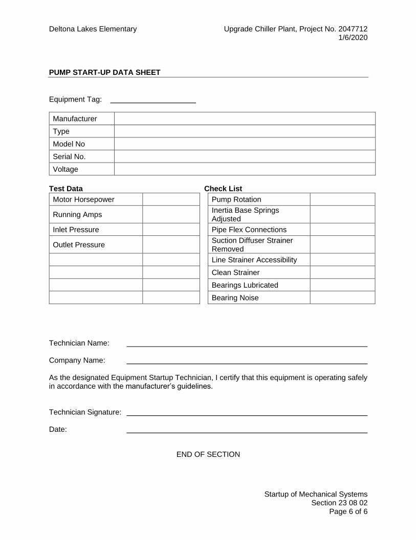
Deltona Lakes Elementary Upgrade Chiller Plant, Project No. 2047712 1/6/2020
Startup of Mechanical Systems Section 23 08 02
Page 6 of 6
PUMP START-UP DATA SHEET
Equipment Tag:
Manufacturer
Type
Model No
Serial No.
Voltage
Test Data Check List
Motor Horsepower Pump Rotation
Running Amps Inertia Base Springs
Adjusted
Inlet Pressure Pipe Flex Connections
Outlet Pressure Suction Diffuser Strainer
Removed
Line Strainer Accessibility
Clean Strainer
Bearings Lubricated
Bearing Noise
Technician Name: Company Name: As the designated Equipment Startup Technician, I certify that this equipment is operating safely in accordance with the manufacturer’s guidelines. Technician Signature: Date:
END OF SECTION

Deltona Lakes Elementary Upgrade Chiller Plant, Project No. 2047712 1/6/2020
VCSD ELECTRIC AND ELECTRONIC CONTROL SYSTEM FOR HVAC
Section 23 09 33 Page 1 of 28
SECTION 23 09 33
VCSD ELECTRIC AND ELECTRONIC CONTROL SYSTEMS FOR HVAC
PART 1 GENERAL
1.1 SUMMARY A. Section Includes:
PART 1 GENERAL ............................................................................................. 1 1.1 SUMMARY .................................................................................. 1 1.2 BID PROCEDURES ..................................................................... 2 1.3 SCOPE – GENERAL ................................................................... 2 1.4 SCOPE – EXPAND EXISTING CONTROL SYSTEM .................. 4 1.5 RELATED DOCUMENTS: ........................................................... 4 1.6 ABBREVIATIONS ........................................................................ 4 1.7 REFERENCES ............................................................................ 5 1.8 QUALITY ASSURANCE .............................................................. 6 1.9 SYSTEM PERFORMANCE ......................................................... 8 1.10 COORDINATION ......................................................................... 8 1.11 SUBMITTALS .............................................................................. 9 1.12 WARANTEE ...............................................................................10 1.13 BAS ACCEPTANCE PROCEDURE ............................................11 1.14 TRAINING ..................................................................................12 1.15 CLOSEOUT PROCEDURES ......................................................12
PART 2 PRODUCTS .........................................................................................13 2.1 ACCEPTABLE MANUFACTURERS/SYSTEM INTEGRATORS: 13 2.2 COMMUNICATIONS ..................................................................13 2.3 SOFTWARE KEY .......................................................................13 2.4 SYSTEM APPLICATIONS ..........................................................14 2.5 GRAPHICAL INTERFACE (LOCAL AND REMOTE) ...................17 2.6 CONTROL UNITS ......................................................................17 2.7 POWER SUPPLIES, LINE FILTERING, AND ELECTRICAL ACCESSORIES .....................................................................................19 2.8 INPUT AND OUTPUT INTERFACE ............................................20 2.9 ELECTRONIC SENSORS, INDICATORS, TRANSDUCERS AND COMPONENTS ......................................................................................21 2.10 ELECTRIC COMPONENTS ........................................................22 2.11 AUXILIARY CONTROL DEVICES ..............................................23
PART 3 EXECUTION ........................................................................................24 3.1 EXAMINATION ...........................................................................24 3.2 INSTALLATION ..........................................................................25 3.3 GRAPHICS .................................................................................27 3.4 VERIFICATION ...........................................................................27 3.5 DEMONSTRATION ....................................................................28
B. SUMMARY
1. This section defines the basic materials and methods and minimum equipment and performance requirements for the Building Automation

Deltona Lakes Elementary Upgrade Chiller Plant, Project No. 2047712 1/6/2020
VCSD ELECTRIC AND ELECTRONIC CONTROL SYSTEM FOR HVAC
Section 23 09 33 Page 2 of 28
System (BAS) in order to provide the functions necessary for control of the mechanical and other specified systems on this project.
2. The implied and stated intent of the drawings and specifications is to establish minimum acceptable quality standards for device-level integration of material and equipment as well as workmanship and to provide a complete and operable BAS.
3. The drawings are diagrammatic intending to show a workable general arrangement and location of components and are not necessarily complete or rigid in all details.
1.2 BID PROCEDURES A. The existing site BAS manufacturer is:
1. KMC. B. The work occurs on a site with an existing BAS. Therefore, the manufacturer of
the existing system is the only acceptable BAS manufacturer. C. As a prequalification for inclusion on the District’s acceptable System Integrator
list, the SI has pre-negotiated labor and material costs with the District. D. The prime contractor’s bid submittal shall include a full breakout of the labor and
materials proposed by the SI for use on the project. A summary page shall be included where costs are shown to total the SI contractor’s price to the prime contractor. A statement of compliance with the pre-negotiated pricing shall be included and signed by an official of the SI contractor.
E. Failure to submit the required documentation with the bid package may result in bid disqualification.
1.3 SCOPE – GENERAL A. The Building Automation System (BAS) is to provide a peer-to-peer networked,
stand-alone, distributed control system for building mechanical and electrical systems. The BAS shall include an operator workstation also known as Engineering Control Center (ECC), field programmable microprocessor based control units panels, instrumentation end control devices, wiring, piping, and related systems to provide centralized and facility wide control functions.
B. The BAS shall be designed such that each mechanical and electrical system will be able to operate under stand-alone control. As such, in the event of a network communication failure, or the loss of any other controller, the control system shall continue to independently operate under control.
C. The System Integrator (SI) Contractor shall refer to the drawings and equipment specifications for coordination of factory installed control equipment in products furnished by others as they relate to this section.
D. Provide all labor (direct employed or subcontracted), materials, programming and supervision necessary to install a complete Building Automation System (BAS) per the construction documents. Include provisions for the following: 1. Mounting hardware for all control devices. 2. Construction supervision. 3. Startup and verify proper operation of control equipment. 4. Point verification and testing of hardware and software. 5. Work in conjunction with the TAB agent to calibrate and adjust devices as
required.

Deltona Lakes Elementary Upgrade Chiller Plant, Project No. 2047712 1/6/2020
VCSD ELECTRIC AND ELECTRONIC CONTROL SYSTEM FOR HVAC
Section 23 09 33 Page 3 of 28
6. Warrantee. E. The BAS as specified herein shall be provided in its entirety by the SI Contractor.
The SI Contractor shall base their bid on the system as specified, the sequence of operation, the point’s list (Input/Output Summary) and contract documents. The documentation pertaining to the BAS is schematic in nature. The SI Contractor shall provide equipment and labor not specifically referred to herein or on the plans, that are required to meet the functional intent, shall be provided without additional cost to the owner.
F. The SI shall provide all electrical control and interlock wiring connected to the controls and instrumentation systems.
G. All 110 VAC or greater voltage power wiring to main control panels shall be provided by Division 16 Contractor (Electrical), and coordinated by this Contractor. Failure of this contractor to coordinate requirements with other divisions shall result in the SI contractor being responsible for any non-coordinated items.
H. All 24 VAC control power to operate equipment shall be the responsibility of this contractor.
I. All conduits in connection with the controls and instrumentation system shall be furnished and installed by this Contractor.
J. The Control Contractor shall install all sensing and control components. K. Provide a comprehensive operator and technician-training program as described
herein. L. Provide as-built documentation, software, and all DDC control logic and all
associated support documentation on approved media, which accurately represents the final installed system.
M. Adjustments of manual balancing devices, as required to obtain design air and/or water flows, shall be by the TAB Contractor. The controls contractor shall provide assistance to the TAB Contractor with control adjustments as required to obtain design flows by: 1. Providing on-site instruction on the proper interfacing and operation of the
equipment. 2. Providing the necessary software for use with the balancing contractor's
personal computer for interfacing with their control equipment. Where proprietary equipment is required, this equipment shall be provided for the Balancing Contractor's use.
3. Provide 2-hours of onsite for the Balancing Contractor to instruct on proper use of the software and interface with the control system.
N. To ensure compatibility and training standards with the present VCSD Building Automation Systems, the BAS must be fully software certified at the time of installation to provide interoperability and backward compatibility to the BAS systems currently installed by the successful BAS manufacturer. The BAS must use only latest versions of database software and tools for area controllers, configuring the system, and for the present graphical user interface (GUI) which is used by the building operator.
O. Demolition: The controls contractor shall remove all unused controls, including devices, controllers, conduit, control tubing, and wire. VCSD shall have the right of first refusal for all hardware removed. Demolition shall be complete with

Deltona Lakes Elementary Upgrade Chiller Plant, Project No. 2047712 1/6/2020
VCSD ELECTRIC AND ELECTRONIC CONTROL SYSTEM FOR HVAC
Section 23 09 33 Page 4 of 28
exposed surfaces and finishes restored to match the surrounding area. Coordinate work with other trades.
1.4 SCOPE – EXPAND EXISTING CONTROL SYSTEM 1. The System Integrator shall expand the existing campus BAS hardware
and software to incorporate equipment indicated in the Drawings and control it in the manner indicated in the Sequence of Operations.
2. The EMS expansion shall include all labor and materials to provide the following: a. Upgrade existing site software, if required b. Upgrade existing site hardware, if required. c. Incorporate new equipment into the existing database. d. Incorporate new equipment into the existing graphics hierarchy. e. All controls devices shown on the drawings and required to meet
the sequence of operations. f. Program control sequences. g. Interconnection to site control system. h. Interconnect all onsite BAS devices with Owner’s central Building
Automation and Control System via Owner’s Ethernet system. i. Provide installation and calibration, supervision, adjustments, and
fine tuning necessary for complete and fully operational system.
1.5 RELATED DOCUMENTS: A. Sequence of Operations: Refer to Drawings. B. Drawings and general provisions of the Contract, including General and
Supplementary Conditions. C. Division-1, General Requirements, of these Specifications. D. The General Conditions of the Contract, Supplementary Conditions, and General
Requirements bound herewith are a part of these Specifications and shall be used in conjunction with this Division as a part of the Contract Documents. Consult them for further instructions pertaining to this work. Contractors shall be responsible for and be governed by all requirements thereunder.
1.6 ABBREVIATIONS A. The acronym shown below are abbreviations used or referenced throughout this
section of the specification. 1. AGC Application Generic Controller 2. AI Analog Input 3. AMR Automated Meter Reading 4. AO Analog Output 5. API Application Program Interface 6. ASC Application Specific Controller 7. ASP Application Service Provider 8. BAS Building Automation System 9. CAC Custom Application Controller 10. CPU Central Processing Unit 11. DDC Direct Digital Controller 12. DDE Dynamic Data Exchange

Deltona Lakes Elementary Upgrade Chiller Plant, Project No. 2047712 1/6/2020
VCSD ELECTRIC AND ELECTRONIC CONTROL SYSTEM FOR HVAC
Section 23 09 33 Page 5 of 28
13. DI Digital Input 14. DO Digital Output 15. EP Electric-pneumatic 16. FACP Fire Alarm Control Panel 17. FCC Fire Command Center 18. GC Global Controller 19. I/O Input/Output 20. IP Internet Protocol 21. ISS Intelligent Space Sensor 22. KLAN Local Area Network 23. LC Local Controller 24. ODBC Open Database Connectivity 25. PE Pneumatic-electric 26. PID Proportional-Integral-Derivative 27. PLC Programmable Logic Controller 28. PPM Parts per million 29. SI System Integrator 30. SID Supervisory Interface Device (Gateways) 31. SMS Short Message System 32. TCP/IP Transmission-Control Protocol/Internet Protocol 33. TUC Terminal Unit Controller 34. UC Unitary Controller 35. WAN Wide Area Network 36. WET Web-Enabled Technology 37. XIF External Interface File 38. XML Extensible Markup Language
1.7 REFERENCES A. The publications listed below form a part of this specification to the extent
referenced. The publications are referred to in the text by the basic designation only. All publications shall be the latest edition that is recognized and accepted by the local governing authorities. 1. Air Movement and Control Association (AMCA)
a. AMCA 502 – Damper Application Manual b. AMCA 610 – Methods of Testing Airflow Measurement Stations
for Ratings. 2. American Society of Heating, Refrigeration, & Air Conditioning Engineers,
Inc. a. ASHRAE 114 – Energy Management Control System
Instrumentation b. ASHRAE Guideline 4 – Preparation of Operating and
Maintenance Documentation for Building Systems. c. ASHRAE Guideline 14P – Measurement of Energy and Demand
Savings 3. American Society of Mechanical Engineers (ASME)
a. ASME CSD-1 – Control & Safety Devices for Automatically Fired Boilers
b. ASME PTC-22 – Digital Systems Techniques

Deltona Lakes Elementary Upgrade Chiller Plant, Project No. 2047712 1/6/2020
VCSD ELECTRIC AND ELECTRONIC CONTROL SYSTEM FOR HVAC
Section 23 09 33 Page 6 of 28
4. American Society for Testing and Materials (ASTM) 5. Institute of Electrical and Electronic Engineers (IEEE)
a. IEEE std 1143 – Guide on shielding Practice for Low-Voltage cable
b. IEEE STD 37.13 – standard for Low- Voltage AC Power Circuit Breakers Used in Enclosures.
c. IEEE STD 37.14 – Standard for Low – Voltage DC Power Circuit Breakers used in Enclosure.
d. IEEE std 62.22 – Guide for the Application of Metal-Oxide surge arresters for Alternating Circuit Systems
e. IEEE std C62.34 – Standard for Performance of Low-Voltage surge Protective Devices
f. IEEE std C62.36 – Standard Test Methods for surge-protectors used in Low-Voltage AC Power Circuits
g. IEEE std C62.41 – Recommended Practice on Surge Voltage in Low Voltage AC Power Circuits
h. IEEE STD C62.45 – Guide on Surge Testing for Equipment Connected to Low – Voltage AC Power Circuits.
i. IEEE std C62.62 – Standard Test Specification for Surge – Protective Devices for Low – Voltage AC Power Circuits
6. The Instrumentation Systems and Automation Society a. ISA 575.01 Flow Equation for Sizing Control Valves
7. National Electrical Contractors Association a. NECA 101 – Standard for Installing Conduit (Rigid, IMC, EMT) b. NECA 1 – Standard for Good Workmanship in Electrical
Contracting 8. National Electrical Manufacturers Association (NEMA)
a. NEMA WC57 – Control Cable b. NEMA WD6 – Wiring Devices-Dimensional Requirements
9. Nation al Fire Protection Association (NFPA) a. NFPA 70 – National Electrical Code b. NFPA 90A – Standard for the Installation of Air Conditioning and
Ventilation Systems c. NFPA 90B – Standard for the Installation for Warm Air Heating
and Air Conditioning Systems d. NFPA 92A – Recommended Practices for Smoke Control
Systems 10. Sheet Metal and Air Conditioning Contractors’ National Association
(SMACNA) a. SMACNA – Energy Systems Analysis and Management b. SMACNA – HVAC Systems – Applications c. SMACNA – HVAC Systems – Commissioning Manual d. SMACNA – Indoor Air Quality – A Systems Approach
11. Underwriters Laboratories (UL)
1.8 QUALITY ASSURANCE A. Products:

Deltona Lakes Elementary Upgrade Chiller Plant, Project No. 2047712 1/6/2020
VCSD ELECTRIC AND ELECTRONIC CONTROL SYSTEM FOR HVAC
Section 23 09 33 Page 7 of 28
1. All products of the BAS shall be provided with appropriate agency approvals. With the submittal documents, verification that the approvals exist for all submitted products shall be provided. Systems or products not currently offering one or more of the following approvals are not acceptable: a. UL-916; Energy Management Systems b. UL-873; Temperature Indication and Regulating Equipment c. UL-864, Subcategories UUKL, UOXX, UDTZ; Fire Signaling and
Smoke Control Systems d. FCC, Part 15, Subpart J, Class A Computing Devices Emissions
Requirements 2. Electrical Standards: Provide electrical products that have been tested,
listed and labeled by UL and comply with NEMA standards. 3. NEMA Compliance: Comply with NEMA standards pertaining to
components and devices for electrical control systems. 4. NFPA Compliance: Comply with NFPA 90A "Standard for the Installation
of Air Conditioning And Ventilating Systems" where applicable to controls and control sequences.
5. National Codes: Perform Work in accordance with the Florida Building Code.
B. Manufacturers: 1. Firms regularly engaged in the manufacture of products specified, of
types and sizes required, whose products have been in satisfactory use in similar service for not less than 5 years.
C. System Integrator: 1. The SI Contractor shall provide Licensed Trade Technicians to furnish,
engineer, and install the BAS. They shall be skilled and factory trained, certified, and authorized by the manufacturer for debugging, start-up, diagnostics, training, service and repair of all components to ensure interoperability.
2. The SI Contractor shall be designated by the BAS Equipment Manufacturer as a current Authorized Agent for their products in the territory where the equipment is to be installed.
3. The SI shall be regularly engaged in the service and installation of the BAS proposed for the project, and shall have been so for a minimum of three (3) years in central Florida using the current company name. Experience as a company with a different name shall not be considered.
4. The SI shall have an office within 50 miles of Volusia County that is staffed with BAS designers trained in integrating interoperable systems and technicians fully capable of providing BAS instruction and routine emergency maintenance service on all system components of the system to be installed.
D. Software Programmer 1. The SI Contractor shall provide a software programmer to oversee the
project that is highly experienced in projects with similar size and scope. The SI Contractor shall submit along with project submittal data the qualifications and specific project experience of the programmer intended to be used on the project. If, upon review by the engineer, the

Deltona Lakes Elementary Upgrade Chiller Plant, Project No. 2047712 1/6/2020
VCSD ELECTRIC AND ELECTRONIC CONTROL SYSTEM FOR HVAC
Section 23 09 33 Page 8 of 28
programmer is deemed insufficiently experienced, the SI Contractor shall remove the programmer from the project and provide the qualifications and experience of an alternative programmer until an acceptably qualified individual is selected.
1.9 SYSTEM PERFORMANCE A. Performance Standards. The system shall conform to the following:
1. Graphic Display. The system shall display a quality graphic with the capability for a minimum of 20 dynamic points. All current data shall be displayed within 10 seconds of the request. The graphic shall be intuitive and shall present data in a graphical, not tabular, format.
2. Graphic Refresh. The system shall update all dynamic points with current data within 10 seconds.
3. Object Command. The maximum time between the command of a binary object by the operator and the reaction by the device shall be 10 seconds. Analog objects shall start to adjust within 10 seconds.
4. Object Scan. All changes of state and change of analog values shall be transmitted over the high-speed network such that any data used or displayed at a controller or workstation will be current, within the prior 60 seconds.
5. Alarm Response Time. The maximum time from when an object goes into alarm to when it is annunciated at the workstation shall not exceed 45 seconds.
6. Program Execution Frequency. Custom and standard applications shall be capable of running as often as once every 5 seconds. The Contractor shall be responsible for selecting execution times consistent with the mechanical process under control.
7. Performance. Programmable Controllers shall be able to execute DDC PID control loops at a selectable frequency from at least once every 5 seconds. The controller shall scan and update the process value and output generated by this calculation at this same frequency.
8. Multiple Alarm Annunciation. All workstations on the network shall receive alarms within 5 seconds of each other.
1.10 COORDINATION A. The following products are to be furnished by the controls contractor and
installed by others. The controls contractor shall coordinate installation locations. 1. Hydronic Piping Components:
a. Control valves. b. Immersion wells. c. Flow switches. d. Temperature sensor wells and sockets. e. Gage taps. f. Flow meters. g. Couplings for flow and pressure switches
B. The Mechanical Contractor is responsible for providing and installing blank-off plates if needed when the control application requires dampers smaller than duct size. The controls contractor shall coordinate this requirement.

Deltona Lakes Elementary Upgrade Chiller Plant, Project No. 2047712 1/6/2020
VCSD ELECTRIC AND ELECTRONIC CONTROL SYSTEM FOR HVAC
Section 23 09 33 Page 9 of 28
C. The controls contractor shall be responsible for the following: 1. Coordination of all controls items with other trades. 2. Coordination of wall space for panels. 3. Coordination of all wall-mounted sensor locations with furniture. 4. Coordination of space sensors to avoid diffuser throw patterns.
1.11 SUBMITTALS A. General:
1. Pre-Submittal Conference: After award of the Construction Contract, and prior to delivering submittal data to the Engineer, the BAS Contractor shall schedule a pre-submittal conference with the Engineer. The purpose of the pre-submittal conference is to review the proposed system concept and to discuss the sequence of construction activities.
2. Refer to the specification Division 1 – General Requirements for submittal format.
3. Coordinate with the Mechanical contractor to determine the number of submittals required. Provide a minimum of five copies of all submittal data.
4. Product Requirements: Provide shop drawings and other submittals on hardware, software, and equipment to be installed or furnished. Begin no work until submittals have been approved for conformity with design intent. When manufacturer's cutsheets apply to a product series rather than a specific product, clearly indicate applicable data by highlighting or by other means. Clearly reference covered specification and drawing on each submittal. General catalogs shall not be accepted as cutsheets to fulfill submittal requirements. Select and show in submittal quantities of products appropriate to scope of work. Submittal approval does not relieve Contractor of responsibility to supply sufficient quantities to complete work.
B. The following data/information shall be submitted for review (prior to ordering any hardware or software items): 1. Overall system interconnecting diagrams showing all remote panels (PCs,
Field Panels, and LAN devices), and power/surge protection locations and Uninterrupted Power Supply (UPS).
2. Distributed panel locations (site and/or building plan, as appropriate to identify physical locations).
3. Valve and damper schedules showing size, configuration, capacity, Manufacturer and location.
4. Data sheets for all hardware and software control components. 5. Thermostat/sensor locations. 6. A brief written description of the methodology used to keep graphics files
on various PC terminals updated and consistent with one another. (Remote computer graphics vs. site computer)
7. A detailed point-to-point diagram of circuitry of all DDC panels. Submit on a per distributed panel basis. Typical are accepted, provided all applicable units are listed and the units are identified.
8. A list of connected data points, including connected control unit and input or output devices.

Deltona Lakes Elementary Upgrade Chiller Plant, Project No. 2047712 1/6/2020
VCSD ELECTRIC AND ELECTRONIC CONTROL SYSTEM FOR HVAC
Section 23 09 33 Page 10 of 28
9. A detailed Sequence of Operations derived from the design intent shown on the Contract Drawings. Retyping the Sequence of Operations in the Contract Drawings is not acceptable.
10. Detailed documentation on the specific field equipment to be supplied by the Controls Contractor shall be submitted and approved prior to installations; including, but not limited to, actuators, valves, temperature sensors, surge protection, and damper operators.
11. The control valve schedule shall include each valve's unique identifier, size, flow coefficient Cv, pressure drop at specified flow rate, actuator size, close-off pressure data, dimensions, and access and clearance requirements data. Valve schedules may be submitted in advance but shall be included in the complete submittal.
12. All schemes and methods proposed to provide lightning protection for the DDC system, entering and leaving each building shall be submitted for review and approval.
13. Complete bill of materials to identify and quantify all devices. 14. Submit a color printout of each graphic. The graphic shall show
temperature, status, position and all data points that will appear on the screen. If acceptable to the engineer, the graphics may be submitted on disk in a standard graphic format.
C. Record Submittals: 1. Within one week after substantial completion, submit final copies of the
submittals modified to reflect all changes during construction. Electronic data shall be submitted in AutoCad v2004 format on CD-ROM disks. Provide one original and one duplicate.
2. Submit the same number of record submittals that are required for the pre-construction submittals (minimum of 5 copies).
3. All programs, code, databases, graphic files, CAD drawings, and symbol libraries generated for operation of the system shall be included as part of the system documentation. This information shall be submitted both in hardcopy bound format and machine-readable format (i.e., CD ROM). Two (2) copies of the machine-readable form shall be submitted.
4. Complete original issue documentation, installation, operation manuals, and supporting software for all third-party hardware and software furnished and installed as part of the system or required for the operation of the system, including remote terminals, user's computer work station, monitors, graphics and memory boards, network servers, printers, and modems.
5. All software licenses, warranty certificates and documentation for all hardware and software including third party hardware and software shall be provided.
1.12 WARANTEE A. The entire BAS provided under this contract, including all control devices
provided by this Contractor, shall be warranted to be free of defects in workmanship and material for a period of TWO (2) years from the date of Substantial Completion. Any equipment found to be defective during this period shall be repaired and/or replaced without expense to the Owner. The Contractor

Deltona Lakes Elementary Upgrade Chiller Plant, Project No. 2047712 1/6/2020
VCSD ELECTRIC AND ELECTRONIC CONTROL SYSTEM FOR HVAC
Section 23 09 33 Page 11 of 28
shall accomplish this work during normal working hours (8 a.m. to 5 p.m., Monday through Friday, excluding holidays).
B. The Contractor shall respond to all warranty items within one working day from when they are reported. Provide a report to the VCSD Maintenance Department identifying the problem, the devices affected and the nature of the repair or replacement.
C. The warranty shall cover all costs for parts, labor, associated travel, any software sequence modifications, and expenses throughout the warranty period.
D. Throughout the duration of the prime contractor’s warrantee, all BAS warrantee issues and communications shall be routed through the prime contractor. After the prime contractor’s warrantee expires, the SI shall coordinate directly with the VCSD Maintenance department regarding warrantee issues for the duration of the BAS warrantee.
1.13 BAS ACCEPTANCE PROCEDURE A. The SI shall perform a three-phase commissioning procedure consisting of field
I/O calibration and commissioning, system commissioning and integrated system program commissioning. Document all commissioning information on commissioning data sheets, which shall be submitted prior to acceptance testing. Commissioning work, which requires shutdown of system or deviation from normal function, shall be performed when the operation of the system is not required. The commissioning must be coordinated with the owner and prime contractor to ensure systems are available when needed. Notify the operating personal in writing of the testing schedule so that authorized personnel from the owner and prime contractor are present throughout the commissioning procedure.
B. After control devices have been commissioned (i.e. calibrated, tested and signed off), each BAS program shall be put on line and commissioned. The SI Contractor shall, in the presence of the owner’s representative and/or engineer, demonstrate each programmed sequence of operation and compare the results in writing. In addition, each control loop shall be tested to verify proper response and stable control, within specified accuracy’s. System program test results shall be recorded on commissioning data sheets and submitted for record. Any discrepancies between the specification and the actual performance will be immediately rectified and retested.
C. The SI Contractor shall submit printed graphical trend logs of Building Automation System (BAS) points to demonstrate that the HVAC systems are functioning as designed. Trend intervals shall be typically on an hourly basis, and trends shall be run for a minimum of 2 weeks, 24 hours a day. Trended points shall include as a minimum: 1. All temperature points (air and hydronic) and active setpoints 2. All relative humidity points 3. Damper and valve position points 4. Selected status points. 5. All ventilation airflow rates and active setpoints
D. A variety of historical data collection utilities shall be provided to manually or automatically sample, store, and display system data for all system points:

Deltona Lakes Elementary Upgrade Chiller Plant, Project No. 2047712 1/6/2020
VCSD ELECTRIC AND ELECTRONIC CONTROL SYSTEM FOR HVAC
Section 23 09 33 Page 12 of 28
1. Digital Controllers (DC’s) shall store point history data for selected analog and digital inputs and outputs: a. Any point, physical or calculated, may be designated for trending. b. Any point, regardless of physical location in the network, may be
collected and stored in each Digital Controller’s (DC’s) point group.
2. Each Digital Controller (DC) shall have a dedicated RAM-based buffer for trend data and shall be capable of storing data samples.
3. The Network shall contain sufficient trend storage capacity, either in memory or on hard drive, to retain the last 72 hourly values for every system point shown on the Input/Output Summary, including software points. Trend data shall be displayed at the printer or at any network terminal.
1.14 TRAINING A. Training sessions shall be provided for Owner’s personnel by the SI Contractor’s
factory trained control engineers and technicians. B. The SI Contractor shall conduct an 8-hour on-site training course for designated
Owner’s personnel in maintenance and operation of control system.
1.15 CLOSEOUT PROCEDURES A. Provide a duplicate of the final resident software on magnetic media, along with
instructions on downloading procedures and long-term storage of the media. B. Provide pre-programmed access codes to all levels. Subject to Owners
approval. C. Ownership of proprietary material: All project developed hardware and software
shall become the property of the Owner. These include but are not limited to: 1. Project graphic images, 2. Record drawings, 3. Project database, 4. Job-specific application programming code, 5. All documentation for project hardware and software.
D. Provide the following closeout information: 1. Operating and maintenance data.
a. Manufacturer’ catalog data and specifications on components used in system.
b. Detailed instructions for operations of system. c. Operator’s reference table listing addresses of connected input
points and output points. Show settings where applicable. d. Programmer’s manual including information necessary to perform
programming functions. e. Language manual including information necessary to perform
programming functions. f. Flow charts of software programs utilized in DDC system. g. Complete program listing file and parameter listing file for
programs. h. Copy of warranty. i. Operating and maintenance cautions and instructions.
Deltona Lakes Elementary Upgrade Chiller Plant, Project No. 2047712 1/6/2020
VCSD ELECTRIC AND ELECTRONIC CONTROL SYSTEM FOR HVAC
Section 23 09 33 Page 13 of 28
j. Recommended spare parts list. 2. Owner instruction report. 3. Performance verification report. 4. Guarantee letter.
PART 2 PRODUCTS
2.1 ACCEPTABLE MANUFACTURERS/SYSTEM INTEGRATORS: A. KMC Controls, Inc. / ABC Controls
2.2 COMMUNICATIONS A. On-site communications between BAS components shall be accomplished via a
dedicated, hardwired Local Area Network (LAN). Individual BAS components shall pass data to the network by the use of directly connection to the network or by passing data through higher level building control units.
B. The BAS shall connect to the existing district-wide peer-to-peer network for remote communications. Modem dial-up systems are not acceptable.
C. Inputs, outputs, and control variables used to integrate control strategies across multiple controllers shall be readable by each controller on the LAN. Program and test all cross-controller links required to execute control strategies specified on Drawings. An authorized operator shall be able to edit cross-controller links by typing a standard object address or by using a point-and-click interface.
D. LAN capacity shall be not less than 60 stations or nodes. E. Minimum LAN data speed shall be 38 Kbps. F. Transmission Medium
1. Inside buildings: Fiber optic or single pair of solid 24 gauge twisted, shielded copper cable.
2. Between buildings: Fiber optic run underground and in conduits. If existing communication medium is available that meets these requirements and the Owner provides written approval, the SI may be utilized it for BAS communications. If existing communication medium is not available or usable, the SI shall provide the medium. The minimum conduit size for underground communication shall be one (1) inch diameter. Install two extra spare pairs in each conduit run.
G. Wireless communications are NOT allowed. H. System shall automatically synchronize controller time clocks daily from an
operator-designated controller via the LAN. If applicable, system shall automatically adjust for daylight saving and standard time.
I. System shall be expandable to at least twice the required input and output objects with additional controllers, associated devices, and wiring.
J. Provide updated software on the master host PC located at the central facilities maintenance department and any on-site PC’s as necessary for site-based FMT’s or administration access as required by the location.
2.3 SOFTWARE KEY A. Where access to the EMS software is limited by security programming, the
controls contractor shall provide two (2) EMS software keys (hardware or software keys) for the owner’s indefinite use.

Deltona Lakes Elementary Upgrade Chiller Plant, Project No. 2047712 1/6/2020
VCSD ELECTRIC AND ELECTRONIC CONTROL SYSTEM FOR HVAC
Section 23 09 33 Page 14 of 28
2.4 SYSTEM APPLICATIONS A. Each Workstation shall provide for an operator interface and off-line storage of
system information. Provide the following applications at each workstation. 1. Manual Database Save and Restore: A system operator with the proper
password clearance shall be able to archive the database from any system panel and store on magnetic media. The operator shall also be able to clear a panel database and manually initiate a download of a specified database to any panel in the system.
2. System Configuration: The Workstation Software shall provide a graphical method of configuring the system. The user with proper security shall be able to add new devices, assign modems to devices, and obtain a visual riser diagram of the system. This shall allow for future system changes or additions.
3. On-Line Help: Provide a context sensitive, on line help system to assist the operator in operation and editing of the system. On line help shall be available for all applications and shall provide the relevant data for that particular screen. Additional help information shall be available through the use of hypertext.
4. Security: Each operator shall be required to log on to the system with a user name and password in order to view, edit, add, or delete data. System security shall be selectable for each operator. The system supervisor shall have the ability to set passwords and security levels for all other operators. Each operator password shall be able to restrict the operator’s access for viewing and/or changing each system application, full screen editor, and object. Each operator shall automatically be logged off of the system if no keyboard or mouse activity is detected. This auto logoff time shall be set per operator password. All system security data shall be stored in an encrypted format.
5. System Diagnostics: The system shall automatically monitor the operation of the Workstation, printer, modem, network connections, and Control Panels. The failure of any device shall be annunciated to the operator workstation.
6. Alarm Processing: Any object in the system shall be configurable to alarm in and out of normal state. The operator shall be able to configure the alarm limits, warning limits, states, and reactions for each object in the system. a. Alarm Reactions: The operator shall be able to determine what
actions, if any, are to be taken, by object (or point), during an alarm. Actions shall include logging, printing, starting programs, displaying messages, dialing out to remote stations, paging, providing audible annunciation or displaying specific system graphics. Each of these actions shall be configurable by Workstation and time of day. An object in alarm that has not been acknowledged within an operator specified time period shall be re-routed to an alternate operator specified alarm receipt device.
b. Binary Alarms: Each binary object shall be set to alarm based on the operator-specified state. Provide the capability to disable

Deltona Lakes Elementary Upgrade Chiller Plant, Project No. 2047712 1/6/2020
VCSD ELECTRIC AND ELECTRONIC CONTROL SYSTEM FOR HVAC
Section 23 09 33 Page 15 of 28
alarming when the associated equipment is turned off or is being serviced.
c. Analog Alarms: Each analog object shall have both high and low alarm limits and warning limits. Alarming must be able to be automatically and manually disabled.
7. Trend Logs: The operator shall be able to define a custom trend log for any data in the system. This definition shall include interval, start-time, and stop-time. Trend intervals of 1, 5, 15, 30, and 60 minutes as well as once a shift (8 hours), once a day, once a week, and once a month shall be selectable. All trends shall start based on the hour. Each trend shall accommodate a minimum of 10 system objects. The system operator with proper password shall be able to determine how many samples are stored in each trend. Trend data shall be sampled and stored on the Building Controller panel and be archived on the hard disk. Trend data shall be able to be viewed and printed from the operator interface software. They shall also be storable in a tab delimited ASCII format for use by other industry standard word processing and spreadsheet packages.
8. Alarm and Event Log: The operator shall be able to view all logged system alarms and events from any location in the system. Events shall be listed chronologically. An operator with the proper security level may acknowledge and clear alarms. All that have not been cleared by the operator shall be archived to the hard disk on the workstation.
9. Object and Property Status and Control: Provide a method for the operator with proper password protection to view, and edit if applicable, the status of any object and property in the system. These statuses shall be available by menu, on graphics, or through custom programs.
10. Clock Synchronization: The real time clocks in all building control panels and workstations shall be synchronized on command of an operator. The system shall also be able to automatically synchronize all system clocks, daily from any operator-designated device in the system. The system shall automatically adjust for daylight savings and standard time if applicable.
11. Reports and Logs: Provide a reporting package that allows the operator to select, modify, or create reports. Each report shall be definable as to data content, format, interval, and date. Report data shall be archived on the hard disk for historical reporting. Provide the ability for the operator to obtain real time logs of designated lists of objects. Reports and logs shall be stored on the PC hard disk in a format that is readily accessible by other standard software applications including spreadsheets and word processing. Reports and logs shall be readily printed to the system printer. Provide the capability for the operator to easily define any system data into a daily, weekly, monthly, or annual report. These reports shall be time and date stamped and shall contain a report title and the name of the facility.
12. Workstation Editors: Each PC Workstation shall support full screen editing of all system applications. Provide editors for each application at
Deltona Lakes Elementary Upgrade Chiller Plant, Project No. 2047712 1/6/2020
VCSD ELECTRIC AND ELECTRONIC CONTROL SYSTEM FOR HVAC
Section 23 09 33 Page 16 of 28
the PC workstation. The applications shall be downloaded and executed at the appropriate controller panels.
13. Controller: Provide a full screen editor for each type controller and application that shall allow the operator with proper password to view and change the configuration, name, control parameters, and system setpoints.
14. Scheduling: An editor for the scheduling application shall be provided at each Workstation. Provide a monthly calendar for each schedule. Exception schedules and holidays shall be shown clearly on the calendar. Provide a method for allowing several related objects to follow a schedule. The advance and delay time for each object shall be adjustable from this master schedule. a. An operator with proper password level shall be able to modify the
schedule. Schedules shall be able to be easily copied between objects and/or dates.
15. Equipment Coordination: Provide a full screen editor that allows equipment to be grouped for proper operation as specified in the sequence of operations.
16. Custom Application Programming. Provide the tools to create, modify, and debug custom application programming. The operator shall be able to create, edit, and download custom programs at the same time that all other system applications are operating. The system shall be fully operable while custom routines are edited, compiled, and downloaded. The programming language shall have the following features: a. The language shall be English language oriented and be based on
the syntax of programming languages such as BASIC. It shall allow for free form or fill in the blank programming. Alternatively, the programming language can be graphically-based using function blocks as long as blocks are available that directly provide the functions listed below, and that custom or compound function blocks can be created.
b. A full screen character editor/programming environment shall be provided. The editor shall be cursor/mouse-driven and allow the user to insert, add, modify, and delete code from the custom programming. It shall also incorporate word processing features such as cut/paste and find/replace.
c. The programming language shall allow independently executing program modules to be developed. Each module shall be able to independently enable and disable other modules.
d. The editor/programming environment shall have a debugging/simulation capability that allows the user to step through the program and to observe any intermediate values and or results. The debugger shall also provide error messages for syntax and execution errors.
e. The programming language shall support conditional statements (IF/THEN/ELSE/ELSE-IF) using compound Boolean (AND, OR, and NOT) and/or relations (EQUAL, LESS THAN, GREATER THAN, NOT EQUAL) comparisons.
Deltona Lakes Elementary Upgrade Chiller Plant, Project No. 2047712 1/6/2020
VCSD ELECTRIC AND ELECTRONIC CONTROL SYSTEM FOR HVAC
Section 23 09 33 Page 17 of 28
f. The programming language shall support floating point arithmetic using the following operators: +, -, /, x, square root, and xy. The following mathematical functions shall also be provided: natural log, log, absolute value, and minimum/maximum value from a list of values.
g. The programming language shall have pre-defined variables that represent clock time, day of the week, and date. Variables that provide interval timing shall also be available. The language shall allow for computations using these values.
h. The programming language shall have ability to pre-defined variables representing the status and results of the System Software, and shall be able to enable, disable, and change the values of BACnet objects in the system.
2.5 GRAPHICAL INTERFACE (LOCAL AND REMOTE) A. Both the Local and Remote Graphical Interfaces shall provide the following:
1. Dynamic points shall include analog and binary values, dynamic text, static text, and animation files. Graphics shall have the ability to show animation by shifting image files based on the status of the point.
2. The graphics shall be of good quality and shall be consistent throughout the BAS interface providing the user with visual description of the status of the system.
3. Links shall be provided to easily move between data screens. Cross-links shall also be provided to jump to central equipment screens.
4. Provide “drill-down” ability to allow the user to obtain the desired information easily.
B. Standard Building Display: Each floor of each building shall be provided with an independent BAS screen that displays all sensed space temperatures and relative humidity levels. If any space temperature is more than 2 degrees from setpoint, the space shall be displayed as Yellow in color. If any space is more than 4 degrees from setpoint, it shall be displayed as Red in color. If any space relative humidity is above 65% RH, the sensed space shall be displayed as Red in color.
C. Graphics shall display in Standard Inch Pounds.
2.6 CONTROL UNITS A. General: Provide Building Controllers (BC), Advanced Application Controllers
(AAC), Application Specific Controllers (ASC), and Smart Actuators (SA) that conform to the following:
B. Communication: 1. Service Port: Each controller shall provide a service communication port
for connection to a Portable Operator's Terminal. 2. Signal Management: BC and ASC operating systems shall manage input
and output communication signals to allow distributed controllers to share real and virtual object information and to allow for central monitoring and alarms.
3. Data Sharing: Each BC and AAC shall share data as required with each networked BC and AAC.

Deltona Lakes Elementary Upgrade Chiller Plant, Project No. 2047712 1/6/2020
VCSD ELECTRIC AND ELECTRONIC CONTROL SYSTEM FOR HVAC
Section 23 09 33 Page 18 of 28
4. Stand-Alone Operation: Each piece of equipment shall be controlled by a single controller to provide stand-alone control in the event of communication failure. All I/O points specified for a piece of equipment shall be integral to its controller. Provide stable and reliable stand-alone control using default values or other method for values normally read over the network.
C. Environment: Controller hardware shall be suitable for anticipated ambient conditions. 1. Controllers used outdoors or in wet ambient conditions shall be rated for
operation at 20°F to 140°F. 2. Controllers used in conditioned space shall be rated for operation at 32°F
to 120°F. D. Enclosures: Controller enclosures shall be of adequate size and style to allow all
housed components to be easily serviced. 1. Provide locking type, metal cabinet, with common keying. Panels screwed
closed are not acceptable. The enclosures shall have a metal print pocket suitable for storing wiring, service and log information.
2. Indoor panels shall be NEMA 1 enclosures with gaskets. 3. Outdoor panels shall be NEMA 3R. 4. Outdoor panels installed East of US-95 or in cooling tower or chemically
treated areas shall be NEMA 4X. 5. Enclosures shall physically isolate 120v power and 24v power and each
shall be clearly labeled. E. Keypad: Provide a local keypad and display for each BC and AAC. Operator
shall be able to use keypad to view and edit data. Keypad and display shall require password to prevent unauthorized use. If the manufacturer does not normally provide a keypad and display for each BC and AAC, provide the software and any interface cabling needed to use a laptop computer as a Portable Operator's Terminal for the system.
F. Real-Time Clock: Controllers that perform scheduling shall have a real-time clock.
G. Serviceability: 1. Controllers shall have diagnostic LEDs for power, communication, and
processor. 2. Wires shall be connected to a field-removable modular terminal strip or to
a termination card connected by a ribbon cable. 3. Each BC and AAC shall continually check its processor and memory
circuit status and shall generate an alarm on abnormal operation. System shall continuously check controller network and generate alarm for each controller that fails to respond.
H. Memory: 1. Controller memory shall support operating system, database, and
programming requirements. 2. Each BC and AAC shall permanently retain application programming in
nonvolatile memory in the event of power loss. 3. Each ASC and SA shall use nonvolatile memory and shall retain BIOS
and application programming in the event of power loss.

Deltona Lakes Elementary Upgrade Chiller Plant, Project No. 2047712 1/6/2020
VCSD ELECTRIC AND ELECTRONIC CONTROL SYSTEM FOR HVAC
Section 23 09 33 Page 19 of 28
2.7 POWER SUPPLIES, LINE FILTERING, AND ELECTRICAL ACCESSORIES A. Power Line Filtering: Provide internal or external transient voltage and surge
suppression for workstations and controllers. 1. Surge protection shall have:
a. Dielectric strength of 1000 V minimum b. Response time of 10 nanoseconds or less c. Transverse mode noise attenuation of 65 dB or greater d. Common mode noise attenuation of 150 dB or greater at 40-100
Hz 2. Surge suppression shall comply at a minimum with manufacturer’s
requirements and shall include suppression on all lines entering and leaving each building.
3. All communication channels between PC, Global and Unitary Controllers whether in conduits or overhead runs, shall have transient suppression networks installed. The transient (Surge) protection must meet IEEE standard C37.90a-1974. The suppression network shall be automatic, self-restoring and be on active duty at all times.
B. Power Supplies: Control transformers shall be UL listed. Furnish Class 2 current-limiting type or furnish over-current protection in primary and secondary circuits for Class 2 service in accordance with NEC requirements. Limit connected loads to 80% of rated capacity. 1. DC power supply output shall match output current and voltage
requirements. Unit shall be full-wave rectifier type with output ripple of 5.0 mV maximum peak-to-peak. Regulation shall be 1.0% line and load combined, with 100-microsecond response time for 50% load changes. Unit shall have built-in over-voltage and over-current protection and shall be able to withstand 150% current overload for at least three seconds without trip-out or failure. a. Unit shall operate between 32°F and 120°F. EM/RF shall meet
FCC Class B. b. Line voltage units shall be UL recognized. c. Transformers shall be mounted in an auxiliary panel or other
suitable accessible location with disconnecting means. Provide a pilot light for each transformer, to indicate the presence of load power.
C. Controller Wiring Requirements: 1. Provide all necessary 24 VAC transformers, 24 VAC power distribution
wiring, etc. to controllers for a complete operating system. 2. Terminal fittings or insulating bushings shall be used to protect wiring
associated with controllers at enclosures, junction boxes, etc. D. Wiring and Conduit
1. The contractor shall provide all DDC and related control wiring and conduit. Wire and cable shall be pulled from device or control point to the DDC, Auxiliary, or LPI panels. All wire and cable shall be labeled and tagged 4 inches down from the point at which the wire enters the cabinet with the corresponding point number.
2. All indoor exposed control wiring shall be run in EMT; outdoor exposed control wiring shall be run in PVC conduit.

Deltona Lakes Elementary Upgrade Chiller Plant, Project No. 2047712 1/6/2020
VCSD ELECTRIC AND ELECTRONIC CONTROL SYSTEM FOR HVAC
Section 23 09 33 Page 20 of 28
3. All wiring routed in non-exposed (above ceiling) areas shall utilize plenum-rated cabling and be properly supported using J-hooks or cable rings.
4. All cable runs exposed in return air plenums shall be smoke rated for the application and secured to the building structure.
5. Control wiring for 24-volt circuits shall be rated for 300-volt service. 6. All PVC and EMT conduit and outlet boxes shall conform to the
requirements specified under Division 16, Electrical. 7. All conductors shall be of stranded copper wire. 8. Conduits shall be sized on a maximum fill of 40% capacity. 9. Data transmission cabling and equipment grounding procedures shall
meet the latest FCC guidelines for electromagnetic field generation. 10. All control wiring sizes and types shall meet the equipment
manufacturer's recommendations. 11. DDC Wiring and Cable Requirements for New DDC Panels:
a. Digital Output *Minimum #14 AWG THHN b. Digital Input *Teflon jacketed twisted pair #16 -or- #16
AWG THHN minimum c. Analog Output *Twisted pair NEC-rated CMP #20 AWG d. Analog Input *Twisted pair NEC-rated CMP #20 AWG e. Data Transmission *Teflon jacketed twisted shielded pair #24
AWG 12-1/2 pico-ferrad, 6 twists/foot f. *Wire sizes listed for lengths up to 750'.
12. All junction boxes and couplings on conduit containing DDC related wiring shall be painted a sky blue color.
2.8 INPUT AND OUTPUT INTERFACE A. General: Hard-wire input and output points to BCs, AACs, ASCs, or SAs. B. Protection. Shorting an input or output point to itself, to another point, or to
ground shall cause no controller damage. Input or output point contact with up to 24 V for any duration shall cause no controller damage.
C. Binary Inputs: Binary inputs shall monitor the on and off signal from a remote device. Binary inputs shall provide a wetting current of at least 12 mA and shall be protected against contact bounce and noise. Binary inputs shall sense dry contact closure without application of power external to the controller.
D. Pulse Accumulation Inputs: Pulse accumulation inputs shall conform to binary input requirements and shall accumulate up to 10 pulses per second.
E. Analog Inputs: Analog inputs shall monitor low-voltage (0-10 Vdc), current (4-20 mA), or resistance (thermistor or RTD) signals. Analog inputs shall be compatible with and field configurable to commonly available sensing devices.
F. Binary Outputs: Binary outputs shall send an on-or-off signal for on and off control. Building Controller binary outputs shall have three-position (on-off-auto) override switches and status lights. Outputs shall be selectable for normally open or normally closed operation. Separate relays with HOA switches and status lights may be used to meet this requirement.
G. Analog Outputs: Analog outputs shall send a modulating 0-10 Vdc or 4-20 mA signal as required to properly control output devices. Analog outputs shall not drift more than 0.4% of range annually.
Deltona Lakes Elementary Upgrade Chiller Plant, Project No. 2047712 1/6/2020
VCSD ELECTRIC AND ELECTRONIC CONTROL SYSTEM FOR HVAC
Section 23 09 33 Page 21 of 28
H. Tri-State Outputs: Control three-point floating electronic actuators without feedback with tri-state outputs (two coordinated binary outputs). Tri-State outputs may be used to provide analog output control in zone control and terminal unit control applications such as VAV terminal units, duct-mounted heating coils, and zone dampers.
I. Universal Inputs and Outputs: Inputs and outputs that can be designated as either binary or analog in software shall conform to the provisions of this section that are appropriate for their designated use.
2.9 ELECTRONIC SENSORS, INDICATORS, TRANSDUCERS AND COMPONENTS A. Outside Air Master Temperature Sensor
1. Single point outside air temperature RTD shall be 1000-ohm thin film platinum resistor sensor with 4-20 mA 2-wire output transmitter with solar shield.
2. Approved Manufacturers: a. System Integrator’s brand named product. b. Hy-Cal c. Viasala d. ACI
B. Vivarium Temperature and Humidity Sensors: (for wet service) 1. Room temperature RTD shall be 100 ohm platinum sensor with 4-20 mA
2-wire output transmitter. Transmitter shall be waterproof or shall be remote mounted. Cover shall be rustproof, and shall be protected by a SS “U”-shaped guard firmly attached to the wall.
2. Room humidity sensor shall have a 4-20 mA 2-wire output transmitter, 0-100% relative humidity range, accuracy of +/- 2% RH, shall be waterproof, and shall be resistant to chlorine and other cleaning agents. Cover shall be rustproof, and shall be protected by a SS “U”-shaped guard firmly attached to the wall.
3. Combination units shall comply with the above, but shall be mounted in a single, waterproof, rustproof enclosure, and shall be protected by a SS “U”-shaped guard firmly attached to the wall.
4. Approved Manufacturers: a. System Integrator’s brand named product. b. Hy-Cal c. Viasala d. TCS e. General Eastern f. Siemens g. ACI
C. Liquid Flow Meters: (Insertion Electromagnetic type) 1. Liquid flow measurement sensor shall be of the electromagnetic flow
meter type and shall be bi-directional, microprocessor-based, with insertion style mounting.
2. Product shall be complete with all installation hardware necessary to enable insertion and removal of the meter without system shutdown. Wetted metal components shall be 316 SS. The flow meter shall average velocity readings from two sets of diametrically opposed electrodes.

Deltona Lakes Elementary Upgrade Chiller Plant, Project No. 2047712 1/6/2020
VCSD ELECTRIC AND ELECTRONIC CONTROL SYSTEM FOR HVAC
Section 23 09 33 Page 22 of 28
3. Each flow meter shall be individually wet-calibrated against a primary volumetric standard that is accurate to within 0.1% and traceable to NIST. A certificate of calibration shall be provided with each flow meter. a. Accuracy shall be within ± 1% of rate from 2-20 ft/s. b. Overall turndown shall exceed 100:1.
4. Output signals shall be completely isolated and shall consist of the following: a. (1) analog output; 4-20mA, 0-10V, or 0-5V jumper selectable, b. (1) scalable dry contact output for totalization c. (1) high resolution frequency output for use with peripheral
devices such as an ONICON display module or Btu meter. d. FB-3500 for Bi-directional applications shall provide additional
contact outputs for direction and flow totalization in each direction. 5. Product: Onicon FB-3500 Series (or approved equal)
D. Current Transducer 1. Provide a solid state transducer to monitor current level sensed by the
internal current transformer. Internal circuits are to be totally powered by induction from the line being monitored.
2. Size transducer based upon equipment monitored to operate within manufacturer’s recommended range.
3. Accuracy: within 2% FSO 4. Output:4-20 mA 5. Mounting: Foot style 6. Approved Manufacturer:
a. Kele CX E. Current Sensing Switches
1. Provide a solid state switch which closes when the current level sensed by the internal current transformer exceeds the trip point. Internal circuits are to be totally powered by induction from the line being monitored.
2. All devices that are not “direct drive” (using flex couplings or belts) shall utilize adjustable threshold current switches to enable detection of changes in motor amp draw upon drive failure.
3. The CS shall be a self gripping split-core type with optional mounting feet bracket; shall be isolated to 600 VAC rms; and shall have an adjustable mounting bracket for installation flexibility.
4. Output shall be N.O., Solid State, 1.0 A @ 30 VAC/DC with a minimum aperture of 0.52”X0.68” for motor power feed.
5. Approved Manufacturer: a. Veris Industries Hawkeye model #H800.
2.10 ELECTRIC COMPONENTS A. Differential Pressure Switches:
1. Differential pressure switches shall be furnished as indicated by the sequence for status purposes for either air or water applications.
2. Provide single pole double throw switch with fully adjustable differential pressure settings. The switch shall have a snap-acting Form C contact rated for the application.
3. The switch contact shall be rated for 5 amps at 120 volts as a minimum.

Deltona Lakes Elementary Upgrade Chiller Plant, Project No. 2047712 1/6/2020
VCSD ELECTRIC AND ELECTRONIC CONTROL SYSTEM FOR HVAC
Section 23 09 33 Page 23 of 28
4. Units shall be selected for ranges consistent with the application and shall be submitted for the Engineer’s approval.
5. Pressure rating of switch and connecting tubing: a. Fan - Rated for 12 inches WC. b. Pump – Maximum deadhead system pressure.
6. Switches used for safety shutdown applications shall be of the manual reset type.
7. Approved Manufacturers: a. System Integrator’s brand named product. b. Honeywell c. Siemens d. Dwyer e. Cleveland Airflow f. Mamac
B. Control Relays and Contactors: 1. Relays shall be a minimum DPDT, of proper coil voltage, with neon
indicator light, and of sufficient rating for specified purpose. Relay base shall be of the screwed terminal type.
2. Contactors shall be definite purpose type, have adequate number of poles, of proper coil voltage, and of sufficient rating for specified purpose. Contactors used for DDC interface control shall contain a Hand-Off-Auto switch.
3. Approved Manufacturers: a. System Integrator’s brand named product. b. Dayton c. Siemens d. Allen-Bradley e. GE f. Square D g. Veris
2.11 AUXILIARY CONTROL DEVICES A. 2-way Control Valves (Pressure Dependent)
1. Control valves shall be two-way type for two-position or modulating service as scheduled or shown. a. Close-off (differential) Pressure Rating: 200 psi.
2. Water Valves: a. Body and trim style and materials shall be per manufacturer's
recommendations for design conditions and service shown, with equal percentage ports for modulating service.
b. Sizing Criteria: Two-position service: Line size. Two-way modulating service: Pressure drop shall be equal to
twice the pressure drop through heat exchanger (load), 50% of the pressure difference between supply and return mains, or 5 psi, whichever is greater.
Valves 1/2" through 2" shall be bronze body or cast brass ANSI Class 250, spring loaded, Teflon packing, quick opening
Deltona Lakes Elementary Upgrade Chiller Plant, Project No. 2047712 1/6/2020
VCSD ELECTRIC AND ELECTRONIC CONTROL SYSTEM FOR HVAC
Section 23 09 33 Page 24 of 28
for two-position service. Two-way valves to have replaceable composition disc, or stainless steel ball.
2-1/2" valves and larger shall be cast iron ANSI Class 125 with guided plug and Teflon packing.
c. Acceptable Manufacturer: Delta. Belimo KMC Product by Specified Control System Manufacturer (with prior
approval on each project only) B. Electronic Valve Operators
1. Description: a. The actuator shall have electronic overload or digital rotation
sensing circuitry to prevent damage to the actuator throughout the rotation of the actuator.
b. Where shown, an internal mechanical, spring return mechanism shall be built into the actuator housing.
c. All rotary spring return actuators shall be capable of both clockwise and counter clockwise spring return operation. Linear actuators shall spring return to the retracted position.
d. Proportional actuators shall accept a 0-10 VDC or 0-20 ma control signal and provide a 2-10 VDC or 4-20 ma operating range.
e. All 24 VAC/DC actuators shall operate on Class 2 wiring and shall not require more than 10 VA for AC or more than 8 W for DC applications.
f. All non-spring return actuators shall have an external manual gear release to allow manual positioning of the damper when the actuator is not powered. Spring return actuators with more than 60 in-lb. torque capacity shall have a manual crank for this purpose.
g. All modulating actuators shall have an external, built-in switch to allow the reversing of direction of rotation
h. Actuators shall be provided with a conduit fitting and a minimum 1m electrical cable and shall be pre-wired to eliminate the necessity of opening the actuator housing to make electrical connections.
i. Actuators shall be Underwriters Laboratories Standard 873 listed. j. Actuators shall be designed for a minimum of 60,000 full stroke
cycles at the actuator's rated torque. 2. Special Warrantee: Provide a 5 year materials warrantee. 3. Acceptable Manufacturers:
a. Belimo b. Product by Specified Control System Manufacturer (with prior
approval on each project only)
PART 3 EXECUTION
3.1 EXAMINATION
Deltona Lakes Elementary Upgrade Chiller Plant, Project No. 2047712 1/6/2020
VCSD ELECTRIC AND ELECTRONIC CONTROL SYSTEM FOR HVAC
Section 23 09 33 Page 25 of 28
A. Verify equipment is installed and prepared for controls connections. B. Verify conditioned power supply is available to control units and to operator
workstation. C. Verify field end devices, and wiring is installed prior to installation proceeding.
3.2 INSTALLATION A. General:
1. Install Work in accordance with the Florida Building Code. 2. Remove any unused items that are part of renovations or demolition,
including, but not limited to: conduit, wire, tubing, controllers, controlled devices, relays, enclosures, etc. Do not abandon in place.
3. Locate all control components and accessories such that they are easily accessible for adjustment, service and replacement.
4. The control system shall be completely installed and ready for operation. 5. Dielectric isolation shall be provided where dissimilar metals are used for
connection and support. 6. Penetrations through and mounting holes in the building exterior shall be
made watertight. Penetrations through fire and smoke rated assemblies shall maintain fire and/or smoke rating.
7. Devices mounted in or on piping or ductwork, on building surfaces, in mechanical/electrical spaces, or in occupied space ceilings shall be installed in accordance with manufacturer's recommendations and as shown. Control devices to be installed in piping and ductwork shall be provided with required gaskets, flanges, thermal compounds, insulation, piping, fittings, and manual valves for shutoff, equalization, purging, and calibration.
8. Where control devices are installed on insulated piping or ductwork provide standoff brackets or thermal wells sized to clear insulation thickness. Provide extended sensing elements actuator or linkages, and other accessories as required.
9. Install control systems and materials in accordance with manufacturer’s instructions, industry standards, rough-in drawings, and detail drawings. Install electrical components complying with the requirements of Electrical. Mount all control panels at convenient locations and heights.
10. Identify each item, mounted on the face of a control panel, with an engraved nameplate (1/4” high engraved letters minimum). Identify each item of control equipment (except room sensors and thermostats), with stamped tape, firmly attached to equipment (1/4” high letters minimum).
11. Thermostats or sensors mounted on outside walls shall be mounted on 1” minimum thickness, rigid fiberglass insulating base (or equal).
12. All thermostat bulbs in water lines shall be installed inseparable wells, packed with heat conductive compound.
13. All controllers, relays, transducers, etc., required for stand-alone control shall be housed in NEMA and UL listed enclosures with a lockable door. The type of NEMA enclosure shall be based upon environmental requirements outlined in the specifications or on the drawings for this project.

Deltona Lakes Elementary Upgrade Chiller Plant, Project No. 2047712 1/6/2020
VCSD ELECTRIC AND ELECTRONIC CONTROL SYSTEM FOR HVAC
Section 23 09 33 Page 26 of 28
14. DDC components that are to be factory mounted shall be provided by the SI Contractor and shipped to the equipment manufacturer for installation. Coordination of the factory installation shall be the responsibility of the SI Contractor. Proper operation of factory installed components shall be the responsibility of the SI Contractor.
B. Communication and signal wire installation requirements: 1. Install all exposed wiring external to control panels, including low-voltage
wiring, in EMT. Wiring shall be installed without splices between control devices and DDC panels.
2. Plan and coordinate routing with other disciplines. 3. Do not interfere with equipment access. 4. Provide flexible metallic conduit where equipment mounting is flexible. 5. Seal penetrations into air moving equipment including inside conduit.
C. Enclosures 1. Use panduits in each control panel to organize and conceal all wiring. 2. Fuse all transformers. 3. Control panels shall be clearly identified by labels (2” lettering). 4. Provide and install as-built wiring diagrams to indicate the control points
on all equipment. 5. Provide laminated point lists in all control panels.
D. Control Units 1. Install control units and other hardware in position on permanent walls
where not subject to excessive vibration. 2. Install software in control units and in operator workstation. Implement
features of programs to specified requirements and appropriate to sequence of operation. Refer to Sequence of Operations.
3. Provide 120 volts alternating current, 15 amp dedicated power circuit to each programmable control unit.
4. Provide surge suppressor at each programmable control unit. 5. Install electrical material and installation in accordance with appropriate
requirements of Division 16. E. Outside Air Master Temperature Sensor
1. Coordinate with Owner to determine location. 2. Anchor securely to structure.
F. High Precision Temperature Sensors 1. Install sensors in locations with adequate distance from mixing points to
ensure complete mixing. G. Pressure and Flow Sensors
1. Install in locations that ensure accurate sensing. 2. Avoid areas that will interfere with maintenance access.
H. Liquid Flowmeters 1. Flowmeters shall be installed with at least 10 diameter of straight pipe
length upstream and five diameter of straight pipe length down stream. I. Current Sensors
1. Motor Status: The contractor shall provide and install a Current Sensing switch on any motor required to have motor status. One phase of the motor power feed shall be routed through the aperture of the current sensing switch.

Deltona Lakes Elementary Upgrade Chiller Plant, Project No. 2047712 1/6/2020
VCSD ELECTRIC AND ELECTRONIC CONTROL SYSTEM FOR HVAC
Section 23 09 33 Page 27 of 28
J. Control Valves and Actuators 1. Install control valve actuator vertically (above the pipe) whenever
possible. 2. Valves installed such that the actuator is below a horizontal position will
not be accepted. 3. Provide ample maintenance access. 4. Permanently mark shaft as to indicate valve position 5. Install in accordance with manufacturers written instructions, rough-in
drawings, and detail drawings.
3.3 GRAPHICS A. The SI shall create site layout color graphics that form an intuitive dynamic
hierarchal graphical interface for displaying data generally configured as follows: B. First Level – Campus-wide data:
1. Campus site plan with drill-down links to individual buildings. 2. Campus CHWS and CHWR temperatures for campuses with hydronic hot
water systems. 3. Campus HWS and HWR temperatures for campuses with hydronic hot
water systems. 4. If any space temperature or relative humidity level in a building is in an
alarm state, the building graphic shall be displayed in red. C. Second Level – Building specific data:
1. The second level graphic screen shall provide the building floor plan with the HVAC system ductwork and equipment diagrammatically shown.
2. Individual space temperatures shall be displayed. 3. The follow data shall also be displayed, if available.
a. Relative humidity levels. b. HVAC Supply air temperatures. c. Operating mode. d. For Central Plants, show equipment alarms.
D. Third Level – Equipment specific data: 1. The third level graphic screen shall provide complete data for specific
HVAC equipment. 2. For Central Plants, provide complete system diagrammatically
represented with all components. (i.e.: for an air-cooled chiller plant, diagram shall indicate all chillers and pumps connected by piping to represent the complete system. Separate major system onto independent graphic screens, such as chilled water and hot water systems.
E. Data shall be displayed on the graphic in the location of actual measurement (i.e.: Chilled water bypass water temperature shall be shown next to a bypass pipe).
F. Refer to the system point I/O summary for data to be displayed. If the I/O summary is not provided, all points required by the sequence of operations shall be displayed to optimize system performance analysis and speed alarm recognition. Provide as a minimum the following graphics.
3.4 VERIFICATION

Deltona Lakes Elementary Upgrade Chiller Plant, Project No. 2047712 1/6/2020
VCSD ELECTRIC AND ELECTRONIC CONTROL SYSTEM FOR HVAC
Section 23 09 33 Page 28 of 28
A. After control components have been installed and connected, test, adjust and re-adjust as required all control components in terms of function, design, systems balance and performance.
B. Control devices, linkages and other control components shall be calibrated and adjusted for stable and accurate operation in accordance with the design intent and to obtain optimum performance from the equipment controlled.
C. All control valves shall be stroked and spring ranges verified and set. D. All dampers shall be stroked to verify proper and smooth operation. E. Cause every device to automatically operate as intended to ensure its proper
functionality. Make systems ready for acceptance tests.
3.5 DEMONSTRATION A. Demonstrate complete and operating system to Owner’s representative.
END OF SECTION

Deltona Lakes Elementary Upgrade Chiller Plant, Project No. 2047712 1/6/2020
HVAC Piping Section 23 21 14
Page 1 of 10
SECTION 23 21 14
HVAC PIPING
PART 1 GENERAL
1.1 SECTION INCLUDES PART 1 GENERAL ............................................................................................. 1
1.1 SECTION INCLUDES .................................................................. 1 1.2 RELATED SECTIONS ................................................................. 1 1.3 SUBMITTALS .............................................................................. 1 1.4 QUALITY ASSURANCE .............................................................. 2 1.5 QUALIFICATIONS ....................................................................... 2 1.6 DELIVERY, STORAGE, AND HANDLING ................................... 2 1.7 FIELD MEASUREMENTS ............................................................ 2
PART 2 PRODUCTS .......................................................................................... 2 2.1 PIPES AND TUBES ..................................................................... 2 2.2 VALVES ....................................................................................... 3 2.3 PIPING SPECIALTIES ................................................................. 4 2.4 SLEEVES .................................................................................... 7
PART 3 EXECUTION ......................................................................................... 7 3.1 EXAMINATION ............................................................................ 7 3.2 PREPARATION ........................................................................... 7 3.3 INSTALLATION - PIPING SYSTEMS .......................................... 8 3.4 INSTALLATION - VALVES .......................................................... 8 3.5 INSTALLATION - PIPING SPECIALTIES .................................... 9 3.6 CLEANING – HYDRONIC PIPING ............................................... 9 3.7 PRESSURE TESTING - HYDRONIC PIPING .............................10
1.2 RELATED SECTIONS
A. Section 23 05 29 – Hangers and Supports for HVAC Piping and Equipment: Product and execution requirements for hangers and supports.
1.3 SUBMITTALS
A. Section 23 05 01 – Mechanical General Requirements: Submittal procedures.
B. Shop Drawings: Indicate schematic layout of piping system, including equipment, critical dimensions, and sizes. Indicate valve locations.
C. Product Data: 1. Valves: Submit Manufacturers catalog information with valve data and
ratings for each service. 2. Piping Specialties: Submit product description, model, dimensions,
component sizes, rough-in requirements, service sizes, and finishes.

Deltona Lakes Elementary Upgrade Chiller Plant, Project No. 2047712 1/6/2020
HVAC Piping Section 23 21 14
Page 2 of 10
Submit schedule indicating manufacturer, model number, size, location, rated capacity, load served, and features for each specialty.
3. Pipe Expansion Products: Indicate maximum temperature and pressure rating, and maximum expansion compensation.
D. Welders Certificate: Include welders’ certification of compliance with ASME Section IX.
E. Manufacturer's Certificate: Certify products meet or exceed specified requirements.
1.4 QUALITY ASSURANCE
A. Perform Work in accordance with the Florida Building Code.
1.5 QUALIFICATIONS
A. Manufacturer: Company specializing in manufacturing Products specified in this section with minimum five (5) years experience.
B. Installer: Company specializing in performing Work of this section with minimum five (5) years experience.
1.6 DELIVERY, STORAGE, AND HANDLING
A. Section 23 05 01 – Mechanical General Requirements: Requirements for transporting, handling, storing, and protecting products.
B. Accept materials on site in original factory packaging, labeled with manufacturer's identification.
C. Protect from weather and construction traffic, dirt, water, chemical, and mechanical damage, by storing in original packaging.
1.7 FIELD MEASUREMENTS
A. Verify field measurements prior to fabrication.
PART 2 PRODUCTS
2.1 PIPES AND TUBES
A. Hydronic Water Piping: 1. 2" and Smaller: ASTM A53, type F, standard weight (schedule 40) black
steel pipe with ASTM A126/ANSI B16.4, class 125, standard weight cast iron threaded fittings. a. Above grade: factory finish b. Below grade: Factory applied bituminous asphaltic coating
meeting ANSI-A21.4. 2. 2-1/2" and Larger: ASTM A53, standard weight (schedule 40) black steel
pipe with ASTM A234 grade WPB/ANSI B16.9 standard weight, seamless, carbon steel weld fittings. a. Above grade: factory finish

Deltona Lakes Elementary Upgrade Chiller Plant, Project No. 2047712 1/6/2020
HVAC Piping Section 23 21 14
Page 3 of 10
b. Below grade: Factory applied bituminous asphaltic coating meeting ANSI-A21.4.
3. Contractor’s Option for 1-1/2” and smaller: Copper Tubing, ASTM B88 seamless, type L, hard temper with ANSI B16.22 wrought copper solder-joint fittings.
B. Makeup water piping 1. Copper Pipe: ASTM B88, Type L hard drawn, cast brass, wrought copper,
or mechanically extracted fittings, lead free solder joints.
2.2 VALVES
A. Manufacturers: 1. American Wheatley 2. DeZurik 3. Milwaukee Valve 4. Nibco 5. Stockham 6. Watts
B. Ball Valves: 1. Up to 2 inches: Bronze or stainless steel two piece body, chrome plated
brass ball, full port, Teflon seats and stuffing box ring, lever handle, solder or threaded ends. Comply with MSS SP-110.
2. Over 2 inches: Cast steel flanged body, chrome plated steel ball, full port, Teflon seat and stuffing box seals and lever handle.
3. Insulated Piping: Provide 2” handle extension.
C. Butterfly Valves: 1. Up to 2 inches: Bronze body, stainless steel disc, resilient EPDM seat,
threaded ends, extended neck. 2. Over 2 inches: Ductile iron body, aluminum bronze disc, replaceable EPDM
rubber seat, full lug or wafer ends, stainless steel stem. Comply with MSS SP-67. Rated for 200 psi. Nibco Model LD 2000-3 or equal.
3. Operator: a. 6” and smaller: 10-position lever handle b. 8” and larger: Worm-driven gearbox with hand wheel c. 6” and larger (Above 8’ AFF): Worm-driven gearbox with chain
4. Provide 2” insulation extension where valve is installed in insulated piping.
D. Check Valves: 1. Spring Loaded, Globe Style: Cast iron body, bronze trim with Buna-N seat,
threaded or flanged ends, stainless steel spring with renewable composition disc.
E. Water Pressure Reducing Valves (PRV): 1. Bronze body, adjustable spring seated EPDM diaphragm, replaceable
stainless steel seat, stainless steel strainer, removable disc holder, with bypass feature. Pressure range 10-35 psi. ASSE 1003 listed. Watts Model U5-Z3 or equal.
F. Pressure Relief Valves:

Deltona Lakes Elementary Upgrade Chiller Plant, Project No. 2047712 1/6/2020
HVAC Piping Section 23 21 14
Page 4 of 10
1. Up to 1 inch: Bronze body, Teflon seat, stainless steel stem and springs, automatic, direct pressure actuated capacities ASME certified and labeled.
2. Over 2 inches: Differential Pressure Relief Valve, CLA-VAL 250-01 or equal. Class 150, Globe style, 50-150 psi adjustment range, ductile Iron body and cover, cast iron disc retainer and diaphragm washer, stainless steel trim, Buna-N Rubber disc and diaphragm, stainless steel stem, nut and spring.
2.3 PIPING SPECIALTIES
A. Manufacturers: 1. American Wheatley 2. DeZurik 3. Milwaukee Valve 4. Nibco 5. Stockham 6. Watts
B. General: Valve kits may be utilized ONLY on fan coil units and Terminal Boxes.
C. Flanges, Unions, and Couplings: 1. 2" and Smaller:
a. Steel: ASTM A197/ANSI B16.3 black malleable iron unions with brass seats.
b. Copper: ANSI B16.18 cast copper alloy unions on copper piping. c. Use unions of a pressure class equal to or higher than that
specified for the respective piping. 2. 2-1/2" and Larger:
a. Steel: ASTM A181 grade I or A105, grade III hot forged steel flanges of threaded, welding and of a pressure class compatible with that specified for valves, piping specialties and fittings of the respective piping service.
3. Flanges smaller than 2-1/2" may be used as needed for connecting to equipment and piping specialties. Use raised face flanges ANSI B16.5 for mating with other raised face flanges on equipment with flat ring or full face gaskets. Use ANSI B16.1 flat face flanges with full face gaskets for mating with other flat face flanges on equipment.
4. Hardware: Provide ASTM A 193 B7 grade bolts and A 194 2H grade nuts & hardened washers for connections (Star washers for grounding.)
5. Gaskets: Water and Glycol Systems: Branded, compressed, non-asbestos sheet gaskets. Klingersil C4401, Garlock 3000, JM Clipper 978 or approved equal.
6. Dielectric Connections: Union with galvanized or plated steel threaded end, copper solder end, water impervious isolation barrier.
D. Strainers: 1. Size 2 inches and Under: Threaded brass or iron body for 175 psig working
pressure, Y pattern with 1/32 inch stainless steel perforated screen. 2. Size 2-1/2 inch to 4 inch: Flanged iron body for 175 psig working pressure,
Y pattern with 3/64 inch stainless steel perforated screen.

Deltona Lakes Elementary Upgrade Chiller Plant, Project No. 2047712 1/6/2020
HVAC Piping Section 23 21 14
Page 5 of 10
3. Size 5 inch and Larger: Flanged iron body for 175 psig working pressure, Y pattern with 1/8 inch stainless steel perforated screen.
E. Flexible Connectors: 1. Corrugated stainless steel hose with single layer of stainless steel exterior
braiding, minimum 9 inches long with copper tube ends; for maximum working pressure 300 psig.
F. Pressure/Temperature (P/T) Test Ports: 1. 1/4” threaded brass test plug with chain connected cap for secondary seal.
Neoprene or Nordel core material designed for 0.156 inch (max) diameter insertion probe. Provide 2” extension for insulated piping. Trerice Model D3764 or equal.
G. Air Vents: 1. Manual Type: Short vertical sections of 2 inch diameter pipe to form air
chamber, with 1/8 inch brass needle valve at top of chamber. 2. Float Type: Brass or semi-steel body, copper, polypropylene, or solid non-
metallic float, stainless steel valve and valve seat; suitable for system operating temperature and pressure; with isolating valve.
3. High Capacity Float Type: Minimum 3/4” inlet size. Cast iron body and cover, stainless steel float and internal components. Suitable for system operating temperature and pressure; with isolating valve.
H. Venturi Flow Measuring Station: 1. Manufacturers:
a. Gerand b. Preso c. Aeroquip Corporation
2. Venturi stations shall be one-piece bronze threaded 1/2" through 3". Sizes 2-1/2" through 8" shall consist of one-piece cadmium plated cast steel Venturi with weld neck or flanged ends. Sizes 10" and larger shall be fabricated steel, with weld or flanged ends.
3. Venturi sizes and beta ratios shall be selected so that design flow rates shall read between 20% and 80% of the full scale range on a linear meter, (e.g. between 10" and 40" On a 0-50" meter) with permanent pressure loss of not more than 25% of indicated flow rate differential pressure.
I. Pressure Gauges: 1. Provide gauge cock with each gauge. 2. Gages: ASME B40.1, with bourdon tube, glycerine filled, rotary brass
movement, brass socket, black scale on white background. a. Case: 304 stainless steel with safety glass window b. Mounting: Turret c. Bourdon Tube: Beryllium Copper. d. Dial Size: 4-1/2 inch diameter. e. Full-Scale Accuracy: one percent. f. Scale: Psi.
3. Manufacturer: H.O. Trerice Model 700LFB or equal.
J. Thermometers:

Deltona Lakes Elementary Upgrade Chiller Plant, Project No. 2047712 1/6/2020
HVAC Piping Section 23 21 14
Page 6 of 10
1. Stem Type Thermometer: ASTM E1, adjustable angle, red appearing mercury, lens front tube, cast aluminum case with enamel finish, cast aluminum adjustable joint with positive locking device. a. H.O.Trerice, BX9140 or equal b. Size: 9 inch scale. c. Window: Clear Lexan. d. Stem: Brass, 3/4 inch NPT. e. Accuracy: 2 percent. f. Calibration: Degrees F
K. Double Backflow Preventers: 1. Reduced Pressure Backflow Preventers: ASSE 1013; bronze body with
bronze internal parts and stainless steel springs; two independently operating, spring loaded check valves; pressure relief valve located between check valves; third check valve opens under back pressure in case of diaphragm failure; non-threaded vent outlet; assembled with two ball valves, Y strainer, and four test cocks. Zurn/Wilkins Model 975XL or equal.
L. Expansion Tanks: 1. Manufacturers:
a. American Wheatley b. Bell & Gossett c. Taco d. Armstrong e. Wessels
2. Construction: Bladder-type tank of welded steel, constructed, tested and stamped in accordance with ASME Code, Section VIII. 125 PSI working pressure. Precharged, heavy duty butyl rubber replaceable bladder. Ring base, lifiting rings, NPT system connection, and air charging valve. American Wheatley WFA Series or equal.
M. Water Meters: 1. Manufacturers: DLJ 2. Product:
a. Line sized with installation couplings or flanges b. Multi-jet design, Accuracy within 1 percent c. Dry Dial hermetically sealed, tempered glass lens d. Magnetic Drive with large pointer dial with indication by 1/10 of a
gallon e. Low flow indicator for leak detection f. Odometer type totalizer g. Epoxy coated bronze body with sealed regulator port factory
preset h. Marked with year of manufacture and serial number i. Integral Strainer in register chamber j. Horizontally or vertically installation
3. Where EMC connection is required, provide dry contact (reed) pulse output option.

Deltona Lakes Elementary Upgrade Chiller Plant, Project No. 2047712 1/6/2020
HVAC Piping Section 23 21 14
Page 7 of 10
N. Air & Sediment Separators: 1. Manufacturers:
a. Bell & Gossett b. Armstrong c. Spirotherm
2. Requirements: a. Designed, constructed, and stamped in accordance with Section
VIII, Division I of the ASME Boiler and Pressure Vessel Bode, and registered with the National Board of Boiler and Pressure Vessel Inspectors.
b. Body made of carbon steel and rated for 125 psi maximum working pressure, maximum temperature rating of 450◦F.
c. Body shall be two times the nominal inlet/outlet pipe diameter. d. Internal coalescing medium: 304 stainless steel tubes with 3/16”
perforations and 51% open area. Removable for cleaning. e. Threaded blow down connection at bottom of unit and threaded air
removal connection at top of unit. f. NPT end connections (2” thru 4” sizes only), ANSI flanged end
connections (Larger than 4”). 3. Certification: Provide a 3rd party test report certifying that the unit can
remove 99% or more of dissolved air and 96% or more of total suspended particulate.
4. Accessories: a. Blowdown Valve.
O. Chemical Bypass Feeder 1. Manufacturers:
a. Griswold, Model FB-5-SB-CS 2. Construction: Carbon steel vessel with external powder coat, pedestal
mounted, safety bar closure, 5 gallon, ¾” pipe connections, funnel, stainless steel strainer basket.
3. Sock filters: Provide 10 sock filters rated for 5 microns for initial system cleaning.
2.4 SLEEVES
A. Sleeves for Pipes Through Non-fire Rated Beams, Walls, Footings, and Potentially Wet Floors: Steel pipe or 18 gage thick galvanized steel.
B. Sealant: Acrylic.
PART 3 EXECUTION
3.1 EXAMINATION
A. Verify excavations are to required grade, dry, and not over-excavate.
3.2 PREPARATION
A. Ream pipe and tube ends. Remove burrs. Bevel plain end ferrous pipe.

Deltona Lakes Elementary Upgrade Chiller Plant, Project No. 2047712 1/6/2020
HVAC Piping Section 23 21 14
Page 8 of 10
B. Remove scale and dirt, on inside and outside piping before assembly.
C. Prepare piping connections to equipment with flanges or unions.
3.3 INSTALLATION - PIPING SYSTEMS
A. Install dielectric connections wherever jointing dissimilar metals.
B. Install unions downstream of valves and at equipment or apparatus connections.
C. Route piping parallel to building structure and maintain gradient.
D. Install piping to maintain headroom. Group piping to conserve space. Group piping whenever practical at common elevations.
E. Install piping to allow for expansion and contraction without stressing pipe, joints, or connected equipment.
F. Provide clearance in hangers and from structure and other equipment for installation of insulation and access to valves and fittings.
G. Sleeve pipe passing through partitions, walls, floors, and slabs on grade. Provide steel sleeves 2” larger than OD of piping (and insulation) to separate from concrete. For slabs on grade, sleeves may be PVC. Seal between piping and sleeve. Where wall sleeves are visible, provide escutcheon plate to finish.
H. Install piping system allowing clearance for installation of insulation and access to valves and fittings.
I. Install identification on piping systems including underground piping. Refer to Section 23 05 54 – Mechanical Identification.
J. Protect piping systems from entry of foreign materials by temporary covers, completing sections of the work, and isolating parts of completed system.
K. Install chilled water piping in accordance with ASME B31.1.
L. Steel Piping: 1. "Weldolets" and "Threadolets" may be used for branch takeoffs up to one-
half (1/2) the diameter of the main.
M. Slope piping and arrange systems to drain at low points. Use eccentric reducers to maintain top of pipe level.
N. Support tanks inside building from building structure. Provide additional structural support as required.
O. Install relief valves on low-pressure side of reducing valves.
P. Select system relief valve capacity greater than make-up pressure reducing valve capacity. Select equipment relief valve capacity to exceed rating of connected equipment. Install piping from relief valve outlet to nearest floor drain.
3.4 INSTALLATION - VALVES
A. Install valves with stems upright or horizontal, not inverted.

Deltona Lakes Elementary Upgrade Chiller Plant, Project No. 2047712 1/6/2020
HVAC Piping Section 23 21 14
Page 9 of 10
B. Install ball or butterfly valves for shut-off and to isolate equipment, part of systems, or vertical risers.
C. Install ball or butterfly valves for throttling, bypass, or manual flow control services.
D. Provide lug end butterfly valves adjacent to equipment when functioning to isolate equipment.
E. Install spring loaded check valves on discharge of pumps with 5 pipe diameters of straight pipe before check valve.
F. Install 3/4 inch ball drain valves at main shut-off valves, low points of piping, bases of vertical risers, and at equipment. Pipe to nearest drain.
3.5 INSTALLATION - PIPING SPECIALTIES
A. Install one pressure gage for each pump, locate taps before strainers and at manufacturer boss fittings for suction and discharge of pump; manifold together with a ¼ turn valve cock on each connection and pipe to gage.
B. Install pressure gages with pulsation dampers. Provide ball valve to isolate each gage. Extend nipples to allow clearance from insulation.
C. Install thermometers in piping systems in sockets in short couplings. Enlarge pipes smaller than 2-1/2 inches for installation of thermometer sockets. Allow clearance from insulation. Do not install other components within 12” above thermometer wells.
D. Install gages and thermometers in locations where they are easily read from normal operating level. Install vertical to 45 degrees off vertical.
E. Adjust gages and thermometers to final angle, clean windows and lenses, and calibrate to zero.
F. Install manual air vents at system high points.
G. For automatic air vents in ceiling spaces or other concealed locations, install vent tubing to nearest drain.
H. Provide drain and hose connection with ball valve on strainer blow down connections.
I. Pipe relief valve outlet to nearest floor drain.
3.6 CLEANING – HYDRONIC PIPING
A. Inspection: Inspect each run of each system for completion of joints, supports and accessory items. Inspect pressure piping in accordance with procedures of ANSI B31.
B. Flushing: 1. Flush interior of piping systems with clean water before proceeding with
required chemical cleaning and testing. 2. Do not flush through coils or flow restriction flow devices. Remove or
disconnect devices prior to flush.

Deltona Lakes Elementary Upgrade Chiller Plant, Project No. 2047712 1/6/2020
HVAC Piping Section 23 21 14
Page 10 of 10
3. Branch piping shall be flushed at 15 fps. Take precautions to avoid damage due to water hammer. Main piping shall be flushed at 10 fps. This flushing velocity will require use of fire hydrant flows. Disconnect/reconnect piping as required for required flushing. Manipulate outlet valves to achieve required flow rates during flushing. Flushing flowrates shall be maintained for 10 minutes (min) for each piping system.
C. After completion, fill, start, and vent prior to cleaning. Use water meter to record capacity in each system. Place terminal control valves in open position during cleaning.
D. Add cleaner to closed systems at concentration as recommended by manufacturer.
E. Chilled Water Systems: Circulate for 48 hours, then drain. Refill with clean water, circulate for 24 hours, then drain. Refill with clean water. Repeat until system cleaner is removed.
F. Flush open systems with clean water for one-hour minimum. Drain completely and refill.
G. Remove, clean, and replace strainer screens. Disassemble system components to inspect and remove sludge. Flush low points with clean water after cleaning process is completed.
3.7 PRESSURE TESTING - HYDRONIC PIPING
A. Provide all labor and materials required to perform the indicated tests. Notify Architect/ Engineer at least 48 hours before any testing is performed. Independent Agent or Owner shall verify pressure test and sign off. Report to be furnished to Architect/Engineer.
B. Steel and Copper Hydrostatic Testing: Before insulation is applied to field connections, hydrostatically pressure test each piping as a complete unit with fresh water to 150 psig or not less than 1.5 times system pressure rating, whichever is greater. Pressure testing with air will not be permitted. Remove air from system before start of tests. Pressure must hold for a minimum of 24 hours with a 4-psi maximum drop. Examine system for leaks and porosity. Replace porous sections and repair leaks in accordance with pipe manufacturer's instructions, repeat tests until system is proven tight. During a 24-hour pressure holding period, valve off system and completely disconnect method of system pressurization.
END OF SECTION
Deltona Lakes Elementary Upgrade Chiller Plant, Project No. 2047712 1/6/2020
Hydronic Pumps Section 23 21 23
Page 1 of 4
SECTION 23 21 23
HYDRONIC PUMPS
PART 1 GENERAL
1.1 SECTION INCLUDES PART 1 GENERAL ............................................................................................. 1
1.1 SECTION INCLUDES .................................................................. 1 1.2 RELATED SECTIONS ................................................................. 1 1.3 REFERENCES ............................................................................ 1 1.4 PERFORMANCE REQUIREMENTS ........................................... 1 1.5 SUBMITTALS .............................................................................. 2 1.6 QUALITY ASSURANCE .............................................................. 2 1.7 QUALIFICATIONS ....................................................................... 2 1.8 WARRANTY ................................................................................ 2 1.9 DELIVERY, STORAGE, AND HANDLING ................................... 2
PART 2 PRODUCTS .......................................................................................... 2 2.1 BASE MOUNTED PUMPS ........................................................... 2
PART 3 EXECUTION ......................................................................................... 3 3.1 EXAMINATION ............................................................................ 3 3.2 INSTALLATION ........................................................................... 3 3.3 ALIGNMENT ................................................................................ 4 3.4 CLEANING .................................................................................. 4
1.2 RELATED SECTIONS
A. Section 23 05 48 - Vibration Controls for HVAC Piping and Equipment: Product and execution requirements for vibration isolators.
B. Section 23 05 01 - Pipework: Execution requirements for placement of hangers and supports specified by this section.
1.3 REFERENCES
A. American Society of Mechanical Engineers: 1. ASME Section VIII - Boiler and Pressure Vessel Code - Pressure Vessels.
B. Underwriters Laboratories Inc.: 1. UL 778 - Motor Operated Water Pumps.
1.4 PERFORMANCE REQUIREMENTS
A. Provide pumps to operate at system fluid temperatures indicated on Drawings without vapor binding and cavitation.
B. Pumps shall be non-overloading in parallel or individual operation, and operate within 25 percent of midpoint of published maximum efficiency curve.

Deltona Lakes Elementary Upgrade Chiller Plant, Project No. 2047712 1/6/2020
Hydronic Pumps Section 23 21 23
Page 2 of 4
1.5 SUBMITTALS
A. Section 23 05 01 – Pipework: Submittal procedures.
B. Product Data: Submit certified pump curves showing performance characteristics with pump and system operating point plotted. Include NPSH curve when applicable. Include electrical characteristics and connection requirements. Submit also, manufacturer model number, dimensions, service sizes, and finishes.
C. Manufacturer's Installation Instructions: Submit application, selection, and hookup configuration with pipe and accessory elevations. Submit hanging and support requirements and recommendations.
D. Manufacturer's Certificate: Certify products meet or exceed specified requirements.
E. Operation and Maintenance Data: Submit installation instructions, servicing requirements, assembly views, lubrication instructions, and replacement parts list.
1.6 QUALITY ASSURANCE
A. Perform Work in accordance with the Florida Building Code.
1.7 QUALIFICATIONS
A. Manufacturer: Company specializing in manufacturing Products specified in this section with minimum five (5) years experience and with service facilities within 100 miles of Project.
B. Installer: Company specializing in performing Work of this section with minimum five (5) years experience.
1.8 WARRANTY
A. Furnish one year manufacturer warranty for products provided under this section.
1.9 DELIVERY, STORAGE, AND HANDLING
A. Section 23 05 01 – Pipework: Requirements for transporting, handling, storing, and protecting products.
B. Accept materials on site in original factory packaging, labeled with manufacturer's identification.
C. Protect from weather and construction traffic, dirt, water, chemical, and mechanical damage, by storing in original packaging.
D. Protect systems from entry of foreign materials by temporary covers, completing sections of the work, and isolating parts of completed system.
PART 2 PRODUCTS
2.1 BASE MOUNTED PUMPS
A. Manufacturers:

Deltona Lakes Elementary Upgrade Chiller Plant, Project No. 2047712 1/6/2020
Hydronic Pumps Section 23 21 23
Page 3 of 4
1. Armstrong 2. Bell and Gossett 3. Taco
B. Type: Horizontal shaft, end suction, single stage, direct connected, radial split casing, for 175 psig maximum working pressure.
C. Casing: Cast iron, with suction and discharge gage ports, renewable bronze casing wearing rings, seal flush connection, drain plug, flanged suction and discharge.
D. Impeller: Bronze, fully enclosed, keyed to shaft, secured by hex head impeller nut and washer.
E. Bearings: Heavy duty, regreasable ball bearings.
F. Shaft: Alloy steel with copper, bronze, or stainless steel shaft sleeve.
G. Seal: Carbon rotating against stationary ceramic seat, 225 degrees F maximum continuous operating temperature.
H. Drive: Flexible EPDM coupling with OSHA compliant coupling guard. Factory aligned. Pump design shall allow coupling replacement without disturbing alignment.
I. Baseplate: Cast iron or fabricated steel with integral drain rim.
J. Motor: NEMA compliant, Class F insulation. 1. Pumps required to be “Inverter Duty” by the schedule shall be IEEE MG-1,
Part 31 rated.
K. Suction Diffuser: Provide suction diffuser as indicated on the pump schedule on the drawings. Remove suction diffuser strainer prior to installing insulation.
PART 3 EXECUTION
3.1 EXAMINATION
A. Verify pump supports are installed and ready to receive pump.
3.2 INSTALLATION
A. Install long radius reducing elbows or reducers between pump and piping. Support piping adjacent to pump so no weight is carried on pump casings.
B. Install pumps on vibration isolators per Section 23 05 48.
C. Install flexible connectors at or near pumps. All piping supports on the pump side of the flexible connectors shall be flexible mounting.
D. Provide line sized shut-off valve, strainer, and suction diffuser on pump suction, and line sized soft seat check valve, and line sized shut-off valve on pump discharge.
E. Provide gauge manifold piping with individual ball or needle shutoff valves to allow measurement of pump suction and discharge pressures at factory boss fittings.

Deltona Lakes Elementary Upgrade Chiller Plant, Project No. 2047712 1/6/2020
Hydronic Pumps Section 23 21 23
Page 4 of 4
F. Provide air cock and drain connection on horizontal pump casings.
G. Provide drains for bases and seals.
H. Lubricate pumps before start-up.
3.3 ALIGNMENT
A. Provide laser alignment of base mounted, flexible coupled pumps.
B. Certify alignment of base mounted pumps prior to start-up. Provide alignment report to owner. Document in startup report.
3.4 CLEANING
A. Touch up all painted surfaces on pump with factory paint color.
END OF SECTION

Deltona Lakes Elementary Upgrade Chiller Plant, Project No. 2047712 1/6/2020
HVAC Water Treatment Systems Section 23 25 00
Page 1 of 4
SECTION 23 25 00
HVAC WATER TREATMENT SYSTEMS
PART 1 GENERAL
1.1 SECTION INCLUDES PART 1 GENERAL ............................................................................................. 1
1.1 SECTION INCLUDES .................................................................. 1 1.2 RELATED SECTIONS ................................................................. 1 1.3 PERFORMANCE REQUIREMENTS ........................................... 1 1.4 SUBMITTALS .............................................................................. 1 1.5 CLOSEOUT SUBMITTALS .......................................................... 2 1.6 QUALITY ASSURANCE .............................................................. 2 1.7 QUALIFICATIONS ....................................................................... 2 1.8 DELIVERY, STORAGE, AND HANDLING ................................... 2
PART 2 PRODUCTS .......................................................................................... 3 2.1 SYSTEM CLEANER .................................................................... 3 2.2 CLOSED HYDRONIC SYSTEM................................................... 3
PART 3 EXECUTION ......................................................................................... 3 3.1 INSTALLATION ........................................................................... 3 3.2 SERVICE COMPANY TESTING EQUIPMENT: ........................... 3 3.3 HYDRONIC SYSTEM CLEANING AND FLUSHING .................... 3 3.4 CLOSED SYSTEM TREATMENT: ............................................... 4 3.5 MAINTENANCE SERVICE .......................................................... 4
1.2 RELATED SECTIONS
A. Section 23 21 14 – HVAC Piping: Execution requirements for placement of HVAC piping specified by this section.
1.3 PERFORMANCE REQUIREMENTS
A. The types of water treatment systems specified are as follows: 1. Closed Hydronic System: Provide equipment and chemicals necessary
to prevent scale build-up and provide corrosion protection for the closed, recirculating hydronic water system specified.
B. Provide system to treat water available at project site to maintain the following characteristics of water: 1. Hardness: 100-300. 2. Total Alkalinity: 100-300. 3. pH: 6.5-8.0
1.4 SUBMITTALS
A. Section 23 05 01 – Mechanical General Requirements: Submittal procedures.

Deltona Lakes Elementary Upgrade Chiller Plant, Project No. 2047712 1/6/2020
HVAC Water Treatment Systems Section 23 25 00
Page 2 of 4
B. Shop Drawings: Indicate system schematic, equipment locations, and controls schematics, electrical characteristics and connection requirements.
C. Product Data: Submit chemical treatment materials, chemicals, and equipment including electrical characteristics and connection requirements.
D. Manufacturer's Installation Instructions: Submit placement of equipment in systems, piping configuration, and connection requirements.
E. Manufacturer's Certificate: Certify products meet or exceed specified requirements.
F. Manufacturers Field Reports: Indicate start-up of treatment systems when completed and operating properly. Indicate analysis of system water after cleaning and after treatment.
1.5 CLOSEOUT SUBMITTALS
A. Project Record Documents: Record actual locations of equipment and piping, including sampling points and location of chemical injectors.
B. Operation and Maintenance Data: Submit data on chemical feed pumps, agitators, and other equipment including spare parts lists, procedures, and treatment programs. Include step by step instructions on test procedures including target concentrations.
1.6 QUALITY ASSURANCE
A. Perform Work in accordance with the Florida Building Code.
1.7 QUALIFICATIONS
A. Manufacturer: Company specializing in manufacturing products specified in this section with minimum five (5) years experience with water analysis laboratories and full time service personnel.
B. Installer: Company specializing in performing Work of this section with minimum five (5) years documented experience approved by manufacturer.
1.8 DELIVERY, STORAGE, AND HANDLING
A. Section 23 05 01 – Mechanical General Requirements: Requirements for transporting, handling, storing, and protecting products.
B. Accept materials on site in original factory packaging, labeled with manufacturer's identification.
C. Protect from weather and construction traffic, dirt, water, chemical, and mechanical damage, by storing in original packaging.

Deltona Lakes Elementary Upgrade Chiller Plant, Project No. 2047712 1/6/2020
HVAC Water Treatment Systems Section 23 25 00
Page 3 of 4
PART 2 PRODUCTS
2.1 SYSTEM CLEANER
A. Product Description: Liquid alkaline compound with emulsifying agents and detergents to remove grease and petroleum products; sodium tri-Poly phosphate and sodium molybdate.
B. Biocide; chlorine release agents including sodium hypochlorite or calcium hypochlorite, or microbiocides including quaternary ammonia compounds, tributyl tin oxide, methylene bis (thiocyanate), or isothiazolones.
2.2 CLOSED HYDRONIC SYSTEM
A. Acceptable Manufacturers/Servicing Companies: 1. Kibler Chemical Corp 2. Pre-approved Alternate
B. Sequestering agent to reduce deposits and adjust pH; polyphosphate.
C. Corrosion inhibitors; liquid boron-nitrite, sodium nitrite and borax, sodium totyltriazole, low molecular weight polymers, phosphonates, sodium molybdate, or sulfites.
D. Conductivity enhancers; phosphates or phosphonates.
PART 3 EXECUTION
3.1 INSTALLATION
A. Install all equipment in accordance with manufacturer's recommendations.
B. Install feeder across pump and ahead of chiller with isolation valves and drain.
3.2 SERVICE COMPANY TESTING EQUIPMENT:
A. The water treatment chemical and service supplier shall provide all labor and materials required to provide water testing and reporting. Where specialized or supplementary equipment is required, it shall be furnished as part of the offering.
3.3 HYDRONIC SYSTEM CLEANING AND FLUSHING
A. Leak test prior to cleaning and flushing process.
B. PREPARATION: Fill, start, vent, and operate systems for minimum 24 hours prior to cleaning. Use water meter to record capacity in each system. 1. Control Valves: Place two way control valves in open position during
cleaning. Three way control valves shall be modulated periodically during process.
2. Flow control valves: temporarily remove or bypass flow limiting and flow control devices. Reinstall after completion.

Deltona Lakes Elementary Upgrade Chiller Plant, Project No. 2047712 1/6/2020
HVAC Water Treatment Systems Section 23 25 00
Page 4 of 4
C. Prior to final addition of treatment chemicals, the piping system shall be cleaned and flushed out as specified herein. Do not proceed with chemical treatment until other work has been completed.
D. CLEANING AND FLUSHING: All chemical, chilled water, and condenser water lines and related equipment shall be thoroughly flushed out. 1. Utilize a water service capable of achieving 10 FPS through all piping.
Isolate system zones as necessary to achieve the required velocity. 2. Apply pre-cleaning chemicals designed to remove deposition from
construction, such as pipe dope, oils, most loose mill scale and other extraneous materials. The products used shall inhibit corrosion of the various metals in the system and shall be safe to handle and use. Effectiveness of the product shall be such that the water need only be ambient temperature. Add recommended dosages of chemicals and circulate 6 to 8 hours.
3. Drain and flush until the total alkalinity of the rinse water is equal to the make-up water.
4. Clean strainers and re-flush any areas with significant debris accumulation. 5. After final flush, clean strainers.
3.4 CLOSED SYSTEM TREATMENT:
A. Provide one bypass feeder on each closed loop system. Install isolating and drain valves and interconnecting piping. Install as indicated on Drawings.
B. After final fill with clean water, introduce closed system treatment through bypass feeder to prevent scale and corrosion during operation of the water systems.
C. Test chemical composition and retreat as required to achieve acceptable inhibitor concentrations.
D. Provide a chemical test to the owner and engineer.
3.5 MAINTENANCE SERVICE
A. Provide all chemicals for initial water balance. The Owner will supply the chemical stock for maintenance service.
B. Furnish monthly technical service visits, for one year starting at Date of Substantial Completion, to perform field inspections and make water analysis on site. Detail findings in writing on proper practices, chemical treating requirements and corrective actions needed. Submit two copies of field service report after each visit.
C. Furnish laboratory and technical assistance services during this maintenance period.
D. Furnish onsite inspections of equipment during scheduled or emergency shutdown to properly evaluate success of water treatment program, and make recommendations in writing based upon these inspections.
E. Furnish chemical testing during warranty period.
END OF SECTION

Deltona Lakes Elementary Upgrade Chiller Plant 1/6/2020
Water Chillers – Air Cooled Section 23 64 26
Page 1 of 12
SECTION 23 64 26
WATER CHILLERS – AIR COOLED
PART 1 GENERAL
1.1 SECTION INCLUDES PART 1 GENERAL ............................................................................................. 1
1.1 SECTION INCLUDES .................................................................. 1 1.2 SUMMARY .................................................................................. 1 1.3 REFERENCES ............................................................................ 2 1.4 SUBMITTALS .............................................................................. 2 1.5 CLOSEOUT SUBMITTALS .......................................................... 3 1.6 QUALITY ASSURANCE .............................................................. 3 1.7 QUALIFICATIONS ....................................................................... 3 1.8 PERFORMANCE REQUIREMENTS ........................................... 3 1.9 DELIVERY, STORAGE, AND HANDLING ................................... 4 1.10 WARRANTY ................................................................................ 4 1.11 MAINTENANCE SERVICE AGREEMENT (VCSD) ...................... 4 1.12 OWNER TRAINING ..................................................................... 6
PART 2 PRODUCTS .......................................................................................... 6 2.1 PACKAGED WATER CHILLERS ................................................. 6 2.2 DESCRIPTION ............................................................................ 6 2.3 UNIT CABINET ............................................................................ 7 2.4 REFRIGERANT ........................................................................... 7 2.5 COMPRESSOR(S) ...................................................................... 7 2.6 EVAPORATOR ............................................................................ 7 2.7 CONDENSER COILS, FANS AND MOTORS .............................. 8 2.8 REFRIGERANT CIRCUIT ............................................................ 9 2.9 CONTROLS ................................................................................10 2.10 DISCONNECT (NOT REQUIRED) ..............................................11
PART 3 EXECUTION ........................................................................................11 3.1 INSTALLATION ..........................................................................11 3.2 INSULATION ..............................................................................12 3.3 MANUFACTURER'S FIELD SERVICES .....................................12
1.2 SUMMARY
A. Section includes microprocessor controlled, air cooled liquid chiller package, charge of refrigerant and oil, controls and control connections, chilled water connections, starters.
B. Related Sections: 1. Section 03 30 00 - Cast-In-Place Concrete: Execution requirements for
concrete housekeeping pads specified by this section.

Deltona Lakes Elementary Upgrade Chiller Plant 1/6/2020
Water Chillers – Air Cooled Section 23 64 26
Page 2 of 12
2. Section 23 05 48 – Vibration Controls for HVAC Piping and Equipment: Product requirements for Vibration Isolators for placement by this section.
3. Section 23 21 14 – HVAC Piping: Product requirements for piping specialties for placement by this section.
1.3 REFERENCES
A. Air-Conditioning, Heating and Refrigeration Institute: 1. ANSI/AHRI 550/590 - Standard for Water Chilling Packages using the
Vapor Compression Cycle. 2. AHRI 370 – Sound Rating of Large Outdoor Refrigerating and Air-
Conditioning Equipment
B. American Society of Mechanical Engineers: 1. ASME Section VIII - Boiler and Pressure Vessel Code - Pressure
Vessels. 2. ANSI/ASHRAE 15 - Safety Code for Mechanical Refrigeration. 3. ANSI/ASHRAE 90.1 - Energy Efficient Design of New Buildings. 4. ANSI/ASME Boiler and Pressure Vessel Code SEC VIII, Division 1
C. Underwriters Laboratories (UL): 1. UL 1995 - Central Cooling Air Conditioners.
D. Anti-Friction Bearing Manufacturers Association 1. ANSI/AFBMA 9-1978 - Load Ratings and Fatigue Life for Ball Bearings.
E. American Society for Testing and Materials (ASTM) 1. ASTM B117 - Standard Method of Salt Spray (Fog) Testing 2. ASTM A123 - Zinc (Hot-Dip Galvanized) Coatings on Iron and Steel
Products 3. ASTM A525 - Zinc (Hot-Dip Galvanized) Coatings on Sheet Steel
Products 4. ASTM D1654 - Evaluation of Painted or Coated Specimens, Subjected to
Corrosive Environments
1.4 SUBMITTALS
A. Shop Drawings: Indicate components, assembly, dimensions, weights and loads, required clearances, and location and size of field connections. Indicate valves, strainers, and thermostatic valves required for complete system.
B. Product Data: Submit rated capacities, weights, specialties and accessories, electrical requirements, wiring diagrams, and control diagrams.
C. Manufacturer's Installation Instructions: Submit assembly, support details, connection requirements, and include startup instructions.
D. Manufacturer’s Field Reports: Submit start-up report for each unit. Indicate results of leak test and refrigerant pressure test.

Deltona Lakes Elementary Upgrade Chiller Plant 1/6/2020
Water Chillers – Air Cooled Section 23 64 26
Page 3 of 12
1.5 CLOSEOUT SUBMITTALS
A. Operation and Maintenance Data: Submit start-up instructions, maintenance data, parts lists, controls, and accessories. Include trouble-shooting guide.
1.6 QUALITY ASSURANCE
A. Conform to AHRI 550/590-2011 Standard for testing and certified rating of Water Chilling Packages using the Vapor Compression Cycle.
B. Conform to ANSI/UL 1995 code for construction of water chillers. In the event the unit is not UL approved, the manufacturer shall, at manufacturer expense, provide for a field inspection by an UL representative to verify conformance to UL standards. If necessary, contractor shall perform modifications to the unit to comply with UL, as directed by the UL representative.
C. Conform to ANSI/ASME Boiler and Pressure Vessel Code SEC 8 for construction and testing of water chillers.
D. Conform to ANSI/ASHRAE 15 code for construction and operation of water chillers.
E. Chiller must be built in an ISO 9001 classified facility.
F. Factory Functional Test: The chiller shall be pressure tested, evacuated and fully charged with refrigerant and oil. Provide a factory functional test to verify correct operation by cycling condenser fans, compressors and reading data points from temperature and pressure sensors.
1.7 QUALIFICATIONS
A. Manufacturer: Company specializing in manufacturing products specified in this section with minimum five (5) years experience. Manufacturer shall have a factory trained and supported service organization that is within a 75 mile radius of the site.
B. Installer: Company specializing in performing Work of this section with minimum five (5) years documented experience installing similar equipment.
1.8 PERFORMANCE REQUIREMENTS
A. This specification list multiple manufacturer’s as acceptable, however not all individual products are acceptable. To be considered equal to the basis of design, the following constraints must be met for each product at design conditions: 1. Capacity: Combined full load capacity of chillers shall be at least 95% of
that specified. 2. Efficiency: Weighted Full load and IPLV efficiencies shall not be less than
as specified.

Deltona Lakes Elementary Upgrade Chiller Plant 1/6/2020
Water Chillers – Air Cooled Section 23 64 26
Page 4 of 12
3. Length: The specified length shall not be exceeded. 4. Electrical: Max Fuse size shall not be exceeded.
1.9 DELIVERY, STORAGE, AND HANDLING
A. Unit controls shall be capable of withstanding 150 F storage temperatures in the control compartment.
B. Unit shall be stored and handled per unit manufacturer's recommendations.
C. Accept chillers on site in factory packaging. Inspect for damage.
1.10 WARRANTY
A. Furnish one year manufacturer warranty (from date of substantial completion) to include coverage for all parts and labor. Furnish five year manufacturer warranty to include coverage for compressor(s) including materials only.
B. VCSD - Furnish a ten (10) year manufacturer warranty to include coverage for all parts, labor, and refrigerant. Provide 24 hour response time. 1. Repair or replace parts in accordance with manufacturer's operating and
maintenance data. Use parts produced by manufacturer of original equipment.
1.11 MAINTENANCE SERVICE AGREEMENT (VCSD)
A. Furnish service and maintenance of chiller(s) included in the project for ten (10) years from Date of Substantial Completion.
B. Service agreement shall be with the manufacturer of the chillers and shall not be initiated by or transferred to a third party.
C. Provide the following service work as a minimum: 1. Chillers with Hermetic Scroll-style compressors:
a. Annual Service: 1) Customer Notification of Unit Maintenance 2) Initial Site Inspection 3) Visual Condenser Coil Check 4) Lock Out Tag Out 5) Electrical Inspection 6) Meg Compressor Motor(s) 7) Compressor Oil Level Check 8) Oil Analysis 9) Leak Test (High Pressure) 10) Strainer Maintenance 11) Inspect Piping 12) Coil Cleaning (Water) 13) Review Diagnostics 14) Check Fans for Rubbing

Deltona Lakes Elementary Upgrade Chiller Plant 1/6/2020
Water Chillers – Air Cooled Section 23 64 26
Page 5 of 12
15) Check EXV Sight Glass 16) Run Service Report From Internal Chiller Controller 17) Clean and Repaint
b. Quarterly service 1) Customer Notification of Unit Maintenance 2) Initial Site Inspection 3) Visual Condenser Coil Check 4) Shut Down Unit 5) Compressor Oil Level Check 6) Return Unit to Normal Operation 7) Check Fans for Rubbing 8) Review Diagnostics 9) Check EXV Sight Glass 10) Run Service Report From Internal Chiller Controller
2. Chillers with Screw-style compressors: a. Annual Service
1) Customer Notification 2) Initial Site Inspection 3) Review Diagnostics 4) Lock Out Tag Out At Main Disconnect 5) Electrical Inspection 6) Compressor Starter Inspection (Wye-Delta 7) Closed Transition) 8) Flow/Differential Mechanical Switch Check 9) Remove Lock Out Tag Out At Main Disconnect 10) Condenser Fans Check Per Circuit 11) Visual Condenser Coil Check 12) Oil Return Operation Check Per Circuit 13) Oil Level Check Per Compressor 14) Oil Analysis Per Compressor 15) Low Temperature Sensor Calibration 16) Control Panel Calibration Check 17) Leak Test Inspection (Positive Pressure) 18) Coil Cleaning (Water) 19) Start Unit 20) Compressor Check 21) Compressor And Oil Separator Heater Check 22) Internal Chiller Controller Connection 23) Run Service Report From Internal Chiller Controller 24) Internal Chiller Controller View Disconnection 25) Complete Required Paper Work
b. Customer Notification 1) Initial Site Inspection 2) Review Diagnostics 3) Condenser Fans Check Per Circuit 4) Lock Out Tag Out (Standard) 5) Visual Electrical Inspection 6) Visual Condenser Coil Check

Deltona Lakes Elementary Upgrade Chiller Plant 1/6/2020
Water Chillers – Air Cooled Section 23 64 26
Page 6 of 12
7) Remove Lock Out Tag Out 8) Start Unit 9) Complete Required Paper Work 10) Internal Chiller Controller Connection 11) Run Service Report From Internal Chiller Controller 12) Internal Chiller Controller View Disconnection
D. Perform work without removing units from service during building normal occupied hours.
E. Provide emergency call back service during working hours for this maintenance period.
F. Maintain locally, near Place of the Work, adequate stock of parts for replacement or emergency purposes. Have personnel available to ensure fulfillment of this maintenance service, without unreasonable loss of time.
G. Perform maintenance work using competent and qualified personnel under supervision of manufacturer or original installer.
H. Do not assign or transfer maintenance service to agent or subcontractor without prior written consent of Owner.
1.12 OWNER TRAINING
A. VCSD: Include 8 hours of factory chiller training. Training location to be either the project site or the owner's facility as determined by the owner.
PART 2 PRODUCTS
2.1 PACKAGED WATER CHILLERS
A. Manufacturers (VCSD): 1. Carrier 2. The Trane Company 3. York
2.2 DESCRIPTION
A. Product Description: Factory assembled and tested, packaged, air cooled, liquid chillers consisting of compressor(s), compressor motor, condenser(s), evaporator, refrigeration accessories, instrument and control panel including gages, auxiliary components and accessories, and motor starters. Contained within the unit cabinet shall be all factory wiring, piping, controls, refrigerant charge, and special features required prior to field start-up.

Deltona Lakes Elementary Upgrade Chiller Plant 1/6/2020
Water Chillers – Air Cooled Section 23 64 26
Page 7 of 12
2.3 UNIT CABINET
A. Frame shall be of heavy-gage galvanized steel.
B. Cabinet shall be galvanized steel casing with a baked enamel powder or pre-painted finish.
C. Cabinet shall be capable of withstanding 500-hour salt spray test in accordance with the ASTM B-117 standard.
2.4 REFRIGERANT
A. Acceptable refrigerants are as follows: 1. CH-1: R-410A (scroll-type compressors) 2. CH-2 and CH-3: R-134a (screw-type compressors)
2.5 COMPRESSOR(S)
A. CH-1: Hermetic Scroll Compressors: 1. Unit: Direct drive, hermetic, 3600 RPM, fixed compression, scroll motor-
compressor with control panel. 2. Features: Centrifugal oil pump, sump oil heater, oil level sight glass, oil
charging valve, two point lubrication for each motor bearing, flooded lubrication for journal and thrust bearings, check valve on scroll discharge port.
3. Motor: Suction-gas cooled, hermetically sealed, squirrel cage induction. 4. External vibration isolation - rubber in shear. 5. Staging of compressors shall provide unloading capability.
B. CH-2 & CH-3: Semi-hermetic Helical Rotary Screw Compressors: 1. Unit: Direct drive, semi-hermetic VFD driven rotary screw compressor
with control panel. 2. Features: Differential refrigerant pressure oil pump, oil heater, oil
separator and filter and oil charging valve. 3. Motor: Suction gas-cooled, hermetically sealed, squirrel cage induction. 4. Automatic Capacity Reduction:
a. Variable speed drive 5. Lubrication system – Oil lubrication system with oil charging valve and oil
filter. 6. External vibration isolation - rubber in shear.
2.6 EVAPORATOR
A. General 1. Incorporate two independent refrigerant circuits on chillers with capacities
of 30 tons and larger chillers. 2. Insulate with 1.25-in. closed-cell, UV resistant, polyvinyl-chloride foam
with a maximum K factor of 0.28.

Deltona Lakes Elementary Upgrade Chiller Plant 1/6/2020
Water Chillers – Air Cooled Section 23 64 26
Page 8 of 12
3. Cooler shall have an optional factory-installed heater, to protect cooler from ambient temperature freeze.
4. Cooler shall be designed, tested, rated and stamped with ASME code for a refrigerant working-side pressure of 450 psig and shall be tested for a maximum fluid-side pressure of 150 psig.
5. Each shell includes a vent, a drain and fittings for temperature control sensors
6. Furnish water drain connection and thermometer wells for temperature controller and low temperature cutout.
7. Proof of flow shall be provided by the equipment manufacturer, mechanically installed and electrically wired, at the factory of origin.
B. Plate Style 1. Shall be single-pass, ANSI type 316 stainless steel, brazed plate
construction.
C. Tube in Shell Style 1. Shell and tube type, seamless or welded steel construction with cast iron
or fabricated steel, heads, seamless copper tubes or red brass tubes with integral fins, roll expanded into tube sheets.
2.7 CONDENSER COILS, FANS AND MOTORS
A. Chiller shall be able to start and operate in ambient conditions down to 32ºF and up to 125ºF.
B. Traditional Coils: Aluminum fins mechanically bonded to seamless copper tubing. Furnish sub-cooling circuits as applicable. Air test under water to 385 psig, and dehydrate. Seal with holding charge of refrigerant.
C. Architectural Panels: Provide louvered panels matching the finish of the chiller framework. Panels shall extend from the top of the chiller to the bottom rail and shall be easily removable for chiller servicing.
D. Coil Guard: Provide louvered coil guards on chillers with vertical condenser coils.
E. CORROSIVE ENVIRONMENT COIL COATING: Provide an anti-corrosion coating that complies with the following: 1. Coil coating application shall not result in an increase to the
manufacturer’s standard lead time. 2. Factory Dip and Bake: Provide a complete, flexible epoxy dip and bake
coating of condenser coils. Coil with coating shall be able to withstand 3000-hour salt spray test. All coil surfaces shall be coated with epoxy material giving uniform coverage (minimum of 0.8 mils), without bridging between fins. Any coating showing bridging will be deemed unacceptable. Coatings not covering all parts of the fin and/or parts of condenser frame will be unacceptable. The heat transfer decrease due to the coating shall be less than 1%. Coating shall be able to withstand corrosive environments in the pH range of 3-12. Coating shall be flexible

Deltona Lakes Elementary Upgrade Chiller Plant 1/6/2020
Water Chillers – Air Cooled Section 23 64 26
Page 9 of 12
so that bare surfaces will not form. The coating shall be able to withstand temperatures ranging from -50 to 250F without degrading. UV protection shall be applied on surface of coating to prevent degradation from sunlight. a. Acceptable Manufacturer/Products:
1) Chiller manufacturer’s factory application 3. Spray Applied (Alternative): Provide water-based synthetic anti-corrosion
coating applied at the chiller manufacturer’s or coating manufacturer’s facility. Dry thickness: 0.6 – 1.2 mils, no bridging allowed, Crosshatch adhesion rating: 5B, Minimum salt spray resistance: 5,000 hours a. Acceptable Manufacturer/Products:
1) Blygold/XT 2) Luvata
b. Transportation/coordination requirements: 1) Receive chiller at coating manufacturer’s facility 2) Treat condenser coils per manufacturer’s
recommendations 3) Provide transportation to project site 4) Manufacturer to coordinate schedule with contractor
c. Warranty: Provide a 10 year warranty to include annual cleaning and touch-up as required to maintain warranty.
F. CONDENSER FANS: Condenser fans shall be vertical upward discharge, direct-driven, variable speed, 11-blade airfoil cross-section, reinforced polymer construction, shrouded-axial type, and shall be statically and dynamically balanced with inherent corrosion resistance. 1. Variable Frequency Drive shall include a DC link reactor.
G. Weatherproof, totally enclosed motors suitable for outdoor use, 3 phase, with permanent lubricated ball bearings and built-in current and thermal overload protection.
2.8 REFRIGERANT CIRCUIT
A. Factory furnished and piped.
B. Linear unloading control to maintain leaving water temperature. Refer to Schedule for minimum operating capacity requirement.
C. Furnish for each refrigerant circuit: 1. Liquid line solenoid valve. 2. Filter dryer (replaceable core type). 3. Liquid line sight glass and moisture indicator. 4. Thermal expansion for maximum operating pressure. 5. Charging valve. 6. Insulated suction line with UV resistant product. 7. Discharge line check valve. 8. Compressor discharge service valve. 9. Pressure relief device.

Deltona Lakes Elementary Upgrade Chiller Plant 1/6/2020
Water Chillers – Air Cooled Section 23 64 26
Page 10 of 12
2.9 CONTROLS
A. Building Automation System Interface: Refer to the Sequences of Operation and control diagrams in the Drawings. Coordinate with the EMS contractor and provide additional hardware and/or software as required to interface with the EMS to provide the specified functionality.
B. Chiller mounted weatherproof control panel, containing starters, power and control wiring, factory wired with terminal block power connection. Provide primary and secondary fused control power transformer and a single 115 volt 60 Hz single phase connection for evaporator freeze protection heaters.
C. All controls and sensors shall be factory mounted and tested prior to shipment.
D. Unit controls shall include the following minimum components: 1. Microprocessor. 2. Power and control circuit terminal blocks. 3. ON/OFF control switch. 4. Replaceable solid-state relay panel. 5. Clear language, expandable, alpha-numeric diagnostic display/set point
panel. 6. Thermistors installed to measure the following:
a. Saturated condensing temperature b. Cooler saturation temperature c. Compressor return gas temperature d. Cooler entering and leaving fluid temperatures.
E. Microcomputer controls shall be provided to control all chiller functions including the following: 1. Start-up and shut down 2. Leaving chilled water temperature control 3. Compressor and electronic expansion valve modulation 4. Fan sequencing 5. Anti-recycle logic 6. Automatic lead/lag compressor starting 7. Load limiting 8. Pumpout at beginning and end of every circuit cycle. 9. Limiting of the chilled fluid temperature pulldown rate at start-up to 1° F
per minute to prevent excessive demand spikes (charges) at start-up.
F. The unit control module shall automatically take action to avoid unit shutdown due to abnormal operating conditions associated with the following conditions: 1. Low refrigerant pressure 2. High condensing pressure 3. Motor current overload
G. Should the abnormal operating condition continue until a protective limit is violated, the unit shall shut down.

Deltona Lakes Elementary Upgrade Chiller Plant 1/6/2020
Water Chillers – Air Cooled Section 23 64 26
Page 11 of 12
H. The unit control module shall automatically shutdown the chiller due to the following abnormal operating conditions: 1. Loss of chilled water flow 2. Evaporator freezing 3. Substantial loss of refrigerant 4. Substantially low refrigerant pressure 5. High refrigerant pressure 6. Reverse rotation 7. Compressor running over current 8. Phase loss, imbalance, or reversal 9. Loss of oil flow.
I. A digital display shall indicate the following information, at a minimum: 1. Chilled water setpoint 2. Leaving chilled water temperature 3. Chiller Percent loaded or stages operating.
J. The diagnostic display module shall be capable of indicating the safety lockout condition by displaying a code for which an explanation may be scrolled at the display. Information included for display shall be: 1. Compressor lockout. 2. Loss of charge. 3. Low fluid flow. 4. Low oil pressure. 5. Cooler freeze protection. 6. High or low suction superheat. 7. Thermistor malfunction. 8. Entering and leaving-fluid temperature. 9. Evaporator and condenser pressure. 10. Electronic expansion valve positions. 11. All set points. 12. Time of day.
K. The display module, in conjunction with the microprocessor, must also be capable of displaying the output (results) of a service test. Service test shall verify operation of every switch, thermistor, fan, and compressor before chiller is started.
2.10 DISCONNECT (NOT REQUIRED)
PART 3 EXECUTION
3.1 INSTALLATION
A. Install packaged outdoor chiller on a reinforced concrete foundation minimum 6 inches thick and 6 inches wider than equipment base on each side.
B. Install units on vibration isolation. Refer to Section 23 05 48.

Deltona Lakes Elementary Upgrade Chiller Plant 1/6/2020
Water Chillers – Air Cooled Section 23 64 26
Page 12 of 12
C. Connect to chilled water piping. Arrange piping for easy dismantling.
D. Install chiller accessories furnished loose for field mounting.
E. Install electrical devices furnished loose for field mounting. Connect to electrical service.
F. Install control wiring between chiller control panel and field mounted control devices.
3.2 INSULATION
A. Insulate all chiller cold surfaces with 1.5 inch minimum thickness flexible closed cell foam insulation with maximum K factor of 0.26. Insulation shall be finished with 1. Alumaguard jacketing
B. This scope shall be coordinated by the chiller manufacturer representative. The work may be provided either by the project insulator or by a separate insulator contracted through the chiller manufacturer.
3.3 MANUFACTURER'S FIELD SERVICES
A. Furnish services of factory trained representative for minimum of one day to leak test, refrigerant pressure test, evacuate, dehydrate, charge, start-up, calibrate controls, and instruct Owner on operation and maintenance.
B. The manufacturer shall furnish complete submittal wiring diagrams of the package unit as applicable for field maintenance and service.
C. Furnish initial charge of refrigerant and oil.
D. Review factory installed insulation and repair and/or replace any chiller insulation not adhering adequately.
END OF SECTION

Deltona Lakes Elementary Upgrade Chiller Plant, Project No. 2047712
1/6/2020
Operation and Maintenance Manuals
Section 26 01 00
Page 1 of 10
SECTION 26 01 00
OPERATION AND MAINTENANCE MANUALS
PART 1 - GENERAL
1.1 RELATED DOCUMENTS
A. Drawings and general provisions of the Contract, including General and Supplementary
Conditions and Divisions 01 Specification Sections, apply to this Section.
1.2 SUMMARY
A. O & M Manuals contain copies of all warranties, operation and maintenance instructions, and
other pertinent information relative to the project that is used throughout the life of the facility.
This section contains additional requirements for the preparation of Electrical (Power and
Lighting) and Systems Operation and Maintenance Manuals.
1.3 OPERATION AND MAINTENANCE MANUALS
A. O& M Manuals shall consist of a minimum of one hard cover view type 3-ring binder sized to
hold 8 1/2 inch x 11 inch sheets for Electrical and Systems. Refer to Division 01, General
Requirements for additional requirements.
1. Each binder is to be adequately sized to comfortably hold required submittals. Minimum
spline size to be 1 inch, maximum spline size to be 3 inch. Provide additional binders if 3
inch size is not sufficient to properly hold submittals.
2. Binder cover and spline to have outer clear vinyl pockets. Provide correct designation of
project in each pocket; see Binder Examples for O & M Manuals at the end of this
section. Description sheet is to be white with black letters, minimum of 11 inches high
and full width of pocket. Description is to describe project and match project
drawing/project manual description. Description to include submittal type, i.e. Operation
and Maintenance for Electrical (Power and Lighting).
B. O & M Data:
1. Manufacturers’ operation and maintenance data is required for all items as called for in
the specifications. O & M Manuals shall include manufacturer's name, model number(s),
characteristics, manufacturer's agent, service agent, supplier, where and/or what item(s)
are used for and description (i.e. surge suppression - switchboard MDPA).
2. Include troubleshooting instructions, list of special tools required, theory of operation,
manufacturer's care and cleaning, preventative maintenance instructions, wiring
diagrams, and point-to-point schematics.
C. O & M Manuals to include but are not limited to:
1. Completed forms and information per Division 01, General Requirements, and this
section of the specifications. Reinforced separation sheets tabbed with the appropriate
specification reference number and typed index for each section in the Systems
Schedule.
a) Table of Contents
b) Project Information Sheet
c) Reinforced Separation Sheets tabbed with the appropriate specification reference
number and typed index for each section in the Systems Schedule
d) Check Out Memo

Deltona Lakes Elementary Upgrade Chiller Plant, Project No. 2047712
1/6/2020
Operation and Maintenance Manuals
Section 26 01 00
Page 2 of 10
e) Conductor Insulation Resistance Test
f) Ground Test Information
g) Progress and Record Drawing Certification
h) Spare Parts Certification Memo
2. Shop Drawings: Shop drawings shall be a copy of the final and accepted shop drawing
submitted as required in Section Submittals. These shall be inserted in binder in proper
order.
3. Product Data: Product data and/or Catalog sheets shall be a copy of the final and
accepted submittal submitted as required in Section Submittals. These shall be inserted
in binder in proper order.
4. Warranties/Guarantees: Provide copy of warranties/guarantees. Original
warranties/guaranties are to be incorporated into separate project warranty book with
warranties/guarantees provided for other sections and divisions of the specifications and
submitted for Architectural/Owner acceptance.
5. Copies of electrical panel schedules and electrical panel directories included with the
corresponding specification section.
6. For Sections 26
a) Product data and/or catalog sheets on all equipment applicable to this project.
b) Equipment supplier list for each section's equipment.
c) Ground fault wiring devices; in addition to above provide:
1. Wiring diagram.
d) Grounding; in addition to above provide:
1. Test results on each ground rod.
2. Ground Test Information Form
7. Sections 26
a) Product data and/or catalog sheets on equipment applicable to this project.
b) Equipment supplier list for each sections equipment.
c) Panels, distribution panelboards, switchboards; in addition to above provide:
1. Copy of directory.
1.4 SUBMITTALS
A. Initial submittals shall be comprised of electronically created and annotated PDF files. Once
the PDFs have been approved by Engineer print hard copies for Owner.
B. The Contractor shall review the manuals before submitting to the A/E. No request for
payment will be considered until the brochure has been reviewed and submitted for
acceptance.
C. Print a minimum of three (3) sets of O & M Manuals, for Owner.
D. Provide additional copies if additional copies are required in other Divisions and/or sections
of these specifications.
1.5 DELAYS
A. Contractor is responsible for delays in job project accruing directly or indirectly from late
submissions or resubmissions of shop drawings, or product data.
1.6 RESUBMITTALS
A. The A/E shall be reimbursed cost to review re-submittals subsequent to the second submittal.

Deltona Lakes Elementary Upgrade Chiller Plant, Project No. 2047712
1/6/2020
Operation and Maintenance Manuals
Section 26 01 00
Page 3 of 10
PART 2 - PRODUCTS (Not Applicable)
PART 3 - EXECUTION (Not Applicable)

Deltona Lakes Elementary Upgrade Chiller Plant, Project No. 2047712
1/6/2020
Operation and Maintenance Manuals
Section 26 01 00
Page 4 of 10
PROJECT INFORMATION SHEET
Project Name: ______________________________________________________________________
Project Number: __________________________________
Substantial Completion Date: ________________________
Certificate of final Completion Date: __________________
Name & Address Phone/Fax Contact
Authorized
Construction
Representative
Architect
Mechanical
Engineer
Electrical Engineer Matern Professional Engineering, Inc.
130 Candace Drive
Maitland, Florida 32751
P: 407/740-5020
F: 407/740-0365
Civil Engineer
Structural Engineer
Food Service
Consultant
Other Consultant(s)
Brief Description of Project Scope:
___________________________________________________________________________________
___________________________________________________________________________________
___________________________________________________________________________________
___________________________________________________________________________________
___________________________________________________________________________________
___________________________________________________________________________________
___________________________________________________________________________________
___________________________________________________________________________________
___________________________________________________________________________________
___________________________________________________________________________________
___________________________________________________________________________________
___________________________________________________________________________________
___________________________________________________________________________________
_____________

Deltona Lakes Elementary Upgrade Chiller Plant, Project No. 2047712
1/6/2020
Operation and Maintenance Manuals
Section 26 01 00
Page 5 of 10
CHECK OUT MEMO
Check Out Memo shall be completed and a copy provided to the Owner at the Owner's Performance
Verification and Demonstration meeting. A copy shall also be included in the specification section of
each O & M Manual for the equipment checked.
Project Name________________________________________________________________________
Type of Equipment Checked_____________________________________________________________
Equipment Number ___________________________________________________________________
Manufacturer of Equipment______________________________________________________________
Signature below by the manufacturer's authorized representative signifies that the equipment has been
satisfactorily tested and checked out on the job by the manufacturer.
• The attached Test and Data and Performance Verification information was used to evaluate the
equipment installation and operation.
• The equipment is properly installed, has been tested by the manufacturer's authorized representative,
and is operating satisfactorily in accordance with all requirements, except for items noted below.*
• Written operating and maintenance information has been presented and reviewed in detail with the
Contractor.
• Sufficient copies of all applicable operating and maintenance information, parts lists, lubrication
checklists, and warranties have been furnished to the Contractor for insertion in the Operation and
Maintenance Manuals.
__________________________________________________________________________________ MANUFACTURER’S REPRESENTATIVE – PRINT NAME
__________________________________________________________________________________________
ADDRESS
__________________________________________________________________________________ TELEPHONE, FAX, E-MAIL
___________________________________________________________________________________ MANUFACTURER’S REPRESENTATIVE – SIGNATURE AND TITLE
__________________ DATE CHECKED
WITNESSED BY:
___________________________________________________________________________________ CONTRACTOR’S REPRESENTATIVE – SIGNATURE AND TITLE
*EXCEPTIONS NOTED AT TIME OF CHECK-OUT (USE ADDITIONAL PAGE IF NECESSARY)

Deltona Lakes Elementary Upgrade Chiller Plant, Project No. 2047712
1/6/2020
Operation and Maintenance Manuals
Section 26 01 00
Page 6 of 10
CONDUCTOR INSULATION RESISTANCE TEST
PROJECT NAME_____________________________________________________________________
CONDUCTOR FROM TO
SIZE _______________________________________________________________________________
INSULATION TYPE ___________________________________________________________________
INSULATION VOLTAGE RATING________________________________________________________
DATE____________ TIME____________
WEATHER CONDITIONS_______________________________________________________________
TEST VOLTAGE (DC)__________________________________________________________________
RANGE ____________________________________________________________________________
MEGGER INSTRUMENT/SERIAL NUMBER________________________________________________
TESTING METHODOLOGY ____________________________________________________________
INSULATION RESISTANCE MEASUREMENT (ACCEPTABLE MEASUREMENT NOT TO BE LESS
THAN (1) MEGOHM):
PHASE A TO GROUND _____________
PHASE B TO GROUND _____________
PHASE C TO GROUND _____________
NEUTRAL TO GROUND _____________
ISOLATED GROUND TO GROUND _____________
CONTRACTOR'S REPRESENTATIVE ____________________________________________________
DATE____________
OWNER'S REPRESENTATIVE __________________________________________________________
DATE:____________
ENGINEER'S REPRESENTATIVE:_______________________________________________________
DATE:_____________

Deltona Lakes Elementary Upgrade Chiller Plant, Project No. 2047712
1/6/2020
Operation and Maintenance Manuals
Section 26 01 00
Page 7 of 10
GROUND TEST INFORMATION
PROJECT NAME:
GROUND TYPE:
TEST BY:
DATE OF TEST:
GROUND LOCATION:
GROUND TYPE (Rod, Water pipe, etc.):
PRIOR TO CONNECTION TO SYSTEM
GROUND (OHMS)
AFTER CONNECTION TO SYSTEM
GROUND (OHMS)
WEATHER CONDITIONS (Wet/Dry) ____________
SOIL CONDITIONS (Wet/Dry) ____________
CONTRACTOR’S REPRESENTATIVE__________________________________________________
DATE ________________________
ENGINEER'S REPRESENTATIVE_______________________________________________________
DATE:_________________________
OWNER'S REPRESENTATIVE _________________________________________________________
DATE__________________________

Deltona Lakes Elementary Upgrade Chiller Plant, Project No. 2047712
1/6/2020
Operation and Maintenance Manuals
Section 26 01 00
Page 8 of 10
PROGRESS AND RECORD DRAWING CERTIFICATION
NAME OF PROJECT: _________________________________________________________________
DIVISION NUMBER AND NAME: ________________________________________________________
This is to certify that the attached marked-up design prints were marked as the items were installed at the
site during construction, and that these prints represent as accurate "As-Builts" record of the work as
actually installed. One copy will be turned over to the Owner at the instruction in Operation Conference.
The duplicate copy is for the Engineer's files.
___________________________________________________________________________________
_
General Contractor
:
___________________________________________________________________________________
By: Authorized Signature And Title
___________________________________
Date
___________________________________________________________________________________
_
Subcontractor
___________________________________________________________________________________
_
By: Authorized Signature And Title
____________________________________
Date

Deltona Lakes Elementary Upgrade Chiller Plant, Project No. 2047712
1/6/2020
Operation and Maintenance Manuals
Section 26 01 00
Page 9 of 10
SPARE PARTS / MAINTENANCE STOCK CERTIFICATION
This form verifies that the parts/stock listed below has been delivered to and received by Maintenance
Department. Original shall be included in the Closeout Documentation Manual. Copies shall also be
included in the O & M Manual.
Project Name: ____________________________________________________________________
Type/Name of Spare Parts/Attic Stock: _________________________________________________
________________________________________________________________________________
Specification Reference: ______________________________________________________
Quantity of Spare Parts/Attic Stock: ________________________________________________
_________________________________________________________________________________
_________________________________________________________________________________
Signature below by the Contractor and Subcontractor signifies that the spare parts/maintenance stock,
required by the Contract Documents, have been delivered to the Owner.
__________________________________________________
Contractor/CM
__________________________________________________ Date: ___________________
Authorized Signature, Title
__________________________________________________
Subcontractor
__________________________________________________ Date: ___________________
Authorized Signature, Title
Signature by the Owner acknowledges receipt of the same spare parts/maintenance stock.
__________________________________________________
Department
__________________________________________________ Date: ___________________
Authorized Signature, Title

Deltona Lakes Elementary Upgrade Chiller Plant, Project No. 2047712
1/6/2020
Operation and Maintenance Manuals
Section 26 01 00
Page 10 of 10
BINDER EXAMPLES FOR SUBMITTALS
Insert In Vinyl Pockets (Front & Spline) 3-Ring Binder
MANUAL COVER (face)
Deltona Lakes Elementary
ADDRESS
VCS No. 2047712
MPE No. 2019-192
ELECTRICAL
OPERATION AND MAINTENANCE MANUAL
DATE
(substantial completion date)
MANUAL COVER (Spine)
Deltona Lakes
Elementary
VCS No. 2047712
MPE No. 2019-192
E
L
E
C
T
R
I
C
A
L
OPERATION AND
MAINTENANCE
MANUAL
DATE

Deltona Lakes Elementary Upgrade Chiller Plant, Project No. 2047712
1/6/2020
Minor Electrical Demolition for Remodeling
Section 26 01 03
Page 1 of 2
SECTION 26 01 03
MINOR ELECTRICAL DEMOLITION FOR REMODELING
PART 1 - GENERAL
1.1 RELATED DOCUMENTS
A. Drawings and general provisions of the Contract, including General and Supplementary
Conditions and Division 01 Specification Sections, apply to this Section.
1.2 SUMMARY
A. Provide and install all equipment, labor, material, accessories, and mounting hardware for minor
electrical demolition for remodeling.
1.3 REFERENCES
A. NFPA 70 National Electrical Code
B. Underwriters Laboratories
PART 2 - PRODUCTS
2.1 MATERIALS AND EQUIPMENT
A. Materials and equipment for patching and extending work as specified in individual sections.
B. Provide all materials necessary for work.
PART 3 - EXECUTION
3.1 EXAMINATION
A. Verify field measurements and circuiting arrangements are as shown on drawings.
B. Verify that abandoned wiring and equipment serve only abandoned facilities.
C. Demolition drawings are based on field observation and existing record documents. Report
discrepancies to Architect/Engineer before disturbing existing installation.
D. Beginning of demolition means installer accepts existing conditions.
3.2 PREPARATION
A. Disconnect electrical systems in walls, floors, and ceilings scheduled for removal.
B. Coordinate utility service outages with utility company.
C. Provide temporary wiring and connections to maintain existing systems in service during
construction. When work must be performed on energized equipment or circuits, use personnel
experienced in such operations.
D. Existing Electrical Service: Maintain existing system in service until new system is complete
and ready for service. Disable system only to make switchovers and connections. Obtain
permission from Owner, Architect/Engineer at least 24 hours before partially or completely
disabling system. Minimize outage duration. Make temporary connections to maintain service
in areas adjacent to work area.
E. Existing Fire Alarm System: Maintain existing system in service until new system is accepted.
Disable system only to make switchovers and connections. Notify Owner, Architect/Engineer
and local fire service at least 24 hours before partially or completely disabling system. Minimize

Deltona Lakes Elementary Upgrade Chiller Plant, Project No. 2047712
1/6/2020
Minor Electrical Demolition for Remodeling
Section 26 01 03
Page 2 of 2
outage duration. Make temporary connections to maintain service in areas adjacent to work
area. For the full period of time the system is deactivated, a safety fireman’s watch is required
to be provided to enact a fire watch for areas that experience a loss of fire protection and
notification coverage due to the modifications.
3.3 DEMOLITION AND EXTENSION OF EXISTING ELECTRICAL WORK
A. Remove, relocate, and extend existing installations to accommodate new construction.
B. Remove abandoned wiring to source of supply.
C. Remove exposed abandoned conduit, including abandoned conduit above accessible ceiling
finishes. Cut conduit flush with walls and floors, and patch surfaces.
D. Disconnect abandoned outlets and remove devices. Remove abandoned outlets if conduit
servicing them is abandoned and removed. Provide blank cover for abandoned outlets which
are not removed.
E. Disconnect and remove abandoned panelboards and distribution equipment.
F. Disconnect and remove electrical devices and equipment serving utilization equipment that has
been removed.
G. Disconnect and remove abandoned luminaires. Remove brackets, stems, hangers, and other
accessories.
H. Repair adjacent construction and finishes damaged during demolition and extension work.
I. Seal openings in walls, floors, etc. and fire stop in accordance with the accepted UL detail to
maintain integrity of assembly.
J. Maintain access to existing electrical installations which remain active. Modify installation or
provide access panel as appropriate and as required to comply with the requirements of the
NEC.
K. Extend existing installations using materials and methods compatible with existing electrical
installations. Extension must meet or exceed the materials/methods specified in the contract
documents.
3.4 CLEANING AND REPAIR
A. Clean and repair existing materials and equipment which remain or are to be reused, including
but not limited to:
1. Panelboards: Clean exposed surfaces and check tightness of electrical connections.
Replace damaged circuit breakers and provide closure plates for vacant positions.
Replace any missing cover screws with new cover screws obtained from existing panel
manufacturer. Provide typed circuit directory showing revised circuiting arrangement.
END OF SECTION

Deltona Lakes Elementary Upgrade Chiller Plant, Project No. 2047712
1/6/2020
Investigation of Existing Electrical Systems
Section 26 01 05
Page 1 of 3
SECTION 26 01 05
INVESTIGATION OF EXISTING ELECTRICAL SYSTEMS
PART 1 - GENERAL
1.1 RELATED DOCUMENTS
A. Drawings and general provisions of the Contract, including General and Supplementary
Conditions and Division 01 Specification Sections, apply to this Section.
1.2 SUMMARY
A. Section includes testing and documentation of existing electrical systems.
B. Test the essential features of the following existing electrical systems:
1. Fire detection devices, smoke detection devices.
2. Intercommunication equipment.
3. Intrusion Detection Systems.
4. Controls and alarms.
5. Outlets: Convenience.
6. Switches: Regular, time.
C. Each system shall be tested once only, and after completion of testing, results given to the
Owner, Engineer and/or Owner's Representative. Point out any non-operational function
noticed during testing.
D. Document the existing conditions and operation of the existing electrical systems prior to any
work.
E. Contractor is responsible for all non-working systems and their components unless non-working
status is verified prior to work on system.
1.3 REFERENCES
A. IEEE Recommended Practices
1.4 DESCRIPTION
1.5 TIME
A. The testing shall be held at a date to be agreed upon in writing by the Owner or his
representative.
1.6 ATTENDING PARTIES
A. The testing shall be held in the presence of the Owner, or his Representative and Contractor.
PART 2 - PRODUCTS (Not Applicable)
PART 3 - EXECUTION
3.1 PERFORMANCE VERIFICATION
A. Test the operation of each of the following existing devices and associated systems:
1. Fire Alarm System:
a) Test Fire Alarm System sufficiently to determine existing operating condition of
system. Pull the pull stations, check automatic detectors. Test minimum of one
manual device per zone, and one automatic device per zone.

Deltona Lakes Elementary Upgrade Chiller Plant, Project No. 2047712
1/6/2020
Investigation of Existing Electrical Systems
Section 26 01 05
Page 2 of 3
b) Upon alarm activation verify that the fire alarm zone lights and audible/visual signals
function properly. Verify that the local fire department or responding agency
receives an automatic signal.
2. Intercom System:
a) Test intercom system sufficiently to determine existing operating condition of system.
Check minimum of one call-in station/handset per switchbank and per building.
b) Check for call-in annunciation and communication.
c) Check all call, emerg. call, etc.
3. Lighting and Exit Lighting Fixtures In Areas of Remodel and/or Renovation:
a) Test all lighting fixtures and exit lights for proper operation, list bad ballasts, lamps or
broken lenses. Record location of fixtures tested.
b) Test light switches, relay controls, and photo cell controls for proper operation.
Record location of tested device; note operational or non-operational.
4. Wiring Devices (Outlets) In Areas of Remodel and/or Renovation:
a) Test receptacles for continuity, open grounds, open neutrals etc. Use circuit testers
and record location and results of tested device.
B. The Electrical Contractor shall investigate all existing systems as called out in this performance
verification prior to the beginning of any work which could affect these systems.
C. Each system shall be retested after completion of remodel and/or renovation to ensure proper
operation is maintained. Demonstrate operation per Section 26 05 06 Demonstration of
Completed Electrical Systems.
3.2 INVESTIGATION/TESTING FORMS
A. Submit Existing Facilities Investigation Form (included at the end of this Section) and advise
Owner/Engineer of all deficiencies in system(s) prior to work. All systems will be assumed to be
fully operational if Form is not received by Engineer prior to work on system.
B. Submit five copies of Existing Facilities Investigation Form for each device tested, signed by the
Contractor, Subcontractor and Owner and submit each test result to the Owner’s Authorized
Representative.
Attachments:
Existing Facilities Investigation
Ground Test Information
END OF SECTION

Deltona Lakes Elementary Upgrade Chiller Plant, Project No. 2047712
1/6/2020
Investigation of Existing Electrical Systems
Section 26 01 05
Page 3 of 3
EXISTING FACILITIES INVESTIGATION
PROJECT:____________________________________________________________________________
The existing systems on the above project have been investigated and checked to determine the existing
condition of all existing electrical systems within the area(s) affected by the scope of work of this project.
The investigation consisted of testing all electrical systems/devices as required by Section 26 01 05
Investigation of Existing Electrical Systems.
All equipment was found to be operational except as noted herein (list below):
_____________________________________________________________________________________
PRIME CONTRACTOR
_____________________________________________________________________________________
AUTHORIZED SIGNATURE AND TITLE
DATE____________________________
______________________________________________________________________________________
OWNER'S AUTHORIZED REPRESENTATIVE
______________________________________________________________________________________
AUTHORIZED SIGNATURE AND TITLE
DATE____________________________
Note To Contractor: Upon completion of investigation and one week prior to the commencement of work,
submit five copies of the completed Existing Facilities Investigation Form to the Owner's Authorized
Representative, signed and dated by the Contractor. The Owner’s Authorized Representative’s signature
and date is required to verify receipt of Form. Retain copy(ies) and submit copy of Form in each Operation
and Maintenance Manual. Contractor shall submit quantities of Forms as required to present required
information.

Deltona Lakes Elementary Upgrade Chiller Plant, Project No. 2047712
1/6/2020
Common Work Results for Electrical
Section 26 05 00
Page 1 of 10
SECTION 26 05 00
COMMON WORK RESULTS FOR ELECTRICAL
PART 1 - GENERAL
1.1 RELATED DOCUMENTS
A. Drawings and general provisions of the Contract, including General and Supplementary
Conditions and other Division 01 Specification Sections, apply to this Section.
1.2 SUMMARY
A. This section includes Basic Electrical Requirements specifically applicable to Division 26
Sections.
1.3 DESCRIPTION OF WORK
A. The work required under this Division shall include all materials, labor and auxiliaries required to
install a complete and properly operating electrical system.
B. The Contractor shall furnish, perform, or provide all labor including planning, purchasing,
transporting, storing, installing, testing, cutting and patching, trenching, excavating, backfilling,
coordination, field verification, equipment (installation and safety), supplies, and materials
necessary for the correct installation of complete electrical systems (as described or implied by
these specifications and the applicable drawings) in strict accordance with applicable codes,
which may not be repeated in these specifications, but are expected to be common knowledge
of qualified Bidders.
C. The Division 26 Sections refer to work required in addition to (or above) the minimum
requirements of the NEC and applicable local codes. All work shall comply with all applicable
codes as a minimum and with the additional requirements called for in these Contract
Documents.
D. Only trained and qualified personnel shall be used by the Contractor to perform work. The
Contractor shall not perform work which violates applicable Codes, even if called for in the
Contract Documents. The Contractor's Bid shall include work necessary to completely install
the electrical systems indicated by the Contract Documents in accordance with applicable
Codes.
E. Refer to other Division 26 Sections for additional work requirements.
F. Connections of all items using electric power shall be included under this division of the
specifications, including necessary wire, conduit, circuit protection, disconnects and
accessories. Securing of roughing-in drawings and connection information for equipment
involved shall also be included under this division. See other divisions for specifications for
electrically operated equipment.
G. The Contractor shall provide and install panic hardware on all electrical room doors where the
electrical room houses equipment rated 1200 amps or more per NEC Article 110.26. All
electrical room doors shall open in the direction of egress.
1.4 WORK SEQUENCE
A. Install work in stages and/or phases to accommodate Owner's occupancy requirements.
Coordinate electrical schedule and operations with Owner and Architect/Engineer.
1.5 CODES, FEES, AND STANDARDS

Deltona Lakes Elementary Upgrade Chiller Plant, Project No. 2047712
1/6/2020
Common Work Results for Electrical
Section 26 05 00
Page 2 of 10
A. Conform to all applicable requirements of Section 26 05 09 Reference Standards and
Regulatory Requirements.
B. Obtain permits and request inspections from authority having jurisdiction and applicable utility
companies.
C. Pay for all required licenses, fees, and inspections.
D. Contact the utility companies to determine if fees, charges or costs are required by the utility
company for permanent power and for temporary power, installations and hook-ups. These
fees, charges or costs shall be included in Contractor's bid.
E. Material shall be new and free of defects with UL listing or be listed with an approved, nationally
recognized Electrical Testing Agency if and only if UL listing is not available for material.
1.6 PROJECT/SITE CONDITIONS
A. Install Work in locations shown or described in the Contract Documents, unless prevented by
Project conditions.
B. The Contractor shall install all equipment so that all Code required and manufacturer
recommended servicing clearances are maintained. Contractor shall be responsible for the
proper arrangement and installation of all equipment within any designated space. Should the
Contractor determine that a departure from the Contract Documents is necessary, he shall
submit to the A/E, for approval, detailed drawings of his proposed changes with his written
reasons for the changes. No changes shall be implemented by the Contractor without the
issuance of the required drawings, clarifications, and/or change orders.
C. The Contractor shall verify finish dimensions at the project site in preference to using
dimensions noted on Contract Documents.
1.7 INVESTIGATION OF SITE
A. Check site and existing conditions thoroughly before bidding. Advise A/E of discrepancies or
questions noted.
B. Each Bidder shall visit the site and shall thoroughly familiarize himself with existing field
conditions and the proposed work as described or implied by the Contract Documents. During
the course of the site visit, the electrical bidder shall verify every aspect of the proposed work
and the existing field conditions in the areas of construction and demolition which will affect his
work. The Contractor will receive no compensation or reimbursement for additional expenses
he incurs due to failure to make a thorough investigation of the existing facilities. This shall
include rerouting around existing obstructions.
C. Submission of a proposal will be construed as evidence that such examination has been made
and later claims for labor, equipment or materials required because of difficulties encountered
will not be recognized.
D. Existing conditions and utilities indicated are taken from existing construction documents,
surveys, and field investigations. Unforeseen conditions probably exist and existing conditions
shown on drawings may differ from the actual existing installation with the result being that new
work may not be field located exactly as shown on the drawings. Contractor shall field verify
dimensions of all site utilities, conduit routing, boxes, etc., prior to bidding and include any
deviations in the contract. Notify A/E if deviations are found.
E. All existing electrical is not shown. The Contractor shall become familiar with all existing
conditions prior to bidding, and include in his bid the removal of all electrical equipment, wire,
conduit, devices, fixtures, etc. that is not being reused, back to its originating point.

Deltona Lakes Elementary Upgrade Chiller Plant, Project No. 2047712
1/6/2020
Common Work Results for Electrical
Section 26 05 00
Page 3 of 10
F. The Contractor shall locate all existing utilities and protect them from damage. The Contractor
shall pay for repair or replacement of utilities or other property damaged by operations in
conjunction with the completion of this work.
G. Remove existing power, lighting, systems, material and equipment which are made obsolete or
which interfere with the construction of the project. Reinstall power, lighting, systems, materials
and equipment which are required to remain active for the facility to be fully functional.
H. All items removed and not re-used shall be immediately turned over to Owner as they are made
available by renovation. Remove items from job site and deliver to Owner's storage location(s)
as directed by project manager. Discard complete items which Owner elects to refuse.
I. Investigate site thoroughly and reroute all conduit and wiring in area of construction in order to
maintain continuity of existing circuitry. Existing conduits indicated in Contract Documents
indicate approximate locations only. Contractor shall verify and coordinate existing site
conduits and pipes prior to any excavation on site. Bids shall include hand digging and all
required rerouting in areas of existing conduits or pipes.
J. Work is in connection with existing buildings which must remain in operation while work is being
performed. Work shall be in accord with the schedule required by the Contract. Schedule work
for a minimum outage to Owner. Notify Owner 72 hours in advance of any shut-down of
existing systems. Perform work during non-school operating hours unless otherwise accepted
by Owner. Protect existing buildings and equipment during construction.
K. Bid shall include all removal and relocation of all piping, fixtures or other items required for
completion of alterations and new construction.
L. See Section Minor Electrical Demolition for Remodeling for additional requirements due to
existing conditions.
1.8 CONTRACT DOCUMENTS
A. These specifications and applicable drawings shall be considered supplementary, one to the
other and are considered Contract Documents. All workmanship, methods, and/or material
described or implied by one and not described or implied by the other shall be furnished,
performed, or otherwise provided just as if it had appeared in both sets of documents.
B. Where a discrepancy or conflict is found between these specifications and any applicable
drawing, the Contractor shall notify the A/E in written form. In the event that a discrepancy
exists between specifications and any applicable drawing, the most stringent requirement shall
govern unless the discrepancy conflicts with applicable codes wherein the code shall govern.
The most stringent requirement shall be that work, product, etc which is the most expensive and
costly to implement.
C. The drawings are diagrammatic and are not intended to include every detail of construction,
materials, methods, and equipment. They indicate the result to be achieved by an assemblage
of various systems. Coordinate equipment locations with Architectural and Structural drawings.
Layout equipment before installation so that all trades may install equipment in spaces
available. Coordinate installation in a neat and workmanlike manner.
D. Wiring arrangements for equipment shown on the drawings are intended to be diagrammatic
and do not show all required conductors and functional connections. All wiring and
appurtenances required for the proper operation of all equipment to be connected shall be
provided.
E. Specifications require the Contractor to provide shop drawings which shall indicate the
fabrication, assembly, installation, and erection of a particular system's components. Drawings

Deltona Lakes Elementary Upgrade Chiller Plant, Project No. 2047712
1/6/2020
Common Work Results for Electrical
Section 26 05 00
Page 4 of 10
that are part of the Contract Documents shall not be considered a substitute for required shop
drawings, field installation drawings, Code requirements, or applicable standards.
F. Locations indicated for outlets, switches, and equipment are approximate and shall be verified
by instructions in specifications and notes on the drawings. Where instructions or notes are
insufficient to locate the item, notify the A/E.
G. The Contractor shall take finish dimensions at the project site in preference to scaling
dimensions on the drawings.
H. Where the requirements of another division, section, or part of these specifications exceed the
requirements of this division those requirements shall govern.
1.9 MATERIALS AND EQUIPMENT
A. Material shall be new (except where specifically noted, shown or specified as "Reused") and/or
denoted as existing) and shall be UL listed and bear UL label. Where no UL label listing is
available for a particular product, material shall be listed with an approved, nationally
recognized Electrical Testing Agency. Where no labeling or listing service is available for
certain types of equipment, test data shall be submitted to prove to the Engineer that equipment
meets or exceeds available standards.
B. Where Contract Documents list design selection or manufacturer, type, this model shall set the
standard of quality and performance required. Where no brand name is specified, the source
and quality shall be subject to A/E's review and acceptance. Where Contract Documents list
accepted substitutions, these items shall comply with Section Substitutions and requirements.
C. When a product is specified to be in accordance with a trade association or government
standard and at the request of A/E the Contractor shall furnish a certificate that the product
complies with the referenced standard and supporting test data to substantiate compliance.
D. Where multiple items of the same equipment or materials are required, they shall be the product
of a single Manufacturer.
E. Where the Contract Documents require materials and/or equipment installed, pulled, or
otherwise worked on, the materials and/or equipment shall be furnished and installed by the
Contractor responsible for Division 26 methods and materials unless specifically noted
otherwise.
F. Where the contract documents refer to the terms "furnish," "install," or "provide," or any
combination of these terms) the materials and/or equipment shall be supplied and delivered to
the project including all labor, unloading, unpacking, assembly, erection, anchoring, protecting
supplies and materials necessary for the correct installation of complete system unless
specifically noted otherwise.
G. Before the Contractor orders equipment, the physical size of specified equipment shall be
checked to fit spaces allotted on the drawings, with NEC working clearances provided. Internal
access for proposed equipment substitutions shall be provided.
H. Electrical equipment shall be protected from the weather during shipment, storage, and
construction per manufacturer's recommendations for storage and protection. Should any
apparatus be subjected to possible damage by water, it shall be thoroughly dried and put
through a dielectric test, at the expense of the Contractor, to ascertain the suitability of the
apparatus, or it shall be replaced without additional cost to the Owner. No additional time will be
allowed and the project completion date shall be maintained.
I. Inspect all electrical equipment and materials prior to installation. Damaged equipment and

Deltona Lakes Elementary Upgrade Chiller Plant, Project No. 2047712
1/6/2020
Common Work Results for Electrical
Section 26 05 00
Page 5 of 10
materials shall not be installed or placed in service. Replace or repair and test damaged
equipment in compliance with industry standards at no additional cost to the Owner. Equipment
required for the test shall be provided by the Contractor with no additional cost to the Contract.
J. Material and equipment shall be provided complete and shall function up to the specified
capacity/function. Should any material and/or equipment as a part or as a whole fail to meet
performance requirements, replacements shall be made to bring performance up to specified
requirements. Damages to finish by such replacements, alterations, or repairs shall be restored
to prior conditions, at no additional cost to the Owner.
K. Where tamperproof screws are specified or required, Phillips head or Allen head devices shall
not be accepted. For each type used, provide Owner with three tools. Owner will designate the
specific hardware design to correspond with existing devices elsewhere in the building, to limit
special tool requirements.
L. Where the Contract Documents denote equipment and/or material to be 'new' and/or 'existing'
and also provide no denotation for other equipment as to it being 'new' and/or 'existing,' this is
not to infer that the non-denoted equipment is either new or existing, or opposite of the
equipment that is denoted. The use of the terms 'new' or 'existing' is meant to clarify denoted
equipment/materials for that item only, and the lack of the terms 'new' or 'existing' in relation to
identifiers/notes/denotations on the drawings is not to infer that this non-denoted equipment or
materials is new or existing.
1.10 MISCELLANEOUS CIRCUITS REQUIRED
A. Provide 120 volt, 20 amp circuit to post indicator valves (whether shown on drawings or not).
Connect to spare 20 amp, 1 pole circuit breaker in nearest 120 volt panel. Re-label circuit
breaker accordingly. Provide locking device on breaker. Coordinate location with civil engineer
(and drawings/specifications) or fire protection engineer (and drawings/specifications) prior to
bid and provide all required electrical. Coordinate final location and electrical requirements with
valve installer after bid and provide all required electrical. Nearest panel to be nearest
emergency panel, when building has emergency generator system.
B. Provide 120 volt, 20 amp circuit to fire and smoke dampers (whether shown on drawings or
not). Connect to spare 20 amp, 1 pole circuit breaker in nearest 120 volt panel. Re-label circuit
breaker accordingly. Provide locking device on breaker. Coordinate location with fire protection
engineer (and drawings/specifications) prior to bid and provide all electrical. Coordinate final
location and electrical requirements with damper installer after bid and provide all electrical.
Nearest panel to be nearest emergency panel, when building ahs emergency generator system.
C. Provide 120 volt, 20 amp circuit to building control panels for HVAC system (whether shown on
drawings or not). Connect to spare 20 amp, 1 pole circuit breaker in nearest 120 volt panel. Re-
label circuit breaker accordingly. Provide locking device on breaker. Coordinate location with fire
protection engineer (and drawings/specifications) prior to bid and provide all electrical.
Coordinate final location and electrical requirements with damper installer after bid and provide
all electrical
1.11 SUPERVISION OF THE WORK
A. Reference the General Conditions for additional requirements.
B. The Contractor shall provide experienced, qualified, and responsible supervision for work. A
competent foreman shall be in charge of the work in progress at all times. If, in the judgement
of the A/E, the foreman is not performing his duties satisfactorily, the Contractor shall
immediately replace him upon receipt of a letter of request from the A/E. Once a satisfactory
foreman has been assigned to the work, he shall not be withdrawn by the Contractor without the

Deltona Lakes Elementary Upgrade Chiller Plant, Project No. 2047712
1/6/2020
Common Work Results for Electrical
Section 26 05 00
Page 6 of 10
written consent of the A/E.
C. Provide field superintendent who has had a minimum of four (4) years previous successful
experience on projects of comparable size and complexity. Superintendent shall be on the site
at all times during construction and must have, as a minimum, an active Journeyman's
Electrical License in the State of Florida.
D. Superintendent shall be employed by a currently licensed Florida Certified Electrical
Contractor (EC).
1.12 COORDINATION
A. Provide all required coordination and supervision where work connects to or is affected by work
of other trades, and comply with all requirements affecting this Division. Work required under
other divisions, specifications or drawings to be performed by this Division shall be coordinated
with the Contractor and such work performed at no additional cost to Owner.
B. Contractor shall obtain set of Contract Documents from Owner for all areas of work noted above
and include all electrical work in bid whether included in Division 26 Sections or not.
C. Installation studies shall be made to coordinate the electrical work with other trades. Work shall
be preplanned. Unresolved conflicts shall be referred to the A/E prior to installation of the
equipment for final resolution.
D. For locations where several elements of electrical or combined mechanical and electrical work
must be sequenced and positioned with precision in order to fit into the available space, prepare
coordination drawings at 1/4" scale showing the actual physical dimension required for the
installation to assure proper integration of equipment with building systems and NEC required
clearances. Coordination drawings shall be provided for all areas of conflict as determined by
the A/E.
E. Secure accepted shop drawings from all required disciplines and verify final electrical
characteristics before roughing power feeds to any equipment. When electrical data on
accepted shop drawings differs from that shown or called for in Construction Documents, make
adjustments to the wiring, disconnects, and branch circuit protection to match that required for
the equipment installed.
F. Damage from interference caused by inadequate coordination shall be corrected at no
additional cost to the Owner and the contract time for completion will not be extended.
G. The Contractor shall maintain an up-to-date set of Contract Documents (Drawings and
Specifications) of all trades on the project site, including Mechanical and Electrical.
H. The Contract Documents describe specific sizes of switches, breakers, fuses, conduits,
conductors, motor starters and other items of wiring equipment. These sizes are based on
specific items of power consuming equipment (heaters, lights, motors for fans, compressors,
pumps, etc.). The Contractor shall coordinate the requirements of each load with each load's
respective circuitry shown and with each load's requirements as noted on its nameplate data
and manufacturer's published electrical criteria. The Contractor shall adjust circuit breaker,
fuse, conduit, and conductor sizes to meet the actual requirements of the equipment being
provided and installed and change from single point to multiple points of connection (or vice
versa) to meet equipment requirements. Changes due to these coordination efforts shall be
made at no additional cost to the Owner.
1.13 PROVISION FOR OPENINGS
A. Locate openings required for work. Provide sleeves, guards or other accepted methods to

Deltona Lakes Elementary Upgrade Chiller Plant, Project No. 2047712
1/6/2020
Common Work Results for Electrical
Section 26 05 00
Page 7 of 10
allow passage of items installed.
B. Coordinate with roofing Contractor on installation of electrical items which pierce roof. Roof
penetrations shall not void roof warranty.
C. Where work pierces waterproofing, it shall maintain the integrity of the waterproofing.
Coordinate roofing materials which pierce roof for compatibility with membrane or other roof
types with Contractor prior to installation.
1.14 SURFACE MOUNTED EQUIPMENT
A. Surface mounted fixtures, outlets, cabinets, conduit, panels, etc. shall have factory applied finish
and/or shall be painted as directed by Engineer. Paint shall be in accordance with other
applicable sections of the specifications for this project.
1.15 CUTTING AND PATCHING
A. New Construction:
1. Reference Division 01 - General Requirements.
2. Cutting of work in place shall be cut, drilled, patched and refinished by trade responsible
for initial installation.
3. The Contractor shall be responsible for backfilling and matching new grades with adjacent
undisturbed finished surface.
B. Existing Construction:
1. See Section Minor Electrical Demolition for Remodeling for additional requirements.
1.16 TRENCHING
A. Trench excavations in excess of 5 feet deep shall comply with OSHA Standard 29 CFR 1926.
650 Subpart P. Contractor shall complete form as referenced in Section Instructions to Bidders.
1.17 INSTALLATION
A. Erect equipment to minimize interferences and delays in execution of the work.
B. Take care in erection and installation of equipment and materials to avoid marring finishes or
surfaces. Any damage shall be repaired or replaced as determined by the A/E at no additional
cost to the Owner.
C. Equipment requiring electrical service shall not be energized or placed in service until A/E is
notified and is present or have waived their right to be present in writing. Where equipment to
be placed in service involves service or connection from another Contractor or the Owner, the
Contractor shall notify the Owner in writing when the equipment will be ready. The Owner shall
be notified as far in advance as possible of the date the various items of equipment will be
complete.
D. Equipment supports shall be secured and supported from structural members except as field
accepted by the A/E in writing.
E. Plywood material shall not be used as a backboard for mounting panel boards, disconnects,
motor starters, and dry type transformers. Provide "cast in place" type inserts or install
expansion type anchor bolts. Electrical equipment shall not be mounted directly to dry wall for
support without additional channels as anchors. Channels shall be anchored to the floor and
structure above. Panelboards and terminal cabinets shall be provided with structural framing
located within drywall partitions.

Deltona Lakes Elementary Upgrade Chiller Plant, Project No. 2047712
1/6/2020
Common Work Results for Electrical
Section 26 05 00
Page 8 of 10
F. The Contractor shall keep the construction site clean of waste materials and rubbish at all
times. Upon completion of the work, the Contractor shall remove from the site all debris, waste,
unused materials, equipment, etc.
G. Inserts, pipe sleeves, supports, and anchorage of electrical equipment shall be provided.
Where items are to be set or embedded in concrete or masonry, the items shall be furnished
and a layout made prior to the setting or embedment thereof, so as to cause no delay to the
project schedule.
1.18 PROGRESS AND RECORD DRAWINGS
A. Keep two sets of blueline prints on the job, and neatly mark up design drawings each day as
components are installed. Different colored pencils shall be used to differentiate each system of
electrical work. Cost of prints and this labor task shall be included under this Division. All items
on Progress Drawings shall be shown in actual location installed. Change the equipment
schedules to agree with items actually furnished.
B. Prior to request for substantial completion observation, furnish a set of neatly marked prints
showing "as-installed" (as-built) condition of all electrical installed under this Division of the
specifications. Marked up prints are to reflect all changes in work including change orders, field
directives, addenda from bid set of Contract Documents, request for information responses, etc.
Marked up set of prints to show:
1. All raceways 1-1/2" and above, exactly as installed.
2. All site raceways exactly as installed.
3. Any combining of circuits (which is only allowed by specific written permission) or change
in homerun outlet box shall be made on as-builts.
4. Any circuit number changes on plan shall be indicated on as-builts.
5. Any panelboard schedule changes shall be indicated on as-builts and final panelboard
schedules..
C. Marked up prints as noted above are to be submitted to A/E for review. Contractor shall review
submitted "as-builts" with Engineer in the field. Contractor shall verify every aspect for
accuracy.
D. After acceptance of marked up prints by A/E with all changes, additions, etc. included on
accepted marked up prints, submit set prior to request for final payment and/or request for final
observation.
E. Where the Contractor has failed to produce representative "as-built" drawings in accordance
with requirements specified herein, the Contractor shall reimburse Engineer all costs to produce
a set of "as-built" drawings to the Architect/Owner satisfaction.
1.19 "OBSERVATION OF WORK" REPORT
A. Reference the General Conditions.
B. Items noted by A/E or his representative during construction and before final acceptance which
do not comply with the Contract Documents will be listed in a "Observation of Work" report
which will be sent to the Contractor for immediate action. The Contractor shall correct all
deficiencies in a prompt concise manner. After completion of the outstanding items, provide a
written confirmation report for each item to the A/E. The report shall indicate each item noted,
and method of correction. Enter the date on which the item was corrected, and return the
signed reports so items can be rechecked. Failure to correct the deficiencies in a prompt

Deltona Lakes Elementary Upgrade Chiller Plant, Project No. 2047712
1/6/2020
Common Work Results for Electrical
Section 26 05 00
Page 9 of 10
concise manner or failure to return the signed reports shall be cause for disallowing request for
payments.
C. Items noted after acceptance during one-year guarantee period shall be checked by the
Contractor in the same manner as above. The signed reports are to be returned by him when
the items have been corrected.
1.20 SYSTEMS WARRANTY
A. Reference the General Conditions.
B. The work shall include a one-year warranty. This warranty shall be by the Contractor to the
Owner for any defective workmanship or material which has been furnished at no cost to the
Owner for a period of one year from the date of substantial completion of each System.
Warranty shall not include lamps in service after one month from date of substantial completion
of the System. Explain the provisions of warranty to the Owner at the "Demonstration of
Completed System" meeting to be scheduled with the Owner upon project completion.
C. Where items of equipment or materials carry a manufacturer's warranty for any period in excess
of twelve (12) months, then the manufacturer's warranty shall apply for that particular piece of
equipment or material.
D. Where extended warranty or guarantee are called for herein, furnish three copies to be inserted
in Operation and Maintenance Manuals.
E. All preventative maintenance and normal service will be performed by the Owner's maintenance
personnel after final acceptance of the work which shall not alter the Contractor's warranty.
1.21 WASTE MATERIALS DISPOSAL
A. Contractor shall include in his bid the transport and disposal or recycling of all waste materials
generated by this project in accordance with all rules, regulations and guidelines applicable.
Contractor shall comply fully with Florida statute 403.7186 regarding mercury containing
devices and lamps. Lamps, ballasts and other materials shall be transported and disposed of in
accordance with all DEP and EPA guidelines applicable at time of disposal. Contractor shall
provide owner with written certification of accepted disposal.
1.22 SUBSTANTIAL COMPLETION
A. The Contractor shall be fully responsible for contacting all applicable parties (Engineer and
Owner’s Representative) to schedule required observations of the work by Engineer. A
minimum of 120 hours notice shall be given for all required observations of the work by
Engineer, and minimum of 7 days for substantial completion observation. Time and date shall
be agreed on by all applicable parties in writing.
B. Work shall be complete as required by authorities having jurisdiction and the general conditions
of the contract prior to request for substantial completion observation. Work must be deemed
substantially complete by A/E to fulfill requirements.
1.23 PROHIBITION OF ASBESTOS AND PCB
A. The use of any process involving asbestos or PCB, and the installation of any product,
insulation, compound of material containing or incorporating asbestos or PCB, is prohibited.
The requirements of this specification for complete and operating electrical systems shall be
met without the use of asbestos or PCB.
B. Prior to the final review field visit, the Contractor shall certify in writing that the equipment and
materials installed in this Project under Division 26 contain no asbestos or PCB’s. Additionally,

Deltona Lakes Elementary Upgrade Chiller Plant, Project No. 2047712
1/6/2020
Common Work Results for Electrical
Section 26 05 00
Page 10 of 10
all manufacturers shall provide a statement with their submittal that indicates that their product
contains no asbestos or PCB’s. This statement shall be signed and dated by a duly authorized
agent of the manufacturer.
PART 2 - PRODUCTS (Not Applicable)
PART 3 EXECUTION (Not Applicable)
END OF SECTION

Deltona Lakes Elementary Upgrade Chiller Plant, Project No. 2047712
1/6/2020
Equipment Wiring Systems
Section 26 05 03
Page 1 of 2
SECTION 26 05 03
EQUIPMENT WIRING SYSTEMS
PART 1 - GENERAL
1.1 RELATED DOCUMENTS
A. Drawings and general provisions of the Contract, including General and Supplementary
Conditions and other Division 01 Specification Sections, apply to this Section.
1.2 DESCRIPTION OF SYSTEM
A. Provide and install all equipment, labor, material, accessories, and mounting hardware for a
complete and operating system for the following:
1. Electrical connections to equipment specified under other sections.
1.3 RELATED SECTIONS
A. Summary of Work
B. Conduit
C. Building Wire and Cable
D. Boxes
1.4 REFERENCES
A. NEMA WD 1 - General Requirements for Wiring Devices
B. NEMA WD 6 - Wiring Devices-Dimensional Requirements
C. ANSI/NFPA 70 - National Electrical Code.
1.5 SUBMITTALS
A. Submit under provisions of the General Requirements of the Contract Documents and Section
26 05 07 Submittals.
1.6 REGULATORY REQUIREMENTS
A. Conform to requirements of ANSI/NFPA 70.
B. Furnish products listed and classified by Underwriters Laboratories, Inc. as suitable for purpose
specified and shown.
1.7 COORDINATION
A. Obtain and review shop drawings, product data, and manufacturer's instructions for equipment
furnished under other sections.
B. Determine connection locations and requirements.
C. Sequence rough-in of electrical connections to coordinate with installation schedule for
equipment.
D. Sequence electrical connections to coordinate with start-up schedule for equipment.
PART 2 - PRODUCTS
2.1 CORDS AND CAPS

Deltona Lakes Elementary Upgrade Chiller Plant, Project No. 2047712
1/6/2020
Equipment Wiring Systems
Section 26 05 03
Page 2 of 2
A. Attachment Plug Construction: Conform to NEMA WD 1.
B. Configuration: NEMA WD 6; match receptacle configuration at outlet provided for equipment.
C. Cord Construction: ANSI/NFPA 70, Type SO multiconductor flexible cord with identified
equipment grounding conductor, suitable for use in damp locations.
D. Size: Suitable for connected load of equipment, length of cord, and rating of branch circuit
overcurrent protection.
PART 3 - EXECUTION
3.1 EXAMINATION
A. Verify conditions under provisions of Section 26 01 05 Investigation of Existing Electrical
Systems.
B. Verify that equipment is ready for electrical connection, wiring, and energization.
3.2 ELECTRICAL CONNECTIONS
A. Make electrical connections in accordance with equipment manufacturer's instructions.
B. Make conduit connections to equipment using flexible conduit. Use liquid tight flexible conduit
with watertight connectors in damp or wet locations (including inside of coolers/freezers).
C. Make wiring connections using wire and cable with insulation suitable for temperatures
encountered in heat producing equipment and in cooler/freezers.
D. Provide receptacle outlet where connection with attachment plug is required. Provide cord and
cap where field-supplied attachment plug is required.
E. Provide suitable strain-relief clamps and fittings for cord connections at outlet boxes and
equipment connection boxes.
F. Install disconnect switches, controllers, control stations, and control devices as required.
G. Modify equipment control wiring with terminal block jumpers as required.
H. Provide interconnecting conduit and wiring between devices and equipment where required.
I. Coolers and Freezers: Cut and seal conduit openings in freezer and cooler walls, floor, and
ceilings.
3.3 EQUIPMENT CONNECTION SCHEDULE
A. By local authority and as required for a complete and operating service.
END OF SECTION

Deltona Lakes Elementary Upgrade Chiller Plant, Project No. 2047712
1/6/2020
Demonstration of Completed Electrical Systems
26 05 06
Page 1 of 3
SECTION 26 05 06
DEMONSTRATION OF COMPLETED ELECTRICAL SYSTEMS
PART 1 - GENERAL
1.1 RELATED DOCUMENTS
A. Drawings and general provisions of the Contract, including General and Supplementary
Conditions and Division 01 Specification Sections, apply to this Section.
1.2 SUMMARY
A. Section includes the requirements for demonstration of completed electrical systems:
B. Demonstrate to Owner the essential features of the following electrical systems:
1. Electrical Entrance Equipment
a) Circuit breakers
b) Fuses and fuseholders
2. Miscellaneous Electrical Equipment
a) Electrical systems controls and equipment
b) Electrical power equipment
3. Distribution Equipment
a) Lighting and appliance panelboards
b) Distribution panels
c) Switchboard
4. Wiring Devices
a) Low-voltage controls
b) Switches: regular, time
C. Upon completion of testing, each system is to be demonstrated only once.
1.3 TIME
A. The demonstration shall be held upon completion of testing of all systems at a date to be
agreed upon in writing by the Owner or his representative.
1.4 ATTENDING PARTIES
A. The demonstration shall be held by this Contractor in the presence of the Owner and the
manufacturer's representative.
PART 2 - PRODUCTS (Not Used)
PART 3 - EXECUTION
3.1 DEMONSTRATION
A. Demonstrate the function and location (in the structure) of each system, and indicate its
relationship to the riser diagrams and drawings.
B. Demonstrate by "start-stop operation" how to work the controls, how to reset protective
devices, how to replace fuses, and what to do in case of emergency.
C. Performance Verification and Demonstration to Owner
1. Submit Check Out Memo form for each item, equipment and system. Copy to be
included in each Operation and Maintenance Manual.

Deltona Lakes Elementary Upgrade Chiller Plant, Project No. 2047712
1/6/2020
Demonstration of Completed Electrical Systems
26 05 06
Page 2 of 3
END OF SECTION

Deltona Lakes Elementary Upgrade Chiller Plant, Project No. 2047712
1/6/2020
Demonstration of Completed Electrical Systems
26 05 06
Page 3 of 3
CHECK OUT MEMO
Check Out Memo shall be completed and a copy provided to the Owner at the Owner's Performance
Verification and Demonstration Meeting. A copy shall also be included in the specification section of
each O & M Manual for the equipment checked.
Project Name ________________________________________________________________________
Type of Equipment Checked ____________________________________________________________
Equipment Number ___________________________________________________________________
Equipment Manufacturer _______________________________________________________________
Signature below by the manufacturer's authorized representative signifies that the equipment has been
satisfactorily tested and checked out on the job by the manufacturer.
1. The attached Test and Data and Performance Verification information was used to evaluate the
equipment installation and operation.
2. The equipment is properly installed, has been tested by the manufacturer's authorized
representative, and is operating satisfactorily in accordance with all requirements, except for
items noted below.*
3. Written operating and maintenance information has been presented and reviewed in detail with
the Contractor.
4. Sufficient copies of all applicable operating and maintenance information, parts lists, lubrication
checklists, and warranties have been furnished to the Contractor for insertion in the Operation
and Maintenance Manuals.
CHECKED BY:
___________________________________________________________________________________ MANUFACTURER’S REPRESENTATIVE (print)
___________________________________________________________________________________ ADDRESS
___________________________________________________________________________________ TELEPHONE, FAX, E-MAIL
___________________________________________________________________________________ MANUFACTURER’S REPRESENTATIVE (signature, title)
__________________ DATE CHECKED
WITNESSED BY:
___________________________________________________________________________________ CONTRACTOR’S REPRESENTATIVE (signature, title)
*EXCEPTIONS NOTED AT TIME OF CHECK-OUT (USE ADDITIONAL PAGE IF NECESSARY)

Deltona Lakes Elementary Upgrade Chiller Plant, Project No. 2047712
1/6/2020
Submittals
Section 26 05 07
Page 1 of 6
SECTION 26 05 07
SUBMITTALS
PART 1- GENERAL
1.1 RELATED DOCUMENTS
A. Drawings and general provisions of the Contract, including General and Supplementary
Conditions and Division 01 Specification Sections, apply to this Section.
1.2 SUMMARY
A. Requirements for submittals specifically applicable to Division 26 Sections.
B. See Section Substitutions for additional requirements when submittal consists of accepted
substitution equipment.
1.3 SUBMITTAL OF "ACCEPTED SUBSTITUTE" EQUIPMENT/PRODUCT
A. Representation: In submitting item, equipment, product, etc. that has been listed on contract
drawings, in contract documents or in an addenda, Contractor represents that he:
1. Has investigated substituted item and has determined that it is equal or superior to
specified product in all aspects and that use of substituted item will not require any
additional time to the Contract.
2. Will coordinate installation of accepted substitution into work, making changes as may
be required to complete work in all aspects.
3. Waives all claims for additional costs related to substitution which may subsequently
become apparent.
4. Will provide the same warranties for the substitution as for the product specified.
5. Will absorb all costs incurred by the substitution when affecting other trades including
but not limited to electrical, structural, architectural, etc.
6. Will absorb any cost incurred by the Engineer in review of the substituted product if the
acceptance of the substituted item creates the need for system modification and/or
redesign, or if the substituting contractor exhibits negligence in his substituting
procedure thus submitting inferior, misapplied or miss-sized equipment. In the event of
additional engineering costs, the billing structure shall be agreed upon prior to review by
all involved parties.
B. Substitutions that cannot meet space requirements or other requirements of these
Specifications, whether accepted or not, shall be replaced at the Contractor's expense with
no additional time added to the Contract.
1.4 SUBMITTALS
A. Submittals shall initially be created and submitted in PDF format. Once approved Contractor
shall print hard copies of approved submittals and provide Owner with hard copies.
B. Hard copies of submittals for Owner shall consist of a minimum of one view type 3-ring
binder, white, sized to hold 8-1/2" x 11" sheets for "ELECTRICAL SUBMITTALS" (Power and
Lighting). Submittals shall consist of a minimum of one view type 3-ring binder, white, sized
to hold 8-1/2" x 11" sheets for "ELECTRICAL SUBMITTALS" (Power and Lighting).
1. Binder is to be adequately sized to comfortably hold required submittals. Minimum

Deltona Lakes Elementary Upgrade Chiller Plant, Project No. 2047712
1/6/2020
Submittals
Section 26 05 07
Page 2 of 6
spline size to be 1", maximum spline size to be 3" (provide additional binders if 3" size is
not sufficient to properly hold submittals).
2. Binder cover and spline to have outer clear vinyl pockets. Provide correct designation of
project in each pocket; see Binder Examples for Submittals included at end of this
Section. Description sheet is to be white with black letters, minimum of 11" high and full
width of pocket. Description is to describe project and match project drawing/project
manual description. Description to include submittal type, i.e., "ELECTRICAL
SUBMITTALS" for Power and Lighting.
C. Submittals Binders to include:
1. First sheet shall be prepared and filled out by Contractor and shall list project addresses,
telephones, etc.; see "PROJECT ADDRESSES" Form included at end of this section.
2. Second sheet in binder shall be a photocopy of the Electrical Index pages in
Specifications.
3. Provide reinforced separation sheets tabbed with the appropriate specification reference
number and typed index for each section in the Systems Schedule.
4. Submittals consisting of marked catalog sheets or shop drawings shall be inserted in the
binder in proper order. Submittal data shall be presented in a clear and thorough
manner. Clearly mark each copy to identify pertinent products or models applicable to
this project. Indicate all optional equipment and delete non-pertinent data. Markings
shall be made with arrows or circles (highlighting is not acceptable).
5. Shop Drawings: Drawings to include identification of project and names of Architect,
Engineer, General Contractor, subcontractor and supplier, data, number sequentially
and indicate the following:
a) Fabrication and erection dimensions.
b) Arrangements and sectional views.
c) Necessary details, including complete information for making connections with
other work.
d) Kinds of materials and finishes.
e) Descriptive names of equipment.
f) Modifications and options to standard equipment required by the work.
g) Leave blank area, size approximately 4 by 2 1/2 inches, near title block (for A/E's
stamp imprint).
h) In order to facilitate review of drawings, insofar as practicable, they shall be noted,
indicating by cross reference the contract drawings, note, and specification
paragraph numbers where items occur in the Contract Documents.
i) Conduit/raceway rough-in drawings.
j) Items requiring shop drawings include (but not limited to):
1. Special built light fixtures
2. Special and/or modified equipment
3. U.L. listed fire and smoke stopping assemblies for each applicable
penetration

Deltona Lakes Elementary Upgrade Chiller Plant, Project No. 2047712
1/6/2020
Submittals
Section 26 05 07
Page 3 of 6
k) See specific sections of Specifications for further requirements.
6. Product Data: Technical data is required for all items as called for in the Specifications
regardless if item furnished is as specified.
a) Submit technical data verifying that the item submitted complies with the
requirements of the Specifications. Technical data shall include manufacturer's
name and model number, dimensions, weights, electrical characteristics, and
clearances required. Indicate all optional equipment and changes from the
standard item as called for in the Specifications. Furnish drawings, or diagrams,
dimensioned and in correct scale, covering equipment, showing arrangement of
components and overall coordination.
b) In order to facilitate review of product data, insofar as practicable, they shall be
noted, indicating by cross reference the contract drawings, note, and/or
specification paragraph numbers where and/or what item(s) are used for and
where item(s) occur in the contract documents.
c) See specific sections of Specifications for further requirements.
1.5 PROCESSING SUBMITTALS
A. Submit under provisions of the General Requirements of the Contract and this section of the
Specifications, whichever is the most strict.
B. Submittals with marking on each section shall be submitted under provisions of General
Requirements of the Contract, Division 01, and this and other sections of the Specifications.
PDF file for each specification section shall have a consistent file naming convention that
includes the specification section number and the submittal number for section. Initial set of
PDF files shall include submittal for each of the following:
1. Project Addresses
2. Index
3. Separation Sheets
4. Basic Materials
5. Long Lead Items
C. Remainder of submittals are to be submitted no later then 60 days after award of contract or
60 days prior to Request for Substantial Completion whichever is earlier.
D. The Contractor shall review all submittals before submitting to the A/E. No request for
payment will be considered until the submittals have been reviewed and submitted for
approval.
E. Product Data: For standard manufactured materials, products and items, submit
electronically annotated PDF files of manufacturers product data sheets. If submittal is
rejected, resubmittal shall contain a complete set of new data sheets.
F. Shop Drawings: For custom fabricated items and systems installations.
G. Shop Drawing Review Notation.
Action Description
1. No Exception Noted No exceptions taken. Resubmittal not required.
2. Rejected Not in compliance with Contract Documents. Resubmit.

Deltona Lakes Elementary Upgrade Chiller Plant, Project No. 2047712
1/6/2020
Submittals
Section 26 05 07
Page 4 of 6
3. Submit Specific Item Resubmit item as specified.
4. Make Corrections Noted Make corrections noted, resubmittal not required.
5. Revise and Resubmit Make corrections noted, resubmittal is required
6. Review not Required Not required for review. No action taken. Copy retained
for reference.
H. Acceptance: When returned to Contractor, submittals will be electronically marked with A/E's
stamp. If box marked "Rejected" "Revise and Resubmit" or "Submit Specific Item" is
checked, submittal is not accepted and Contractor is to correct and resubmit as noted,
otherwise submittal is accepted and Contractor is to comply with notation making necessary
corrections on submittal. Review comments will generally not be on each individual submittal
sheet, and will be on a separate sheet inserted into to shop drawing transmittal, submittal as
a whole or each submittal section.
I. Note that the acceptance of shop drawings or other information submitted in accordance
with the requirements specified above, does not assure that the Engineer, Architect, or any
other Owner's Representative, attests to the dimensional accuracy or dimensional suitability
of the material or equipment involved, the ability of the material or equipment involved or the
Mechanical/Electrical performance of equipment. Acceptance of shop drawings does not
invalidate the plans and Specifications if in conflict, unless a letter requesting such change is
submitted and accepted on the Engineer's letterhead.
1.6 DELAYS
A. Contractor is responsible for delays in job progress accruing directly or indirectly from late
submissions or resubmissions of shop drawings, or product data.
1.7 RE-SUBMITTALS
A. The A/E shall be reimbursed for all costs to review resubmittals subsequent to the second
submission for the same product. Cost will be billed to Contractor at Engineer's standard
hourly rate.
PART 2 - PRODUCTS - Not Used
PART 3 - EXECUTION - Not Used
END OF SECTION

Deltona Lakes Elementary Upgrade Chiller Plant, Project No. 2047712
1/6/2020
Submittals
Section 26 05 07
Page 5 of 6
PROJECT ADDRESSES
OWNER:
ARCHITECT:
ENGINEER: Matern Professional Engineering, Inc.
130 Candace Drive
Maitland, Florida 32751
Telephone No.: (407) 740-5020
Fax No.: (407) 740-0365
GENERAL CONTRACTOR:
SUBCONTRACTOR:

Deltona Lakes Elementary Upgrade Chiller Plant, Project No. 2047712
1/6/2020
Submittals
Section 26 05 07
Page 6 of 6
BINDER EXAMPLES FOR SUBMITTALS
Insert In Vinyl Pockets (Front & Spline) 3-Ring Binder
Deltona Lakes Elementary
Upgrade Chiller Plant
VCS No. 2047712
MPE No.2019-192
ELECTRICAL SUBMITTALS
(Size To 8-1/2" x 11")
Deltona Lakes
Elementary
VCS No. 2047712
MPE No. 2019-192
ELECTRICAL
SUBMITTALS
(Size To 11")

Deltona Lakes Elementary Upgrade Chiller Plant, Project No. 2047712
1/6/2020
Substitutions
Section 26 05 08
Page 1 of 3
SECTION 26 05 08
SUBSTITUTIONS
PART 1 - GENERAL
1.1 RELATED DOCUMENTS
A. Drawings and general provisions of the Contract, including General and Supplementary
Conditions and Division 01 Specification Sections, apply to this Section.
1.2 SUMMARY
A. This Section specifies general, administrative and procedural requirements for substitutions
for Division 26 above and beyond the requirements of Division 01 General Requirements and
any Supplemental requirements/conditions.
B. Request for substitutions must be submitted no later than 10 days prior to bid due date.
C. Request for substitution will not be considered after bid due date.
1.3 DEFINITIONS
A. Definitions used in this Article are not intended to change or modify the meaning of other
terms used in the Contract Documents.
B. Substitutions: Products, materials, equipment, finishes, and methods of construction are
considered substitutions if they meet any one of the following conditions:
1. Does not meet all the requirements of these specifications under Part 1 - General or
Part 2 - Products for any section included in Division 26.
2. Is a different design which accomplishes the same result as that design specified in
Division 26 Sections.
3. Is of similar or different design that:
a) Requires more space.
b) Requires more power.
c) Requires changes in other elements of the work such as (but not limited to)
architectural, mechanical, structural, or other electrical work.
d) Affects the construction schedule.
4. Is listed in these specifications on the Contract Documents or in any addenda as an
accepted substitution.
1.4 REQUEST FOR SUBSTITUTION SUBMITTALS (10 Days Prior to Bid Due Date)
A. A separate request for substitutions shall be submitted for each product, material, etc. that is
defined as a substitution.
B. Submittal must consist of written request for substitution with data as required below.
Request must be very specific as to what specified item, request for substitution is submitted
for.
C. Each request for substitution submittal for each product, etc. shall include:
1. Name of material or equipment for which it is to be substituted.

Deltona Lakes Elementary Upgrade Chiller Plant, Project No. 2047712
1/6/2020
Substitutions
Section 26 05 08
Page 2 of 3
2. Drawings, product data, performance data and/or other information necessary for the
engineer to determine that the equipment meets all specifications and requirements.
3. Compliance Statement. Each request shall include the following compliance statement
typed on letterhead of submitting company:
a) Submittal complies with all aspects/requirements of Contract Documents. (Yes or
No). If no, state deviance.
b) Submittal complies with all applicable codes. (Yes or No). If no, state deviance.
c) Submittal complies with all other elements of the work and does not require any
other changes. (Yes or No). If No, state required change.
d) Meets or exceeds the performance of specified product. (Yes or No). If no, state
required change.
1.5 REQUEST FOR SUBSTITUTION SUBMITTALS (AFTER BID)
A. Substitution requests submitted after bid will not be reviewed.
B. Submittals for items noted as an Accepted Substitution on Contract Drawings, these
specifications, or listed in an addenda, shall be submitted as required in Section 26 05 07
Submittals.
1.6 CONSIDERATION AND ACCEPTANCE
A. Request for substitutions will not be considered if:
1. Submittal does not comply with all requirements as noted above or contain all
information required above.
2. If submittal does not contain Compliance Statement, fully filled out.
3. If Compliance Statement contains a 'no' or 'N'.
4. Submittals are submitted beyond time limitations noted above.
B. Samples.
1. Sample may be required to be submitted, if deemed necessary by the A/E to determine
if the substitution meets specifications.
2. Where required by A/E on an individual basis, samples may be required after written
notice of acceptance and approval has been made of each substitution.
3. The A/E reserves the right to reject sample and consequently the substitution should the
sample not meet the requirement of the contract documents.
C. Substitutions will be considered on basis of design, concept of the Work, and overall
conformance with information given in Contract Documents, including but not limited to:
1. Design criteria, which shall be equal or superior to the specified item.
2. Finishes, which shall be identical or superior to finishes of specified product.
3. Lenses or louvers, which shall be identical size, thickness and type material specified.
4. Physical size and dimension which are identical or within design criteria limitations as
determined by the Engineer.
5. Photometric data, which shall be identical or superior in quantity and quality.

Deltona Lakes Elementary Upgrade Chiller Plant, Project No. 2047712
1/6/2020
Substitutions
Section 26 05 08
Page 3 of 3
6. Trim detail and mechanical qualities, which shall be identical or within design criteria
limitations as determined by the Engineer.
D. The Engineer's decision on acceptance or rejection of substitutions will be final.
E. Substitution requests, if accepted will be included in an addenda.
F. Approval of a substituted item or listing a substituted item as an accepted substitution, does
not modify or act as a waiver in any way, the requirements of the contract documents. See
Section Submittals for additional requirements on accepted substitution submittals,
equipment, etc.
G. The naming of any manufacturer as an accepted substitution does not imply automatic
approval as a substitution. It is the sole responsibility of the Contractor to ensure that any
price quotations received and submittals made are for systems that meet or exceed these
specifications.
PART 2 - PRODUCTS (Not Applicable)
PART 3 - EXECUTION (Not Applicable)
END OF SECTION

Deltona Lakes Elementary Upgrade Chiller Plant, Project No. 2047712
1/6/2020
Reference Standards and Regulatory Requirements
Section 26 05 09
Page 1 of 4
SECTION 26 05 09
REFERENCE STANDARDS AND REGULATORY REQUIREMENTS
PART 1- GENERAL
1.1 RELATED DOCUMENTS
A. Drawings and general provisions of the Contract, including General and Supplementary
Conditions and Division 01 Specification Sections, apply to this Section.
1.2 SUMMARY
A. Reference Standards and Regulatory Requirements applicable to Division 26 sections.
1.3 REFERENCES
A. The following references may be referenced within these specifications:
AASHTO American Association of State Highway and Transportation Officials
ADA Americans with Disabilities Act
AHERA Asbestos Hazard Emergency Response Act
AIA American Institute of Architects
ANSI American National Standards Institute
ASCE American Society of Civil Engineers
ASHRAE American Society of Heating, Refrigerating and Air Conditioning
Engineers
ASME ASME International
American Society of Mechanical Engineers International
ASTM ASTM International
American Society for Testing and Materials International
BOR Board of Regents
BICSI BICSI, Inc.
BOCC Board of County Commissioners Volusia County
CRSI Concrete Reinforcing Steel Institute
DCA-ADAIA Department of Community Affairs - Florida Americans with Disabilities
Accessibility Implementation Act
DCA-ADAAG Department of Community Affairs - Florida Americans with Disabilities
Act Accessibility Guidelines

Deltona Lakes Elementary Upgrade Chiller Plant, Project No. 2047712
1/6/2020
Reference Standards and Regulatory Requirements
Section 26 05 09
Page 2 of 4
DCA-ARM Department of Community Affairs - Accessibility Requirements Manual
DMS/DOC Department of Management Services
Division of Communications
DOCA or DCA State of Florida Department of Community Affairs
EIA/TIA Electronics Industries Alliance/Telecommunications Industry Association
EJCDC Engineers Joint Contract Documents Committee
American Consulting Engineers Council
FAC Florida Administrative Code
FBC Florida Building Code
FCC Federal Communications Commission
FEMA Federal Emergency Management Agency
FFPC Florida Fire Prevention Code
FGC Florida Building Code (Fuel Gas)
FLA State of Florida
FMC Florida Building Code (Mechanical)
FMG FM Global (formerly Factory Mutual System)
FPC Florida Building Code (Plumbing)
FS Florida Statutes
ICC International Code Council
IEEE Institute of Electrical and Electronics Engineers, Inc
IES Illumination Engineering Society of North America
ICPEA International Power Cable Engineer's Association
LPCR Local Power Company Requirements
LPI Lightning Protection Institute
LTCR Local Telephone Company Requirements
NEC National Electrical Code

Deltona Lakes Elementary Upgrade Chiller Plant, Project No. 2047712
1/6/2020
Reference Standards and Regulatory Requirements
Section 26 05 09
Page 3 of 4
NECPA National Energy Conservation Policy Act
NESC National Electrical Safety Code
NEMA National Electrical Manufacturers Association
NFPA National Fire Protection Association
NHRF Nursing Homes and Related Facilities
OEF Office of Educational Facilities
OSHA Occupational Safety and Health Act
SBE State Board of Education
SMACNA Sheet Metal and Air Conditioning Contractors National Association
UFSRS Uniform Fire Safety Rules and Standards of Insurance Division of State
Fire Marshal
UL Underwriters Laboratories, Inc.
VCS Volusia County Schools
VCSB Volusia County School Board
SREF Florida Building Code Section 453 State Requirements for Educational
Facilities
1.4 REGULATORY REQUIREMENTS
A. Conform to all the applicable requirements of the following codes, standards, guidelines, etc..
If there should be conflicting requirements between these codes, standards, guidelines, etc.,
the more or most stringent requirement shall apply that does not violate any codes or laws.
1. Standards and Miscellaneous Codes/Requirements (Comply with latest edition or
notice available unless otherwise adopted by Authority Having Jurisdiction):
a) Americans with Disabilities Act of 1990, as amended
b) ADA Standards for Accessible Design, 2010
c) American National Standards Institute
d) American Society of Heating, Refrigerating and Air Conditioning Engineers
e) American Society of Mechanical Engineers
f) American Society for Testing and Materials
g) Concrete Reinforcing Steel Institute
h) Department of Community Affairs
i) Electronics Industries Association/Telecommunications Industry Association
j) Florida Building Code, 6th edition 2017
k) Florida Fire Prevention Code, 6th edition 2017

Deltona Lakes Elementary Upgrade Chiller Plant, Project No. 2047712
1/6/2020
Reference Standards and Regulatory Requirements
Section 26 05 09
Page 4 of 4
l) Institute of Electrical and Electronics Engineers
m) Illumination Engineering Society
n) Local Power Company Requirements
o) Lightning Protection Institute
p) Local Telephone Company Requirements
q) National Electrical Code, 2014
r) National Energy Conservation Policy Act
s) National Electrical Safety Code
t) National Electrical Manufacturers Association
u) NFPA 1 Fire Code, 2015 edition with Florida Amendments
v) NFPA 101 Life Safety Code, 2015 edition with Florida Amendments
w) Occupational Safety and Health Act
x) Safety Code for Elevators and Escalators
A17.1a/CSA B44a-08 Addenda and A17.1b-2009 Addenda, ASME/A17.1 –
2007/CSA B44-07
y) Safety Code for Existing Elevators and Escalators
A17.3, 1996
z) Sheet Metal and Air Conditioning Contractors
aa) Underwriters Laboratories, Inc.
bb) Applicable Federal, State, Local Codes, Laws and Ordinances, Florida Statutes
and Referenced Codes/Standards
PART 2 - PRODUCTS (Not Applicable)
PART 3 - EXECUTION (Not Applicable)
END OF SECTION

Deltona Lakes Elementary Upgrade Chiller Plant, Project No. 2047712
1/6/2020
Electrical Symbols and Abbreviations
Section 26 05 10
Page 1 of 4
SECTION 26 05 10
ELECTRICAL SYMBOLS AND ABBREVIATIONS
PART 1 - GENERAL
1.1 RELATED DOCUMENTS
A. Drawings and general provisions of the Contract, including General and Supplementary
Conditions and Division 01 Specification Sections, apply to this Section.
1.2 SUMMARY
A. Symbols and abbreviations specifically applicable to all Division 26 sections in addition to
those in Division 01 - General Requirements and any supplemental requirements/conditions.
1.3 SYMBOLS
A. In general the symbols used on the drawings conform to the Standard Symbols of the
Institute of Electrical and Electronic Engineers with the exception of special systems or
agencies as hereinafter noted.
Corps of Engineers.
Special Symbols as shown in schedules or legends.
1.4 ABBREVIATIONS
A. The following abbreviations or initials are used.
A/C Air Conditioning
AFD Adjustable Frequency Drive
A.C. Alternating Current
ADD # Addendum #
A/E Architect/Engineer (or Engineer when Architect not applicable)
AFF Above Finished Floor
AFG Above Finished Grade
AHU Air Handler Unit
AIC Amps Interrupting Capacity
AL Aluminum
ALT Alternate
AMP Ampere
ANSI American National Standards Institute
AWG American Wire Gauge
@ At
B.C. Bare Copper
BIDS Baggage Information Display System
BLDG Building
BRKR Breaker
BTU British Thermal Unit
BTUH BTU Per Hour
C. Conduit
C.B. Circuit Breaker
CBM Certified Ballast Manufacturers
cd Candela

Deltona Lakes Elementary Upgrade Chiller Plant, Project No. 2047712
1/6/2020
Electrical Symbols and Abbreviations
Section 26 05 10
Page 2 of 4
CFM Cubic Feet per Minute
CKT. Circuit
CKT BRKR Circuit Breaker
C/L Center Line
Clg. Ceiling
Comp. Compressor
Conn. Connection
Cond. Condenser
Cont. Continuous
C.R.I. Color Rendering Index
C.T. Current Transformer
CU. Copper
C.U. Compressor Condenser Unit
C.W. Cold Water
D.B. Direct Burial
D.C. Direct Current
Disc. Disconnect
DN. Down
DPST Double Pole Single Throw
DWG Drawing
E.C. Electrical Contractor (or General Contractor)
ELEV. Elevator
EMT Electrical Metallic Tubing
Equip. Equipment
EST Estimate
FAAP Fire Alarm Annunciator Panel
FACP Fire Alarm Control Panel
FARP Fire Alarm Remote Panel
FATC Fire Alarm Terminal Cabinet
FCCP Fire Alarm Command Center Panel
FHC Fire Hose Cabinet
FIDS Flight Information Display System
FLA Full Load Amperes
FT. Feet
FLR Floor
F.C. Footcandles
FVNR Full Voltage Non-Reversing
GAL. Gallon
Galv. Galvanized
GPH Gallons per Hour
GPM Gallons per Minute
GFI Ground Fault Interrupting
GRS Galvanized Rigid Steel Conduit
GND. Ground
HTG Heaters
HT Height
HZ Hertz (Cycles)
HPF High Power Factor
HPS High Pressure Sodium
HP Horsepower
HR Hour

Deltona Lakes Elementary Upgrade Chiller Plant, Project No. 2047712
1/6/2020
Electrical Symbols and Abbreviations
Section 26 05 10
Page 3 of 4
H.S. Heat Strip
IMC Intermediate Metallic Conduit
Incand. Incandescent
in. Inches
J.B. Junction Box
KVA KiloVolt Ampere
KW Kilowatts
KWH Kilowatt Hour
K Kelvin
L.L.D. Lamp Lumen Depreciation
LED Light Emitting Diode
LIU Light Interface Unit (Fiber Optic Patch Panel)
LT. Light
LTG. Lighting
LTS. Lights
L.P.F. Low Power Factor
M.C.B. Main Circuit Breaker
M.L.O. Main Lugs Only
Maint. Maintenance
MH. Manhole; Metal Halide
MFG. Manufacturer
max. Maximum
MCM/KCMIL Thousand Circular Mils
MPH Miles Per Hour
MM Millimeter
Min. Minimum
MCP Motor Circuit Protector
MTD Mounted
N. Neutral
NEC National Electrical Code
NEMA National Electrical Manufacturers Association
NFPA National Fire Protection Association
N.P.T. National Pipe Thread
NF Non Fused
N.C. Normally Closed
N.O. Normally Open
NIC. Not in Contract
No. Number
OB Outlet Box
OD Outside Diameter
O.L. Overload
OLS Overloads
OS&Y Outside Screw and Yoke (Sprinkler)
% Percent
Ø Phase
P. Pole
PL Compact Fluorescent Lamp
P.T. Potential Transformer
PSF Pounds per Square Foot
PSI Pounds per Square Inch
PB Pullbox

Deltona Lakes Elementary Upgrade Chiller Plant, Project No. 2047712
1/6/2020
Electrical Symbols and Abbreviations
Section 26 05 10
Page 4 of 4
PNL Panel
PR Pair
Pri. Primary
PTZ Pan, Tilt, Zoom
PVC Polyvinyl Chloride
Recept. Receptacle
RPM Revolutions per Minute
R.S. Rapid Start
SCA Short Circuit Amps
Sec. Secondary
SHT Sheet
S/N Solid Neutral
SPST Single Pole Single Throw
SF Square Foot
SW. Switch
SWBD Switchboard
Sys. System
THHN; THWN Nylon Jacketed Wire
TSP Twisted Shielded Pair
TTB Telephone Terminal Board
TTC Telephone Terminal Cabinet
TV Television
TVTC Television Terminal Cabinet
TVEC Television Equip. Cabinet
TYP Typical
Temp. Temperature
U.L. Underwriters' Laboratories
UTP Unshielded Twisted Pair
VFD Variable Frequency Drive
VHF Very High Frequency
VHO Very High Output
V Volt
VA Volt Amperes
Vol. Volume
W Wire
W.P. Weatherproof
XFMR Transformer
Y Wye
Yd. Yard
Yr. Year
3R Rainproof
4X Stainless Steel Dust-tight, Watertight
PART 2 - PRODUCTS (Not Applicable)
PART 3 - EXECUTION (Not Applicable)
END OF SECTION

Deltona Lakes Elementary Upgrade Chiller Plant, Project No. 2047712
1/6/2020
Building Wire and Cable
Section 26 05 19
Page 1 of 5
SECTION 26 05 19
BUILDING WIRE AND CABLE
PART 1 – GENERAL
1.1 RELATED DOCUMENTS
A. Drawings and general provisions of the Contract, including General and Supplementary
Conditions and Division 01 Specification Sections, apply to this Section.
1.2 SUMMARY
A. This Section includes requirements for provision and installation of building wire and cable.
B. Provide all equipment, labor, material, accessories, and mounting hardware to properly install
all conductors and cables rated 600 volts and less for a complete and operating system for the
following:
1. Building wire and cable.
2. Wiring connectors and connections.
C. No aluminum wiring shall be permitted.
D. All sizes shall be given in American Wire Gauge (AWG) or in thousand circular mils
(MCM/kcmil).
1.3 REFERENCES:
A. ANSI/NFPA 70 National Electrical Code
B. UL 486A-486B
1.4 REGULATORY REQUIREMENTS
A. Conform to requirements of ANSI/NFPA 70.
B. Furnish products listed and classified by Underwriters Laboratories as suitable for purpose
specified and shown.
1.5 SUBMITTALS
A. Product Data: Submit catalog cut sheet showing, type and UL listing of each type of conductor,
connector and termination.
B. Submit catalog cut sheet(s) showing each type of conductor is manufactured in the United
States.
1.6 QUALIFICATIONS
A. Manufacturer: Company specializing in manufacturing products specified in this Section with
minimum five years experience.
B. All building wire and cable shall be manufactured in the United States.
1.7 PROJECT CONDITIONS
A. Verify that field measurements are as shown on Drawings.
B. Conductor sizes are based on copper.
C. Wire and cable routing shown on Drawings is approximate unless dimensioned. Route wire
and cable as required to meet project conditions.
Deltona Lakes Elementary Upgrade Chiller Plant, Project No. 2047712
1/6/2020
Building Wire and Cable
Section 26 05 19
Page 2 of 5
D. Where wire and cable routing is not shown, and destination only is indicated, determine exact
routing and lengths required.
1.8 COORDINATION
A. Determine required separation between cable and other work.
B. Determine cable routing to avoid interference with other work.
PART 2 - PRODUCTS
2.1 BUILDING WIRE AND CABLE
A. Description: Single conductor insulated wire.
B. Conductor: Stranded Copper.
C. Insulation Voltage Rating: 600 volts.
D. Insulation: ANSI/NFPA 70,
1. #10 AWG and smaller: Type THHN/THWN and XHHW.
a) THHN/THWN-2 insulation is acceptable substitute for THHN/THWN insulation.
b) XHHW-2 insulation is acceptable substitute for XHHW insulation.
2. #8 AWG and larger: Type THHN/THWN-2 and XHHW-2.
PART 3 - EXECUTION
3.1 GENERAL
A. Install products in accordance with manufacturer’s instructions.
B. Conductors #10 AWG or #12 AWG shall be 600 volt type THWN/THHN unless noted otherwise,
rated 90 degrees C. dry, 75 degrees C. wet.
C. Conductors #8 AWG and larger shall be Type THWN-2/THHN unless noted otherwise, rated 90
degrees C, wet or dry.
D. Use stranded conductors for all feeders and branch circuits including 10 AWG and 12 AWG.
E. Use conductor no smaller than 12 AWG for power and lighting circuits.
F. Neatly train and lace wiring inside boxes, equipment, and panelboards.
G. All conductors shall be installed in raceway.
H. Conductor sizes indicated on circuit homeruns or in schedules shall be installed over the entire
length of the circuit, unless noted otherwise on the Drawings or in these Specifications.
I. Before installing raceways and pulling wire to any mechanical equipment, verify electrical
characteristics with final submittal on equipment to assure proper number and AWG of
conductors. (As for multiple speed motors, different motor starter arrangements, etc.).
J. Coordinate all wire sizes with lug sizes on equipment, devices, etc. Provide/install lugs as
required to match wire size.
K. Where oversized conductors are called for (due to voltage drop, etc.) provide/install lugs as
required to match conductors, or provide/install splice box, and splice to reduce conductor size
to match lug size.
3.2 EXAMINATION

Deltona Lakes Elementary Upgrade Chiller Plant, Project No. 2047712
1/6/2020
Building Wire and Cable
Section 26 05 19
Page 3 of 5
A. Verify that interior of building has been protected from weather.
B. Verify that mechanical work likely to damage wire has been completed.
3.3 PREPARATION
A. Completely and thoroughly swab raceway before installing wire.
3.4 WIRING METHODS
A. Use only building wire type (THHN/THWN for #10 and #12 and THHN/THWN-2 for #8 and
larger) insulation in raceway, unless noted otherwise.
B. Wiring in vicinity of heat producing equipment: Use only XHHW insulation in raceway.
C. Conductors installed within fluorescent fixture channels shall be Type THHN or XHHW rated 90
degrees C dry. Conductors for all other light fixtures shall have temperature ratings as required
to meet the UL listing of the fixture; however, in no case shall the temperature rating be less
than 90 degrees Centigrade. Remove incorrect insulation types in new work.
3.5 INTERFACE WITH OTHER PRODUCTS
A. Identify wire and cable under provisions of Section 26 05 53 Identification for Electrical Systems.
B. Identify each conductor with its circuit number or other designation indicated on Drawings.
C. Identify neutrals with its associated circuit number(s).
3.6 FIELD QUALITY CONTROL
A. Perform field inspection and testing under provisions of the General Requirements of the
Contract Documents and Section 26 08 13 Tests and Performance Verification.
B. Inspect wire for physical damage and proper connection.
C. Measure tightness of bolted connections and compare torque measurements with
manufacturer's recommended values.
D. Verify continuity of each branch circuit conductor.
3.7 PULLING
A. No wire shall be pulled until the conduit system is complete from pull point to pull point and
major equipment terminating conduits have been fixed in position.
B. Mechanical pulling devices shall not be used on conductors sized #8 and smaller. Pulling
means which might damage the raceway shall not be used.
C. Use only powdered soapstone or other pulling lubricant acceptable to the Architect/Engineer.
Compound or lubricant shall not cause the conductor or insulation to deteriorate.
D. All conductors to be installed in a common raceway shall be pulled together. The
manufacturer's recommended pulling tensions shall not be exceeded.
E. Bending radius of insulated wire or cable shall not be less than the minimum recommended by
the manufacturer.
3.8 CONTROL AND SIGNAL CIRCUITS
A. For control and signal circuits above 50 VAC, conductors shall be #14 AWG minimum size,
Type XHHW or THWN-THHN as permitted by NFPA 70, within voltage drop limits, increased to
#12 AWG as necessary for proper operation.

Deltona Lakes Elementary Upgrade Chiller Plant, Project No. 2047712
1/6/2020
Building Wire and Cable
Section 26 05 19
Page 4 of 5
B. For control and signal circuits 50 VAC and below, conductors, at the Contractor's option, may
be #16 AWG, 300 volt rated, PVC insulated, except where specifically noted otherwise in the
Contract Documents.
C. Install circuit conductors in conduit.
D. Circuit conductors to be stranded.
3.9 COLOR CODING
A. All power feeders and branch circuits regardless of size shall be wired with color-coded wire
with the same color used for a system throughout the building.
B. Unless otherwise accepted or required by Architect/Engineer to match existing, color-code
shall be as follows:
Neutrals: 120/208V system white; 277/480V system natural grey
Ground Wire: green, bare
120/208V: Phase A black, Phase B red, Phase C blue
277/480V: Phase A brown, Phase B orange, Phase C yellow.
C. All switchlegs, other voltage system wiring, control and interlock wiring shall be color-coded
other than those above.
3.10 TAPS/SPLICES/CONNECTORS/TERMINATIONS
A. Clean conductor surfaces before installing lugs and connectors.
B. Make splices, taps, and terminations to carry full ampacity of conductors with no perceptible
temperature rise.
C. Power and lighting conductors shall be continuous and unspliced where located within conduit.
Splices shall occur within troughs, wireways, outlet boxes, or equipment enclosures where
sufficient additional room is provided for all splices. No splices shall be made in in-ground pull
boxes (without written acceptance of engineer).
D. Splices in lighting and power outlet boxes, wireway, and troughs shall be kept to a minimum.
Pull conductors through to equipment, terminal cabinets, and devices.
E. No splices shall be made in junction box, and outlet boxes (wire No. 8 and larger) without
written acceptance of Engineer.
F. No splices shall be made in communications outlet boxes, pull boxes or wireways (i.e., fire
alarm, computer, telephone, intercom, sound system, etc.) without written acceptance of
Engineer. Pull cables through to equipment cabinets, terminal cabinets and devices.
G. Allow adequate conductor lengths in all junction boxes, pull boxes and terminal cabinets. All
termination of conductors in which conductor is in tension will be rejected and shall be replaced
with conductors of adequate length. This requirement shall include the Contractor to provide
sleeve type vertical cable supports in vertical raceway installations, provided in pullboxes at
proper vertical spacings.
H. A calibrated torque wrench shall be used for all bolt tightening.
I. Interior Locations:
1. All (non-electronic systems) copper taps and splices in No. 8 or smaller shall be fastened
together by means of "spring type" connectors. All taps and splices in wire larger than No.
8 shall be made with compression type connectors and taped to provide insulation equal to
wire.

Deltona Lakes Elementary Upgrade Chiller Plant, Project No. 2047712
1/6/2020
Building Wire and Cable
Section 26 05 19
Page 5 of 5
J. Exterior Locations:
1. Make splices, taps and terminations above grade in splice or termination cabinets. Do not
splice any cable in ground or below finished grade.
2. All taps and splices shall be made with compression type connectors and covered with
Raychem heavywall cable sleeves (type CRSM-CT, WCSM or MCK) with type "S" sealant
coating with sleeve kits as per manufacturer's installation instructions or be
terminated/connected to terminal strips in above grade terminal boxes suitable for use.
3. Provide and install above grade termination cabinets sized to meet applicable codes and
standards, where required for splicing.
END OF SECTION

Deltona Lakes Elementary Upgrade Chiller Plant, Project No. 2047712
1/6/2020
Grounding and Bonding
Section 26 05 26
Page 1 of 8
SECTION 26 05 26
GROUNDING AND BONDING
PART 1 - GENERAL
1.1 RELATED DOCUMENTS
A. Drawings and general provisions of the Contract, including General and Supplementary
Conditions and Division 01 Specification Sections, apply to this Section.
1.2 SUMMARY
A. Section Includes
1. Grounding electrodes and conductors.
2. Equipment grounding conductors.
3. Bonding.
4. Counterpoise System.
B. Provide all labor, materials, and equipment necessary to properly install a grounding system
conductor in all new branch wiring and feeder installations, which shall be in full compliance with
all applicable codes as accepted by the Authorities Having Jurisdiction. The secondary
distribution system shall include a grounding conductor in all raceways in addition to the return
path of the metallic conduit.
C. In general, all electrical equipment (metallic conduit, motor frames, panelboards, etc.) shall be
bonded together with a green insulated or bare copper system grounding conductor in
accordance with specific rules of NEC 250, and state codes. Bonding conductor through the
raceway system shall be continuous from main switch ground bus to panel ground bar of each
panelboard, and from panel grounding bar of each panelboard to branch circuit equipment and
devices.
D. All raceways shall have an insulated copper system ground conductor throughout the entire
length of circuit installed within conduit in strict accordance with NEC. Grounding conductor
shall be included in total conduit fill determining conduit sizes, even though not included or
shown on drawings. Grounding conductors that run with feeders in PVC conduit outside of
building(s) shall be bare only.
E. Provide and install all grounding and bonding as required by the National Electrical Code (NEC)
including but not limited to NEC 250.
1.3 REFERENCES
A. ANSI/NFPA 70 National Electrical Code
B. NFPA 780 Standard for the Installation of Lightning Protection Systems
C. UL 467 Grounding and Bonding Equipment
1.4 REGULATORY REQUIREMENTS
A. Conform to requirements of ANSI/NFPA 70.
B. Furnish products listed and classified by Underwriters Laboratories as suitable for purpose
specified and shown.
1.5 SUBMITTALS

Deltona Lakes Elementary Upgrade Chiller Plant, Project No. 2047712
1/6/2020
Grounding and Bonding
Section 26 05 26
Page 2 of 8
A. Submit catalog cut sheets/product data on:
1. Ground rods and couplings.
2. Mechanical connectors.
3. Ground wells.
4. Ground bus bars and associated components.
5. Ground ring conductor.
6. Counterpoise conductor.
7. Exothermic welding materials and molds.
8. Testing equipment and procedures
B. Product data shall prove compliance with specifications, National Electrical Code,
manufacturers’ specifications, and written installation data.
1.6 PROJECT RECORD DOCUMENTS
A. Submit record documents to accurately record actual locations of grounding electrodes.
B. Submit test results of each ground rod. See Section Tests and Performance Verification of
Electrical System.
PART 2 - PRODUCTS
2.1 ROD ELECTRODE
A. Material: Copper-clad steel.
B. Diameter: 5/8”.
C. Length: 30’ (minimum). Increase lengths as required to meet and achieve specified
resistance.
2.2 MECHANICAL CONNECTORS
A. All grounding connectors shall be in accordance with UL 467 and UL listed for use with rods,
conductors, reinforcing bars, etc., as appropriate.
B. Connectors and devices used in the grounding systems shall be fabricated of copper or bronze
materials, and properly applied for their intended use. Specified items of designated
manufacturers indicate required criteria and equal products may be provided if approved. All
connectors and devices shall be compatible with the surfaces being bonded and shall not cause
galvanic corrosion by dissimilar metals. Materials in items not listed herein shall be of equal
quality to the following specified items:
1. Lugs: Substantial construction, of cast copper or cast bronze, with "ground" (micro-flat)
surfaces, twin clamp, two-hole tongue, equal to Burndy QQA Series or T&B equal.
Lightweight and "competitive" devices shall be rejected.
2. Grounding and Bonding Bushings: Malleable iron, Thomas and Betts (T&B), or equal.
3. Piping Clamps: Burndy GAR-TC Series with two hole compression terminal or T&B equal.
4. Grounding Screw and Pigtail: Raco No. 983 or equal.
5. Building Structural Steel, Existing: Thompson 701 Series heavy duty bronze "C" clamp with
two-bolt vise-grip cable clamp.

Deltona Lakes Elementary Upgrade Chiller Plant, Project No. 2047712
1/6/2020
Grounding and Bonding
Section 26 05 26
Page 3 of 8
C. Mechanical lugs or wire terminals shall be used to bond ground wires together or to junction
boxes and panel cabinets and shall be manufactured by Anderson, Buchanan, Thomas and
Betts Co., or Burndy.
2.3 WIRE
A. Material: Stranded copper.
B. Size: Size to meet NFPA 70 requirements as a minimum, increase size if called for on
drawings, in these specifications, or as required for voltage drop.
C. Insulated THWN (or bare as noted elsewhere).
2.4 GROUNDING WELL COMPONENTS
A. Grass Non-Traffic Areas:
1. Well: Sleeve 18” long, diameter 12” (minimum.)
2. Well Cover: High-density plastic, composolite, or cast iron with legend "GROUND"
embossed on cover.
3. Material: Structural plastic, composolite, or concrete.
4. Manufacturer: Carson 2200 Series or equal by Quazite.
5. Increase depth, diameter or size as required to provide proper access at installed location.
B. Paving and Low Traffic Areas:
1. Well: Minimum 12” long by 12” wide by 18” deep with open bottom.
2. Well Cover: Traffic rated for use with "GROUND" embossed on cover.
3. Material: Composolite.
4. Manufacturer: Quazite.
5. Increase depth, diameter or size as required to provide proper access at installed location.
PART 3- EXECUTION
3.1 GENERAL
A. Install products in accordance with manufacturer’s instructions.
B. Install grounding electrodes conductor, bonding conductors, ground rods, etc. with all required
accessories.
C. Grounding shall meet (or exceed as required to meet these specifications) all the requirements
of the NEC, the NFPA, and applicable standards of IEEE.
D. Where there is a conflict between these specifications and the above applicable
codes/standards, or between this section of these specifications and other sections, then the
most stringent or excessive requirement shall govern. Where there is an omission of a
code/standard requirement in these specifications, then the code/standard requirements shall
be complied with.
E. Requirement in these specifications to comply with a specific code/standard article, etc. is not to
be construed as deleting of requirements of other applicable codes/standards and their articles,
etc.
3.2 GROUNDING ELECTRODES

Deltona Lakes Elementary Upgrade Chiller Plant, Project No. 2047712
1/6/2020
Grounding and Bonding
Section 26 05 26
Page 4 of 8
A. All connections shall be exothermic welded unless otherwise noted herein. All connections
above grade and in accessible locations may be by exothermic welding or by braising or
clamping with devices UL listed as suitable for use except in locations where exothermic
welding is specifically specified in these specifications or called for on Drawings.
B. Each rod shall be die stamped with identification of manufacturer and rod length.
C. Install rod electrodes at locations indicated and/or as called for in these specifications.
D. Ground Resistance:
1. Main Electrical Service (to each building) and Generator Locations:
a) Grounding resistance measured at each main service electrode system and at each
generator electrode system shall not exceed 5 ohms.
2. Other Locations:
a) Resistance to ground of all non-current carrying metal parts shall not exceed 5 ohms
measured at motors, panels, busses, cabinets, equipment racks, light poles,
transformers, and other equipment.
3. Resistance called for above shall be maximum resistance of each ground electrode prior to
connection to grounding electrode conductor. Where ground electrode system being
measured consists of two or more ground rod electrodes then the resistance specified
above shall be the maximum resistance with two or more rods connected together but not
connected to the grounding electrode conductor.
E. Install additional rod electrodes as required to achieve specified resistance to ground (specified
ground resistance is for each ground rod location prior to connection to ground electrode
conductor). Depending on soil condition, etc. of ground rod locations it has been found that the
ground rod lengths required to achieve the specified resistance may range from the minimum
specified length to up to 80’ or more in length.
F. Provide grounding well with cover at each rod location. Install grounding well top flush with
finished grade.
G. Verify that final backfill and compaction has been completed before driving rod electrodes.
H. Install ground rods not less than 1’ below grade level and not less than 2’ from structure
foundation.
3.3 GROUNDING ELECTRODE CONDUCTORS
A. Conductor shall be sized to meet (or exceed as required to meet these specifications and/or
Drawings) the requirements of NEC 250.
3.4 EQUIPMENT GROUNDING CONDUCTOR
A. Grounding conductors shall be provided with every circuit to meet (or exceed as required to
meet these specifications and/or drawings) the requirements of NEC 250.
B. At every voltage level, new portions of the electrical power distribution system shall be
grounded with a dedicated copper conductor, which extends from termination back to power
source in supply panelboard.
C. Provide separate, insulated (bare if with feeder in PVC conduit outside of building(s)) conductor
within each feeder and branch circuit raceway. Terminate each end on suitable lug, bus, or
bushing.

Deltona Lakes Elementary Upgrade Chiller Plant, Project No. 2047712
1/6/2020
Grounding and Bonding
Section 26 05 26
Page 5 of 8
D. Except as otherwise indicated, each feeder raceway on the load side of the service entrance
shall contain a ground conductor sized as indicated and where not shown shall be sized to meet
(or exceed as required to meet these specifications and/or drawings) the requirements of NEC
250. Conductor shall be connected to the equipment grounding bus in switchboards and
panelboards, to the grounding bus in all motor control centers, and as specified, to lighting
fixtures, motors and other types of equipment and outlets. The ground shall be in addition to
the metallic raceway and shall be properly connected thereto, using a lug device located within
each item enclosure at the point of electric power connections to permit convenient inspection.
E. Provide green insulated ground wire for all grounding type receptacles and for equipment of all
voltages. In addition to grounding strap connection to metallic outlet boxes, a supplemental
grounding wire and screw equal to Raco No. 983 shall be provided to connect receptacle
ground terminal to the box.
F. All plugstrips and metallic surface raceway shall contain a green insulation ground conductor
from supply panel ground bus connected to grounding screw on each receptacle in strip and to
strip channel. Conductor shall be continuous.
G. Where integral grounding conductor is specified elsewhere in bus duct construction, provide
equivalent capacity conductor from supply switchboard or panelboard grounding bus to the bus
duct grounding conductor. Bond integral conductor to bus duct enclosure at each tap and each
termination.
H. All motors, all heating coil assemblies, and all building equipment requiring flexible connections
shall have a green grounding conductor properly connected to the frames and extending
continuously inside conduit with circuit conductors to the supply source bus with accepted
connectors regardless of conduit size or type. This shall include Food Service equipment,
Laundry equipment, and all other "Equipment By Owner" to which an electric conduit is provided
under this Division.
3.5 EXTERIOR GRADE (OR FREE STANDING ABOVE GROUND) MOUNTED EQUIPMENT
A. General:
1. All equipment (including chillers, pumps, disconnects, starters, control panels, panels, etc)
mounted exterior to building shall have their enclosures grounded directly to a grounding
electrode at the equipment location in addition to the building equipment ground
connection.
2. Bond each equipment enclosure, metal rack support, mounting channels, etc. to ground
electrode system at each rack with an insulated copper ground conductor sized to match
the grounding electrode conductor required by applicable table in NEC 250 based on
equipment feeder size, but in no case shall conductor be smaller than #6 copper or larger
than #2 copper. This connection is in addition to grounding electrode connections required
for services.
B. Grounding electrodes (ground electrodes system) shall be:
1. Located at each rack location.
2. For service equipment: Ground electrode required per "Main Electrical Service.”
3. For equipment connection equipment: Two or more 30 ft. ground rods at no less than 30’
spacing, driven vertical to a minimum depth of 1’ below grade. Bond the two or more
ground rods together with a size to meet applicable table in NEC 250, but no less than a
#2 copper ground conductor. Provide additional rod electrodes as required to achieve
specified ground resistance.

Deltona Lakes Elementary Upgrade Chiller Plant, Project No. 2047712
1/6/2020
Grounding and Bonding
Section 26 05 26
Page 6 of 8
C. Complete installation shall exceed the minimum requirements of NEC 250 and, when
applicable, NFPA 780.
3.6 LIGHTING FIXTURES
A. All new and removed/reinstalled fixtures in building interior, and exterior fixtures shall be
provided with green grounding conductor, solidly connected to unit. Individual fixture grounds
shall be with lug to fixture body, generally located at point of electrical connection to the fixture
unit.
B. All suspended fixtures and those supplied through flexible metallic conduit shall have green
ground conductor from outlet box to fixture. Cord connected fixtures shall contain a separate
green ground conductor.
3.7 PULLBOX, MANHOLE, HANDHOLE GROUNDING.
A. One 30’ ground rod electrode shall be driven vertically to a minimum depth of 30’ plus 1’ below
grade in each manhole, handhole or pullbox (in ground).
B. The complete installation shall exceed the minimum requirements of the NEC.
C. Provide additional ground rod electrodes as required to provide resistance called for herein.
D. Where more than one ground rod electrode is required bond the two or more ground rod
electrodes together with a copper ground conductor.
E. Bond to counterpoise system (whenever counterpoise system is provided.)
F. Bond grounding electrode to all exposed metal parts of manhole, handhole, and pullbox
(including metal cover) with #6 copper ground conductor. Connect to ground rod electrode with
exothermic weld. Connect to metal cover with exothermic weld. Connect to other metal parts
with exothermic weld or UL accepted grounding clamp. Provide 3’ or more slack ground cable
on cover connection as required to facilitate removal of cover.
3.8 MISCELLANEOUS GROUNDING CONNECTIONS
A. Provide bonding to meet regulatory requirements.
B. Required connections to building steel shall be with UL accepted non-reversible crimp type
ground lugs exothermically welded to bus bar that is either exothermically welded to steel or
bolted to steel in locations where weld will affect the structural properties of the steel. Required
connections to existing building structural steel purlins/I beams shall be with heavy duty bronze
"C" clamp with two bolt vise-grip cable clamp.
C. Grounding conductors shall: be installed to permit the shortest and most direct path from
equipment to ground; be installed in conduit; be bonded to conduit at both ends when conduit is
metal; have connections accessible for inspection; and made with accepted solderless
connectors brazed (or bolted) to the equipment or to be grounded; in NO case be a current
carrying conductor; have a green jacket unless it is bare copper; be run in conduit with power
and branch circuit conductors. The main grounding electrode conductor shall be exothermically
welded to ground rods, water pipe, and building steel.
D. All surfaces to which grounding connections are made shall be thoroughly cleaned to maximum
conductive condition immediately before connections are made thereto. Metal rustproofing
shall be removed at grounding contact surfaces, for 0 ohms by digital Vm. Exposed bare metal
at the termination point shall be painted.
E. All ground connections that are buried or in otherwise inaccessible locations, shall be welded
exothermically. The weld shall provide a connection which shall not corrode or loosen and

Deltona Lakes Elementary Upgrade Chiller Plant, Project No. 2047712
1/6/2020
Grounding and Bonding
Section 26 05 26
Page 7 of 8
which shall be equal or larger in size than the conductors joined together. The connection shall
have the same current carrying capacity as the largest conductor.
F. Install ground bushings on all metal conduits entering enclosures where the continuity of
grounding is broken between the conduit and enclosure (i.e. metal conduit stub-up into a motor
control center enclosure or at ground bus bar). Provide an appropriately sized bond jumper
from the ground bushing to the respective equipment ground bus or ground bus bar.
G. Install ground bushings on all metal conduits where the continuity of grounding is broken
between the conduit and the electrical distribution system (i.e. metal conduit stub-up from wall
outlet box to ceiling space. Provide an appropriately sized bond jumper from the ground
bushing to the respective equipment ground bus or ground bus bar.
H. Each feeder metallic conduit shall be bonded at all discontinuities, including at switchboards
and all subdistribution and branch circuit panels with conductors in accordance with applicable
table in NEC 250 for parallel return with respective interior grounding conductor.
I. Grounding provisions shall include double locknuts on all heavywall conduits.
J. Bond all metal parts of pole light fixtures to ground rod at base.
K. Install grounding bus in all existing panelboards of remodeled areas, for connection of new
grounding conductors, connected to an accepted ground point.
L. Where reinforced concrete is utilized for building grounding system, proper reinforced bonding
shall be provided to secure low resistance to earth with "thermite" type devices, and #10AWG
wire ties shall be provided to not less than ten full length rebars which contact the connected
rebar (by Division 26 Contractor). Provide size and length of rod to meet NEC requirements.
3.9 COUNTERPOISE SYSTEM
A. Install counterpoise and ground over all sections of underground ductbanks, conduits, or cables
outside (exterior) to building.
B. No. 2 bare stranded copper counterpoise shall be run 6” above all underground duct banks,
conduits and cables outside (exterior) to building.
C. Provide one counterpoise conductor for ductbanks (or conduit groupings) 12” wide or less.
Provide two counterpoise conductors above outside edge of ductbank (or conduit groupings)
over 12” wide.
D. Counterpoise shall run to building and be grounded at each building to the main building
electrical service ground rod electrode (exterior to building). Counterpoise shall be bonded to
ground rod at all light poles, pullboxes, manholes, handholes and at each building. Provide and
install appropriate ground rod every 150’ length of counterpoise conductor (see "Grounding
Electrodes.”) Counterpoise conductor shall not be run into interior of building. Route
counterpoise underground around exterior perimeter of building to main service ground rod
installation.
3.10 TESTING AND REPORTS
A. Raceway Continuity: Metallic raceway system as a component of the facilities ground system
shall be tested for electrical continuity. Resistance to ground throughout the system shall not
exceed specified limits.
B. Ground resistance measurements shall be made on each system utilized in the project. The
ground resistance measurements shall include building structural steel, driven grounding
system, water pipe grounding system and other accepted systems as may be applicable.

Deltona Lakes Elementary Upgrade Chiller Plant, Project No. 2047712
1/6/2020
Grounding and Bonding
Section 26 05 26
Page 8 of 8
Ground resistance measurements shall be made in normally dry weather, not less than twenty-
four hours after rainfall, and with the ground under test isolated from other grounds and
equipment. Resistances measured shall not exceed specified limits.
C. Upon completion of testing, the testing conditions and results shall be certified by the Contractor
and submitted to the Architect/Engineer as called for in Section 26 08 13 Tests and
Performance Verification.
3.11 INTERFACE WITH OTHER PRODUCTS
A. Interface with site grounding system.
3.12 FIELD QUALITY CONTROL
A. Inspect grounding and bonding system conductors and connections for tightness and proper
installation.
B. Use suitable test instrument to measure resistance to ground of system. Perform testing in
accordance with test instrument manufacturer's recommendations using the fall-of-potential
method.
END OF SECTION

Deltona Lakes Elementary Upgrade Chiller Plant, Project No. 2047712
1/6/2020
Hangers and Supports
Section 26 05 29
Page 1 of 3
SECTION 26 05 29
HANGERS AND SUPPORTS
PART 1 – GENERAL
1.1 RELATED DOCUMENTS
A. Drawings and general provisions of the Contract, including General and Supplementary
Conditions and Division 01 Specification Sections, apply to this Section.
1.2 SUMMARY
A. Section Includes:
1. Conduit and equipment supports.
2. Anchors and fasteners.
B. Furnish and install all supports, hangers and inserts required to mount fixtures, conduit, cables,
pullboxes and other equipment furnished under this Division.
1.3 REFERENCES
A. NECA National Electrical Contractors Association
B. ANSI/NFPA 70 National Electrical Code
1.4 REGULATORY REQUIREMENTS
A. Conform to requirements of ANSI/NFPA 70.
B. Furnish products listed and classified by Underwriters Laboratories as suitable for purpose
specified and shown.
PART 2- PRODUCTS
2.1 PRODUCT REQUIREMENTS
A. Materials and Finishes: Provide corrosion resistance.
B. Provide materials, sizes, and types of anchors, fasteners and supports to carry the loads of
equipment and conduit. Consider weight of wire in conduit when selecting products.
PART 3 - EXECUTION
3.1 INSTALLATION
A. Install products in accordance with manufacturer's instructions.
B. Provide anchors, fasteners, and supports in accordance with NECA National Electrical
Installation Standards.
C. Do not fasten supports to pipes, ducts, mechanical equipment or conduit.
D. Do not use spring steel clips and clamps.
E. Do not use gas or powder-actuated anchors.
F. Obtain permission from A/E before drilling or cutting structural members.
G. Fabricate supports from structural steel or steel channel. Rigidly weld members or use
hexagon head bolts to present neat appearance with adequate strength and rigidity. Use spring

Deltona Lakes Elementary Upgrade Chiller Plant, Project No. 2047712
1/6/2020
Hangers and Supports
Section 26 05 29
Page 2 of 3
lock washers under all nuts.
H. Install surface-mounted cabinets and panelboards with minimum of four anchors.
I. In wet and damp locations use steel channel supports to stand cabinets and panelboards 1” off
wall.
J. Use sheet metal channel to bridge studs above and below cabinets and panelboards recessed
in hollow partitions.
K. All items shall be supported from the structural portion of the building, except standard ceiling-
mounted lighting fixtures, and small devices may be supported from ceiling system where
permitted by Ceiling Contractor, however, no sagging of the ceiling will be permitted. Wire shall
not be used as a support. Boxes and conduit shall not be supported or fastened to ceiling
suspension wires or to ceiling channels.
L. This Contractor shall lay out and install his work in advance of the laying of floors or walls, and
shall furnish and install all sleeves that may be required for openings through floors, wall, etc.
Where plans call for conduit to be run exposed, this Contractor shall furnish and install all
inserts and clamps for the supporting of conduit. If this Contractor does not properly install all
sleeves and inserts required, he will be required to do the necessary cutting and patching later
at his own expense to the satisfaction of the Architect.
M. All conduits shall be securely fastened in place per NEC. Hangers, supports or fastenings shall
be provided at each elbow and at the end of each straight run terminating at a box or cabinet.
The use of perforated iron for supporting conduits will not be permitted. The required strength
of the supporting equipment and size and type of anchors shall be based on the combined
weight of conduit, hanger and cables. Horizontal and vertical conduit runs may be supported by
one-hole malleable straps, clamp-backs, or other accepted devices with suitable bolts,
expansion shields (where needed) or beam-clamps for mounting to building structure or special
brackets.
N. Where two or more conduits are run parallel or in a similar direction, they shall be grouped
together and supported by means of Kindorf type trapeze hanger system (racking) consisting of
concrete inserts, threaded solid rods, washers, nuts and galvanized "L" angle iron, or Unistrut
cross members. These conduits shall be individually fastened to the cross member of every
other trapeze hanger with galvanized cast one hole straps, clamp backs, bolted with proper size
cadmium machine bolts, washers and nuts. If adjustable trapeze hangers are used to support
groups of parallel conduits, U-bolt type clamps shall be used at the end of a conduit run and at
each elbow. J-bolts, or accepted clamps, shall be installed on each third intermediate trapeze
hanger to fasten each conduit.
O. Hanger assemblies shall be protected after fabrication by galvanizing. Hangers for PVC coated
conduit shall be PVC coated galvanized conduit or stainless steel. All hangers exterior to the
building shall be stainless steel.
P. On concrete or brick construction, insert anchors shall be installed with round head machine
screws. In wood construction, round head screws shall be used. An electric or hand drill shall
be used for drilling holes for all inserts in brick, concrete or similar construction. In brick, inserts
shall be near center of brick, not near edge or in joint. Where steel members occur, same shall
be drilled and tapped, and round head machine screws shall be used. All screws, bolts,
washers, etc., used for supporting conduit or outlets shall be fabricated from rust-resisting
metal, or accepted substitution. No tapcons permitted whatsoever. Fasteners similar to tapcon
self tapping power driven type are not acceptable. Plastic and metal anchors are acceptable.
All hardware exterior to the building shall be stainless steel.

Deltona Lakes Elementary Upgrade Chiller Plant, Project No. 2047712
1/6/2020
Hangers and Supports
Section 26 05 29
Page 3 of 3
Q. Anchors that do not readily permit removal/replacement of the attached item are not acceptable.
Unacceptable anchors include: pin grips, drive pin anchors, split drive anchors, spike anchors,
and similar.
R. Conduit supporting devices such as spring type conduit clips manufactured by Caddy
Corporation may not be used.
S. Threaded rod hangers shall be galvanized continuous thread type, minimum 3/8" diameter.
T. Concrete/insert anchors, threaded rods, or similar fasteners installed on side or bottom of
prestressed beams are not acceptable.
U. Treat cut ends of support struts, support rods, conduit threads, etc. zinc rich coating or as
required to prevent corrosion.
END OF SECTION

Deltona Lakes Elementary Upgrade Chiller Plant, Project No. 2047712
1/6/2020
Conduit
Section 26 05 33
Page 1 of 11
SECTION 26 05 33
CONDUIT
PART 1 - GENERAL
1.1 RELATED DOCUMENTS
A. Drawings and general provisions of the Contract, including General and Supplementary
Conditions and Division 01 Specification Sections, apply to this Section.
1.2 SUMMARY
A. Section includes requirements for electrical conduit.
B. Provide and install all equipment, labor, material, accessories, and mounting hardware for a
complete and operating system for the following:
1. Rigid Metal Conduit (RMC) NEC 344
2. Aluminum Rigid Metal Conduit (RMC) NEC 344
3. Rigid Metal Conduit PVC Coated (RMC-PVC Coated) NEC 344
4. Flexible Metal Conduit (FMC) NEC 348
5. Liquidtight Flexible Metal Conduit (LFMC) NEC 350
6. Electrical Metallic Tubing (EMT) NEC 358
7. Rigid Polyvinyl Chloride Conduit (Type PVC) NEC 352
8. Fittings and Conduit Bodies
1.3 REFERENCES
A. ANSI C80.1 Electrical Rigid Steel Conduit, Zinc Coated
B. ANSI C80.3 Electrical Metallic Tubing, Zinc Coated
C. ANSI C80.5 Electrical Rigid Aluminum Conduit
D. ANSI/NEMA FB 1 Fittings, Cast Metal Boxes, and Conduit Bodies for Conduit, Electrical
Metallic Tubing and Cable
E. ANSI/NFPA 70 National Electrical Code
F. NECA Standard Practice of Good Workmanship in Electrical Contracting
G. NEMA RN 1 Polyvinyl Chloride (PVC) Externally Coated Galvanized Rigid Steel Conduit and
Intermediate Metal Conduit
H. NEMA TC 2 Electrical Polyvinyl Chloride (PVC) Conduit (EPC 40, EPC 80)
I. NEMA TC 3 Polyvinyl Chloride (PVC) Fittings for Use with Rigid PVC Conduit and Tubing
1.4 REGULATORY REQUIREMENTS
A. Conform to requirements of ANSI/NFPA 70.
B. Furnish products listed and classified by Underwriters Laboratories as suitable for purpose
specified and shown.
1.5 DESIGN REQUIREMENTS
A. Conduit Size: ANSI/NFPA 70. (See Drawings and this and other sections of these
Specifications for additional requirements).
B. Raceways and conduits shall begin at an acceptable enclosure and terminate only in another
such enclosure except conduit/raceway stub-outs.
C. A raceway shall be provided for all electrical power and lighting, and electrical systems unless
specifically specified otherwise.

Deltona Lakes Elementary Upgrade Chiller Plant, Project No. 2047712
1/6/2020
Conduit
Section 26 05 33
Page 2 of 11
1.6 SUBMITTALS
A. Submit catalog cut sheet showing brand of conduit to be used and showing that conduit is UL
listed and labeled, and manufactured in the United States.
B. Submit catalog cut sheet on all types of conduit bodies and fittings.
C. Product data shall be submitted for acceptance on:
1. Conduits.
2. Conduit straps, hangers and fittings.
3. PVC solvent(s) and bending box.
4. Fitting entering and leaving the ground or pavement
5. Coatings.
6. Strap wrenches that will be utilized to minimize damage to conduit finishes.
D. Submit UL listed fire and smoke stopping assemblies for each applicable application.
E. Product data shall prove compliance with Specifications, National Electrical Code, National
Board of Fire Underwriters, manufacturers’ specifications and written installation data.
1.7 PROJECT RECORD DOCUMENTS
A. Submit record documents to accurately record actual routing of conduits larger than 1.25”.
1.8 DELIVERY, STORAGE, AND HANDLING
A. Deliver, properly store and protect products at the site.
B. Accept conduit on site. Inspect for damage.
C. Protect conduit from sun, rain, corrosion and entrance of debris by storing above grade.
Provide appropriate covering.
D. Protect PVC conduit from sunlight.
1.9 PROJECT CONDITIONS
A. Verify that field measurements are as shown on Drawings.
B. Verify routing and termination locations of conduit prior to rough-in.
C. Conduit routing is shown on Drawings in approximate locations unless dimensioned. Route as
required to complete wiring system.
PART 2 - PRODUCTS
2.1 GENERAL
A. All conduits shall bear UL label or seal and shall be manufactured in the United States.
B. Conduit systems and all related fittings, boxes, supports, and hangers must meet all the
requirements of national, state, and other federal codes where applicable.
2.2 MINIMUM TRADE SIZE
A. Homeruns and Branches Underground: 3/4” C.
B. Branches Aboveground: 1/2” C.
2.3 RIGID METAL CONDUIT

Deltona Lakes Elementary Upgrade Chiller Plant, Project No. 2047712
1/6/2020
Conduit
Section 26 05 33
Page 3 of 11
A. Comply with:
1. ANSI C80.1.
2. UL 6.
3. NEC 344.
B. Conduit material:
1. Zinc coated or hot dipped galvanized steel.
C. Fittings:
1. Threaded.
2. Insulated bushings shall be used on all rigid steel conduits terminating in panels, boxes,
wire gutters, or cabinets, and shall be impact resistant plastic molded in an irregular shape
at the top to provide smooth insulating surface at top and inner edge. Material in these
bushings must not melt or support flame.
3. Zinc plated or hot dipped galvanized malleable iron or steel.
D. Conduit Bodies:
1. Comply with ANSI/NEMA FB 1.
2. Threaded hubs.
3. Zinc plated or hot-dipped galvanized malleable iron.
2.4 ALUMINUM RIGID METALLIC CONDUIT
A. Comply With:
1. ANSI C80.5.
2. UL 6.
3. NEC 344.
B. Conduit Material:
1. Aluminum.
C. Fittings:
1. Threaded.
2. Aluminum.
3. Insulated bushings on terminations.
D. Conduit Bodies:
1. Comply with ANSI/NEMA FB 1.
2. Threaded hubs.
3. Aluminum.
2.5 RIGID METAL CONDUIT PVC COATED
A. Comply with:
1. UL 6.
2. ANSI C80.1.
3. NEC 344.
4. NEMA RN1.
B. Conduit material: Hot-dipped galvanized rigid steel with external PVC coating, 40 mil thick.
C. Fittings:
1. Threaded.
2. Insulated bushings on terminations.
3. Zinc plated or hot-dipped galvanized malleable iron or steel with external PVC coating, 40
mil thick.
D. Conduit Bodies:

Deltona Lakes Elementary Upgrade Chiller Plant, Project No. 2047712
1/6/2020
Conduit
Section 26 05 33
Page 4 of 11
1. Comply With:
a) ANSI/NEMA FB 1.
b) Threaded hubs.
2. Zinc plated or hot-dipped galvanized malleable iron with external PVC coating 40 mil thick.
2.6 FLEXIBLE METAL CONDUIT
A. Comply With:
1. NEC 348.
2. ANSI/UL 1.
B. Conduit Material:
1. Steel, interlocked.
C. Fittings:
1. ANSI/NEMA FB 1.
2. ANSI/UL 514B.
3. Malleable iron, zinc plated.
4. Threaded rigid and IMC conduit to flexible conduit coupling.
5. Direct flexible conduit bearing set screw type not acceptable.
2.7 LIQUID-TIGHT FLEXIBLE METAL CONDUIT
A. Comply with:
1. NEC 350.
2. ANSI/UL 360.
B. Conduit material:
1. Flexible hot-dipped galvanized steel core, interlocked.
2. Continuous copper ground built into core up to 1-1/4” size.
3. Extruded polyvinyl gray jacket.
C. Fittings:
1. Threaded for IMC/rigid conduit connections.
2. Accepted for hazardous locations where so installed.
3. Provide sealing washer in wet/damp locations.
4. Compression type.
5. ANSI/NEMA FB 1.
6. ANSI/UL 514B.
7. Zinc plated malleable iron or steel.
2.8 ELECTRICAL METALLIC TUBING
A. Comply with:
1. UL 797.
2. ANSI C80.3.
3. NEC 358.
4. ANSI/UL 797.
B. Conduit material: Galvanized steel tubing.
C. Fittings:
1. ANSI/NEMA FB 1.
2. Set screw.
3. Zinc plated malleable iron or steel.
4. Concrete tight.

Deltona Lakes Elementary Upgrade Chiller Plant, Project No. 2047712
1/6/2020
Conduit
Section 26 05 33
Page 5 of 11
2.9 RIGID POLYVINYL CHLORIDE CONDUIT
A. Comply with:
1. NEMA TC 2.
2. UL 651.
3. NEC 352.
B. Conduit material:
1. Shall be high impact PVC, tensile strength 55 PSI, flexural strength 11000 PSI.
C. Fittings:
1. Comply with:
a) NEMA TC 3.
b) UL 514.
D. General:
1. UL listed and identified.
2. Conform to all national, state and local codes.
3. Manufacturer shall have 5 years experience in manufacturing PVC conduits.
2.10 EXPANSION FITTINGS
A. Expansion fittings shall be:
1. UL Listed, hot dipped galvanized inside and outside providing a 4” expansion chamber
when used with rigid conduit, intermediate metal conduit and electrical metallic conduit, or:
2. Be polyvinyl chloride and shall meet the requirements of and as specified elsewhere for
non-metallic conduit and shall provide a 6”expansion chamber.
3. Hot dipped galvanized expansion fitting shall be provided with an external braided
grounding and bonding jumper with accepted clamps, UL listed for the application.
4. Expansion fitting, UL listed for the application and in compliance with the NEC without the
necessity of an external bonding jumper may be considered. Submit fitting with
manufacturer's data and UL listing for acceptance prior to installation.
2.11 CONDUIT COATINGS FOR METAL CONDUITS BELOW GRADE
A. Coating shall be an ultra-high build, single-component coal tar mastic for protecting steel
subject to aggressive conditions.
B. Coating shall be applied in two coats achieving a minimum dry thickness of 25 mils.
C. Basis of Design:
1. Carboline: Bitumastic 50
2.12 COLD GALVANIZING COMPOUND
A. Coating shall be a coating that provides a dry film with a 93% pure zinc content.
B. Coating shall be applied in two in two light coats a few minutes apart and an additional two light
coats after the initial coat has dried.
C. Basis of Design:
1. Rust-Oleum® Stops Rust® Cold Galvanizing Spray
PART 3 - EXECUTION
3.1 LOCATION REQUIREMENTS
A. Underground Installations:

Deltona Lakes Elementary Upgrade Chiller Plant, Project No. 2047712
1/6/2020
Conduit
Section 26 05 33
Page 6 of 11
1. Use rigid non-metallic conduit (PVC) only unless local Authority Having Jurisdiction or
applicable codes/utility requirements, etc. require rigid steel conduit.
2. All conduits or elbows entering, or leaving the ground shall be rigid steel conduit coated
with asphaltic coating.
3. All underground raceways (with exception of raceways installed under floor slab) shall be
installed in accordance with NEC 300.5 except the minimum cover for any conduit shall be
2’ . Included under this Section shall be the responsibility for verifying finished lines in
areas where raceways will be installed underground before the grading is complete.
4. Where rigid metallic conduit is installed underground as noted above it shall be coated with
waterproofing black coal tar mastic before installation, and all joints shall be re-coated after
installation.
5. PVC runs over 150’ in length shall utilize rigid steel 90 degree elbows at each riser and at
each change in direction. Elbows shall be coated with black mastic or PVC coating. Bond
all metal elbows per NEC 250.80 and NEC 300.5.
6. All underground service lateral raceways shall be protected as required by NEC 300.5,
including requirements for installation of warning tape.
B. In Slab Above or on Grade:
1. Use coated rigid steel conduit, coated intermediate metal conduit (if accepted) or rigid non-
metallic conduit.
2. Coating of metallic conduit to be black asphaltic or PVC.
C. Penetration of Slab:
1. Exposed Location:
a) Where penetrating a floor in an exposed location from underground or in slab, a
black mastic coated or PVC coated galvanized rigid steel conduit shall be used.
2. Concealed Location:
a) Where penetrating a floor in a location concealed in block wall and acceptable by
applicable codes, rigid non-metallic conduit may be used up to first outlet box,
provided outlet box is at a maximum height of 48” above finished floor.
b) Where penetrating a floor in location other than that above use a black mastic
coated or PVC coated galvanized rigid steel conduit.
D. Outdoor Location:
1. Above Grade:
a) Where penetrating the finished grade, black mastic coated or PVC coated
galvanized rigid steel conduit shall be used.
b) In general all exterior conduit runs shall be rigid conduit with PVC coating and
threaded connectors as specified elsewhere.
c) Electrical metallic tubing (thin wall) is permitted under roof, overhangs, etc. provided
it is not subjected to physical damage and is not in direct contact or directly subject
to exterior elements including sunlight.
2. Metal Canopies:
a) Conduit runs except for canopy lighting raceways are not to be run on (top or
bottom) of metal canopies roof systems. All new conduit shown on or at these areas
shall be run underground.
3. Roofs:
a) Conduit is not to be installed on roofs, without written authorization by A/E for
specific conditions.
Deltona Lakes Elementary Upgrade Chiller Plant, Project No. 2047712
1/6/2020
Conduit
Section 26 05 33
Page 7 of 11
b) When accepted by written authorization conduit shall comply with the following:
1. Be PVC coated rigid galvanized metal conduit.
2. All fittings, etc. are to be PVC coated.
3. Conduit shall be supported above roof at least 6” using accepted conduit
supporting devices. Refer to applicable sections of specifications on roofing,
etc.
4. Supports to be fastened to roof using roofing adhesive or means as accepted
by roofing contractor.
E. Interior Dry Locations:
1. Concealed: Use rigid metal conduit or electrical metallic tubing. Rigid non-metallic conduit
may be used inside block walls up to first outlet to a maximum of 40” AFF except where
prohibited by the NEC (Places of Assembly, etc.).
2. Exposed: Use rigid metal conduit or electrical metallic tubing. EMT may only be used
where not subject to damage, which is interpreted by this specification to be above 90”
AFF.
3. Concealed or Exposed Flexible Conduit:
a) Concealed flexible steel conduit or seal tight flexible steel conduit in lengths not
longer than 6’ in length with a ground conductor installed in the conduit or an
equipment ground conductor firmly attached to the terminating fitting at the extreme
end of the flex. Exposed flexible steel conduit or seal tight flexible steel conduit shall
not exceed 2’ in length, unless written authorization by A/E for specific conditions is
granted.
F. Interior Wet and Damp Locations:
1. Use rigid galvanized steel or intermediate metal conduit.
G. Concrete Columns or Poured in-place Concrete Wall Locations:
1. Use rigid non-metallic conduit. Penetration shall be by accepted metal raceway (i.e. metal
conduit as required elsewhere in these specifications).
3.2 ADDITIONAL REQUIREMENTS FOR RIGID STEEL CONDUIT
A. Rigid steel conduit shall be cut and threaded with tools accepted for the purpose and by
qualified personnel.
1. Accepted pipe vise.
2. Roller/bade type cutter or band saw.
3. Reamer capable of completely removing all ridges or burrs left by the cutter. Reaming with
pliers is not acceptable.
B. Hangers shall be installed 8’ apart.
C. Conduits stubbed through floor slabs, above grade and not contained inside walls, shall be rigid
galvanized metallic conduit.
D. Conduit threads and scratches in galvanizing shall be treated with not less than two coats of
zinc rich coating.
3.3 ADDITIONAL REQUIREMENTS FOR EMT
A. Electrical metallic tubing (thin wall) may be installed inside buildings above ground floor where
not subject to mechanical injury.

Deltona Lakes Elementary Upgrade Chiller Plant, Project No. 2047712
1/6/2020
Conduit
Section 26 05 33
Page 8 of 11
B. All cuts shall be reamed smooth and free of sharp and abrasive areas by use of an accepted
reamer.
3.4 ADDITIONAL REQUIREMENTS FOR ALUMINUM CONDUIT
A. May be used only for aluminum canopies.
3.5 ADDITIONAL REQUIREMENTS FOR FLEXIBLE STEEL CONDUIT AND SEAL-TITE FLEXIBLE
STEEL CONDUIT
A. Shall be properly grounded.
B. Shall be installed with accepted fittings.
3.6 ADDITIONAL REQUIREMENTS FOR RIGID NON-METALLIC CONDUIT (PVC CONDUIT)
A. Rigid non-metallic PVC conduit is not allowed anywhere inside building(s) except underground,
in slab, in poured in place concrete, and in block wall up to first outlet box (if not over 40” AFF) if
allowed by codes. Rigid non-metallic PVC conduit may be used exterior to building as stated
elsewhere in these specifications.
B. Join rigid non-metallic conduit using cement as recommended by manufacturer. Wipe
nonmetallic conduit dry and clean before joining. Apply full even coat of cement to entire area
inserted in fitting. Allow joint to cure for 20 minutes, minimum.
C. Threads will not be permitted on rigid non-metallic PVC conduit and fittings, except for rigid steel
to rigid non-metallic PVC couplings.
D. Installation of rigid non-metallic PVC conduit shall be in accordance with manufacturer's
recommendations.
E. Rigid non-metallic PVC conduit shall not be used to support fixture or equipment.
F. Field bends shall be made with accepted hotbox. Heating with flame and hand held dryers are
prohibited.
3.7 SUPPORTS
A. Arrange supports to prevent misalignment during wiring installation.
B. Support conduit using coated steel or malleable iron straps, lay-in adjustable hangers, clevis
hangers, and split hangers.
C. Group related conduits; support using conduit rack. Construct rack using steel channel;
(minimum 24", increase distance as required) provide space on each for 25 percent additional
conduits.
D. Fasten conduit supports to building structure and surfaces under provisions of Section 26 05 29
Hangers and Supports.
E. Do not support conduit with wire, metal banding material, or perforated pipe straps. Remove
wire used for temporary supports
F. Do not attach conduit to ceiling support wires.
G. Conduits shall not be supported from ceiling grid supports, plumbing pipes, duct systems,
heating or air conditioning pipes, or other building systems.
H. Non-bolted conduit clamps, as manufactured Caddy Corp. are not accepted. Supporting
conduit and boxes with wire is not accepted. All raceways except those from surface-mounted
switches, outlet boxes or panels shall be supported with clamp fasteners with toggle bolt on
Deltona Lakes Elementary Upgrade Chiller Plant, Project No. 2047712
1/6/2020
Conduit
Section 26 05 33
Page 9 of 11
hollow walls, and with lead expansion shields on masonry.
3.8 EXPANSION FITTINGS
A. Provide expansion fittings to accommodate expansion and deflection where conduit crosses
control and expansion joints.
B. Expansion fittings shall be installed in the following cases: In each conduit run wherever it
crosses an expansion joint in the concrete structure; on one side of joint with its sliding sleeve
end flush with joint, and with a length of bonding jumper in expansion equal to at least three
times the normal width of joints; in each conduit run which mechanically attached to separate
structures to relieve strain caused by shift on one structure in relation to the other; in straight
conduit run above ground which is more than 100’ long and interval between expansion fittings
in such runs shall not be greater than 100’.
3.9 GROUNDING
A. All raceways shall have a copper system ground conductor throughout the entire length of
circuit installed within conduit in strict accordance with NEC codes.
B. Grounding conductor shall be included in total conduit fill determining conduit sizes, even
though not included or shown on drawings.
C. Grounding conductors run with exterior/ underground feeders shall be bare only.
D. Grounding conductors run with feeders shall be bonded to portions of conduit that are metal by
accepted ground bushings.
E. See other sections of these specifications for additional requirements.
F. Grounding conductors (including lightning protection down conductors) run in metal conduit
shall be bonded to metal conduit at both ends.
3.10 FIRE AND SMOKE STOPPING
A. Contractor is to provide fire stopping and/or smoke stopping for all penetrations of existing (or
new if applicable) fire or smoke barrier walls, chases, floors, etc. as required to maintain existing
rating of floor, wall, chase, etc.
B. Install conduit to preserve fire resistance rating of partitions and other elements.
C. Install fireproofing material to maintain existing rating of floor, beams, etc. damaged or removed
by renovation.
D. Fire and smoke stopping material: A two-part silicone foam or a one-part putty, UL classified
and FM accepted with flame spread of 0 and smoke development not to exceed 50 in
compliance with ASTM E84. Material shall be suitable for penetration seals through fire-rated
floors and walls when tested in compliance with ASTM E119. Material shall not melt or soften
at high temperatures, shall be suitable for direct outdoor and ultraviolet exposures, shall cure to
give a tight compression fit, and shall not produce toxic fumes. Material, when heated, shall
expand to fill and hold penetration closed where burn out of cable insulation or ATC tubing
occurs.
3.11 VERTICAL RACEWAYS
A. Cables in vertical raceways shall be supported per NEC 300.19. Provide and install supporting
devices for cables, including any necessary accessible pullbox as required regardless if shown
on drawings or not. Provide and install access panels as required. Coordinate location of pull
box and access panel with architect prior to installation. This includes empty raceways for

Deltona Lakes Elementary Upgrade Chiller Plant, Project No. 2047712
1/6/2020
Conduit
Section 26 05 33
Page 10 of 11
future use.
3.12 GENERAL
A. Install conduit in accordance with NECA Standard Practice of Good Workmanship in Electrical
Contracting. Contractor shall layout all work prior to rough-in.
B. Utilize strap wrenches to tighten conduits and fittings so as to prevent damage to galvanized
finishes.
C. Install nonmetallic conduit in accordance with manufacturer's instructions.
D. Arrange conduit to maintain headroom and present neat appearance.
E. Route conduit installed above accessible ceilings or exposed to view parallel or perpendicular to
walls. Do not run from point to point.
F. Route conduit in and under slab from point-to-point.
G. Do not cross conduits in slab.
H. Maintain adequate clearance between conduit and piping.
I. Maintain 12” clearance between conduit and surfaces with temperatures exceeding 104
degrees F (40 degrees C).
J. Cut conduit square using saw or pipe cutter; de-burr cut ends.
K. Bring conduit to shoulder of fittings; fasten securely.
L. Use conduit hubs to fasten conduit to sheet metal boxes in damp and wet locations and to cast
boxes.
M. Install no more than equivalent of three 90 degree bends between boxes. Use conduit bodies
to make sharp changes in direction, as around beams. Use factory elbows for bends in metal
conduit larger than 2” size.
N. Avoid moisture traps; provide junction box with drain fitting at low points in conduit system.
O. Provide and install pullboxes, junction boxes, fire barrier at fire rated walls etc., as required by
NEC 300, whether shown on Drawings or not.
P. Provide continuous fiber polyline 1000 lb. minimum tensile strength pull string in each empty
conduit except sleeves and nipples. This includes all raceways which do not have conductors
furnished under this Division of the Specifications. Pullcord must be fastened to prevent
accidental removal. A phenolic or brass nameplate shall be attached to each end indicating the
location of both ends of conduit as follows: THIS END = "LOCATION," OTHER END =
"LOCATION."
Q. Use suitable caps to protect installed conduit against entrance of dirt and moisture.
R. Ground and bond conduit under provisions of Section 26 05 26 Grounding and Bonding.
S. Identify conduit under provisions of Section 26 05 53 Identification for Electrical Systems.
T. Install all conduits concealed from view unless specifically shown otherwise on drawings
U. Rigid steel box connections shall be made with double locknuts and bushings.
V. All raceways shall be kept clear of plumbing fixtures to facilitate future repair or replacement of
said fixtures without disturbing wiring. Except where it is necessary for control purposes, all
raceways shall be kept away from items producing heat.

Deltona Lakes Elementary Upgrade Chiller Plant, Project No. 2047712
1/6/2020
Conduit
Section 26 05 33
Page 11 of 11
W. All raceway runs in masonry shall be installed at the same time as the masonry so that no face
cutting is required, except to accommodate boxes.
X. All raceways shall be run from outlet to outlet as shown on the drawings, unless permission is
granted to alter arrangement shown. If permission is granted arrangement shall be marked on
field set of drawings as previously specified.
Y. Spare conduit stubs shall be capped and location and use marked with concrete marker set
flush with finish grade. Marker shall be 6” round x 6” deep with appropriate symbol embedded
into top to indicate use. Also, tag conduits in panels where originating.
Z. All conduit stubbed above floor shall be strapped to Kindorf channel supported by conduit driven
into ground or tied to steel. Spare conduit stubs shall be capped with a UL listed and accepted
cap or plug for the specific intended use and identified with ink markers as to source and
labeled "Spare."
AA. All connections to motors or other vibrating equipment including dry type transformers or at
other locations where required shall be made with not less than 12” of flexible steel conduit.
Use angle connectors wherever necessary to relieve angle strain on flex conduit.
BB. Provide conduit seal-offs wherever conduit crosses obvious temperature changes (i.e. from
inside to outside of coolers, freezers, etc.).
CC. Route conduit through roof openings for piping and ductwork or through suitable roof flashing or
boot. Coordinate location with roofing installation specified under other Sections of these
specifications.
DD. All raceways shall be run in neat and workmanlike manner and shall be properly in accordance
with latest edition of NEC with accepted conduit clamps, hanger rods and structural fasteners.
EE. All raceway runs, whether terminated in boxes or not, shall be capped during the course of
construction and until wires are pulled in, and covers are in place. No conductors shall be
pulled into raceways until construction work which might damage the raceways has been
completed.
FF. Electrical raceways shall be supported independently of all other systems and supports, and
shall in every case avoid proximity to other systems which might cause confusion with such
systems or might provide a chance of electrolytic actions, contact with live parts or excessive
induced heat.
END OF SECTION

Deltona Lakes Elementary Upgrade Chiller Plant, Project No. 2047712
1/6/2020
Outlet Boxes
Section 26 05 34
Page 1 of 5
SECTION 26 05 34
OUTLET BOXES
PART 1 – GENERAL
1.1 RELATED DOCUMENTS
A. Drawings and general provisions of the Contract, including General and Supplementary
Conditions and Division 01 Specification Sections, apply to this Section.
1.2 SUMMARY
A. Section includes wall and ceiling outlet boxes (and/or small junction/pullboxes).
B. Provide and install all outlet boxes (flush or surface) complete with all accessories as required
to facilitate installation of electrical system and as required by the NEC.
1.3 REFERENCES
A. ANSI/NEMA FB 1 Fittings, Cast Metal Boxes, and Conduit Bodies for Conduit, Electrical
Metallic Tubing, and Cable
B. ANSI/NEMA OS 1 Sheet-Steel Outlet Boxes, Device Boxes, Covers, and Box Supports
C. ANSI/NFPA 70 National Electrical Code
D. NEMA 250 Enclosures for Electrical Equipment (1000 Volts Maximum)
1.4 REGULATORY REQUIREMENTS
A. Conform to requirements of ANSI/NFPA 70.
B. Furnish products listed and classified by Underwriters Laboratories as suitable for purpose
specified and shown.
1.5 SUBMITTALS
A. Submit catalog cut sheets/product data on:
1. Surface cast boxes.
B. For pullboxes and junction boxes not covered in Section 26 05 35 Pull and Junction Boxes.
Submit product data showing dimensions, covers, and construction.
1.6 PROJECT CONDITIONS
A. Verify field measurements are as shown on Drawings.
B. Verify locations of outlets in offices and work areas prior to rough-in.
C. Electrical boxes are shown on Drawings in approximate locations unless dimensioned. Install
at location required for box to serve intended purpose.
PART 2 - PRODUCTS
2.1 GENERAL
A. All boxes and fittings shall be labeled by Underwriters Laboratories.
B. Provide box accessories as required for each installation, including mounting brackets,
wallboard hangers, extension rings, outlet boxes, and corrosion-resistant knockout closures
compatible with outlet boxes being used and meeting requirements of individual wiring

Deltona Lakes Elementary Upgrade Chiller Plant, Project No. 2047712
1/6/2020
Outlet Boxes
Section 26 05 34
Page 2 of 5
situations.
C. All boxes shall be of the size and shape required by NFPA 70 for their respective locations.
D. Boxes shall be of such form and dimensions as to be adapted to the specific use and location,
type of device or fixtures to be used, and number and size of conductors and arrangement, size
and number of conduits connecting thereto.
E. Handy boxes shall not be used.
F. Outlet boxes to be one-piece.
G. 4" x 4" boxes and 4 11/16" x 4 11/16" boxes used as junction boxes shall be one piece.
2.2 SHEET METAL OUTLET BOXES: ANSI/NEMA OS 1, GALVANIZED STEEL
A. Luminaire and Equipment Supporting Boxes: Rated for weight of equipment supported; include
1/2” male fixture studs where required.
B. Concrete Ceiling Boxes: Concrete type.
C. Interior flush outlet boxes shall be galvanized steel constructed with stamped knockouts in back
and sides, and threaded holes with screws for securing box coverplates or wiring devices. T&B,
Steel City, Raco or accepted substitution.
D. Ceiling outlet boxes shall be 4" octagonal or 4" square X 1 1/2" deep or larger as required for
number and size of conductors and arrangement, size and number of conduits terminating at
them.
E. Switch, wall receptacle, telephone and other recessed wall outlet boxes in drywall shall be 4"
square X 1 1/2" deep. For recessing in exposed masonry, provide one piece 4" square x 1-1/2"
deep wall boxes with appropriate 4" square cut tile wall covers Steel City series #52-C-49/52-C-
52 or accepted substitution. For recessing in furred-out block walls, provide 4" square box with
required extension for block depth and required extension for drywall depth.
F. Sheet metal boxes shall be stainless steel fully weatherproof and watertight where installed
outside.
2.3 CAST BOXES NEMA FB 1:
A. Interior surface outlet boxes and conduit bodies installed from 0" AFF to 90" AFF (including fire
alarm device backbox) shall be the heavy cast aluminum or iron with external threaded hubs for
power devices and threaded parts for low voltage devices; Appleton, Crouse Hinds or accepted
substitution. Trim rings shall also be of one-piece construction.
B. Weatherproof outlet boxes shall be constructed of corrosion-resistant cast metal suited to each
application with threaded conduit hubs, cast metal faceplate with spring-hinged waterproof cap
suitably configured, gasket, and corrosion-proof fasteners.
C. Boxes to be Type FD unless otherwise noted on drawings.
D. Freestanding cast boxes are to be type FSY (with flange). Other cast zinc boxes are not
acceptable.
PART 3 - EXECUTION
3.1 GENERAL
A. Install electrical boxes as shown on Drawings, and as required for splices, taps, wire pulling,
equipment connections and compliance with regulatory requirements.

Deltona Lakes Elementary Upgrade Chiller Plant, Project No. 2047712
1/6/2020
Outlet Boxes
Section 26 05 34
Page 3 of 5
B. Install electrical boxes to maintain headroom and to present neat mechanical appearance.
C. Inaccessible Ceiling Areas: Install outlet and junction boxes no more than 6” from ceiling
access panel or from removable recessed luminaire.
D. Install boxes to preserve fire resistance rating of partitions and other elements.
E. Align adjacent wall-mounted outlet boxes for switches, thermostats, and similar devices with
each other.
F. Use flush mounting outlet boxes in finished areas.
G. Do not install flush mounting boxes back-to-back in walls; provide minimum 6” separation.
Provide minimum 24” separation in acoustic rated walls.
H. Secure flush mounting box to interior wall and partition studs. Accurately position to allow for
surface finish thickness.
I. Use stamped steel bridges to fasten flush mounting outlet box between studs.
J. Install flush mounting box without damaging wall insulation or reducing its effectiveness.
K. Support all outlet boxes from structure with minimum of one 3/8" all-thread rod hangers. Boxes
larger than 25 square inches shall be supported with two all-thread rod hangers, minimum.
L. Do not fasten boxes to ceiling support wires.
M. Support boxes independently of conduit.
N. Use gang box where more than one device is mounted together. Do not use sectional box.
O. Use gang box with plaster ring for single device outlets.
P. Use cast outlet box in exterior locations and wet locations.
Q. Comply with applicable portions of the NECA National Electrical Installation Standards.
R. Install outlets in the locations shown on the Drawings; however prior to rough-in, the Owner
shall have the right to make slight changes in locations to reflect room furniture layouts.
S. The Contractor shall coordinate his work with that of the General Contractor so that each
electrical box is the type suitable for the wall or ceiling construction provided and suitable
fireproofing is inbuilt into fire rated walls.
T. The Contractor shall relocate electrical boxes as required so that once installed, electrical
devices will be symmetrically located with respect to the room layout.
U. All boxes shall be installed in a flush rigid manner with box lines at perpendicular and parallel
angles to finished surfaces. Boxes shall be supported by appropriate hardware selected for the
type of surface from which the box shall be supported. For example, provide metal screws for
metal, wood screws for wood, and expansion devices for masonry or concrete.
V. For locations exposed to weather or moisture (interior or exterior), provide weatherproof boxes
and accessories.
W. As a minimum, provide pull boxes in all raceways over 150’ long. The pull box shall be located
near the midpoint of the raceway length.
X. Provide knockout closures to cap unused knockout holes where blanks have been removed,
and plugs for unused threaded hubs.
Y. Provide conduit locknuts and bushings of the type and size to suit each respective use and
Deltona Lakes Elementary Upgrade Chiller Plant, Project No. 2047712
1/6/2020
Outlet Boxes
Section 26 05 34
Page 4 of 5
installation.
Z. Boxes and conduit bodies shall be located so that all electrical wiring is accessible.
AA. Avoid using round boxes where conduit must enter box through side of box, which would result
in a difficult and insecure connection with a locknut or bushing on the rounded surface.
BB. All flush outlets shall be mounted so that covers and plates will finish flush with finished surfaces
without the use of shims, mats or other devices not submitted or accepted for the purpose.
Add-a-Depth rings or switch box extension rings (Steel City #SBEX) are not acceptable. Plates
shall not support wiring devices. Gang switches with common plate where two or more are
indicated in the same location. Wall-mounted devices of different systems (switches,
thermostats, etc.) shall be coordinated for symmetry when located near each other on the same
wall. Outlets on each side of walls shall have separate boxes. Through-wall type boxes shall
not be permitted. Back-to-back mounting shall not be permitted. Trim rings shall be extended
to within 1/8" of finish wall surface.
CC. Outlet boxes mounted in metal stud walls are to be supported to studs with two screws inside of
outlet box to a horizontal stud brace between vertical studs, or one side of outlet box supported
to stud with opposite side mounted to section of stud or device to prevent movement of outlet
box after wall is finished.
DD. All outlet boxes that do not receive devices in this contract are to have blank plates installed
matching wiring device plates.
EE. Mount Height.
1. Height of wall outlets to bottom above finished floors shall be as follows, unless specifically
noted otherwise, or unless otherwise required by applicable codes including ADA. Verify
with the Architectural Drawings and Shop Drawings for installing:
Switches 4'-0" AFF to top
Receptacles 1'-4" AFF to bottom
Lighting Panels 6'-6" AFF to centerline of highest breaker/fuse
Phone outlets 1'-4" AFF to bottom
Intercom Call-in 4'-0" AFF to top
button/handsets
Fire Alarm Pull Stations 4'-0" AFF to top
Fire Alarm Strobe Lights 80" AFF to bottom
2. Bottoms of outlets above countertops or base cabinets shall be minimum 2" above
countertop or backsplash, whichever is highest. Outlets may be raised so that bottom
rests on top of concrete block course, but all outlets above counters in same area shall be
at same height. It is the responsibility of this Division to secure cabinet drawings and
coordinate outlet locations in relation to all cabinets as shown on Architectural Drawings,
prior to rough-in, regardless of height shown on Division 26 Drawings.
3. Height of wall-mounted fixtures shall be as shown on the Drawings or as required by
Architectural Drawings and conditions. Fixture outlet boxes shall be equipped with fixture
studs when supporting fixtures.
FF. Special Purpose Outlets.
1. Locate special purpose outlets as indicated on the drawings for the equipment served.
Location and type of outlets shall be coordinated with appropriate trades involved. The
securing of complete information for proper electrical roughing-in shall be included as work
required under this section of specifications. Provide plug for each outlet.

Deltona Lakes Elementary Upgrade Chiller Plant, Project No. 2047712
1/6/2020
Outlet Boxes
Section 26 05 34
Page 5 of 5
GG. Outlets in Fire/Smoke and Smoke Partitions/Walls.
1. Electrical outlet boxes may be installed in vertical fire resistive assemblies classified as
fire/smoke and smoke partitions without affecting the fire classification, provided such
openings occur on one side only in each framing space and that openings do not exceed
16 square inches. All clearances between such outlet boxes and the gypsum board must
be completely filled with joint compound or other accepted materials. The wall must be
built around outlets of larger size so as not to interfere with the integrity of the wall rating.
3.2 INTERFACE WITH OTHER PRODUCTS
A. Coordinate installation of outlet box for products furnished under all Sections of these
specifications.
B. Coordinate locations and sizes of required access doors with applicable sections in these
specifications.
C. Locate flush mounting box in masonry wall to require cutting of masonry unit corner only.
Coordinate masonry cutting to achieve neat opening.
D. Coordinate mounting heights and locations of outlets mounted above counters, benches and
backsplashes.
E. Position outlet boxes to locate luminaires as shown on reflected ceiling plan.
3.3 ADJUSTING
A. Adjust flush-mounting outlets to make front flush with finished wall material.
B. Install knockout closure in unused box opening.
END OF SECTION

Deltona Lakes Elementary Upgrade Chiller Plant, Project No. 2047712
1/6/2020
Pull and Junction Boxes
Section 26 05 35
Page 1 of 3
SECTION 26 05 35
PULL AND JUNCTION BOXES
PART 1 – GENERAL
1.1 RELATED DOCUMENTS
A. Drawings and general provisions of the Contract, including General and Supplementary
Conditions and Division 01 Specification Sections, apply to this Section.
1.2 SUMMARY
A. Provide and install pull and junction boxes as shown on drawings or as required by the NEC.
B. Provide and install pull and junction boxes wherever required for a complete and operating
distribution system whether shown on drawings or not.
C. Where outlet boxes are used for pull and/or junction boxes, they shall meet the requirements of
Section 26 05 34 Outlet Boxes.
1.3 REFERENCES
A. ANSI/NEMA FB 1 Fittings and Supports for Conduit and Cable Assemblies
B. ANSI/NEMA OS 1 Sheet-steel Outlet Boxes, Device Boxes, Covers, and Box Supports
C. ANSI/NEMA OS 2 Nonmetallic Outlet Boxes, Device Boxes, Covers and Box Supports
D. ANSI/NFPA 70 National Electrical Code
E. NEMA 250 Enclosures for Electrical Equipment (1000 Volts Maximum)
1.4 REGULATORY REQUIREMENTS
A. Conform to requirements of ANSI/NFPA 70.
B. Furnish products listed and classified by Underwriters Laboratories as suitable for purpose
specified and shown.
1.5 SUBMITTALS
A. Submit actual shop drawings of all pull boxes showing:
1. Covers.
2. Dimensions - inside and out.
3. Rating of concrete or gauge of metal.
4. Manufacturer.
1.6 PROJECT RECORD DOCUMENTS
A. Accurately record actual locations and mounting heights of pull and junction boxes.
1.7 PROJECT CONDITIONS
A. Verify field measurements are as shown on Drawings.
B. Verify locations of pull and junction boxes prior to rough-in.
C. Electrical boxes are shown on Drawings in approximate locations unless dimensioned. Install
at location required for box to serve intended purpose and to maintain required access.

Deltona Lakes Elementary Upgrade Chiller Plant, Project No. 2047712
1/6/2020
Pull and Junction Boxes
Section 26 05 35
Page 2 of 3
PART 2 - PRODUCTS
2.1 GENERAL
A. Dimensions of pull and junction boxes shall meet dimensions shown on Drawings or
dimensions required by NEC, whichever is largest.
B. Pull and junction boxes shall meet all requirements of UL and NEC.
C. Small pull boxes (i.e. 4" x 4") shall meet the requirements of these Specifications for outlet
boxes as a minimum.
D. All boxes (above ground) of 100 cubic inches or more shall be constructed of 14 gauge steel
with hot dip galvanized coating.
2.2 SHEET METAL BOXES
A. NEMA OS 1, galvanized steel.
B. Box to be stainless steel fully weatherproof and watertight where installed outside.
2.3 SURFACE-MOUNTED CAST METAL BOX
A. NEMA 250, Type 4; flat-flanged, surface-mounted junction box.
B. Material: Cast aluminum.
C. Cover: Furnish with ground flange, neoprene gasket, and stainless steel cover screws.
D. Provide all hubs as required for conduit connections.
2.4 IN-GROUND PULL BOXES
A. Material: Precast concrete with steel reinforcement.
B. Bottom: Open with 6" of gravel for drainage.
C. Cover: Meet Florida Dept. of Transportation requirements for installed location (pedestrian,
heavy traffic, light traffic).
D. Solid sides constructed to facilitate conduit entries.
PART 3- EXECUTION
3.1 GENERAL
A. Install per NEC.
B. Install electrical boxes as shown on Drawings, and as required for splices, taps, wire pulling,
equipment connections and compliance with regulatory requirements.
C. Install electrical boxes to maintain headroom and to present neat mechanical appearance.
D. Install pull boxes and junction boxes above accessible ceilings and in unfinished areas only.
E. Inaccessible Ceiling Areas: Install outlet and junction boxes no more than 6” from ceiling
access panel or from removable recessed luminaire.
F. Install boxes to preserve fire resistance rating of partitions and other elements.
G. Align adjacent wall-mounted boxes with each other.
H. Use flush mounting boxes in finished areas.
I. Do not install flush mounting boxes back-to-back in walls; provide minimum 6” separation.

Deltona Lakes Elementary Upgrade Chiller Plant, Project No. 2047712
1/6/2020
Pull and Junction Boxes
Section 26 05 35
Page 3 of 3
Provide minimum 24” separation in acoustic rated walls.
J. Secure flush mounting box to interior wall and partition studs. Accurately position to allow for
surface finish thickness.
K. Install flush mounting box without damaging wall insulation or reducing its effectiveness.
L. Pull and junction boxes larger than 25 square inches shall be supported with two 3/8" all-thread
rod hangers minimum.
M. Do not fasten boxes to ceiling support wires.
N. Support boxes independently of conduit.
O. Large Pull Boxes:
1. Boxes larger than 100 cubic inches in volume or 12” in any dimension.:
a) Interior dry locations per NEC with screw covers.
b) Other locations use hinged enclosure under provisions of Section 26 27 16 Cabinets
and Enclosures.
P. Outdoor Locations: All boxes installed outdoors to be NEMA 4, fully weatherproof and
watertight.
3.2 IN-GROUND PULL BOXES
A. Provide and install ground rod in each pull box. Connect #2 copper ground wires
(counterpoise) to ground rod, run out pullbox 6" over conduits to next pull box; tie to respective
building electrical ground rod at each building.
B. Install pull boxes flush with finished grade. Provide extensions as required.
3.3 INTERFACE WITH OTHER PRODUCTS
A. Coordinate locations and sizes of required access doors with applicable sections in these
Specifications.
B. Locate flush mounting box in masonry wall to require cutting of masonry unit corner only.
Coordinate masonry cutting to achieve neat opening.
3.4 ADJUSTING
A. Install knockout closure in unused box opening.
END OF SECTION

Deltona Lakes Elementary Upgrade Chiller Plant, Project No. 2047712
1/6/2020
Surface Raceways
Section 26 05 37
Page 1 of 2
SECTION 26 05 37
SURFACE RACEWAYS
PART 1 - GENERAL
1.1 DESCRIPTION OF SYSTEM
A. Provide and install all equipment, labor, material, accessories, and mounting hardware for a
complete and operating system for the following:
1. Surface metal raceways.
2. Wireways.
1.2 REFERENCES
A. NECA (National Electrical Co Association) Standard of Installation.
B. NEMA WD 6 - Wiring Device Configurations.
1.3 SUBMITTALS
A. Submit under provisions of the General Requirements of the Contract Documents and
Section 26 05 07 Submittals.
B. Submit Product Data: Provide dimensions, knockout sizes and locations, materials,
fabrication details, finishes, and accessories.
C. Submit Manufacturer's Instructions: Indicate application conditions and limitations of use
stipulated by Product testing agency specified under Regulatory Requirements. Include
instructions for storage, handling, protection, examination, preparation, and installation of
Product.
1.4 QUALITY ASSURANCE
A. Perform Work in accordance with NECA Standard of Installation.
1.5 QUALIFICATIONS
A. Manufacturer: Company specializing in manufacturing Products specified in this Section with
minimum five years experience.
1.6 REGULATORY REQUIREMENTS
A. Conform to requirements of ANSI/NFPA 70.
B. Furnish products listed and classified by Underwriters Laboratories, Inc. as suitable for
purpose specified and shown.
PART 2 - PRODUCTS
2.1 SURFACE METAL RACEWAY
A. Manufacturers:
1. Wiremold Model 500 or 700 as required for conductors.
2. Substitutions: Under provisions of Section 26 05 08 Substitutions.
B. Description: Sheet metal channel with fitted cover, suitable for use as surface metal
raceway.

Deltona Lakes Elementary Upgrade Chiller Plant, Project No. 2047712
1/6/2020
Surface Raceways
Section 26 05 37
Page 2 of 2
C. Size: As required to house wires and match connecting equipment.
D. Finish Ivory enamel unless otherwise noted on drawings, paint as directed by Architect.
E. Fittings, Boxes, and Extension Rings: Furnish manufacturer's standard accessories,
complete as required for a complete enclosed installation.
F. Boxes shall be a minimum of 2-3/4" deep.
2.2 WIREWAY
A. Manufacturers:
1. Hoffman.
2. Square "D"
3. Electrical Enclosures
4. Substitutions: Under provisions of Section 26 05 08 Substitutions.
B. Description: General purpose, Oiltight and dusttight or Raintight type wireway as indicated
on drawings. If not indicated provide type required to meet applicable codes.
C. Knockouts: Manufacturer's standard.
D. Size: As indicated on Drawings, or larger as required by the NEC.
E. Cover: Hinged cover with full gasketing for raintight and oiltight types.
F. Connector: Slip-in for general purpose and raintight types and flanged for oiltight types.
G. Fittings: Lay-in type with removable top, bottom, and side; captive screws for general
purpose, and drip shield for raintight type, and removable top for oiltight type.
H. Finish: Rust inhibiting primer coating with gray enamel finish for interior applications.
Stainless steel for exterior applications.
PART 3- EXECUTION
3.1 INSTALLATION
A. Install Products in accordance with manufacturer's instructions.
B. Use flat-head screws, clips, and straps to fasten raceway channel to surfaces. Mount plumb
and level.
C. Use suitable insulating bushings and inserts at connections to outlets and corner fittings.
D. Wireway Supports: Provide steel channel as specified in Section 26 05 09 Hangers and
Supports.
E. Close ends of wireway and unused conduit openings.
F. Ground and bond raceway and wireway under provisions of Section 26 05 26 Grounding and
Bonding.
G. Install only in locations deemed accessible by the NEC. and local authority. Provide all
access panels, etc.,as required to maintain required access.
END OF SECTION

Deltona Lakes Elementary Upgrade Chiller Plant, Project No. 2047712
1/6/2020
Identification for Electrical Systems
Section 26 05 53
Page 1 of 4
SECTION 26 05 53
IDENTIFICATION FOR ELECTRICAL SYSTEMS
PART 1 - GENERAL
1.1 RELATED DOCUMENTS
A. Drawings and general provisions of the Contract, including General and Supplementary
Conditions and Division 01 Specification Sections, apply to this Section.
1.2 SUMMARY
A. Provide and install all equipment, labor and material for a complete identification system
including but not limited to:
1. Nameplates and labels.
2. Wire and cable markers.
3. Conduit markers.
B. Identify all new and existing conduit, boxes, equipment, etc. as specified herein.
1.3 REFERENCES
A. ANSI/NFPA 70 National Electrical Code
B. Americans with Disabilities Act
1.4 REGULATORY REQUIREMENTS
A. Conform to requirements of ANSI/NFPA 70.
B. Furnish products listed and classified by Underwriters Laboratories as suitable for purpose
specified and shown.
PART 2- PRODUCTS
2.1 NAMEPLATES
A. Nameplates shall be laminated phenolic plastic, chamfered edges.
1. 120/208 Volt System:
a) Black front and back, white core, lettering etched through outer covering, white
engraved letters on black background.
2. 277/480 Volt System:
a) Orange with white letters.
3. Emergency System:
a) Red with white letters.
4. Emergency Power:
a) Red front and back, white core, lettering etched through outer covering, white
engraved letters on red background.
B. Letter Size:
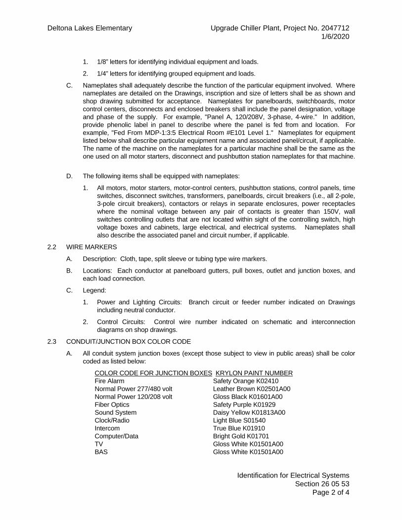
Deltona Lakes Elementary Upgrade Chiller Plant, Project No. 2047712
1/6/2020
Identification for Electrical Systems
Section 26 05 53
Page 2 of 4
1. 1/8” letters for identifying individual equipment and loads.
2. 1/4” letters for identifying grouped equipment and loads.
C. Nameplates shall adequately describe the function of the particular equipment involved. Where
nameplates are detailed on the Drawings, inscription and size of letters shall be as shown and
shop drawing submitted for acceptance. Nameplates for panelboards, switchboards, motor
control centers, disconnects and enclosed breakers shall include the panel designation, voltage
and phase of the supply. For example, "Panel A, 120/208V, 3-phase, 4-wire." In addition,
provide phenolic label in panel to describe where the panel is fed from and location. For
example, "Fed From MDP-1:3:5 Electrical Room #E101 Level 1." Nameplates for equipment
listed below shall describe particular equipment name and associated panel/circuit, if applicable.
The name of the machine on the nameplates for a particular machine shall be the same as the
one used on all motor starters, disconnect and pushbutton station nameplates for that machine.
D. The following items shall be equipped with nameplates:
1. All motors, motor starters, motor-control centers, pushbutton stations, control panels, time
switches, disconnect switches, transformers, panelboards, circuit breakers (i.e., all 2-pole,
3-pole circuit breakers), contactors or relays in separate enclosures, power receptacles
where the nominal voltage between any pair of contacts is greater than 150V, wall
switches controlling outlets that are not located within sight of the controlling switch, high
voltage boxes and cabinets, large electrical, and electrical systems. Nameplates shall
also describe the associated panel and circuit number, if applicable.
2.2 WIRE MARKERS
A. Description: Cloth, tape, split sleeve or tubing type wire markers.
B. Locations: Each conductor at panelboard gutters, pull boxes, outlet and junction boxes, and
each load connection.
C. Legend:
1. Power and Lighting Circuits: Branch circuit or feeder number indicated on Drawings
including neutral conductor.
2. Control Circuits: Control wire number indicated on schematic and interconnection
diagrams on shop drawings.
2.3 CONDUIT/JUNCTION BOX COLOR CODE
A. All conduit system junction boxes (except those subject to view in public areas) shall be color
coded as listed below:
COLOR CODE FOR JUNCTION BOXES KRYLON PAINT NUMBER
Fire Alarm Safety Orange K02410
Normal Power 277/480 volt Leather Brown K02501A00
Normal Power 120/208 volt Gloss Black K01601A00
Fiber Optics Safety Purple K01929
Sound System Daisy Yellow K01813A00
Clock/Radio Light Blue S01540
Intercom True Blue K01910
Computer/Data Bright Gold K01701
TV Gloss White K01501A00
BAS Gloss White K01501A00

Deltona Lakes Elementary Upgrade Chiller Plant, Project No. 2047712
1/6/2020
Identification for Electrical Systems
Section 26 05 53
Page 3 of 4
Security/CCTV Saddle Tan K03554
Telephone Safety Green K02012
Grounding Fluorescent Green K10339
B. Conduit (not subject to public view) longer than 20’ shall be painted with above color paint band
20’ on center. Paint band shall be 4" in length applied around entire conduit. Where conduits
are parallel and on conduit racking, the paint bands shall be evenly aligned. Paint shall be
neatly applied and uniform. Paint boxes and raceways prior to installation, or tape conduits and
surrounding surfaces to avoid overspray. Paint overspray shall be removed.
C. Junction boxes and conduits located in public areas (i.e. areas that can be seen by the public)
shall be painted to match surface attached to. Provide written request to A/E for interpretation
of public areas in question.
2.4 CONDUIT/JUNCTION BOX MARKER
A. All new and existing junction boxes/cover plates for power, lighting and systems (except those
installed in public areas) shall adequately describe its associated panel and circuit reference
number(s) within (i.e. ELRW-2, 4, 6), or systems within (i.e. fire alarm, intercom, etc.).
Identification shall be neatly written by means of black permanent marker. Paint one-half of
cover plate with appropriate color above, and one-half with associated panel/circuit or system
as described above. Junction box cover plates located in public areas shall be identified with
small phenolic labels securely attached. Label colors to be determined by A/E. Large
pull/junction boxes (8" x 8" or larger) shall be color identified by painting the corners of box
cover plate with specified colors at 45 degree angles; phenolic labels as specified herein.
B. Identify conduit not installed in public areas with corresponding panel/circuit numbers or
corresponding system type as described above. Spacing 20 ft. on center adjacent to color
identification bands.
2.5 UNDERGROUND WARNING TAPE
A. Description: Minimum 6” wide plastic tape, detectable type, with suitable warning legend
describing buried lines. Systems conduit shall have orange colored tape. Power/lighting
conduit shall have red colored tape.
PART 3 - EXECUTION
3.1 PREPARATION
A. Degrease and clean surfaces to receive nameplates and labels.
3.2 APPLICATION
A. Install nameplate parallel to equipment lines.
B. Secure nameplate to equipment front using stainless steel pop rivets.
C. Secure nameplate to inside surface of door on panelboard that is recessed in finished locations.
D. Nameplates installed inside on dead front cover shall be self-adhesive tape. Do not drill or
install screws in dead front.
E. Identify new and existing conduit, junction boxes, and outlet boxes using field painting.
F. Identify new underground conduit using underground warning tape. Install a minimum of one
tape per trench at 6” below finished grade. For trenches exceeding 24” in width, provide one
tape per 24” of trench width spaced evenly over trench width.

Deltona Lakes Elementary Upgrade Chiller Plant, Project No. 2047712
1/6/2020
Identification for Electrical Systems
Section 26 05 53
Page 4 of 4
G. Install wire markers at all new connections and terminations, and at existing connections and
terminations modified or altered.
END OF SECTION

Deltona Lakes Elementary Upgrade Chiller Plant, Project No. 2047712
1/6/2020
Tests and Performance Verification of Electrical System
Section 26 08 13
Page 1 of 4
SECTION 26 08 13
TESTS AND PERFORMANCE VERIFICATION OF ELECTRICAL SYSTEM
PART 1 - GENERAL
1.1 RELATED DOCUMENTS
A. Drawings and general provisions of the Contract, including General and Supplementary
Conditions and Division 01 Specification Sections, apply to this Section.
1.2 SUMMARY
A. This section pertains to the furnishing of all labor, materials, equipment and services necessary
to test and prove performance of the electrical system.
B. Operate system for a three day period. Do performance verification work as required to show
that the system is operating correctly in accordance with design. Supply instruments required to
read data. Adjust system to operate at the required performance levels.
PART 2 - PRODUCTS (Not Applicable)
PART 3 - EXECUTION
3.1 TESTS
A. System:
1. General: After installation of all conductors and before final acceptance, make required
tests to determine proper functioning of all circuits. Furnish all necessary instruments
required to make tests and correct any deficiencies found. Prior to energizing, circuits
shall be "rung-out" to verify opens, intentional and non-intentional grounds, continuity and
detect short circuits by accepted constant megger.
2. Procedure:
a) All wires in conduit that are shorted or unintentionally grounded shall be replaced.
b) Insulation resistance of all feeder conductors and all conductors AWG #1 and larger
shall be tested. This is to include all new conductors and/or all existing conductors
that are connected and/or extended. Each conductor shall have its insulation
resistance tested after the installation is completed and all splices, taps, and
connections are made, except connection to source and point of final termination at
distribution or utilization equipment.
c) Insulation resistance of conductors that are to operate at 600 volts or less shall be
tested by using AVO Biddle (or accepted equal) megger at not less than 1000 volts
dc. Resistance shall be measured from conductor to conduit (ground). Testing
methodology shall conform to short-time or spot-reading procedural
recommendations of AVO Biddle Instruments for specific megger being used.
Acceptable insulation resistance of conductors rated at 600 volts shall not be less
than 1 megohm.
d) Conductors that do not satisfy test requirements of paragraph c) above, shall be
removed, replaced, and testing repeated on new cable at no additional cost to the
Owner. All tests shall be performed by licensed electrician trained in the use of test
instruments. Contractor shall furnish all instruments and personnel required for
tests, shall tabulate readings observed and complete Conductor Insulation

Deltona Lakes Elementary Upgrade Chiller Plant, Project No. 2047712
1/6/2020
Tests and Performance Verification of Electrical System
Section 26 08 13
Page 2 of 4
Resistance Test form (see Section 26 01 00 Operation and Maintenance Manuals)
and submit five copies to Engineer for acceptance. Test shall be witnessed by
Owner’s Representative and Engineer (if so desired). Final acceptance data is to be
submitted in O & M Manual.
e) Test reports shall identify each feeder conductor tested, date, time and result of
test, weather conditions and range, test voltage, and serial number of the megger
instrument used. Any conductor or splice that is found defective shall be promptly
removed and replaced, and additional test shall be performed.
f) Observe all safety instructions set by testing equipment manufacturer. Application
of voltage testing involves risk of electric shock and sparking.
3. Take readings of voltage and amperage at building main disconnect switch and at main for
each panel, at primary and secondary side of each transformer, and at the end of the
longest branch circuit at each panel. The above readings shall be taken 1) "no load"
conditions and 2) "full load" conditions with all equipment using electricity. Tabulate
readings, complete Voltage and Amperage Readings (Tabulated Data) form (see Section
26 01 00 Operation and Maintenance Manuals) and submit five copies to the Engineer for
acceptance. Final accepted data is to be submitted in O & M Manual.
B. Motors:
1. Test run each motor via motor's control unit in both manual mode and automatic mode.
Verify proper operation, voltage and rotation.
C. Grounds:
1. Test each raceway for raceway continuity as called for in Section 26 05 26 Grounding and
Bonding.
2. Test each grounding system used in the project as called for in Section 26 05 26
Grounding and Bonding.
3. Submit Ground Test Information form (see Section 26 01 00 Operation and Maintenance
Manuals) for every grounding system in the project, including but not limited to, each
ground rod installation, each water pipe and ground installation (test water pipe to ground
and test water pipe to building service equipment), and each building steel ground
connection (test building steel to ground and test building steel to building service
equipment).
4. Grounding resistance shall be as called for in Section 26 05 26 Grounding and Bonding.
5. Testing shall be 3-point method in accordance with IEEE recommended practice.
6. Transformer grounding.
D. Communications:
1. See specific sections of these Specifications for further requirements.
E. UPS System:
1. See specific sections of these Specifications for further requirements.
F. IPS System:
1. See specific sections of these Specifications for further requirements.
G. Switchboard:

Deltona Lakes Elementary Upgrade Chiller Plant, Project No. 2047712
1/6/2020
Tests and Performance Verification of Electrical System
Section 26 08 13
Page 3 of 4
1. See specific sections of these Specifications for further requirements.
H. Service Ground Fault Protection System:
1. See specific sections of these Specifications for further requirements.
I. Ground Fault System:
1. The ground fault protection system shall be performance tested when first installed on site.
The test shall be conducted in accordance with instructions that shall be provided with the
equipment. A written record of this test shall be made and shall be provided to the
Authority Having Jurisdiction and to the Engineer of Record.
3.2 DATA PROCESSING
A. Testing Data.
1. Tabulate data for submission.
2. Submit data on 8 1/2" x 11" sheets with date and name of checker with one copy for each
O & M Manual.
3. Where specific performance verification information is called for in the Specifications, use
copies of the sheets provided for recording readings.
4. Data shall be submitted and accepted before Check Out Memos are signed or a request
for final inspection is made.
B. Equipment Check-Out:
1. At completion of construction after all performance verification and testing information has
been gathered, submitted, and approved, provide one copy of this information to the
Authorized Manufacturer's Representative of the equipment.
a) Manufacturer's Authorized Representative must be trained by the manufacturer and
authorized to inspect, adjust, test, and repair equipment.
2. Work required under this section shall include having the representative examine the
performance verification information, check the equipment in the field while it is in
operation, and sign a Check Out Memo form for a record. (See Section 26 01 00
Operation and Maintenance Manuals).
a) Check out of equipment is to include examining performance of equipment and
certifying equipment has been installed per manufacturer's recommendations, that
all necessary adjustments have been performed and that equipment is operating
properly.
3. Submit one copy (for each O & M Manual) of the memo on each major item of equipment.
Accepted memos shall be inserted in each O & M manual with the performance verification
information and submittal data. Memos shall be submitted and accepted before instruction
to Owner or a request for final inspection.
4. Items requiring Check Out Memos are all major items of equipment such as (but not
limited to):
a) Panels, distribution panels, switchboards.
b) Transformers.
c) UPS equipment.

Deltona Lakes Elementary Upgrade Chiller Plant, Project No. 2047712
1/6/2020
Tests and Performance Verification of Electrical System
Section 26 08 13
Page 4 of 4
d) Equipment/system installed per Systems sections.
e) Any other equipment noted to be checked-out by Engineer during construction.
f) Main Switchboard
g) Generators and all controls/annunciation
h) IPS Equipment
5. Do not submit Check Out Memo form at the time submittal brochures are submitted. This
form shall be completed and submitted before instruction in operation to Owner or a
request for final inspection.
END OF SECTION

Deltona Lakes Elementary Upgrade Chiller Plant, Project No. 2047712
1/6/2020
Cabinets and Enclosures
Section 26 27 16
Page 1 of 4
SECTION 26 27 16
CABINETS AND ENCLOSURES
PART 1 - GENERAL
1.1 RELATED DOCUMENTS
A. Drawings and general provisions of the Contract, including General and Supplementary
Conditions and Division 01 Specification Sections, apply to this Section.
1.2 SUMMARY
A. Provide and install all equipment, labor, material, accessories, and mounting hardware for a
complete and operating system for the following:
1. Hinged cover enclosures.
2. Cabinets.
B. Cabinets and enclosures are to include:
1. Terminal blocks,
2. Mounting panel,
3. Ground bus/bar, and
4. All accessories as required for a complete and operating system.
1.3 REFERENCES AND REGULATORY REQUIREMENTS
A. Conform to the requirements of the following:
1. NEMA 250 Enclosures for Electrical Equipment (1000 Volts Maximum)
2. NEMA ICS 4 Terminal Blocks
3. ANSI/NFPA 70 National Electrical Code
B. Furnish products listed and classified by Underwriters Laboratories as suitable for purpose
specified and shown.
1.4 SUBMITTALS
A. Submit Product Data: Provide manufacturer's standard data for enclosures and cabinets.
B. Submit Manufacturer's Instructions: Indicate application conditions and limitations of use
stipulated by product testing agency specified under “References and Regulatory
Requirements.” Include instructions for storage, handling, protection, examination, preparation,
installation, and starting of product.
C. Submit actual shop drawings on all cabinets and enclosures showing:
1. Covers.
2. Dimensions - inside and out.
3. Gauge of metal.
4. Manufacturer.
5. Terminal mounting plate, construction, etc.

Deltona Lakes Elementary Upgrade Chiller Plant, Project No. 2047712
1/6/2020
Cabinets and Enclosures
Section 26 27 16
Page 2 of 4
6. Ground bus/bar.
1.5 EXTRA MATERIALS
A. Provide two of each cabinet key.
PART 2 - PRODUCTS
2.1 GENERAL
A. Unless specifically called for otherwise on Contract Drawings, provide cabinets as specified
herein for terminal cabinets mounted indoors. Similarly, provide hinged cover enclosures as
specified herein for terminal cabinets mounted outdoors or in locations other then NEMA 1
locations. Also provide hinged cover enclosures for locations where size required is not
available in cabinet construction, or if specifically specified as enclosure in Contract Documents.
B. Size:
1. Dimensions of cabinets and enclosures shall meet the dimensions shown on Drawings,
dimensions required by NEC, or dimensions sized as required to facilitate all
equipment/connections involved installation, whichever is largest.
C. Provide metal barriers to separate compartments containing control wiring operating at less
than 50 volts from power wiring.
D. Provide accessory feet and/or mounting brackets for free-standing equipment.
E. Cabinets and enclosures installed outdoors shall be fully weatherproof and watertight.
2.2 HINGED COVER ENCLOSURES
A. Construction:
1. Interior Locations: NEMA Type 1 steel (unless otherwise noted).
2. Exterior Locations: NEMA Type 4X: 304 stainless steel.
B. Covers: Continuous hinge.
C. Enclosure Finish:
1. NEMA 1: manufacturer's standard metallic gray enamel over phosphatized surfaces.
2. NEMA 4X: 304 stainless steel.
D. Lock/Handle:
1. Provide/install key lock handle on all enclosures mounted in rooms/areas/spaces that are
not electrical rooms or mechanical rooms. Enclosures installed in electrical rooms need
not be and are not required to be lockable.
E. Interior Mounting Plate:
1. Each enclosure is to have interior mounting plate/panel for mounting terminal blocks and
electrical components.
2. Plate/panel is to be metal.
F. Ground Bus/Bar:
1. Each enclosure housing surge protective devices or other equipment shall have local
ground bar/bus installed. See "Local Ground Bus/Bar" included with this Section.
G. Manufacturers:
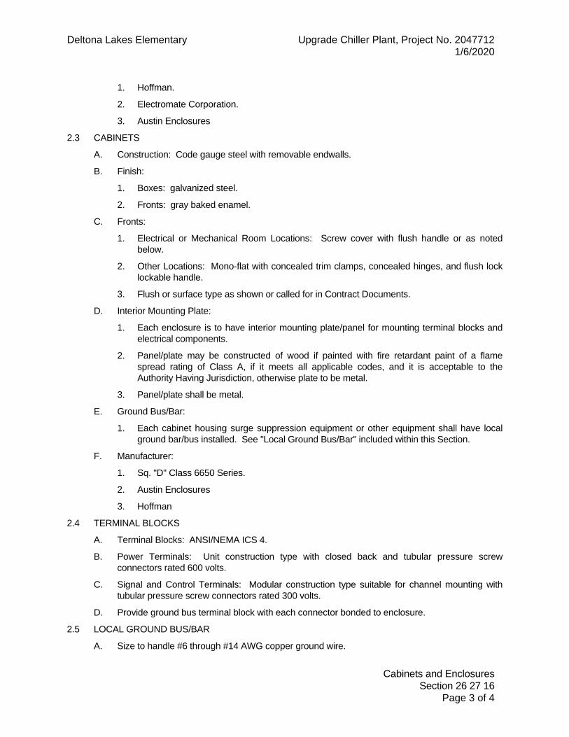
Deltona Lakes Elementary Upgrade Chiller Plant, Project No. 2047712
1/6/2020
Cabinets and Enclosures
Section 26 27 16
Page 3 of 4
1. Hoffman.
2. Electromate Corporation.
3. Austin Enclosures
2.3 CABINETS
A. Construction: Code gauge steel with removable endwalls.
B. Finish:
1. Boxes: galvanized steel.
2. Fronts: gray baked enamel.
C. Fronts:
1. Electrical or Mechanical Room Locations: Screw cover with flush handle or as noted
below.
2. Other Locations: Mono-flat with concealed trim clamps, concealed hinges, and flush lock
lockable handle.
3. Flush or surface type as shown or called for in Contract Documents.
D. Interior Mounting Plate:
1. Each enclosure is to have interior mounting plate/panel for mounting terminal blocks and
electrical components.
2. Panel/plate may be constructed of wood if painted with fire retardant paint of a flame
spread rating of Class A, if it meets all applicable codes, and it is acceptable to the
Authority Having Jurisdiction, otherwise plate to be metal.
3. Panel/plate shall be metal.
E. Ground Bus/Bar:
1. Each cabinet housing surge suppression equipment or other equipment shall have local
ground bar/bus installed. See "Local Ground Bus/Bar" included within this Section.
F. Manufacturer:
1. Sq. "D" Class 6650 Series.
2. Austin Enclosures
3. Hoffman
2.4 TERMINAL BLOCKS
A. Terminal Blocks: ANSI/NEMA ICS 4.
B. Power Terminals: Unit construction type with closed back and tubular pressure screw
connectors rated 600 volts.
C. Signal and Control Terminals: Modular construction type suitable for channel mounting with
tubular pressure screw connectors rated 300 volts.
D. Provide ground bus terminal block with each connector bonded to enclosure.
2.5 LOCAL GROUND BUS/BAR
A. Size to handle #6 through #14 AWG copper ground wire.

Deltona Lakes Elementary Upgrade Chiller Plant, Project No. 2047712
1/6/2020
Cabinets and Enclosures
Section 26 27 16
Page 4 of 4
B. Length as required for circuits.
C. Manufacturer:
1. Sq. "D" #PK***GTA Series.
PART 3 - EXECUTION
3.1 EXAMINATION
A. Verify that surfaces are ready to receive work.
3.2 INSTALLATION
A. Install Products in accordance with manufacturer's instructions.
B. Install enclosures and cabinets plumb. Anchor securely to wall and structural supports at each
corner.
C. Install cabinet fronts plumb.
D. Install per NEC and as required for proper clearance. Coordinate with panels.
E. Provide and install terminal cabinets as shown on Drawings or as required by the NEC.
F. Provide and install terminal cabinets wherever required for a complete and operating distribution
system whether shown on Drawings or not.
G. Install local ground bus/bar in each terminal cabinet/enclosure that houses surge protective
devices or other equipment and bond to cabinet enclosure via mounting screws or #6 AWG
copper ground wire.
H. Ground local ground bus to systems ground bus/bar with minimum #6 AWG copper ground
wire. Increase size if so required on drawings.
I. Install enclosures.
END OF SECTION

Deltona Lakes Elementary Upgrade Chiller Plant, Project No. 2047712
1/6/2020
Wiring Devices
Section 26 27 26
Page 1 of 6
SECTION 26 27 26
WIRING DEVICES
PART 1 – GENERAL
1.1 RELATED DOCUMENTS
A. Drawings and general provisions of the Contract, including General and Supplementary
Conditions and other Division 01 Specification Sections apply to this Section.
1.2 SUMMARY
A. Provide and install all equipment, labor, material, accessories, and mounting hardware for a
complete and operating system for the following:
1. Wall switches.
2. Receptacles.
3. Device plates and decorative box covers.
1.3 REFERENCES
A. NEMA WD 1 General Requirements for Wiring Devices
B. NEMA WD 6 Wiring Devices Dimensional Specifications
1.4 REGULATORY REQUIREMENTS
A. Conform to requirements of ANSI/NFPA 70.
B. Furnish products listed and classified by Underwriters Laboratories as suitable for purpose
specified and shown.
1.5 SUBMITTALS
A. Submit Product Data: Provide manufacturer's catalog information showing dimensions, colors,
and configurations.
1. Submit product data on all types of wiring devices including plates and engraving.
B. Submit Manufacturer's Instructions:
1. Indicate application conditions and limitations of use stipulated by product testing agency
specified under regulatory requirements.
2. Include instructions for storage, handling, protection, examination, preparation, operation
and installation of product.
1.6 QUALIFICATIONS
A. Manufacturer: Company specializing in manufacturing products specified in this Section with
minimum five years experience.
1.7 EXTRA MATERIALS
A. Provide a minimum of two screwdrivers of each type of tamper proof screw used on project.
B. Turn over to Owner and submit Spare Parts/Maintenance Stock Certification. (See Section 26
01 00 Operation and Maintenance Manual).
PART 2 - PRODUCTS
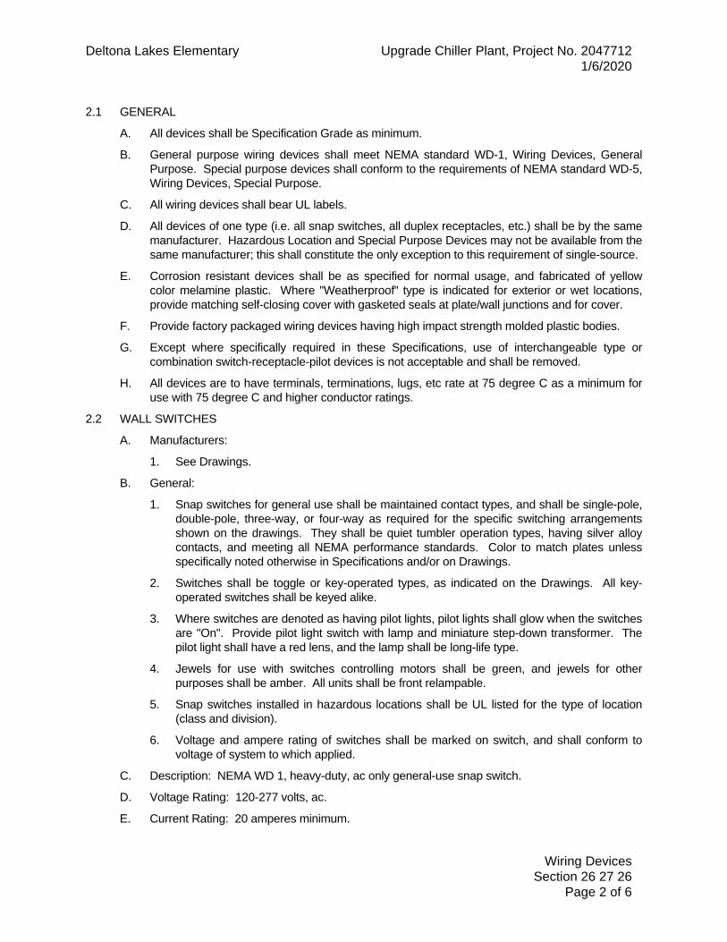
Deltona Lakes Elementary Upgrade Chiller Plant, Project No. 2047712
1/6/2020
Wiring Devices
Section 26 27 26
Page 2 of 6
2.1 GENERAL
A. All devices shall be Specification Grade as minimum.
B. General purpose wiring devices shall meet NEMA standard WD-1, Wiring Devices, General
Purpose. Special purpose devices shall conform to the requirements of NEMA standard WD-5,
Wiring Devices, Special Purpose.
C. All wiring devices shall bear UL labels.
D. All devices of one type (i.e. all snap switches, all duplex receptacles, etc.) shall be by the same
manufacturer. Hazardous Location and Special Purpose Devices may not be available from the
same manufacturer; this shall constitute the only exception to this requirement of single-source.
E. Corrosion resistant devices shall be as specified for normal usage, and fabricated of yellow
color melamine plastic. Where "Weatherproof" type is indicated for exterior or wet locations,
provide matching self-closing cover with gasketed seals at plate/wall junctions and for cover.
F. Provide factory packaged wiring devices having high impact strength molded plastic bodies.
G. Except where specifically required in these Specifications, use of interchangeable type or
combination switch-receptacle-pilot devices is not acceptable and shall be removed.
H. All devices are to have terminals, terminations, lugs, etc rate at 75 degree C as a minimum for
use with 75 degree C and higher conductor ratings.
2.2 WALL SWITCHES
A. Manufacturers:
1. See Drawings.
B. General:
1. Snap switches for general use shall be maintained contact types, and shall be single-pole,
double-pole, three-way, or four-way as required for the specific switching arrangements
shown on the drawings. They shall be quiet tumbler operation types, having silver alloy
contacts, and meeting all NEMA performance standards. Color to match plates unless
specifically noted otherwise in Specifications and/or on Drawings.
2. Switches shall be toggle or key-operated types, as indicated on the Drawings. All key-
operated switches shall be keyed alike.
3. Where switches are denoted as having pilot lights, pilot lights shall glow when the switches
are "On". Provide pilot light switch with lamp and miniature step-down transformer. The
pilot light shall have a red lens, and the lamp shall be long-life type.
4. Jewels for use with switches controlling motors shall be green, and jewels for other
purposes shall be amber. All units shall be front relampable.
5. Snap switches installed in hazardous locations shall be UL listed for the type of location
(class and division).
6. Voltage and ampere rating of switches shall be marked on switch, and shall conform to
voltage of system to which applied.
C. Description: NEMA WD 1, heavy-duty, ac only general-use snap switch.
D. Voltage Rating: 120-277 volts, ac.
E. Current Rating: 20 amperes minimum.

Deltona Lakes Elementary Upgrade Chiller Plant, Project No. 2047712
1/6/2020
Wiring Devices
Section 26 27 26
Page 3 of 6
F. Ratings: Match branch circuit and load characteristics.
2.3 RECEPTACLES
A. General:
1. All receptacles shall be of standard NEMA configuration, as indicated on the Drawings,
and shall comply with the respective ANSI C73 series standard for the NEMA
configuration. Color to match plates unless specifically noted otherwise in specifications
and/or on drawings.
2. Duplex receptacles shall have integral UL listed self-grounding clips. Similar, single
receptacles shall be provided for plug-in connections of Industrial Fluorescent light fixtures
on the same switching circuit. Receptacle face to be impact resistant nylon.
3. Weatherproof duplex receptacles shall be provided in all exterior locations, and shall be
ground fault circuit interrupting (GFCI) types, with weatherproof cover plates allowing use
of receptacle with cover in closed position.
4. Special purpose receptacles for specific equipment shall be grounding types, having the
number of poles, voltage and ampere ratings, and NEMA configurations required by the
equipment. For each special purpose receptacle, provide an identical mating plug
equipped with cord grip, secured to cord.
5. Duplex receptacles shall have back and side wired screw pressure terminals.
B. Description: NEMA WD 1; heavy-duty general use receptacle.
C. Configuration: NEMA WD 6; heavy-duty, general use type as specified and indicated.
D. Convenience Receptacle: Type 5-20.
E. GFCI Receptacle: Convenience receptacle with integral ground fault circuit interrupter to meet
regulatory requirements.
F. Manufacturers:
1. See Drawings.
2.4 COVER PLATES
A. All wiring devices shall be provided with standard size one-piece cover plates of suitable
configuration for the number and type of devices to be covered.
B. Metallic cover plates shall be used in interior spaces, except as noted below, and shall be
fabricated of corrosion-resistant #302 stainless steel having a nominal thickness of .04" and a
brushed finish. Screws securing the plates shall have flush (when installed) heads with finish to
match plates. Metallic cover plates shall meet all requirements of the National Electrical Code
and Federal Specifications.
C. Cover plates for switches located in corrosive atmospheres (where vapor proof is not indicated)
shall be equal to Hubbell #17CM81/#17CM82/#17CM83/#17CM84 one-piece neoprene with
matching presswitch.
D. Cover plates for exterior receptacles shall be gasketed covers with hinge allowing plug and cord
to be plugged in and activated with cover closed..
E. Cover plate engraving, where required, shall be accomplished by cover plate manufacturer in
accordance with instructions given on the Drawings. Metallic plates shall be engraved with
black fill.

Deltona Lakes Elementary Upgrade Chiller Plant, Project No. 2047712
1/6/2020
Wiring Devices
Section 26 27 26
Page 4 of 6
F. Unless specifically noted otherwise in Specifications or on Drawings, all outlets for telephone
and other communications and data systems shall be provided with standard size one-piece
cover plates having a minimum 3/4” diameter bushed hole in the center unless specifically
noted otherwise in Specifications and/or on Drawings. Where telephone conductors are
installed, plates shall contain telephone type, polarized plug-in receptacles.
2.5 COLOR
A. Wiring devices connected to normal power and located in unfinished spaces shall be grey color.
Devices connected to normal power and located in finished interior spaces shall be of color
selected by Architect from the following list of standard colors: ivory, beige, gray, white, brown,
black.
B. Cover plates for devices connected to normal power and located in finished interior spaces shall
be of color selected by Architect from the above list of standard colors or #302 stainless steel.
C. All devices and coverplates in paneled walls shall have finish to match paneling.
D. Contractor shall modify any given catalog numbers as required to procure devices and plates of
the proper color.
PART 3- EXECUTION
3.1 EXAMINATION
A. Verify conditions under provisions of Division 01 General Requirements and any other
applicable supplemental requirements/conditions.
B. Verify outlet boxes are installed at proper height.
C. Verify wall openings are neatly cut and will be completely covered by wall plates.
D. Verify floor boxes are adjusted properly.
E. Verify branch circuit wiring installation is completed, tested, and ready for connection to wiring
devices.
3.2 PREPARATION
A. Provide extension rings to bring outlet boxes flush with finished surface.
B. Clean debris from outlet boxes.
3.3 INSTALLATION
A. Install products in accordance with manufacturer's instructions.
B. Install devices plumb and level.
C. Install switches with OFF position down.
D. Install wall dimmers to achieve full rating specified and indicated after derating for ganging as
instructed by manufacturer.
E. Do not share neutral conductor on load side of dimmers.
F. Install receptacles with grounding pole on bottom.
G. Install decorative plates on switch, receptacle, and blank outlets in finished areas.
H. Electrical boxes shall be cleaned and completely free of any debris, dust, etc. prior to the
installation of wiring devices.

Deltona Lakes Elementary Upgrade Chiller Plant, Project No. 2047712
1/6/2020
Wiring Devices
Section 26 27 26
Page 5 of 6
I. Where two or more switches or receptacles are to be installed adjacent to one another, provide
a multi-gang box and combination multi-gang coverplate. Provide proper NEC barriers in boxes
which serve devices for both the Normal and Emergency Systems.
J. Provide device coverplates for every device installed. Cover plates shall be installed so that
they appear straight with no gaps between plate edges and the wall. Maintain vertical and
horizontal to within 1/16 of an inch.
K. In finished areas provide same type of plate for all surface mounted devices as for recessed
mounted devices.
L. In any room where new and existing construction is present, all receptacles, switches, and
coverplates which are existing to remain shall be changed as required to match new work.
M. Wiring devices shall not be installed in exposed masonry until cleaning of masonry with acids
has been completed.
N. All receptacles and switches shall be grounded by means of a ground wire from device ground
screw to outlet box screw and branch circuit ground conductor. Strap alone will not constitute
an acceptable ground.
O. All wiring devices, relays, contactors, pushbuttons, selector switches, pilot lights, etc. shall be
installed in approved enclosures rated for the appropriate NEMA classified environment.
P. All devices shall be installed so that only one wire is connected to each terminal.
Q. Once construction is substantially completed, replace all damaged, burned, or scorched wiring
devices.
R. Receptacles shown to be floor mounted shall be installed in floor boxes (with coverplates) which
are approved for this use.
S. Connect wiring devices by wrapping conductor around screw terminal.
T. Install galvanized steel plates on outlet boxes and junction boxes in unfinished areas, above
accessible ceilings, and on surface mounted outlets.
U. Install protective rings and split nozzle on active flush cover service fittings.
V. Install local room area wall switches at door locations on the lock side of the door approximately
4” from the jamb. Where locations shown on the Drawings are in question, provide written
request for information to A/E prior to rough-in.
3.4 NEUTRAL CONDUCTOR CONNECTIONS
A. Each receptacle’s "in" and "out" phase and neutral conductors shall have an additional
conductor for connection to device. The practice of "looping" conductors through receptacle
boxes shall not be acceptable.
3.5 INTERFACE WITH OTHER PRODUCTS
A. Coordinate locations of outlet boxes provided under other Sections of these Specifications to
obtain mounting heights specified and indicated on Drawings.
3.6 FIELD QUALITY CONTROL
A. Inspect each wiring device for defects.
B. Operate each wall switch with circuit energized and verify proper operation.
C. Verify that each receptacle device is energized.

Deltona Lakes Elementary Upgrade Chiller Plant, Project No. 2047712
1/6/2020
Wiring Devices
Section 26 27 26
Page 6 of 6
D. Test each receptacle device for proper polarity.
E. Test each GFCI receptacle device for proper operation.
3.7 ADJUSTING
A. Adjust devices and wall plates to be flush and level.
END OF SECTION

Deltona Lakes Elementary Upgrade Chiller Plant, Project No. 2047712
1/6/2020
Enclosed Disconnect Switches
26 28 19
Page 1 of 3
SECTION 26 28 19
ENCLOSED DISCONNECT SWITCHES
PART 1 - GENERAL
1.1 RELATED DOCUMENTS
A. Drawings and general provisions of the Contract, including General and Supplementary
Conditions and Division 01 Specification Sections, apply to this Section.
1.2 DESCRIPTION
A. Provide all labor, materials, and equipment necessary to properly install switches as shown on
the Drawings and as required by codes.
B. Coordinate with Division 23 Contractor and Specifications as to who is to provide disconnect
switches for mechanical equipment. Provide all disconnect switches not being provided by
Division 23 Contractor.
1.3 PRODUCT DELIVERY, STORAGE, AND HANDLING
A. Deliver switches in factory wrapped packaging to the site. Handle switches carefully to prevent
damage. Store in a clean, dry space protected from dirt, water, and physical damage. Do not
install damaged switches.
1.4 QUALITY ASSURANCE
A. The manufacturer of switches shall be the same as that of the panelboards.
1.5 SUBMITTALS
A. Submit catalog cut sheet on each type of disconnect switch to be used on this project. Submit
catalog cut sheet on enclosure locks to be used on this project.
PART 2 - PRODUCTS
2.1 CONSTRUCTION
A. Switches shall be heavy duty types with visible, quick-make, quick-break blades.
B. Units for 2-speed motors shall be 6-pole in a single enclosure. Use of two 3-pole units will not
be acceptable.
C. Provide ground bus, and where required a solid neutral bus.
D. Switches shall be fusible or nonfusible as denoted on the Drawings or as required by the
equipment served from the switch. Fusible switches shall have rejection type fuse holders.
E. Terminal lugs shall be rated for 75 degrees Centigrade.
F. Enclosures, unless otherwise noted, shall be NEMA 1 for indoor locations and NEMA 4X
stainless steel for outdoor locations as a minimum. All switches mounted outdoors including
those noted to be NEMA 3R on drawings shall be heavy duty type 4X, watertight, corrosion
resistant
G. The enclosure shall be interlocked with the switch handle such that the enclosure door or cover
cannot be opened with the switch in the "ON" position. The switch handle shall be capable of
being padlocked in the "OFF" position but not in the "ON" position.
H. Finish for NEMA I units shall be standard baked gray enamel finish over a rust inhibiting

Deltona Lakes Elementary Upgrade Chiller Plant, Project No. 2047712
1/6/2020
Enclosed Disconnect Switches
26 28 19
Page 2 of 3
phosphate primer.
I. Each disconnect switch shall be provided with a Homac #ELB-2 or similar enclosure lock.
Homac #ELB-2 is available from Graybar Electric.
J. Disconnect switches installed between any variable speed drive type of unit (VFD, AFD, USD,
etc.) and its respective motor(s), shall have auxiliary break before break (open) interlock control
contact.
K. Disconnect switches installed to disconnect HVAC equipment are to be fusible type with fuses
as recommended by HVAC manufacturer.
2.2 RATING
A. The size, number of poles, and fusing for each switch shall be as denoted on the Drawings. As
a minimum, no less than one pole for each ungrounded conductor shall be provided. Switches
shall be rated 250 VAC or 600 VAC as required by the circuit to which it is connected.
B. Switches serving motors with more than one set of windings shall have the number of poles
necessary to disconnect all conductors to all windings in a single switch. Switches serving
motor loads shall be horsepower rated of sufficient size to handle the load.
2.3 SERVICE ENTRANCE EQUIPMENT
A. Switches used as service entrance equipment shall be listed and labeled by UL for use as
service equipment.
2.4 KITCHEN EQUIPMENT
A. All switches in kitchen areas, wet areas, etc. to be NEMA 4 stainless steel.
2.5 ENCLOSED CIRCUIT BREAKERS
A. Molded Case Circuit Breakers: NEMA AB1, plug-on type for 250V or less, bolt-on type for over
250V, thermal magnetic trip circuit breakers, with common trip handle for all poles. Provide
circuit breakers UL listed as Type SWD for lighting circuits. Breakers shall be HID rated.
Provide UL Class A ground fault interrupter circuit breakers where scheduled. Do not use
tandem circuit breakers.
B. Thermal-magnetic, molded case, with inverse time-current overload and instantaneous
magnetic tripping, unless otherwise shown. Breakers shall be calibrated for 40 degrees C or
shall be ambient compensating.
PART 3 - EXECUTION
3.1 INSTALLATION
A. Install all switches in accordance with the manufacturer's written instructions, NECA National
Electrical Installation Standards, the applicable requirements of the NEC, and recognized
industry practice.
B. All switches shall be firmly anchored to walls and supporting structures (where used) using
appropriate installation. Switches shall be installed with the turning axis of their handles
approximately 5'-0" above finished floor unless otherwise indicated. Provide rigid steel
(galvanized for exterior use) mounting stands, brackets, plates, hardware, and accessories for a
complete installation.
C. Switches shall be mounted in accessible locations chosen where the passageway to the switch
is not likely to become obstructed. Where a switch serves as the disconnecting means for a
load, the switch shall be located as close as practical to the load with the switch handle within

Deltona Lakes Elementary Upgrade Chiller Plant, Project No. 2047712
1/6/2020
Enclosed Disconnect Switches
26 28 19
Page 3 of 3
sight of the load.
D. Provide and install lugs on disconnect switch as required to accept conductors called for on
Drawings.
E. Disconnect switches shall not be mounted on equipment unless specifically noted or required,
and meet all applicable codes, etc. If switches are noted or required to be mounted on
equipment, they shall have vibrator clips on fuses and be connected to conduit system with
liquid tight flexible conduit.
F. Provide and install enclosure lock on each disconnect switch. Enclosure lock bolt shall be
tightened firmly but not tight enough to break bolt.
G. Coordinate all requirements for controls between variable speed drive unit and its respective
motor with drive specification, manufacturer, provider and installer. Provide auxiliary contacts,
relays, etc. as required.
END OF SECTION

Deltona Lakes Elementary Upgrade Chiller Plant, Project No. 2047712
1/6/2020
Motor Control
Section 26 29 13
Page 1 of 3
SECTION 26 29 13
MOTOR CONTROL
PART 1 - GENERAL
1.1 RELATED DOCUMENTS
A. Drawings and general provisions of the Contract, including General and Supplementary
Conditions and Division 01 Specification Sections, apply to this Section.
1.2 SUMMARY
A. This Section of the Specification covers factory-assembled, metal-enclosed motor control units
for distribution and control of power from incoming line terminals to outgoing feeder terminals,
installed and tested in place.
B. Motor control units shall include all protective devices and equipment as listed on drawings or
as included in these specifications, with necessary interconnections, instrumentation, and
control wiring.
1.3 FURNISHING OF EQUIPMENT
A. Unless specifically noted otherwise, automatic motor starters for all equipment requiring them
shall be furnished under the section or division where equipment is specified, and shall be
installed under this Section of the Specifications.
B. Unless specifically noted otherwise, manual motor starters shall be furnished and installed
under this Section of the Specifications.
C. Disconnect switches for 120V fractional hp exhaust fans to be provided by Division 23
Contractor at exhaust fan. Any other required disconnect switch to be provided and installed by
Division (26 ) Contractor.
D. Provide and install 75 degree rated lugs on all non-unitary mechanical equipment such as
pumps, air handling units and individual motor units/equipment. Coordinate with Division 23
Contractor prior to bid.
1.4 CONTROL ITEMS
A. Unless specifically noted otherwise, all control, alarm and interlock wiring required for proper
operation of equipment furnished by any other contractor, and the required raceways, shall be
furnished and installed under the division where the equipment is specified.
B. Where required by Electrical Drawings, Division 23 Specifications, and/or Mechanical Drawings
this Contractor shall connect power feeder to mechanical equipment via control devices
furnished by Division 23 Contractor; (i.e. starters, line voltage, t'stats, line voltage switch, control
relays, etc.).
C. Provide and install power circuits to all control devices requiring them (i.e. 120V dampers,
control panels, control devices, etc.) whether shown on Drawings or not. Coordinate
requirements of all Divisions and/or Sections of these Specifications prior to bid.
1.5 SUBMITTALS
A. Shop Drawings and Product Data:
1. Shop Drawings, Individually mounted AC Manual Starter:
a) Shop Drawings shall clearly indicate:

Deltona Lakes Elementary Upgrade Chiller Plant, Project No. 2047712
1/6/2020
Motor Control
Section 26 29 13
Page 2 of 3
1. Frame sizes and Interrupting capacity of manual starter and/or disconnect unit.
2. Horsepower rating at rated voltage of manual starter and/or disconnect unit.
3. Electrical ratings.
4. Single line diagram for power and control connections with numbered terminals
and all required accessories.
5. All required accessories.
PART 2 - PRODUCTS
2.1 MANUFACTURERS
A. Basis of Design:
1. Square D
B. Accepted Substitutions:
1. General Electric
2. Siemens/ITE
2.2 GENERAL
A. Motor starters shall be manual, magnetic, or combination type as denoted on the Drawings.
B. Pilot lights shall have long-life lamps rated 7500 hours minimum.
C. Enclosures shall be NEMA 1 for indoor locations and NEMA 4SS for outdoor or wet locations
except where indicated as NEMA 4.
D. Multi-speed or stop type controllers shall have thermal overload relays in each ungrounded
conductor for each speed or step.
E. Where multi-speed motors are scheduled on the Drawings, the motor controls shall be
compatible with the type motor and have adjustable time deceleration for transition from high to
low speeds.
2.3 INDIVIDUALLY MOUNTED AC MANUAL STARTERS
A. Where manual motor starter switch is called for on Drawings, it shall be a combination across-
the-line manual type starter with overloads and disconnect rated in accordance with NEMA
standards, sizes and horsepower rating. Final rating of overloads shall be field set and
recorded. Unit shall be mounted on NEMA 1 enclosures, unless otherwise noted.
B. Manual motor starter switch shall include green "run" pilot light, and shall be surface or flush
mounted as noted on Drawings.
PART 3 - EXECUTION
3.1 INSPECTION
A. Examine area to receive motor-control units to assure adequate clearance for motor control unit
installation.
B. Start work only after unsatisfactory conditions are corrected.
3.2 INSTALLATION
A. Install motor control units in accordance with manufacturer's written instructions and NEC.

Deltona Lakes Elementary Upgrade Chiller Plant, Project No. 2047712
1/6/2020
Motor Control
Section 26 29 13
Page 3 of 3
B. All starters and their respective enclosures shall be firmly anchored to walls and supporting
structures (where used) using appropriate hardware. Provide supporting (unistrut type)
channels on walls constructed of gypsum board or where otherwise necessary to provide a
mechanically secure and permanent installation. Starters shall be installed with their turning
axis of their handles approximately 5'-0" above finished floor. Provide rigid steel (galvanized for
exterior use) mounting stands, brackets, plates, hardware, and accessories for a complete
installation.
C. Starters shall be mounted where shown on the drawings. Where the starter also provides the
code-required disconnecting means for a load, the starter shall be located within sight of the
load and as close as feasible.
D. Provide fusing for all fusible switches.
E. Provide properly sized heater elements for every starter overload relay. The element shall be
sized using the nameplate full load running current of the actual equipment supplied to the job.
F. Provide a heater element selection chart on the inside of each starter door.
G. Provide spare pilot light lamps to the Owner. Provide two of each type and size load.
H. Provide nameplate for each control unit.
I. Coordinate conductor terminations on all equipment connections. Replace all 60 degree
lugs/connections with 75 degree lug/connection.
3.3 ADJUSTMENT AND CLEANING
A. Adjust operating mechanisms for free mechanical movement.
B. Touch-up scratched or marred surfaces to match original finish.
C. Tighten bus connections and mechanical fasteners.
END OF SECTION


![1 1-800-503-6769-800-503-6769 FALL CLASSES FORMING P^]g^l ...€¦ · Marc Shepard, MD at Accelovance 202-223-6777. F43=4B30H k ! ! $ k 4G?A4BB k " =PcX^];>B 0=64;4B 1[PRZ^dc 2dcb](https://img.pdfslide.us/doc/110x75/6074ab349913d56eab05b404/1-1-800-503-6769-800-503-6769-fall-classes-forming-pgl-marc-shepard-md-at.jpg)