Embed Size (px)
Citation preview
! 1! 1 4 - 0 0 0 2 R e v. H , S e p t 2 0 1 3
Technique Guide
www.aptismedical.com
502.523.6738
The SchekerDistal Radio-Ulnar Joint
Prosthesis
TABLE OF CONTENTS
General Precautions! ! ! ! ! ! ! ! ! 2Indications for use! ! ! ! ! ! ! ! ! ! 2Contraindications! ! ! ! ! ! ! ! ! ! 2Patient Counseling/Warnings!! ! ! ! ! ! ! 3Surgical Procedures! ! ! ! ! ! ! ! ! 3! ! ! ! ! ! ! ! !Distal Radio-Ulnar Joint Prosthesis and Instrumentation ! ! 4-5Templating ! ! ! ! ! ! ! ! ! ! ! 6-7
Surgical Procedure_______________________________________! Patient Preparation! ! ! ! ! ! ! ! ! 8 !! Incision / Dissection! ! ! ! ! ! ! ! ! 8-9! Ulna Head Excision! ! ! ! ! ! ! ! ! 10! ! Radial Plate Trial Positioning! ! ! ! ! ! 11-13!! Radial Plate Introduction and Fixation! ! ! ! ! 14! !! Locking Plate Surgical Technique Addendum! ! ! ! 15-17! Distal Ulnar Resection! ! ! ! ! ! ! ! 18-19!! Preparation for the Ulnar Stem ! ! ! ! ! ! ! 20! Ulnar Stem Optional Lengths and Diameters! ! ! ! 21! Introduction of the Ulnar Stem! ! ! ! ! ! 22! UHMWP Ball Placement ! ! ! ! ! ! ! ! 23! Radial Plate Cover Placement and Fixation!! ! ! ! 23! Range of Motion Evaluation! ! ! ! ! ! ! 24! ! ! ! ! ! ! ! ! Closure ! ! ! ! ! ! ! ! ! ! 24!!
Post-operative Management ! ! ! ! ! ! ! ! 25
Positioning Reference Guide! ! ! ! ! ! 26
1
GENERAL PRECAUTIONSAll surgical procedures and techniques are the responsibility of the medical professional. The surgeon, based on personal medical training and experience, must evaluate the procedure for appropriateness. No one technique is suitable for all patients.
INDICATIONS FOR USEAptis Medical Distal Radio Ulnar Joint implant is intended for replacement of the distal radioulnar joint following ulnar head resection arthroplasty:
! Replacement of the distal radio-ulnar head for rheumatoid, degenerative, or post-! traumatic arthritis presenting with the following findings:
• Pain and weakness of the wrist joint not improved by non-operative treatment• Instability of the ulna head with radiographic evidence of dislocation or erosive
changes of the distal radio-ulnar joint• Failed ulna head resection; e.g. Darrach resection • !Primary replacement after fracture of the ulna head or neck.• Revision following failed ulna head arthroplasty.
CONTRAINDICATIONSPatients should be made aware of the increased potential for device failure when excessive demands are made upon it. Strenuous loading, excessive mobility, and articular instability all may lead to accelerated wear and eventual failure by loosening, fracture, or dislocation of the device.Patients should be cautioned to not lift loads of 20 lbs or greater. Doing so may result in device failure. Patients receiving an extended stem should be cautioned not to lift loads of 5 lbs or greater. Doing so may result in device failure.See product insert for additional information including adverse effects, cautions and warnings.
2
PATIENT COUNSELING INFORMATION (SEE ALSO WARNINGS) In addition to the patient related information contained in the Warnings and Adverse Events sections, the following information should be conveyed to the patient:
While the expected life of total joint replacement components is difficult to estimate, it is finite. These components are made of foreign materials, which are placed within the body for the potential restoration of mobility or reduction of pain. However, due to the many biological, mechanical and physiochemical factors which affect these devices, the components cannot be expected to withstand the activity level and loads of normal healthy bone for an unlimited period of time.
Adverse effects of this device may necessitate reoperation, revision, or fusion of the involved joint.
SURGICAL PROCEDURES A manual is available describing detailed surgical procedures for use of these implant devices. It is the responsibility of the surgeon to be familiar with the procedure before use of these products. In addition, it is the responsibility of the surgeon to be familiar with relevant publications and consult with experienced associates regarding the implant procedures before use.
3
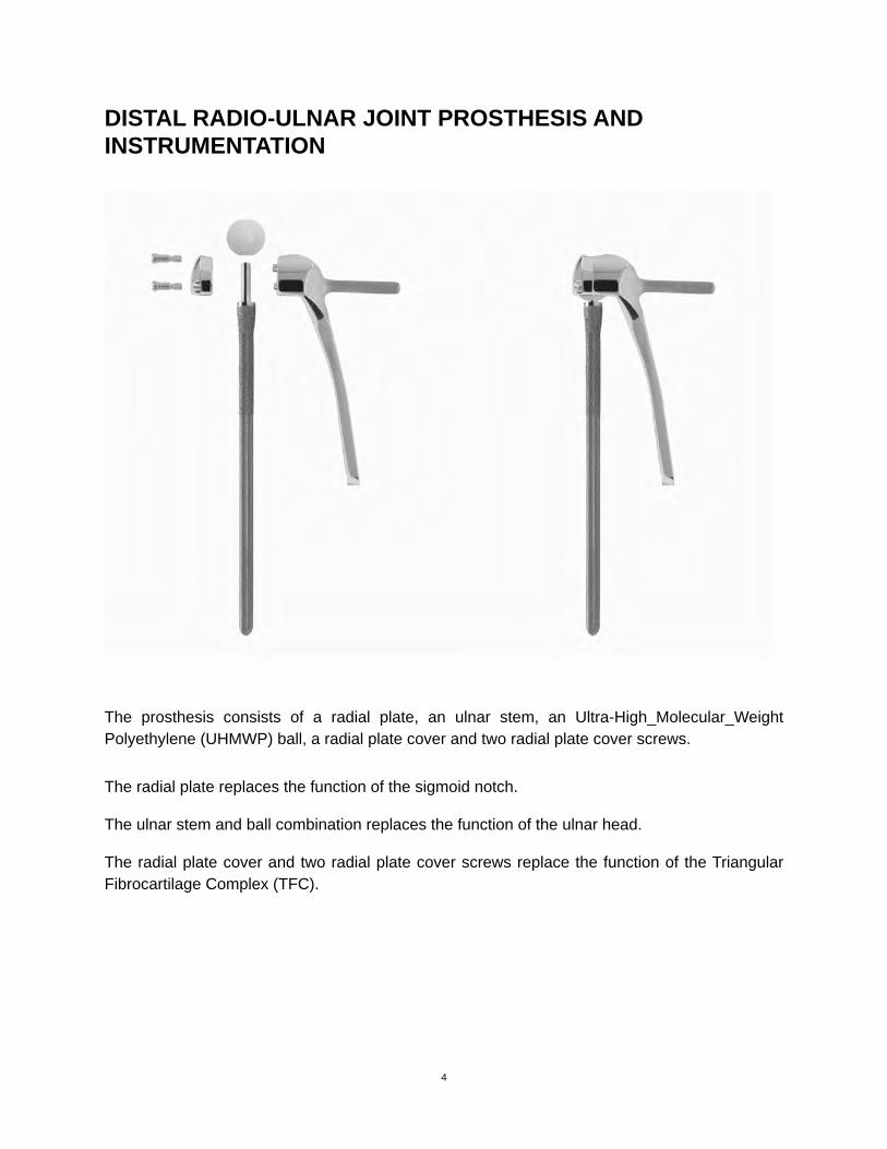
DISTAL RADIO-ULNAR JOINT PROSTHESIS AND INSTRUMENTATION
!
The prosthesis consists of a radial plate, an ulnar stem, an Ultra-High_Molecular_Weight Polyethylene (UHMWP) ball, a radial plate cover and two radial plate cover screws.
The radial plate replaces the function of the sigmoid notch.
The ulnar stem and ball combination replaces the function of the ulnar head.
The radial plate cover and two radial plate cover screws replace the function of the Triangular Fibrocartilage Complex (TFC).
4
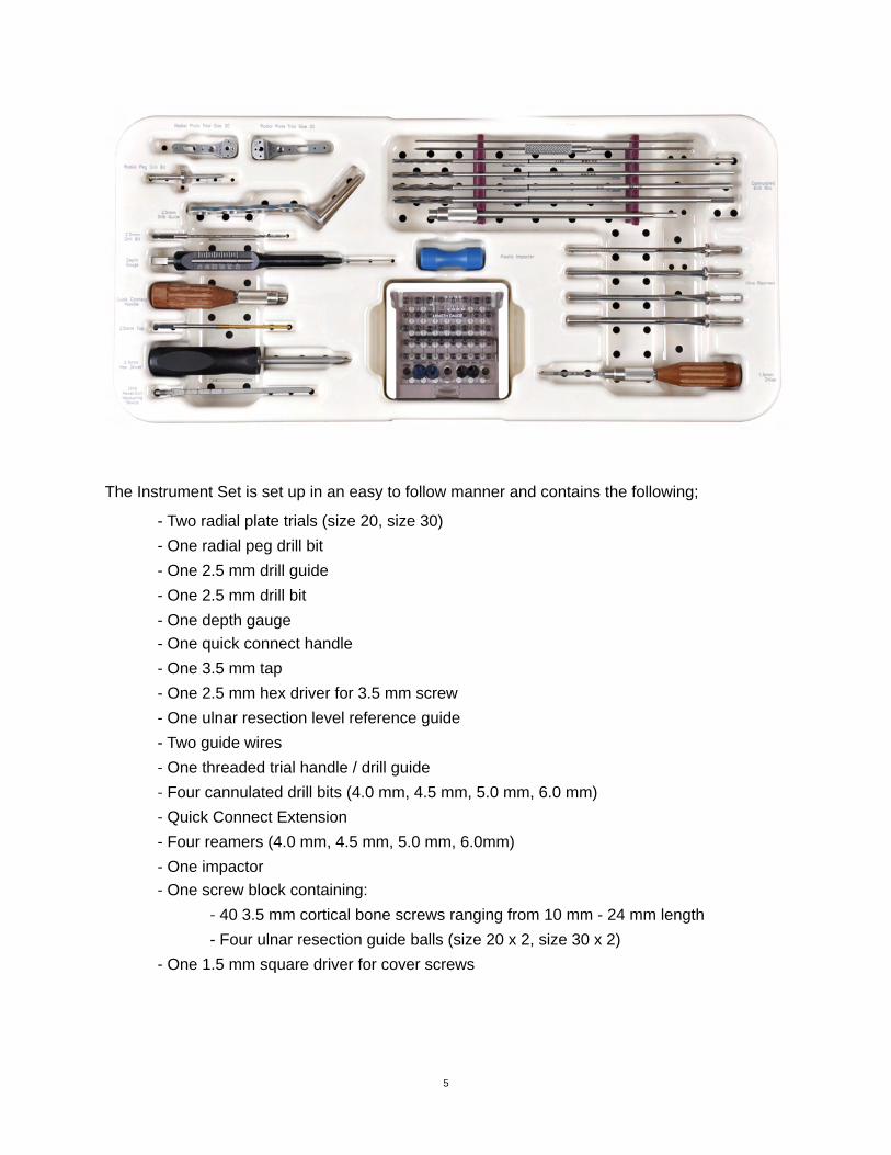
The Instrument Set is set up in an easy to follow manner and contains the following;! - Two radial plate trials (size 20, size 30)! - One radial peg drill bit! - One 2.5 mm drill guide! - One 2.5 mm drill bit! - One depth gauge! - One quick connect handle! - One 3.5 mm tap! - One 2.5 mm hex driver for 3.5 mm screw! - One ulnar resection level reference guide! - Two guide wires
- One threaded trial handle / drill guide- Four cannulated drill bits (4.0 mm, 4.5 mm, 5.0 mm, 6.0 mm)- Quick Connect Extension
! - Four reamers (4.0 mm, 4.5 mm, 5.0 mm, 6.0mm)! - One impactor!
- One screw block containing:- 40 3.5 mm cortical bone screws ranging from 10 mm - 24 mm length
! ! - Four ulnar resection guide balls (size 20 x 2, size 30 x 2)! - One 1.5 mm square driver for cover screws
5
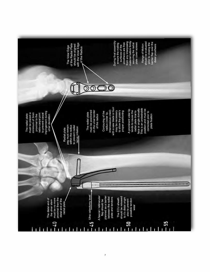
TEMPLATINGTemplates are provided for use with graded scale x-rays to determine the best size of prosthesis as well as the best position for placement. The templates display options including two sizes of radial components and eighteen sizes of ulnar stems. When utilizing templates, the radial plate should be placed no closer to the distal articular surface of the radius than 3 mm. This is to prevent possible carpal impingement with the plate when the wrist is in ulnar deviation. Proximal placement of the plate can vary between the minimum of 3 mm from the radio-carpal joint up to 2 cm depending on the width of the radius. The contour of the plate generally allows good bone to plate contact, but deformities of the radius must be considered. Templates aid with pre-operative planning if any radial contouring is necessary. On the lateral plane, templates are used to check size and placement of the prosthesis. The chosen size should not protrude into the dorsal or volar planes of the extensors or flexors. The plate should be placed precisely on the ulnar border of the radius. Ulnar stems are selected by comparing their diameters to the medullary cavitiy and their lengths to any loss of distal ulna. A templating service is offered by Aptis Medical to assist with patient selection, prosthesis selection and prosthesis placement. The service also provides notes intended to assist with each individual case. (Fig. 1)
During the procedure, x-ray or image intensifier views similar to templated images will confirm accurate placement of the radial plate. A true lateral image should show the plate in a perfectly squared view (not tilted). If the plate is tilted dorsally it could potentially cause unnecessary wear on the extensors.
Note: When imaging during the procedure to assess implant position relative to the anatomy, centralize the area of concern within the image to avoid parabolic distortion.
6
7
SURGICAL PROCEDUREPatient Preparation
The procedure is generally accomplished under axillary block and involves standard methods of prepping and draping for the upper extremity. An adhesive plastic surgical barrier drape is applied to reduce contact between the skin and the implant. A tourniquet is always used with a pressure setting of approximately 250 mm Hg (approximately 100 mm Hg above the patient’s systolic pressure).
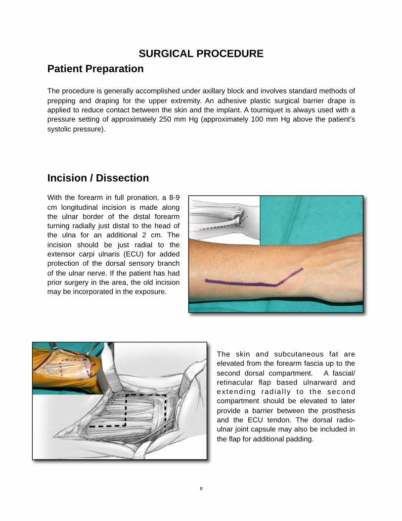
Incision / DissectionWith the forearm in full pronation, a 8-9 cm longitudinal incision is made along the ulnar border of the distal forearm turning radially just distal to the head of the ulna for an additional 2 cm. The incision should be just radial to the extensor carpi ulnaris (ECU) for added protection of the dorsal sensory branch of the ulnar nerve. If the patient has had prior surgery in the area, the old incision may be incorporated in the exposure.
The skin and subcutaneous fat are elevated from the forearm fascia up to the second dorsal compartment. A fascial/retinacular flap based ulnarward and ex tend ing rad ia l l y to the second compartment should be elevated to later provide a barrier between the prosthesis and the ECU tendon. The dorsal radio-ulnar joint capsule may also be included in the flap for additional padding.
8
!
!
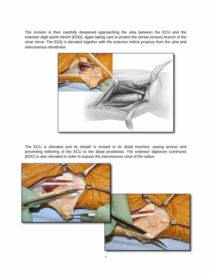
The incision is then carefully deepened approaching the ulna between the ECU and the extensor digiti quinti minimi (EDQ), again taking care to protect the dorsal sensory branch of the ulnar nerve. The EDQ is elevated together with the extensor indicis proprius from the ulna and interosseous membrane.
The ECU is elevated and its sheath is incised to its distal insertion, easing access and preventing tethering of the ECU to the distal prosthesis. The extensor digitorum communis (EDC) is also elevated in order to expose the interosseous crest of the radius.
9
!
!
Ulna Head Excision
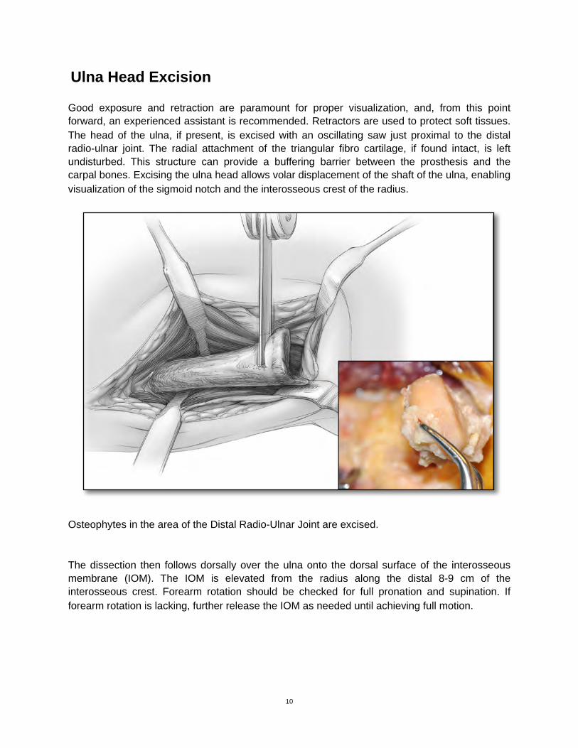
Good exposure and retraction are paramount for proper visualization, and, from this point forward, an experienced assistant is recommended. Retractors are used to protect soft tissues. The head of the ulna, if present, is excised with an oscillating saw just proximal to the distal radio-ulnar joint. The radial attachment of the triangular fibro cartilage, if found intact, is left undisturbed. This structure can provide a buffering barrier between the prosthesis and the carpal bones. Excising the ulna head allows volar displacement of the shaft of the ulna, enabling visualization of the sigmoid notch and the interosseous crest of the radius.
Osteophytes in the area of the Distal Radio-Ulnar Joint are excised.
The dissection then follows dorsally over the ulna onto the dorsal surface of the interosseous membrane (IOM). The IOM is elevated from the radius along the distal 8-9 cm of the interosseous crest. Forearm rotation should be checked for full pronation and supination. If forearm rotation is lacking, further release the IOM as needed until achieving full motion.
10
!
Radial Plate Trial Positioning
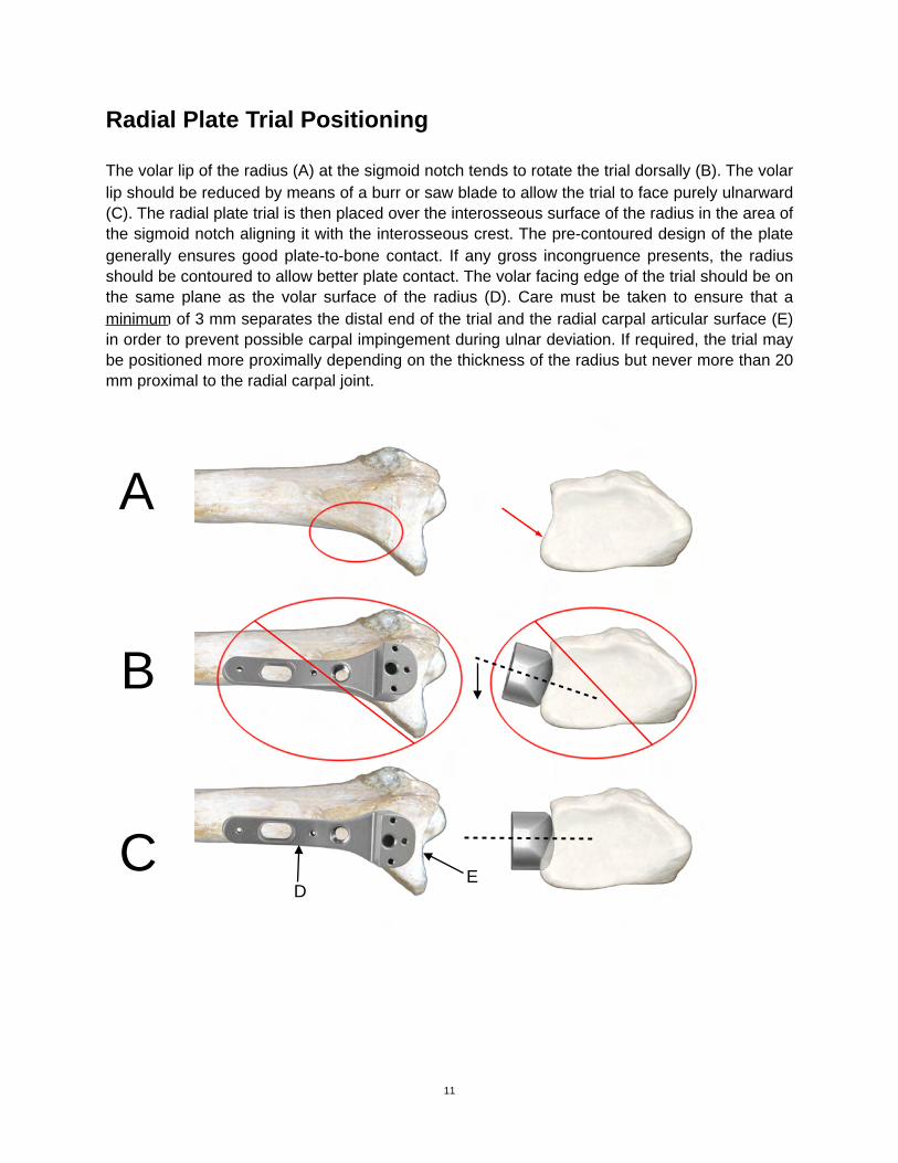
The volar lip of the radius (A) at the sigmoid notch tends to rotate the trial dorsally (B). The volar lip should be reduced by means of a burr or saw blade to allow the trial to face purely ulnarward (C). The radial plate trial is then placed over the interosseous surface of the radius in the area of the sigmoid notch aligning it with the interosseous crest. The pre-contoured design of the plate generally ensures good plate-to-bone contact. If any gross incongruence presents, the radius should be contoured to allow better plate contact. The volar facing edge of the trial should be on the same plane as the volar surface of the radius (D). Care must be taken to ensure that a minimum of 3 mm separates the distal end of the trial and the radial carpal articular surface (E) in order to prevent possible carpal impingement during ulnar deviation. If required, the trial may be positioned more proximally depending on the thickness of the radius but never more than 20 mm proximal to the radial carpal joint.
11
A
B
CD
E
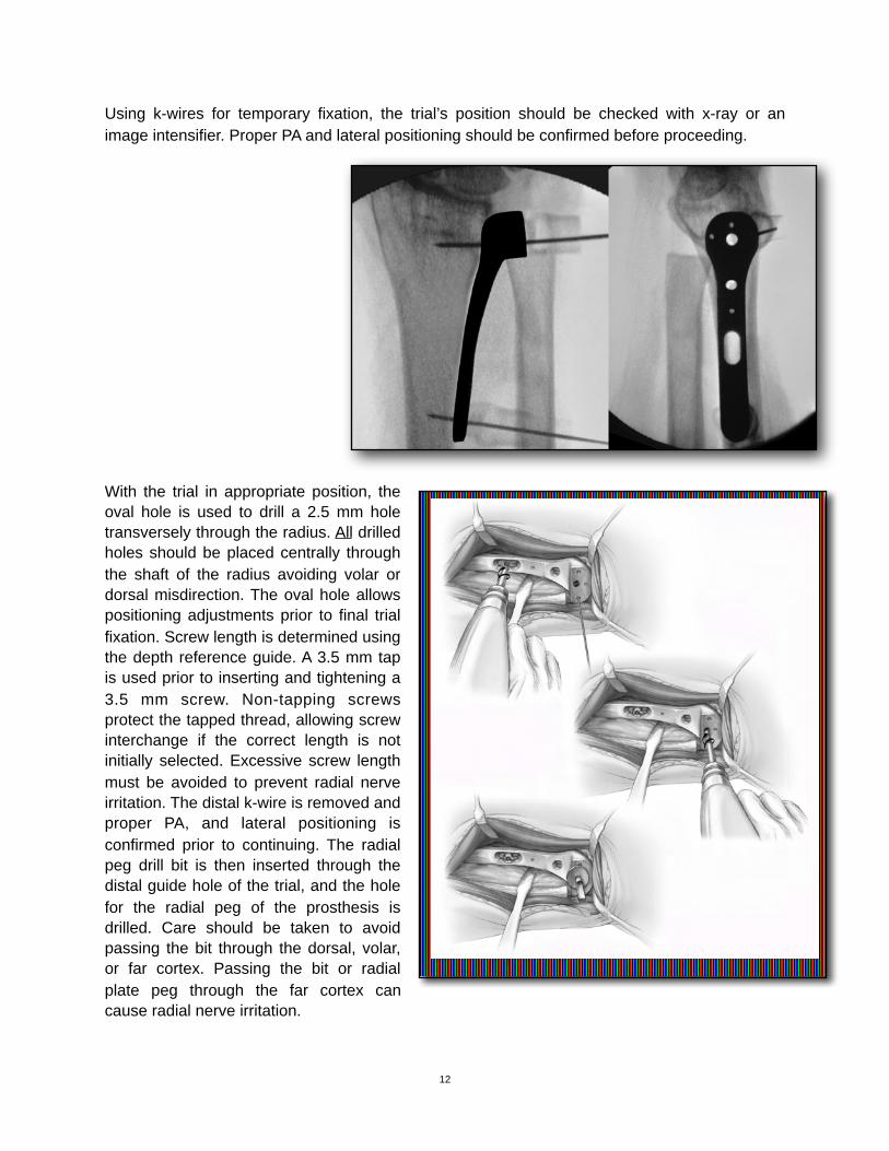
Using k-wires for temporary fixation, the trial’s position should be checked with x-ray or an image intensifier. Proper PA and lateral positioning should be confirmed before proceeding.
With the trial in appropriate position, the oval hole is used to drill a 2.5 mm hole transversely through the radius. All drilled holes should be placed centrally through the shaft of the radius avoiding volar or dorsal misdirection. The oval hole allows positioning adjustments prior to final trial fixation. Screw length is determined using the depth reference guide. A 3.5 mm tap is used prior to inserting and tightening a 3.5 mm screw. Non-tapping screws protect the tapped thread, allowing screw interchange if the correct length is not initially selected. Excessive screw length must be avoided to prevent radial nerve irritation. The distal k-wire is removed and proper PA, and lateral positioning is confirmed prior to continuing. The radial peg drill bit is then inserted through the distal guide hole of the trial, and the hole for the radial peg of the prosthesis is drilled. Care should be taken to avoid passing the bit through the dorsal, volar, or far cortex. Passing the bit or radial plate peg through the far cortex can cause radial nerve irritation.
12
!
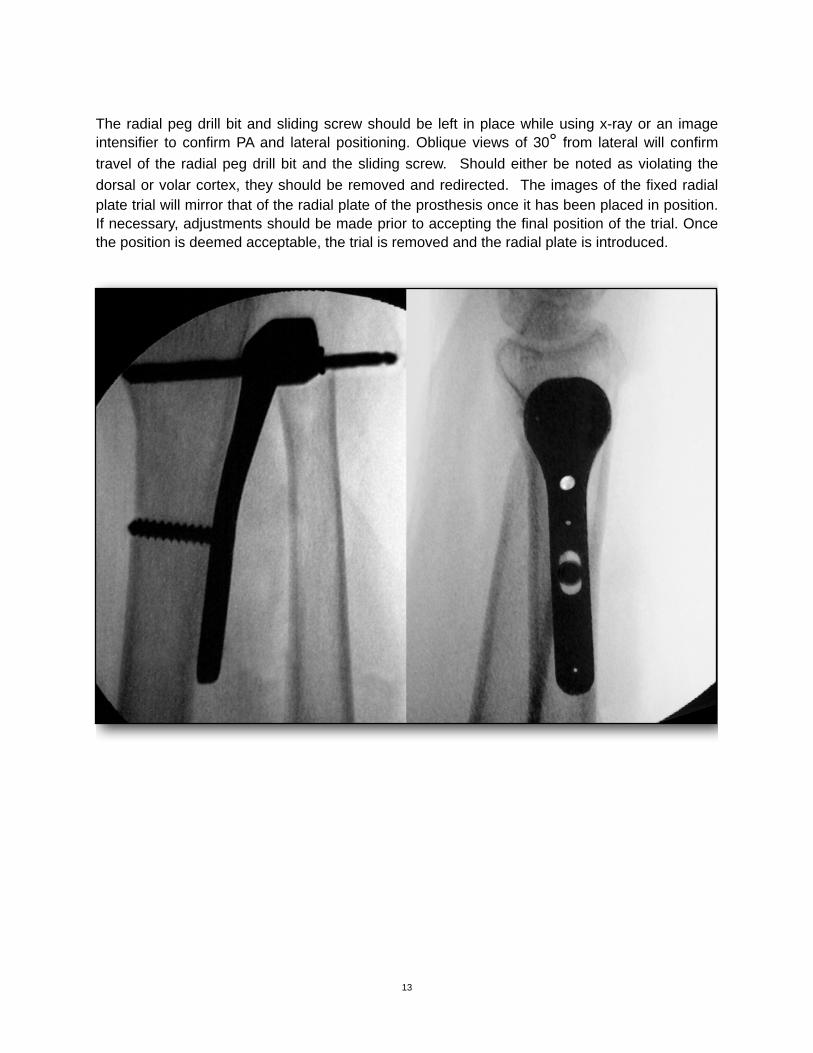
The radial peg drill bit and sliding screw should be left in place while using x-ray or an image intensifier to confirm PA and lateral positioning. Oblique views of 30° from lateral will confirm travel of the radial peg drill bit and the sliding screw. Should either be noted as violating the dorsal or volar cortex, they should be removed and redirected. The images of the fixed radial plate trial will mirror that of the radial plate of the prosthesis once it has been placed in position. If necessary, adjustments should be made prior to accepting the final position of the trial. Once the position is deemed acceptable, the trial is removed and the radial plate is introduced.
13
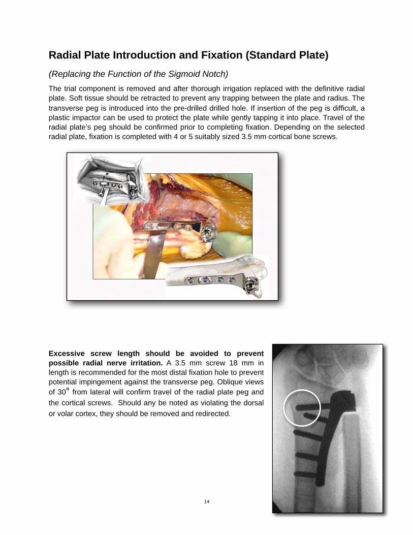
Radial Plate Introduction and Fixation (Standard Plate)(Replacing the Function of the Sigmoid Notch)The trial component is removed and after thorough irrigation replaced with the definitive radial plate. Soft tissue should be retracted to prevent any trapping between the plate and radius. The transverse peg is introduced into the pre-drilled drilled hole. If insertion of the peg is difficult, a plastic impactor can be used to protect the plate while gently tapping it into place. Travel of the radial plate’s peg should be confirmed prior to completing fixation. Depending on the selected radial plate, fixation is completed with 4 or 5 suitably sized 3.5 mm cortical bone screws.
Excessive screw length should be avoided to prevent possible radial nerve irritation. A 3.5 mm screw 18 mm in length is recommended for the most distal fixation hole to prevent potential impingement against the transverse peg. Oblique views of 30° from lateral will confirm travel of the radial plate peg and the cortical screws. Should any be noted as violating the dorsal or volar cortex, they should be removed and redirected.
14
!
!
Locking Plate Surgical Technique Addendum to DRUJ Surgical Technique- 14-0002
The surgical technique for the locking plate is similar to the non-locking plate with the following provisos during the plate placement. First, ensure that the trial plate is properly aligned, on the ulnar border of the radius. The trial cannot be angulated volar or dorsal as this would misdirect the locking screws when inserted and fixed to the radial plate. Use an x-ray or image intensifier to confirm on the lateral view of the distal forearm the trial plate’s position. The position must allow all drilling and subsequent screws to travel from the ulnar border of the radius to the radial side of the radius with no volar or dorsal misdirection.
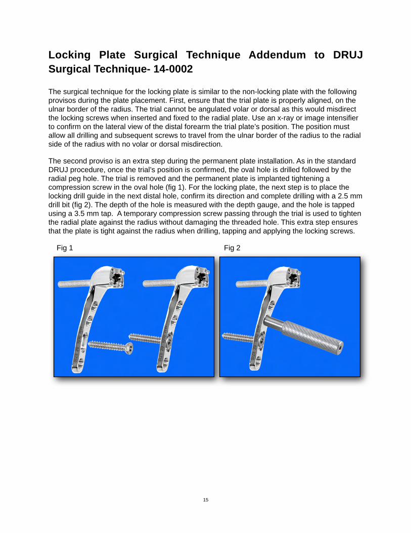
The second proviso is an extra step during the permanent plate installation. As in the standard DRUJ procedure, once the trial’s position is confirmed, the oval hole is drilled followed by the radial peg hole. The trial is removed and the permanent plate is implanted tightening a compression screw in the oval hole (fig 1). For the locking plate, the next step is to place the locking drill guide in the next distal hole, confirm its direction and complete drilling with a 2.5 mm drill bit (fig 2). The depth of the hole is measured with the depth gauge, and the hole is tapped using a 3.5 mm tap. A temporary compression screw passing through the trial is used to tighten the radial plate against the radius without damaging the threaded hole. This extra step ensures that the plate is tight against the radius when drilling, tapping and applying the locking screws.
Fig 1! ! ! ! ! ! Fig 2
! ! ! ! ! !
15
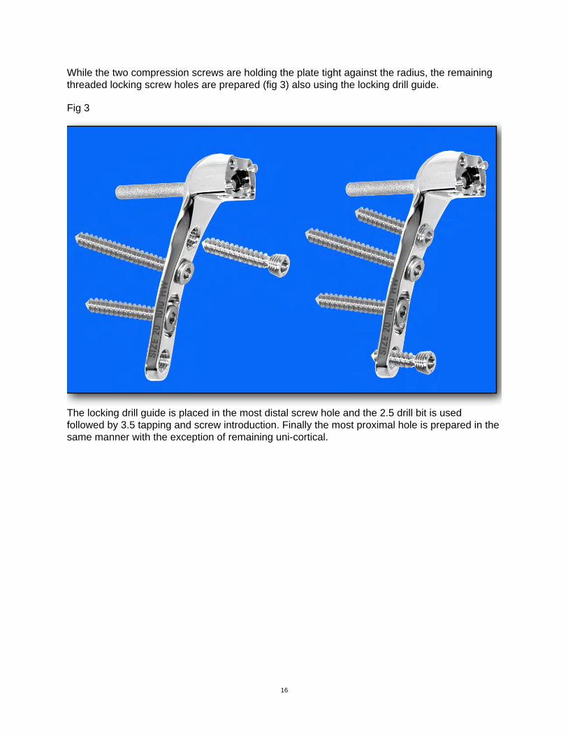
While the two compression screws are holding the plate tight against the radius, the remaining threaded locking screw holes are prepared (fig 3) also using the locking drill guide.
Fig 3
The locking drill guide is placed in the most distal screw hole and the 2.5 drill bit is used followed by 3.5 tapping and screw introduction. Finally the most proximal hole is prepared in the same manner with the exception of remaining uni-cortical.
16
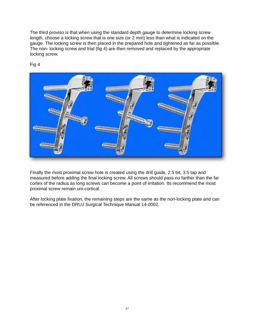
The third proviso is that when using the standard depth gauge to determine locking screw length, choose a locking screw that is one size (or 2 mm) less than what is indicated on the gauge. The locking screw is then placed in the prepared hole and tightened as far as possible. The non- locking screw and trial (fig 4) are then removed and replaced by the appropriate locking screw.
Fig 4
Finally the most proximal screw hole is created using the drill guide, 2.5 bit, 3.5 tap and measured before adding the final locking screw. All screws should pass no farther than the far cortex of the radius as long screws can become a point of irritation. Its recommend the most proximal screw remain uni-cortical.
After locking plate fixation, the remaining steps are the same as the non-locking plate and can be referenced in the DRUJ Surgical Technique Manual 14-0002.
17
!
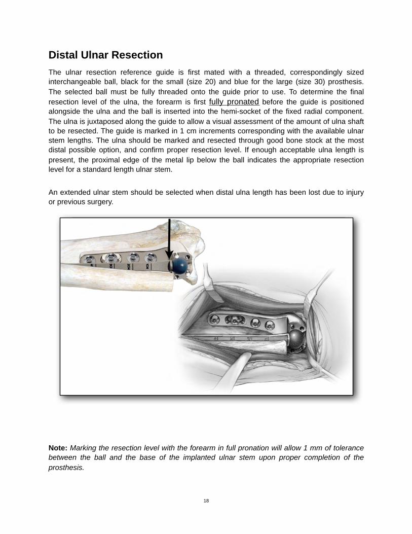
Distal Ulnar ResectionThe ulnar resection reference guide is first mated with a threaded, correspondingly sized interchangeable ball, black for the small (size 20) and blue for the large (size 30) prosthesis. The selected ball must be fully threaded onto the guide prior to use. To determine the final resection level of the ulna, the forearm is first fully pronated before the guide is positioned alongside the ulna and the ball is inserted into the hemi-socket of the fixed radial component. The ulna is juxtaposed along the guide to allow a visual assessment of the amount of ulna shaft to be resected. The guide is marked in 1 cm increments corresponding with the available ulnar stem lengths. The ulna should be marked and resected through good bone stock at the most distal possible option, and confirm proper resection level. If enough acceptable ulna length is present, the proximal edge of the metal lip below the ball indicates the appropriate resection level for a standard length ulnar stem.
An extended ulnar stem should be selected when distal ulna length has been lost due to injury or previous surgery.
Note: Marking the resection level with the forearm in full pronation will allow 1 mm of tolerance between the ball and the base of the implanted ulnar stem upon proper completion of the prosthesis.
18
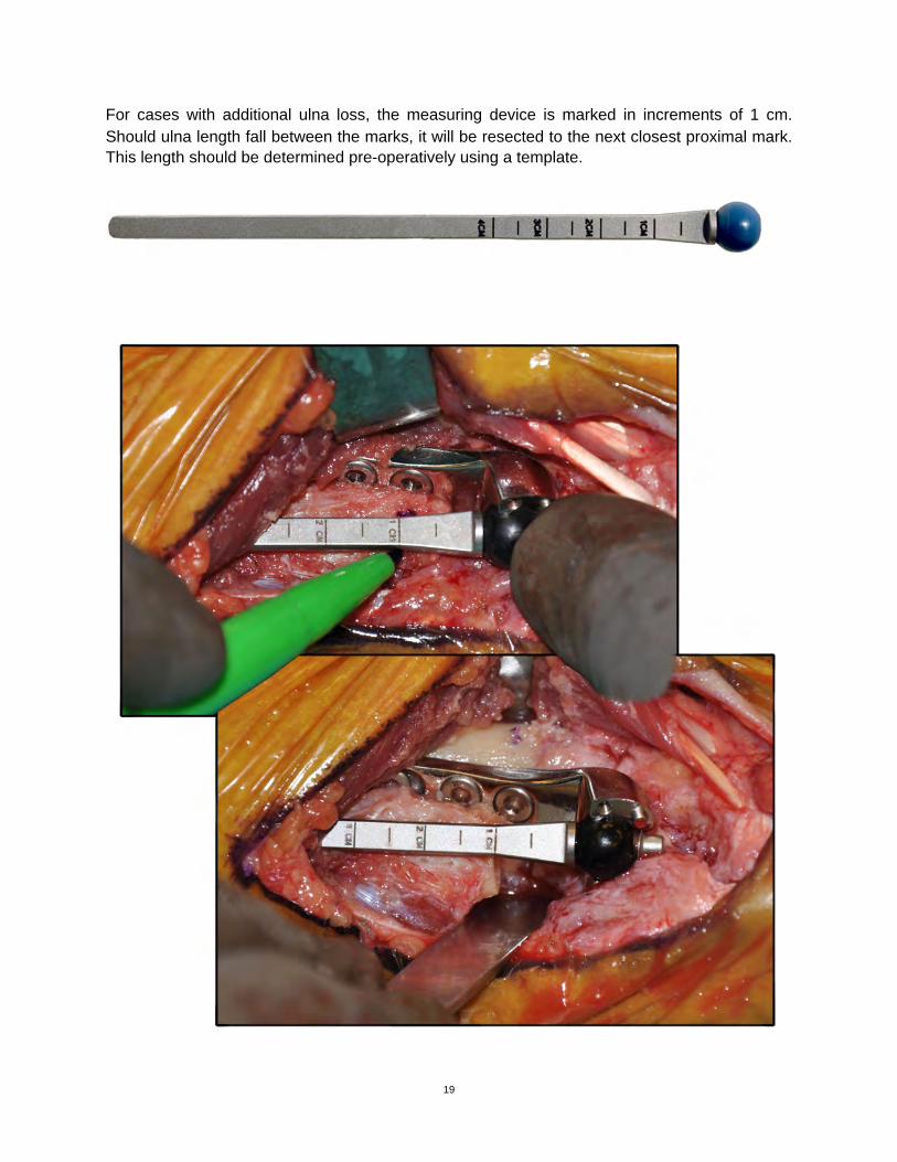
For cases with additional ulna loss, the measuring device is marked in increments of 1 cm. Should ulna length fall between the marks, it will be resected to the next closest proximal mark. This length should be determined pre-operatively using a template.
19
!
!
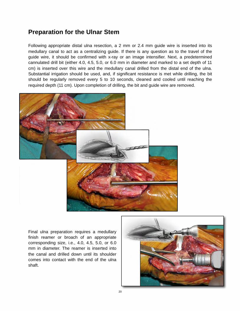
Preparation for the Ulnar Stem
Following appropriate distal ulna resection, a 2 mm or 2.4 mm guide wire is inserted into its medullary canal to act as a centralizing guide. If there is any question as to the travel of the guide wire, it should be confirmed with x-ray or an image intensifier. Next, a predetermined cannulated drill bit (either 4.0, 4.5, 5.0, or 6.0 mm in diameter and marked to a set depth of 11 cm) is inserted over this wire and the medullary canal drilled from the distal end of the ulna. Substantial irrigation should be used, and, if significant resistance is met while drilling, the bit should be regularly removed every 5 to 10 seconds, cleaned and cooled until reaching the required depth (11 cm). Upon completion of drilling, the bit and guide wire are removed.
11.
Final ulna preparation requires a medullary finish reamer or broach of an appropriate corresponding size, i.e., 4.0, 4.5, 5.0, or 6.0 mm in diameter. The reamer is inserted into the canal and drilled down until its shoulder comes into contact with the end of the ulna shaft.
20
!
!
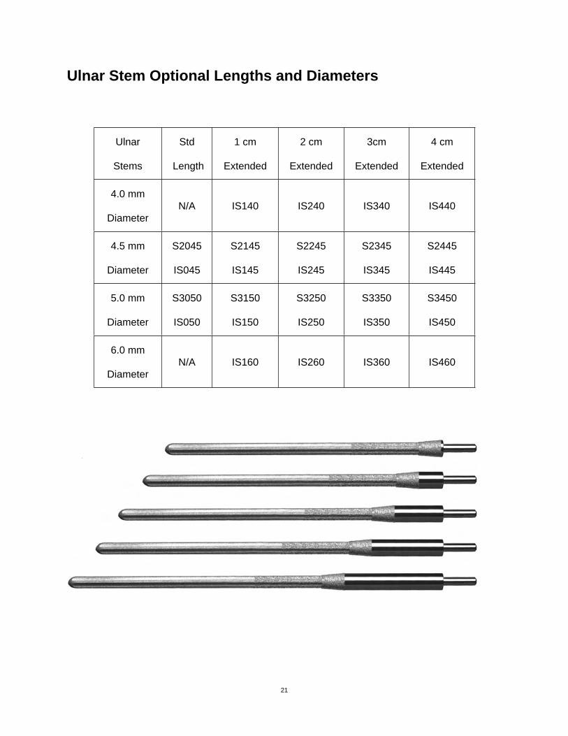
Ulnar Stem Optional Lengths and Diameters
Ulnar
Stems
Std
Length
1 cm
Extended
2 cm
Extended
3cm
Extended
4 cm
Extended
4.0 mm
DiameterN/A IS140 IS240 IS340 IS440
4.5 mm
Diameter
S2045
IS045
S2145
IS145
S2245
IS245
S2345
IS345
S2445
IS445
5.0 mm
Diameter
S3050
IS050
S3150
IS150
S3250
IS250
S3350
IS350
S3450
IS450
6.0 mm
DiameterN/A IS160 IS260 IS360 IS460
21
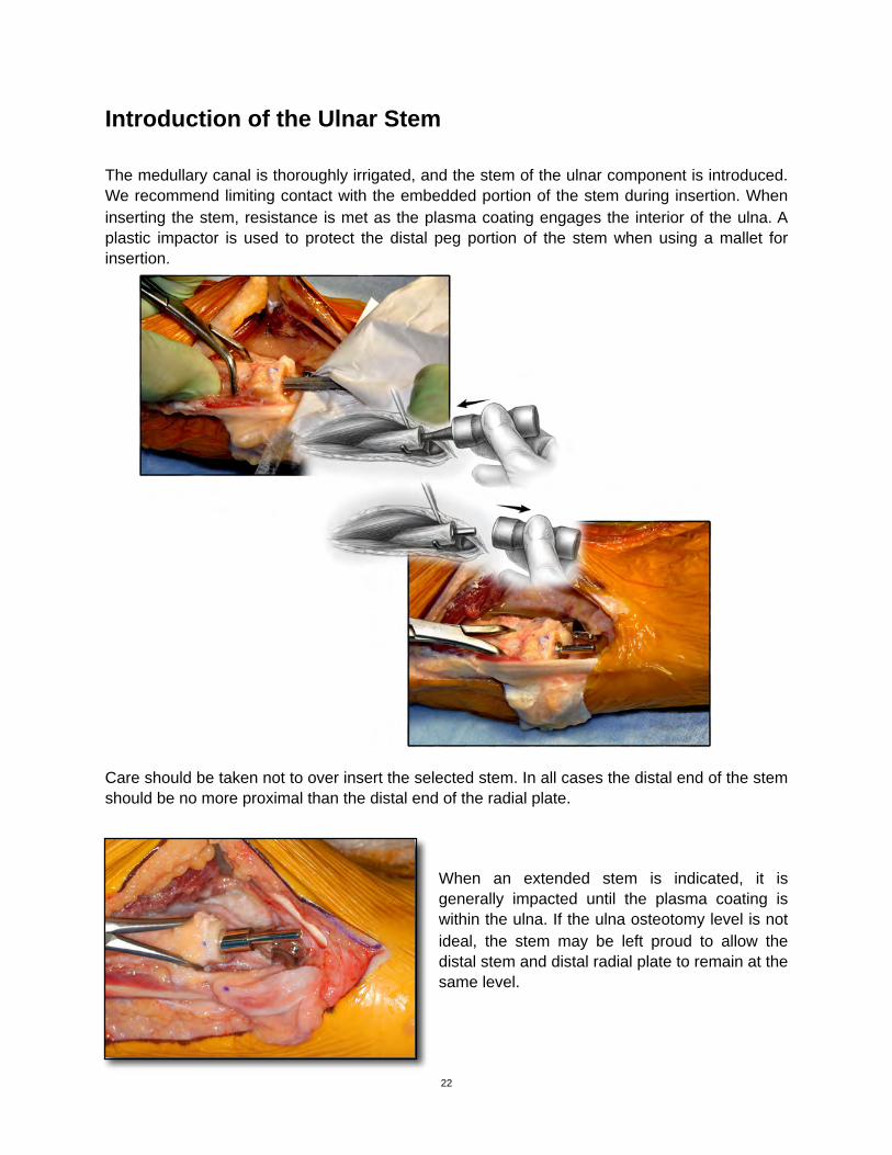
Introduction of the Ulnar Stem
The medullary canal is thoroughly irrigated, and the stem of the ulnar component is introduced. We recommend limiting contact with the embedded portion of the stem during insertion. When inserting the stem, resistance is met as the plasma coating engages the interior of the ulna. A plastic impactor is used to protect the distal peg portion of the stem when using a mallet for insertion.
Care should be taken not to over insert the selected stem. In all cases the distal end of the stem should be no more proximal than the distal end of the radial plate.
When an extended stem is indicated, it is generally impacted until the plasma coating is within the ulna. If the ulna osteotomy level is not ideal, the stem may be left proud to allow the distal stem and distal radial plate to remain at the same level.
22
!
!
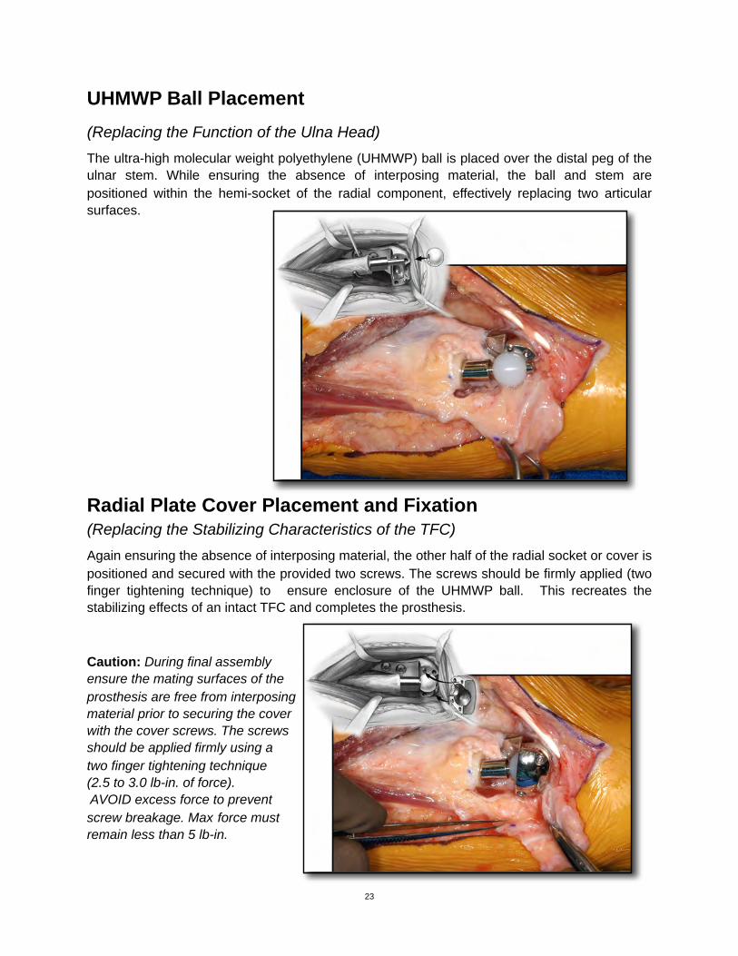
UHMWP Ball Placement(Replacing the Function of the Ulna Head)The ultra-high molecular weight polyethylene (UHMWP) ball is placed over the distal peg of the ulnar stem. While ensuring the absence of interposing material, the ball and stem are positioned within the hemi-socket of the radial component, effectively replacing two articular surfaces.
Radial Plate Cover Placement and Fixation(Replacing the Stabilizing Characteristics of the TFC)Again ensuring the absence of interposing material, the other half of the radial socket or cover is positioned and secured with the provided two screws. The screws should be firmly applied (two finger tightening technique) to ensure enclosure of the UHMWP ball. This recreates the stabilizing effects of an intact TFC and completes the prosthesis.
Caution: During final assemblyensure the mating surfaces of theprosthesis are free from interposingmaterial prior to securing the coverwith the cover screws. The screwsshould be applied firmly using atwo finger tightening technique(2.5 to 3.0 lb-in. of force). AVOID excess force to preventscrew breakage. Max force mustremain less than 5 lb-in.
23
!
!
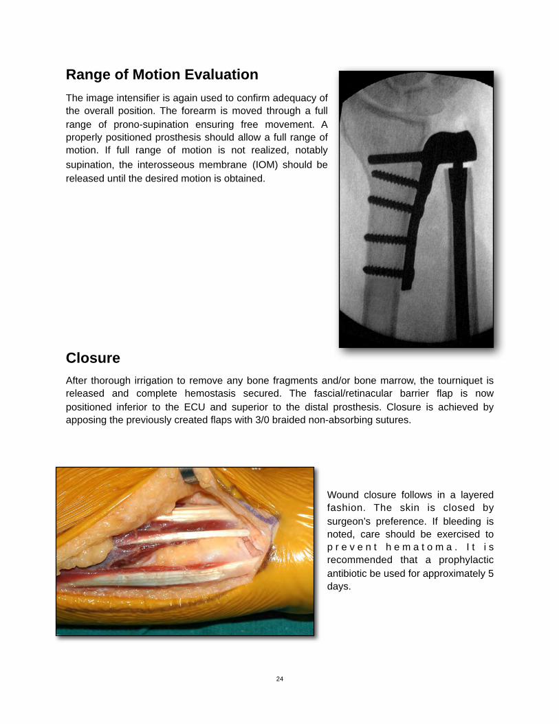
Range of Motion Evaluation The image intensifier is again used to confirm adequacy of the overall position. The forearm is moved through a full range of prono-supination ensuring free movement. A properly positioned prosthesis should allow a full range of motion. If full range of motion is not realized, notably supination, the interosseous membrane (IOM) should be released until the desired motion is obtained.
ClosureAfter thorough irrigation to remove any bone fragments and/or bone marrow, the tourniquet is released and complete hemostasis secured. The fascial/retinacular barrier flap is now positioned inferior to the ECU and superior to the distal prosthesis. Closure is achieved by apposing the previously created flaps with 3/0 braided non-absorbing sutures.
Wound closure follows in a layered fashion. The skin is closed by surgeon’s preference. If bleeding is noted, care should be exercised to p r e v e n t h e m a t o m a . I t i s recommended that a prophylactic antibiotic be used for approximately 5 days.
24
!
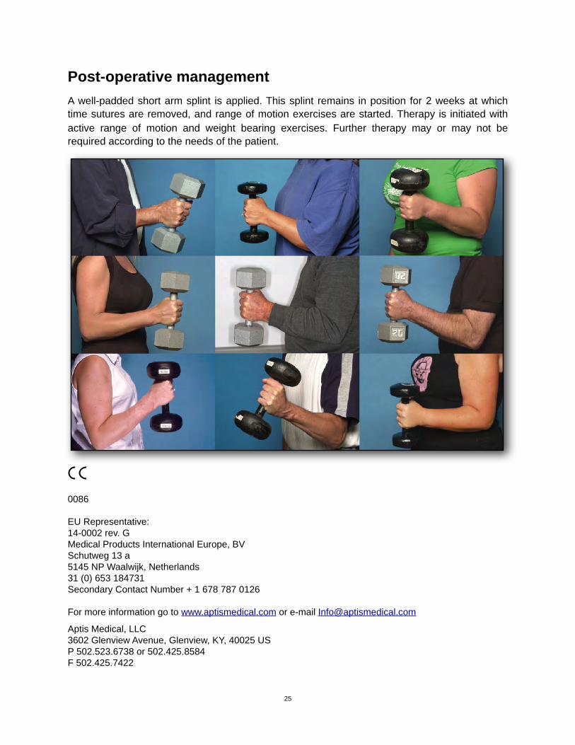
Post-operative managementA well-padded short arm splint is applied. This splint remains in position for 2 weeks at which time sutures are removed, and range of motion exercises are started. Therapy is initiated with active range of motion and weight bearing exercises. Further therapy may or may not be required according to the needs of the patient.
!0086
EU Representative:14-0002 rev. GMedical Products International Europe, BVSchutweg 13 a5145 NP Waalwijk, Netherlands31 (0) 653 184731Secondary Contact Number + 1 678 787 0126
For more information go to www.aptismedical.com or e-mail [email protected] Medical, LLC3602 Glenview Avenue, Glenview, KY, 40025 USP 502.523.6738 or 502.425.8584F 502.425.7422
25
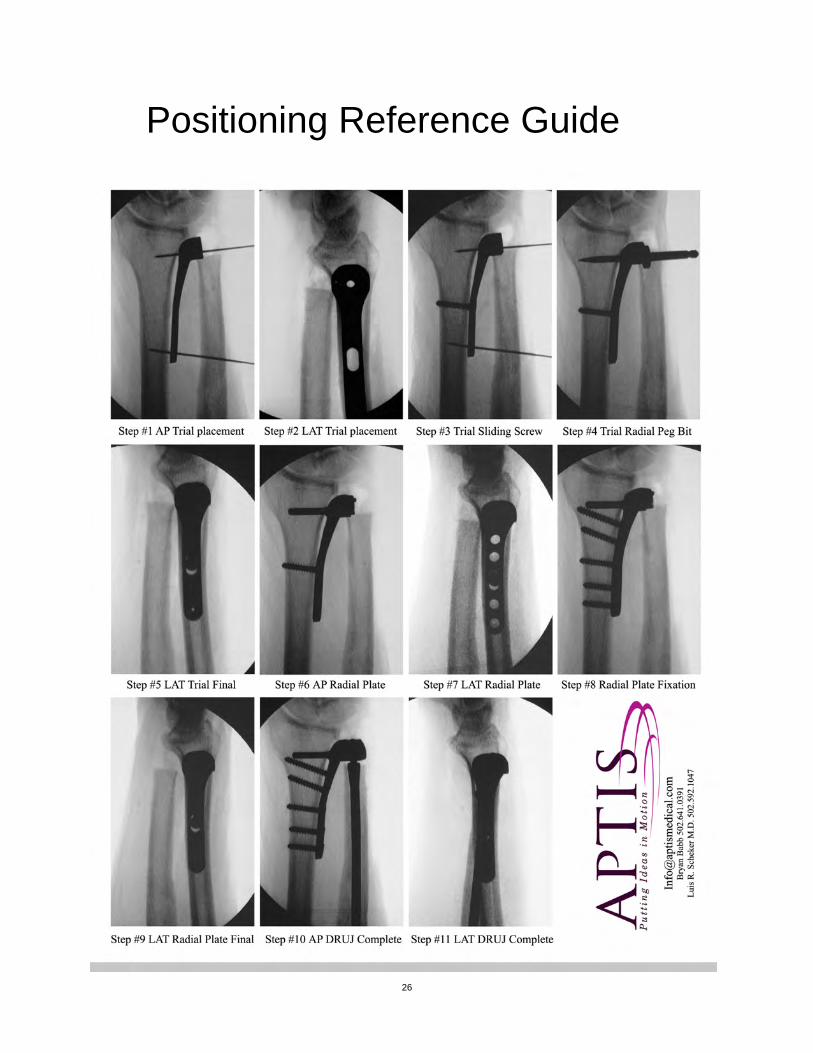
Positioning Reference Guide
26
!

Notes
27