Embed Size (px)
Citation preview
THEMATIC SECTION: SLAG VALORISATION
The Submerged Arc Furnace (SAF): State-of-the-Art Metal Recoveryfrom Nonferrous Slags
Bernd Friedrich1 • Michael Kalisch2 • David Friedmann1 • Rolf Degel2 • Frank Kaußen1 • Jorn Bohlke1
� The Minerals, Metals & Materials Society 2018
AbstractThe submerged electric arc furnace (SAF) has proven a versatile unit in numerous metallurgical applications for more than a
century. Countless innovations have made this furnace type become the most commonly used furnace for increased metal
recoveries and slag-cleaning operations. In many applications, SAFs are also employed as primary melting units (e.g., Ni
Laterites, Si production, FeMn, FeCr, etc.). Furnace power supply as well as capacities has been continuously increased over the
years so thatmodern SAFs can reachmore than 100 MVA aswell asmore than 100 tph in throughput. The present paper aims to
provide a thorough overview of the principles and buildup of modern SAFs and to present various examples from recent
industrial installations as well as current topics in pyrometallurgical research. Examples of the buildup and special equipment
(such as cooled wall panels, Soderberg electrodes, etc.) of modern SAFs are demonstrated. The paper also presents metallur-
gical, thermochemical, and physical fundamentals of slag cleaning as well as particle settling. Furthermore, industrial examples
from two African sites are discussed, which highlight the advantages of the SAF for metal recoveries. Special emphasis is given
to an innovative slag-cleaning concept through magnetic agitation. Research topics presented range from the inertization of red
mud, to Co recovery through the retreatment of dumped slag and the valorization of Pb- and Zn-containing slags.
Keywords SAF � Submerged-arc-furnace � Slag-cleaning � Slag-washing-machine � Cobalt-recovery � Redmud
Introduction
In metallurgical production, the traditional aim is to
increase recovery of metal to the maximum. It becomes
apparent that the application of the submerged arc furnace
(SAF) in nonferrous metallurgy processes is increasing, in
particular for the extraction of zinc, lead, copper and
nickel, but also for the processing of residues and stripping
of slag. The SMS group has been developing this tech-
nology for 100 years, and has supplied a diverse market
with about 700 furnaces and major furnace components [1].
During this time, numerous applications were continuously
being developed in order to serve the demands of various
users [2]. Especially more than 20 slag-cleaning furnaces
have been supplied in the last 40 years. Slag-cleaning
furnaces are commonly connected to smelting units such as
Teniente and Noranda converter, Outokumpu flash smelter,
reverbertory furnaces, etc. The main function of the fur-
nace is the reduction of the matte and metal level in the
slag. Depending on the upstream process, the slag is either
liquid-charged via launders into the furnace or is cold-
charged in solid form via conventional feeding systems.
Principle of SAF
The SAF works with electric energy which is converted
into heat, mainly using the electric resistance of the burden
or molten slag. The electrodes are immersed in the melt
The contributing editor for this article was Annelies Malfliet.
& David Friedmann
Bernd Friedrich
Michael Kalisch
Rolf Degel
1 IME Process Metallurgy and Metal Recycling, RWTH
Aachen University, Intzestr. 3, 52072 Aachen, Germany
2 SMS Group GmbH, Eduard-Schloemann-Straße 4,
Dusseldorf 40237, Germany
123
Journal of Sustainable Metallurgyhttps://doi.org/10.1007/s40831-017-0153-1(0123456789().,-volV)(0123456789().,-volV)
which provides the required energy exchange area between
electrode and melt. The melt is the heat exchange medium
which supplies the energy required for melting and
chemical reactions of the charge [3]. The submerged arc
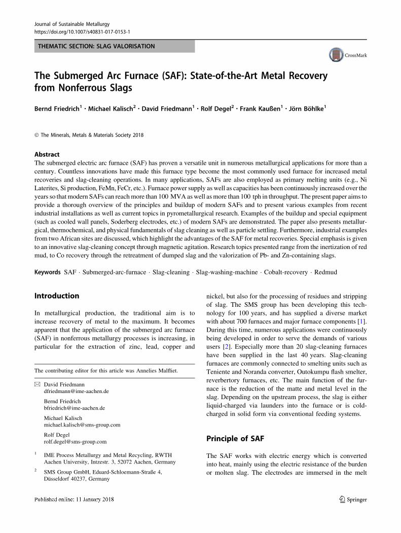
furnace comprises the following major equipment parts as
seen in Fig. 1.
A typical furnace with slag operation comprises a round
or rectangular furnace shell with tap holes for slag, matte or
metal. The furnace shell is refractory lined and—if addi-
tional shell cooling is required by the process—water-
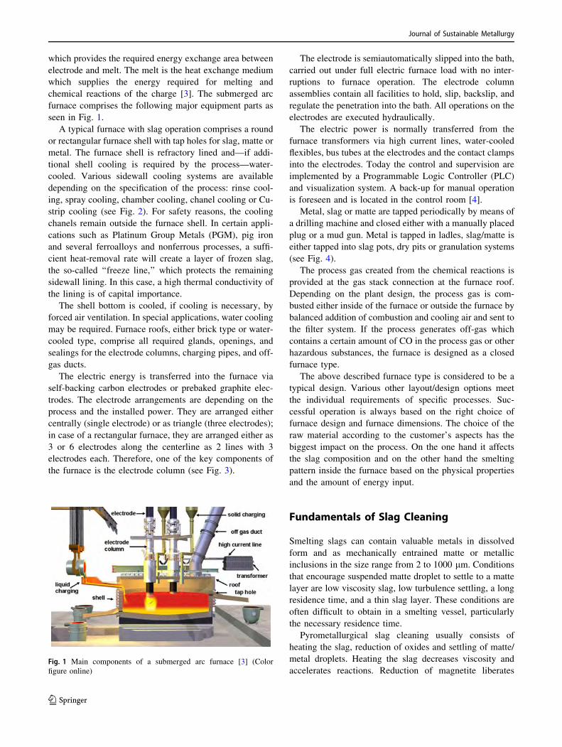
cooled. Various sidewall cooling systems are available
depending on the specification of the process: rinse cool-
ing, spray cooling, chamber cooling, chanel cooling or Cu-
strip cooling (see Fig. 2). For safety reasons, the cooling
chanels remain outside the furnace shell. In certain appli-
cations such as Platinum Group Metals (PGM), pig iron
and several ferroalloys and nonferrous processes, a suffi-
cient heat-removal rate will create a layer of frozen slag,
the so-called ‘‘freeze line,’’ which protects the remaining
sidewall lining. In this case, a high thermal conductivity of
the lining is of capital importance.
The shell bottom is cooled, if cooling is necessary, by
forced air ventilation. In special applications, water cooling
may be required. Furnace roofs, either brick type or water-
cooled type, comprise all required glands, openings, and
sealings for the electrode columns, charging pipes, and off-
gas ducts.
The electric energy is transferred into the furnace via
self-backing carbon electrodes or prebaked graphite elec-
trodes. The electrode arrangements are depending on the
process and the installed power. They are arranged either
centrally (single electrode) or as triangle (three electrodes);
in case of a rectangular furnace, they are arranged either as
3 or 6 electrodes along the centerline as 2 lines with 3
electrodes each. Therefore, one of the key components of
the furnace is the electrode column (see Fig. 3).
The electrode is semiautomatically slipped into the bath,
carried out under full electric furnace load with no inter-
ruptions to furnace operation. The electrode column
assemblies contain all facilities to hold, slip, backslip, and
regulate the penetration into the bath. All operations on the
electrodes are executed hydraulically.
The electric power is normally transferred from the
furnace transformers via high current lines, water-cooled
flexibles, bus tubes at the electrodes and the contact clamps
into the electrodes. Today the control and supervision are
implemented by a Programmable Logic Controller (PLC)
and visualization system. A back-up for manual operation
is foreseen and is located in the control room [4].
Metal, slag or matte are tapped periodically by means of
a drilling machine and closed either with a manually placed
plug or a mud gun. Metal is tapped in ladles, slag/matte is
either tapped into slag pots, dry pits or granulation systems
(see Fig. 4).
The process gas created from the chemical reactions is
provided at the gas stack connection at the furnace roof.
Depending on the plant design, the process gas is com-
busted either inside of the furnace or outside the furnace by
balanced addition of combustion and cooling air and sent to
the filter system. If the process generates off-gas which
contains a certain amount of CO in the process gas or other
hazardous substances, the furnace is designed as a closed
furnace type.
The above described furnace type is considered to be a
typical design. Various other layout/design options meet
the individual requirements of specific processes. Suc-
cessful operation is always based on the right choice of
furnace design and furnace dimensions. The choice of the
raw material according to the customer’s aspects has the
biggest impact on the process. On the one hand it affects
the slag composition and on the other hand the smelting
pattern inside the furnace based on the physical properties
and the amount of energy input.
Fundamentals of Slag Cleaning
Smelting slags can contain valuable metals in dissolved
form and as mechanically entrained matte or metallic
inclusions in the size range from 2 to 1000 lm. Conditions
that encourage suspended matte droplet to settle to a matte
layer are low viscosity slag, low turbulence settling, a long
residence time, and a thin slag layer. These conditions are
often difficult to obtain in a smelting vessel, particularly
the necessary residence time.
Pyrometallurgical slag cleaning usually consists of
heating the slag, reduction of oxides and settling of matte/
metal droplets. Heating the slag decreases viscosity and
accelerates reactions. Reduction of magnetite liberatesFig. 1 Main components of a submerged arc furnace [3] (Color
figure online)
Journal of Sustainable Metallurgy
123
inclusions and facilitates co-reduction of dissolved metal
oxides. A significant amount of the matte and metal is
present as very fine metallic inclusions, too small for set-
tling. The coalescence of these matte or metal inclusions is
required to remove them from the slag.
Chemical Slag-Cleaning Process
The metals in smelting and converting slags are present
either dissolved, present mostly as ions (e.g., for copper
slag as Cu? ions) or as entrained droplets of matte. The
dissolved metals is associated either with OX- ions (i.e.,
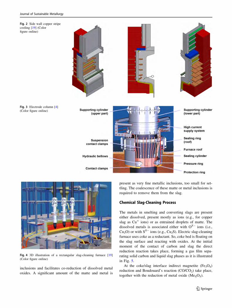
Cu2O) or with SX- ions (e.g., Cu2S). Electric slag-cleaning
furnace uses coke as a reductant. So, coke bed is floating on
the slag surface and reacting with oxides. At the initial
moment of the contact of carbon and slag the direct
reduction reaction takes place, forming a gas film sepa-
rating solid carbon and liquid slag phases as it is illustrated
in Fig. 5.
At the coke/slag interface indirect magnetite (Fe3O4)
reduction and Boudouard’s reaction (CO/CO2) take place,
together with the reduction of metal oxide (MeXOY).
Fig. 2 Side wall copper stripe
cooling [19] (Color
figure online)
Fig. 3 Electrode column [4]
(Color figure online)
Fig. 4 3D illustration of a rectangular slag-cleaning furnace [19]
(Color figure online)
Journal of Sustainable Metallurgy
123
Direct reduction
Fe3O4½ �slag þC ¼ 3 FeO½ �slag þCO ð1Þ
FeO½ �slag þC ¼ Fef gmetal þCO ð2Þ
MeXOY½ �slag þC ¼ X Mef gmetal þCO ð3Þ
Indirect reduction
Fe3O4½ �slag þCO ¼ 3 FeO½ �slag þCO2 ð4Þ
FeO½ �slag þCO ¼ Fef gmetal þCO2 ð5Þ
MeXOY½ �slag þCO ¼ X Mef gmetal þCO2 ð6Þ
Boudouard reaction
CO2 þ C ¼ 2CO ð7Þ
Reducing viscosity can be achieved by increasing the
slag temperature, and changing slag chemistry. The main
focus of changing slag chemistry is to reduce the magnetite
that is present within the slag, mainly according to Eqs. (1)
and (4). Other reactions to reduce the magnetite content
involve iron with higher carbon content (4–5%) and sul-
fides [5–7].
Physical Slag-Cleaning Process
Settling rate of spherical body in a liquid is described by
Stokes’s law:
u ¼ 2 qM � qSð Þ g r29 gS
ð8Þ
Matte and metallic inclusions are present in a molten
slag in the form of liquid droplets. The rate of settling of a
liquid, spherical drop in a liquid is given by Hadamard–
Rybczynski formula:
u ¼ qM � qSð Þ g r23 gS
3 gS þ 2 gM3 gS þ gMð Þ ð9Þ
Because slag viscosity is much higher than matte or
metal viscosity (gS � gM) the settling rate of matte and
metallic inclusions in the slag can be calculated using the
modified Hadamard–Rybcznski formula for slag/matte
system:
u ¼ qM � qSð Þ g r23 gS
ð10Þ
The wide range of sizes of inclusions, varying from 2 to
1000 lm, and differences in the settling rates of different
sized droplets cause the droplets to collide and coales-
cence, called gravitational coalescence. The bigger droplets
‘‘wash out’’ the smaller ones by absorbing them as the big
droplets fall faster through the slag than small ones do [8].
It requires precise information about size distribution of
matte and metallic inclusions. E.g., based on the micro-
scopic examination of the slag of 3.5% copper content
from Teniente Converter a typical size distribution of
copper matte inclusions and metallic copper inclusions are
shown in Figs. 6 and 7 [6, 9].
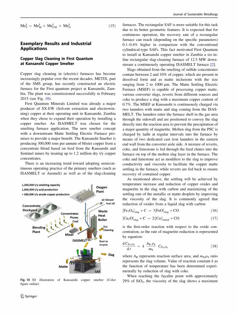
In Fig. 8, the curve for calculation of the copper content
with only gravitational settling (Eq. 10) is given. After 2 h,
the copper content is close to 2%. Also, the copper content
Fig. 5 Slag reduction with coke
floating on its surface [5] (Color
figure online)
Fig. 6 Size distribution of copper matte inclusions in slag form
Teniente Converter [20]
Journal of Sustainable Metallurgy
123
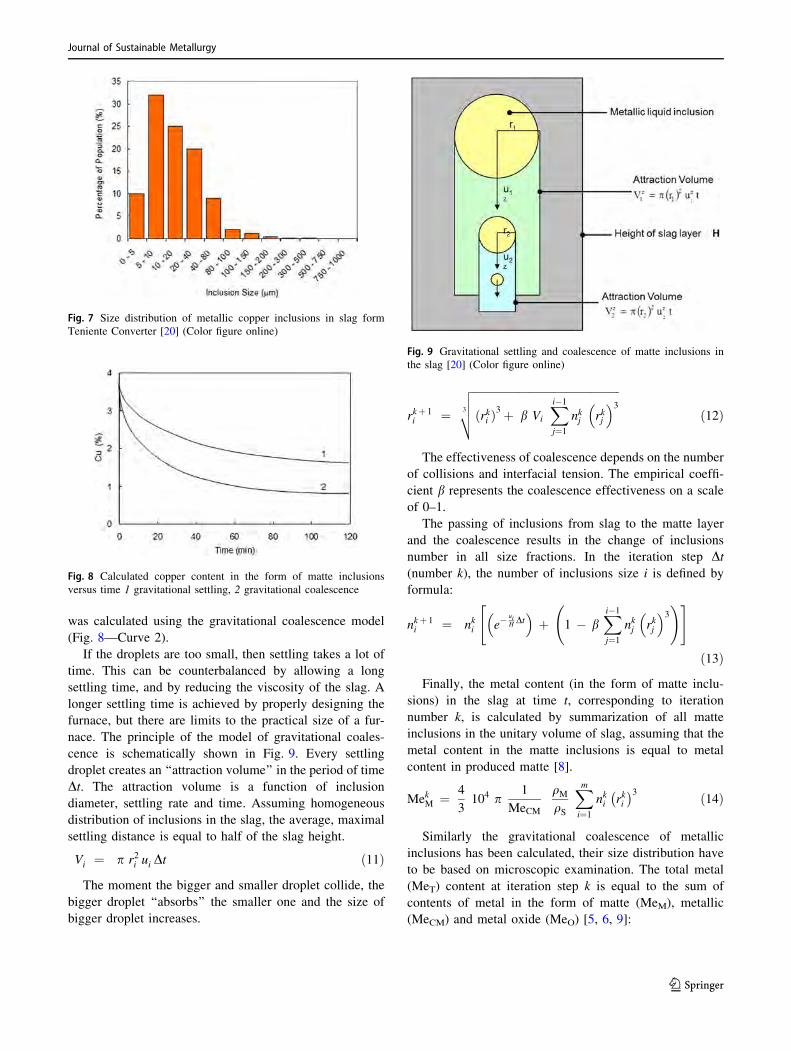
was calculated using the gravitational coalescence model
(Fig. 8—Curve 2).
If the droplets are too small, then settling takes a lot of
time. This can be counterbalanced by allowing a long
settling time, and by reducing the viscosity of the slag. A
longer settling time is achieved by properly designing the
furnace, but there are limits to the practical size of a fur-
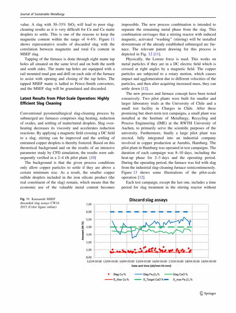
nace. The principle of the model of gravitational coales-
cence is schematically shown in Fig. 9. Every settling
droplet creates an ‘‘attraction volume’’ in the period of time
Dt. The attraction volume is a function of inclusion
diameter, settling rate and time. Assuming homogeneous
distribution of inclusions in the slag, the average, maximal
settling distance is equal to half of the slag height.
Vi ¼ p r2i ui Dt ð11Þ
The moment the bigger and smaller droplet collide, the
bigger droplet ‘‘absorbs’’ the smaller one and the size of
bigger droplet increases.
rkþ 1i ¼
ffiffiffiffiffiffiffiffiffiffiffiffiffiffiffiffiffiffiffiffiffiffiffiffiffiffiffiffiffiffiffiffiffiffiffiffiffiffiffiffiffiffiffiffiffiffiffiffiffiffiffiffiffi
rkið Þ3 þ b Vi
X
i�1
j¼1
nkj rkj
� �33
v
u
u
t ð12Þ
The effectiveness of coalescence depends on the number
of collisions and interfacial tension. The empirical coeffi-
cient b represents the coalescence effectiveness on a scale
of 0–1.
The passing of inclusions from slag to the matte layer
and the coalescence results in the change of inclusions
number in all size fractions. In the iteration step Dt(number k), the number of inclusions size i is defined by
formula:
nkþ 1i ¼ nki e�
uiHDt
� �
þ 1 � bX
i�1
j¼1
nkj rkj
� �3
!" #
ð13Þ
Finally, the metal content (in the form of matte inclu-
sions) in the slag at time t, corresponding to iteration
number k, is calculated by summarization of all matte
inclusions in the unitary volume of slag, assuming that the
metal content in the matte inclusions is equal to metal
content in produced matte [8].
MekM ¼ 4
3104 p
1
MeCM
qMqS
X
m
i¼1
nki rki� �3 ð14Þ
Similarly the gravitational coalescence of metallic
inclusions has been calculated, their size distribution have
to be based on microscopic examination. The total metal
(MeT) content at iteration step k is equal to the sum of
contents of metal in the form of matte (MeM), metallic
(MeCM) and metal oxide (MeO) [5, 6, 9]:
Fig. 7 Size distribution of metallic copper inclusions in slag form
Teniente Converter [20] (Color figure online)
Fig. 8 Calculated copper content in the form of matte inclusions
versus time 1 gravitational settling, 2 gravitational coalescence
Fig. 9 Gravitational settling and coalescence of matte inclusions in
the slag [20] (Color figure online)
Journal of Sustainable Metallurgy
123
MekT ¼ MekM þ MekCM þ MekO ð15Þ
Exemplary Results and IndustrialApplications
Copper Slag Cleaning in First Quantumat Kansanshi Copper Smelter
Copper slag cleaning in (electric) furnaces has become
increasingly popular over the recent decades. METIX, part
of the SMS group, has recently constructed an electric
furnace for the First quantum project at Kansanshi, Zam-
bia. The plant was commissioned successfully in February
2015 (see Fig. 10).
First Quantum Minerals Limited was already a major
producer of SX-EW (Solvent extraction and electrowin-
ning) copper at their operating unit in Kansanshi, Zambia
when they chose to expand their operation by installing a
copper smelter. An ISASMELT was chosen for the
smelting furnace application. The new smelter concept
with a downstream Matte Settling Electric Furnace pro-
mises to provide a major benefit. The Kansanshi Smelter is
producing 300,000 tons per annum of blister copper from a
concentrate blend based on feed from the Kansanshi and
Sentinel mines by treating up to 1.2 million dry t/y copper
concentrates.
There is an increasing trend toward adopting semicon-
tinuous operating practice of the primary smelters (such as
ISASMELT or Ausmelt) as well as of the slag-cleaning
furnaces. The rectangular SAF is more suitable for this task
due to its better geometric features. It is expected that for
continuous operation, the recovery rate of a rectangular
furnace can reach (depending on the specific parameters)
0.1–0.4% higher in comparison with the conventional
cylindrical-type SAFs. This fact motivated First Quantum
to install at Kansanshi copper smelter in Zambia a six-in-
line rectangular slag-cleaning furnace of 12.5 MW down-
stream a continuously operating ISASMELT furnace [2].
Slags obtained from the smelting of sulfide concentrates
contain between 2 and 10% of copper, which are present in
dissolved form and as matte inclusions with the size
ranging from 2 to 1000 lm. The Matte Settling Electric
Furnace (MSEF) is capable of processing copper matte,
various converter slags, reverts from different sources and
coke to produce a slag with a maximum copper content of
0.7%. The MSEF at Kansanshi is continuously charged via
two launders with matte and slag coming from the ISAS-
MELT. The launders enter the furnace shell in the gas area
through the sidewall and are positioned to convey the slag
directly into the reaction area to prevent the precipitation of
a major quantity of magnetite. Molten slag from the PSC is
charged by ladle at regular intervals into the furnace by
means of two dedicated cast iron launders in the eastern
end wall from the converter aisle side. A mixture of reverts,
coke, and limestone is fed through the feed chutes into the
furnace on top of the molten slag layer in the furnace. The
coke and limestone act as modifiers to the slag to improve
conductivity and viscosity to facilitate the copper matte
settling in the furnace, while reverts are fed back to ensure
recovery of contained copper.
As mentioned above, the settling will be achieved by
temperature increase and reduction of copper oxides and
magnetite in the slag with carbon and maximizing of the
settling rate of the metallic or matte droplets by improving
the viscosity of the slag. It is commonly agreed that
reduction of oxides from a liquid slag with carbon
Fe3O4½ �slag þC ¼ 3 FeO½ �slag þCO ð16Þ
Cu2O½ �slag þC ¼ 2 Cuf gmetal þCO ð17Þ
is the first-order reaction with respect to the oxide con-
centration, so the rate of magnetite reduction is represented
by equation:
dCFe3O4
d t¼ k
AR qSmS
CFe3O4ð18Þ
where AR represents reaction surface area, and mS/qS ratio
represents the slag volume. Value of reaction constant k as
the function of temperature has been determined experi-
mentally by reduction of slag with coke.
When reaching the fayalite point with approximately
29% of SiO2, the viscosity of the slag shows a maximumFig. 10 3D illustration of Kansanshi copper smelter (Color
figure online)
Journal of Sustainable Metallurgy
123
value. A slag with 30–33% SiO2 will lead to poor slag-
cleaning results as it is very difficult for Cu and Cu matte
droplets to settle. This is one of the reasons to keep the
magnetite content within the range of 4–6%. Figure 11
shows representative results of discarded slag with the
correlation between magnetite and total Cu content in
MSEF slag.
Tapping of the furnace is done through eight matte tap
holes all situated on the same level and on both the north
and south sides. The matte tap holes are equipped with a
rail mounted mud gun and drill on each side of the furnace
to assist with opening and closing of the tap holes. The
tapped MSEF matte is ladled to Peirce-Smith converters,
and the MSEF slag will be granulated and discarded.
Latest Results from Pilot-Scale Operation: HighlyEfficient Slag Cleaning
Conventional pyrometallurgical slag-cleaning process by
submerged arc furnaces comprises slag heating, reduction
of oxides, and settling of matte/metal droplets. Slag over-
heating decreases its viscosity and accelerates reduction
reactions. By applying a magnetic field crossing a DC field
to a slag, stirring can be improved and the settling of
entrained copper droplets is thereby fostered. Based on this
theoretical background and on the results of an intensive
parameter study by CFD simulation, the results were sub-
sequently verified in a 2–4 t/h pilot plant. [10]
The background is that the given process conditions
only allow copper particles to settle if they are above a
certain minimum size. As a result, the smaller copper
sulfide droplets included in the iron silicate product (the
real constituent of the slag) remain, which means that the
economic use of the valuable metal content becomes
impossible. The new process combination is intended to
separate the remaining metal phase from the slag. This
combination envisages that a stirring reactor with induced
magnetic, activated ‘‘washing’’ (stirring) will be installed
downstream of the already established submerged arc fur-
nace. The relevant patent drawing for this process is
depicted in Fig. 12 [11].
Physically, the Lorenz force is used. This works on
metal particles if they are in a DC electric field which is
crossed at right angles by a magnetic field. The copper
particles are subjected to a rotary motion, which causes
impact and agglomeration due to different velocities of the
particles, and then after acquiring increased mass, they can
settle down [12].
The new process and furnace concept have been tested
extensively. Two pilot plants were built for smaller and
larger laboratory trials at the University of Chile and a
small test facility in Charges in Chile. After these
promising but short-term test campaigns, a small plant was
installed at the Institute of Metallurgy, Recycling and
Process Engineering (IME) at the RWTH University of
Aachen, to primarily serve the scientific purposes of the
university. Furthermore, finally a large pilot plant was
erected, fully integrated into an industrial company
involved in copper production at Aurubis, Hamburg. The
pilot plant in Hamburg was operated in test campaigns. The
duration of each campaign was 8–10 days, including the
heat-up phase for 2–3 days and the operating period.
During the operating period, the furnace was fed with slag
from the industrial slag-cleaning furnace semicontinuously.
Figure 13 shows some illustrations of the pilot-scale
operation [12].
Each test campaign, except the last one, includes a time
period for slag treatment in the stirring reactor without
Fig. 11 Kansanshi MSEF
discarded slag assays CW16
2015 (Color figure online)
Journal of Sustainable Metallurgy
123
magnetic stirring in order to obtain the reference value of
copper separation. In terms of the application of the mag-
netic stirring device, the position of the magnetic poles, the
operating mode, and magnetic force were investigated.
All samples form the pilot plant at Aurubis Hamburg
were taken directly from the overflowing mass-flow at a
certain time after the first overflow of slag phase and were
granulated in water. To evaluate the relative efficiency of
copper separation, a comparison to a reference status
without any enhanced magnetic stirring is required. As
there are also present certain minor effects like slag tem-
perature of the feed and overflow as well as retention time
and several others, the obtained results are illustrated in the
form of histograms [12].
Figure 14 shows the histogram for the results obtained
without enhanced stirring and with applied enhanced stir-
ring. Since the copper separation depends on the copper
concentration of the feed material, it is necessary to com-
pare both measurement series with respect to average and
standard deviation before determining the differences in
Fig. 12 Patent drawing SMS
group [11]
Fig. 13 Pilot plant at Aurubis Hamburg [12] (Color figure online)
Journal of Sustainable Metallurgy
123
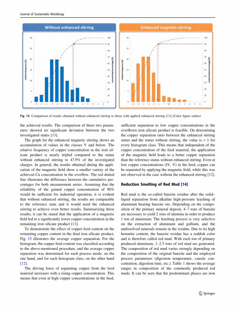
the achieved results. The comparison of these two param-
eters showed no significant deviation between the two
investigated states [13].
The graph for the enhanced magnetic stirring shows an
accumulation of values in the classes V and below. The
relative frequency of copper concentration in the iron sil-
icate product is nearly tripled compared to the status
without enhanced stirring to 47.9% of the investigated
charges. In general, the results obtained during the appli-
cation of the magnetic field show a smaller variety of the
achieved Cu concentration in the overflow. The red dotted
line illustrates the difference between the cumulative per-
centages for both measurement series. Assuming that the
reliability of the gained copper concentration of 90%
would be sufficient for industrial operation, it is evident
that without enhanced stirring, the results are comparable
to the reference state and it would need the enhanced
stirring to achieve even better results. Summarizing these
results, it can be stated that the application of a magnetic
field led to a significantly lower copper concentration in the
remaining iron silicate product [13].
To demonstrate the effect of copper feed content on the
remaining copper content in the final iron silicate product,
Fig. 15 illustrates the average copper separation. For the
histogram, the copper feed content was classified according
to the above-mentioned procedure, and the average copper
separation was determined for each process mode, on the
one hand, and for each histogram class, on the other hand
[12].
The driving force of separating copper from the feed
material increases with a rising copper concentration. This
means that even at high copper concentrations in the feed,
sufficient separation to low copper concentrations in the
overflown iron silicate product is feasible. On determining
the copper separation ratio between the enhanced stirring
status and the status without stirring, the value is[ 1 for
every histogram class. This means that independent of the
copper concentration of the feed material, the application
of the magnetic field leads to a better copper separation
than the reference status without enhanced stirring. Even at
low copper concentrations (IV, V) in the feed, copper can
be separated by applying the magnetic field, while this was
not observed in the case without the enhanced stirring [12].
Reduction Smelting of Red Mud [14]
Red mud is the so-called bauxite residue after the solid–
liquid separation from alkaline high-pressure leaching of
aluminum bearing bauxite ore. Depending on the compo-
sition of the primary mineral deposit, 4–7 tons of bauxite
are necessary to yield 2 tons of alumina in order to produce
1 ton of aluminum. The leaching process is very selective
on the extraction of aluminum and gallium, and the
undissolved minerals remain in the residue. Due to its high
hematite content, the bauxite residue has a reddish color
and is therefore called red mud. With each ton of primary
produced aluminum, 1–2.5 tons of red mud are generated.
The composition of red mud varies strongly depending on
the composition of the original bauxite and the employed
process parameters (digestion temperature, caustic con-
centration, digestion time, etc.). Table 1 shows the average
ranges in composition of the commonly produced red
muds. It can be seen that the predominant phases are iron
Fig. 14 Comparison of results obtained without enhanced stirring to those with applied enhanced stirring [13] (Color figure online)
Journal of Sustainable Metallurgy
123
compounds like hematite or goethite which can be easily
recovered by carbothermic reduction.
The examined red mud comes from the landfill of the
former ‘‘Vereinigte Aluminiumwerke’’ near Lunen, Ger-
many. The original composition is shown in Table 1, and
indicates high amounts of remaining alumina. In former
times, high throughputs and cheap but poorly digestible
bauxites as raw material did not lead to high alumina
recovery. Therefore, X-ray diffraction patterns show the
predominant phases are hematite and still aluminum
hydroxides (gibbsite and boehmite). The exact aluminum
content is measured by X-ray fluorescence, and the alu-
minum values in Table 1 are converted into alumina as
quite commonly described in literature. The sum of all
components does not make up 100%. This original red mud
from landfill is one material for the following test trials.
Moreover, the entire research project includes a recov-
ery of the maximum amount of the remaining alumina
content. Therefore, the red mud from the landfill is leached
a second time employing the Bayer process with optimized
parameters. From this second leaching originates a red mud
with the composition called after ‘‘re-leaching’’ (see
Table 1) which is also examined for iron recovery.
The third examined raw material for carbothermic iron
recovery experiments is presented in the last column of
Table 1. In this case, small amounts of lime are added
during the second leaching of the initial red mud in order to
increase the recovery of alumina in the leaching step.
Experiments confirmed an increased alumina yield of about
10% since the molar ratio CaO/SiO2 increased from 0.31 in
the initial red mud to 0.5 by the addition of lime. Thus, the
remaining leaching residue is increased in its lime content,
while the other constituents are slightly diluted.
Theoretical Considerations
It can be seen from Fig. 16 that the hematite is first reduced
to FeO. At about 15 g carbon addition, the co-reduction of
titania to Ti2O3 starts but stagnates at a low level. Only
15–35% of the titania is reduced to Ti2O3. By adding 26 g
Fig. 15 Comparison of results
obtained without enhanced
stirring to those with applied
enhanced stirring [12] (Color
figure online)
Table 1 Compositions of different red muds and composition of the raw material used in the experiments
Component in wt% Average red mud Red mud Lunen (Germany) After re-leaching After re-leaching with CaO (CaO/SiO2 * 0.5)
Fe2O3 30–50 29.5 35.5 34.7
Al2O3 10–20 27 18.3 17.7
SiO2 5–20 13.1 14.9 15
TiO2 3–15 8 9.3 9
Na2O 3–7 7 9.3 9.1
CaO 1–8 3.8 4.7 7.7
Cr2O3 – 0.35 0.41 0.4
P2O5 – 0.22 0.25 0.27
SO3 – 0.47 0.5 0.58
Journal of Sustainable Metallurgy
123
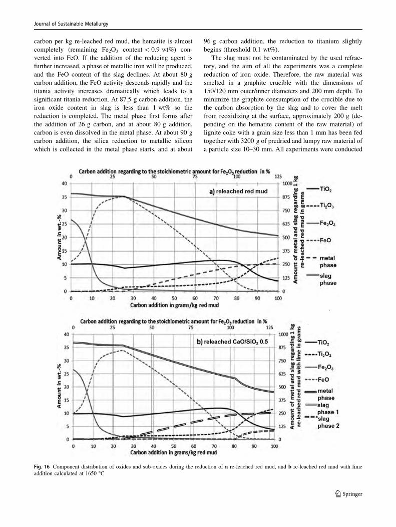
carbon per kg re-leached red mud, the hematite is almost
completely (remaining Fe2O3 content\ 0.9 wt%) con-
verted into FeO. If the addition of the reducing agent is
further increased, a phase of metallic iron will be produced,
and the FeO content of the slag declines. At about 80 g
carbon addition, the FeO activity descends rapidly and the
titania activity increases dramatically which leads to a
significant titania reduction. At 87.5 g carbon addition, the
iron oxide content in slag is less than 1 wt% so the
reduction is completed. The metal phase first forms after
the addition of 26 g carbon, and at about 80 g addition,
carbon is even dissolved in the metal phase. At about 90 g
carbon addition, the silica reduction to metallic silicon
which is collected in the metal phase starts, and at about
96 g carbon addition, the reduction to titanium slightly
begins (threshold 0.1 wt%).
The slag must not be contaminated by the used refrac-
tory, and the aim of all the experiments was a complete
reduction of iron oxide. Therefore, the raw material was
smelted in a graphite crucible with the dimensions of
150/120 mm outer/inner diameters and 200 mm depth. To
minimize the graphite consumption of the crucible due to
the carbon absorption by the slag and to cover the melt
from reoxidizing at the surface, approximately 200 g (de-
pending on the hematite content of the raw material) of
lignite coke with a grain size less than 1 mm has been fed
together with 3200 g of predried and lumpy raw material of
a particle size 10–30 mm. All experiments were conducted
Fig. 16 Component distribution of oxides and sub-oxides during the reduction of a re-leached red mud, and b re-leached red mud with lime
addition calculated at 1650 �C
Journal of Sustainable Metallurgy
123
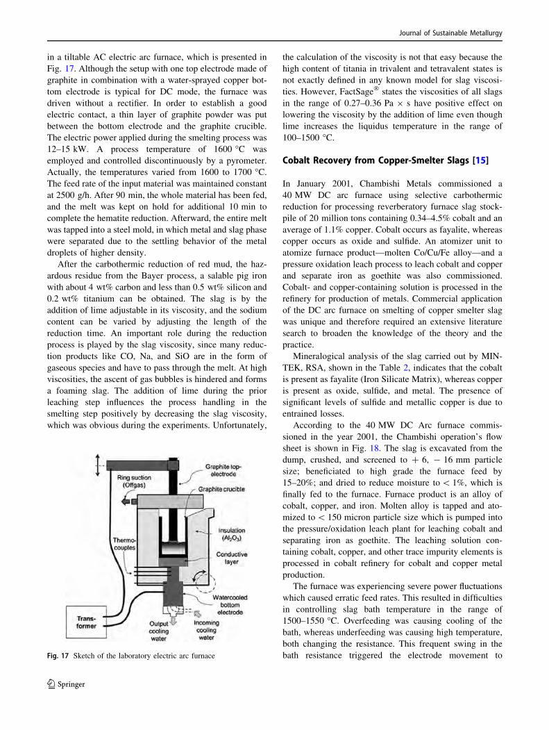
in a tiltable AC electric arc furnace, which is presented in
Fig. 17. Although the setup with one top electrode made of
graphite in combination with a water-sprayed copper bot-
tom electrode is typical for DC mode, the furnace was
driven without a rectifier. In order to establish a good
electric contact, a thin layer of graphite powder was put
between the bottom electrode and the graphite crucible.
The electric power applied during the smelting process was
12–15 kW. A process temperature of 1600 �C was
employed and controlled discontinuously by a pyrometer.
Actually, the temperatures varied from 1600 to 1700 �C.The feed rate of the input material was maintained constant
at 2500 g/h. After 90 min, the whole material has been fed,
and the melt was kept on hold for additional 10 min to
complete the hematite reduction. Afterward, the entire melt
was tapped into a steel mold, in which metal and slag phase
were separated due to the settling behavior of the metal
droplets of higher density.
After the carbothermic reduction of red mud, the haz-
ardous residue from the Bayer process, a salable pig iron
with about 4 wt% carbon and less than 0.5 wt% silicon and
0.2 wt% titanium can be obtained. The slag is by the
addition of lime adjustable in its viscosity, and the sodium
content can be varied by adjusting the length of the
reduction time. An important role during the reduction
process is played by the slag viscosity, since many reduc-
tion products like CO, Na, and SiO are in the form of
gaseous species and have to pass through the melt. At high
viscosities, the ascent of gas bubbles is hindered and forms
a foaming slag. The addition of lime during the prior
leaching step influences the process handling in the
smelting step positively by decreasing the slag viscosity,
which was obvious during the experiments. Unfortunately,
the calculation of the viscosity is not that easy because the
high content of titania in trivalent and tetravalent states is
not exactly defined in any known model for slag viscosi-
ties. However, FactSage� states the viscosities of all slags
in the range of 0.27–0.36 Pa 9 s have positive effect on
lowering the viscosity by the addition of lime even though
lime increases the liquidus temperature in the range of
100–1500 �C.
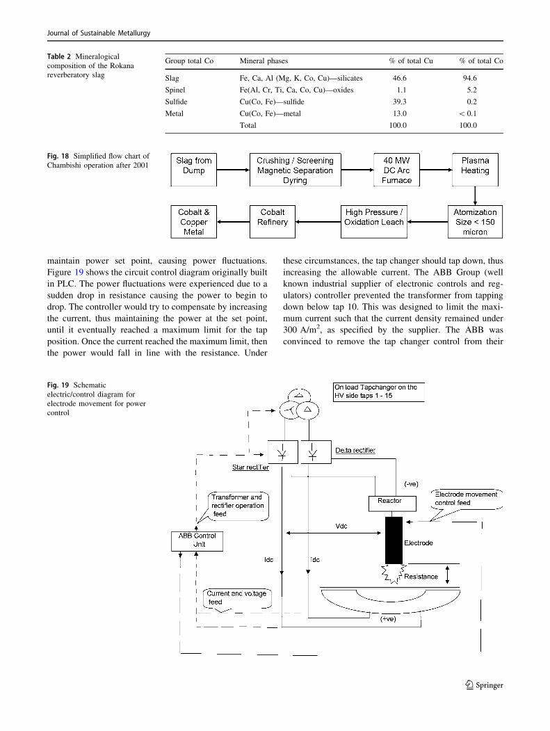
Cobalt Recovery from Copper-Smelter Slags [15]
In January 2001, Chambishi Metals commissioned a
40 MW DC arc furnace using selective carbothermic
reduction for processing reverberatory furnace slag stock-
pile of 20 million tons containing 0.34–4.5% cobalt and an
average of 1.1% copper. Cobalt occurs as fayalite, whereas
copper occurs as oxide and sulfide. An atomizer unit to
atomize furnace product—molten Co/Cu/Fe alloy—and a
pressure oxidation leach process to leach cobalt and copper
and separate iron as goethite was also commissioned.
Cobalt- and copper-containing solution is processed in the
refinery for production of metals. Commercial application
of the DC arc furnace on smelting of copper smelter slag
was unique and therefore required an extensive literature
search to broaden the knowledge of the theory and the
practice.
Mineralogical analysis of the slag carried out by MIN-
TEK, RSA, shown in the Table 2, indicates that the cobalt
is present as fayalite (Iron Silicate Matrix), whereas copper
is present as oxide, sulfide, and metal. The presence of
significant levels of sulfide and metallic copper is due to
entrained losses.
According to the 40 MW DC Arc furnace commis-
sioned in the year 2001, the Chambishi operation’s flow
sheet is shown in Fig. 18. The slag is excavated from the
dump, crushed, and screened to ? 6, - 16 mm particle
size; beneficiated to high grade the furnace feed by
15–20%; and dried to reduce moisture to\ 1%, which is
finally fed to the furnace. Furnace product is an alloy of
cobalt, copper, and iron. Molten alloy is tapped and ato-
mized to\ 150 micron particle size which is pumped into
the pressure/oxidation leach plant for leaching cobalt and
separating iron as goethite. The leaching solution con-
taining cobalt, copper, and other trace impurity elements is
processed in cobalt refinery for cobalt and copper metal
production.
The furnace was experiencing severe power fluctuations
which caused erratic feed rates. This resulted in difficulties
in controlling slag bath temperature in the range of
1500–1550 �C. Overfeeding was causing cooling of the
bath, whereas underfeeding was causing high temperature,
both changing the resistance. This frequent swing in the
bath resistance triggered the electrode movement toFig. 17 Sketch of the laboratory electric arc furnace
Journal of Sustainable Metallurgy
123
maintain power set point, causing power fluctuations.
Figure 19 shows the circuit control diagram originally built
in PLC. The power fluctuations were experienced due to a
sudden drop in resistance causing the power to begin to
drop. The controller would try to compensate by increasing
the current, thus maintaining the power at the set point,
until it eventually reached a maximum limit for the tap
position. Once the current reached the maximum limit, then
the power would fall in line with the resistance. Under
these circumstances, the tap changer should tap down, thus
increasing the allowable current. The ABB Group (well
known industrial supplier of electronic controls and reg-
ulators) controller prevented the transformer from tapping
down below tap 10. This was designed to limit the maxi-
mum current such that the current density remained under
300 A/m2, as specified by the supplier. The ABB was
convinced to remove the tap changer control from their
Fig. 18 Simplified flow chart of
Chambishi operation after 2001
Fig. 19 Schematic
electric/control diagram for
electrode movement for power
control
Table 2 Mineralogical
composition of the Rokana
reverberatory slag
Group total Co Mineral phases % of total Cu % of total Co
Slag Fe, Ca, Al (Mg, K, Co, Cu)—silicates 46.6 94.6
Spinel Fe(Al, Cr, Ti, Ca, Co, Cu)—oxides 1.1 5.2
Sulfide Cu(Co, Fe)—sulfide 39.3 0.2
Metal Cu(Co, Fe)—metal 13.0 \ 0.1
Total 100.0 100.0
Journal of Sustainable Metallurgy
123
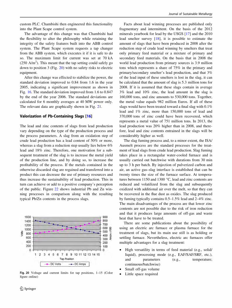
custom PLC. Chambishi then engineered this functionality
into the Plant Scape control system.
The advantage of this change was that Chambishi had
the flexibility to alter the philosophy while retaining the
integrity of the safety features built into the ABB control
system. The Plant Scape system requests a tap changer
from the ABB system, which executes it if it is safe to do
so. The maximum limit for current was set at 70 kA
(250 A/m2). This meant that the tap setting could safely go
down to position 3 (Fig. 20) with no safety risks to electric
equipment.
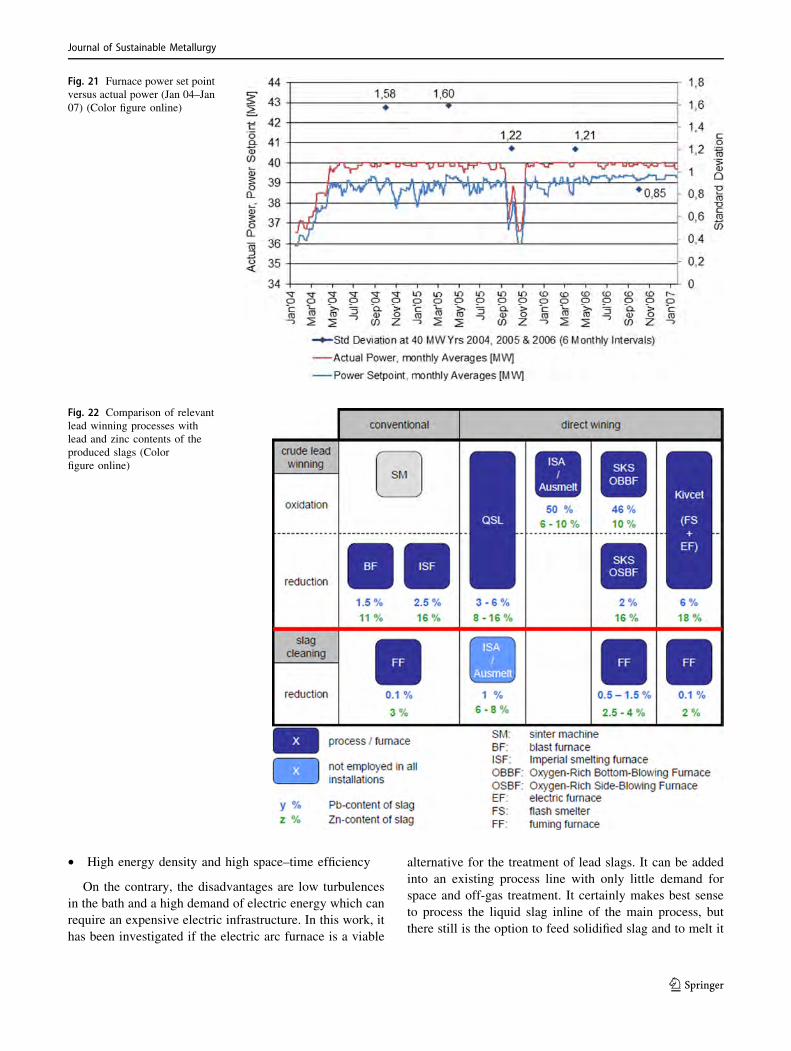
After this change was effected to stabilize the power, the
standard deviation improved to 0.84 from 1.6 in the year
2005, indicating a significant improvement as shown in
Fig. 16. The standard deviation improved from 1.6 to 0.847
by the end of the year 2006. The standard deviations are
calculated for 6 monthly averages at 40 MW power only.
The relevant data are graphically shown in Fig. 21.
Valorization of Pb-Containing Slags [16]
The lead and zinc contents of slags from lead production
vary depending on the type of the production process and
the process parameters. A slag from an oxidation step of
crude lead production has a lead content of 50% or more,
whereas a slag from a reduction step usually lies below 6%
lead and 18% zinc. Therefore, one motivation for a sub-
sequent treatment of the slag is to increase the metal yield
of the production line, and by doing so, to increase the
profitability of the process. If the metals contained in the
otherwise discarded slag are regained and transferred into a
product this can decrease the use of primary resources and
thus increase the sustainability of lead production. This in
turn can achieve or add to a positive company’s perception
of the public. Figure 22 shows industrial Pb and Zn win-
ning processes in comparison along with the resulting
typical Pb/Zn contents in the process slags.
Facts about lead winning processes are published only
fragmentary and intermittent. On the basis of the 2012
minerals yearbook for lead by the USGS [17] and the 2010
lead smelter survey [18], it is possible to estimate the
amount of slags that have been produced in 2008 after the
reduction step of crude lead winning by smelters that treat
only primary feed material or a mixture of primary and
secondary feed materials. On the basis that in 2008 the
world lead production from primary sources is 3.9 million
tons which represents a share of 75% in the primary and
primary/secondary smelter’s lead production, and that 3%
of the lead input of these smelters is lost in the slag, it can
be calculated that the amount of slag is 5.3 million tons for
2008. If it is assumed that these slags contain in average
3% lead and 10% zinc, the lead amount in the slag is
160,000 tons, and zinc amounts to 530,000 tons. Together,
the metal value equals 982 million Euros. If all of these
slags would have been treated toward a final slag with 0.1%
lead and 1% zinc, more than 150,000 tons of lead and
370,000 tons of zinc could have been recovered, which
represents a metal value of 751 million tons. In 2013, the
lead production was 20% higher than in 2008, and there-
fore, lead and zinc contents entrained in the slags will be
considerably higher as well.
The slag fuming process and, to a minor extent, the ISA/
Ausmelt process are the standard processes for the treat-
ment of lead slags from crude lead production. Slag fuming
takes place in a rectangular water-cooled furnace and is
usually carried out batchwise with durations from 30 min
up to 3 h per batch. By injection of pulverized carbon and
air, an active gas–slag interface is established that can be
twenty times the size of the furnace surface. At tempera-
tures between 1150 and 1300 �C, lead and zinc contents arereduced and volatilized from the slag and subsequently
oxidized with additional air over the melt, so that they can
be recovered in the flue dust as oxides. The slag produced
by fuming typically contains 0.5–1.5% lead and 2–4% zinc.
The main disadvantages of the process are that lower zinc
contents are not possible due to the risk of iron reduction
and that it produces large amounts of off-gas and waste
heat that have to be treated.
There are some publications about the possibility of
using an electric arc furnace or plasma furnace for the
treatment of slags, but its main use still is as holding or
settling furnace. Nevertheless, electric arc furnaces offer
multiple advantages for a slag treatment:
• High versatility in terms of feed material (e.g., solid/
liquid), processing mode (e.g., EAF/SAF/SRF, etc.),
and parameters (e.g., temperature;
continuous/batchwise)
• Small off-gas volume
• Little space requiredFig. 20 Voltage and current limits for tap positions, 1–15 (Color
figure online)
Journal of Sustainable Metallurgy
123
• High energy density and high space–time efficiency
On the contrary, the disadvantages are low turbulences
in the bath and a high demand of electric energy which can
require an expensive electric infrastructure. In this work, it
has been investigated if the electric arc furnace is a viable
alternative for the treatment of lead slags. It can be added
into an existing process line with only little demand for
space and off-gas treatment. It certainly makes best sense
to process the liquid slag inline of the main process, but
there still is the option to feed solidified slag and to melt it
Fig. 21 Furnace power set point
versus actual power (Jan 04–Jan
07) (Color figure online)
Fig. 22 Comparison of relevant
lead winning processes with
lead and zinc contents of the
produced slags (Color
figure online)
Journal of Sustainable Metallurgy
123
before treatment, too. In any case, the electric arc furnace is
able to adjust the slag temperature as needed. It is possible
to generate stronger reducing conditions than in the slag
fuming process, because if iron is reduced to metallic state,
it can be molten and consumed as reducing agent. This
should enable the electric arc furnace to produce slags
which are low both in lead and zinc.
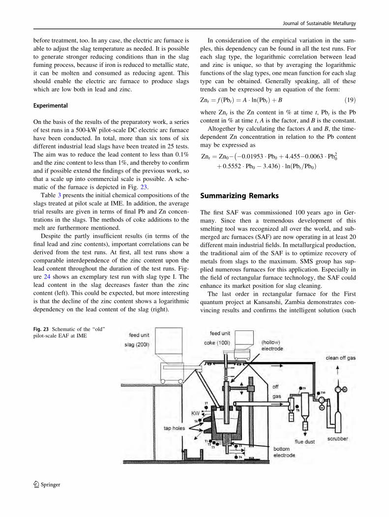
Experimental
On the basis of the results of the preparatory work, a series
of test runs in a 500-kW pilot-scale DC electric arc furnace
have been conducted. In total, more than six tons of six
different industrial lead slags have been treated in 25 tests.
The aim was to reduce the lead content to less than 0.1%
and the zinc content to less than 1%, and thereby to confirm
and if possible extend the findings of the previous work, so
that a scale up into commercial scale is possible. A sche-
matic of the furnace is depicted in Fig. 23.
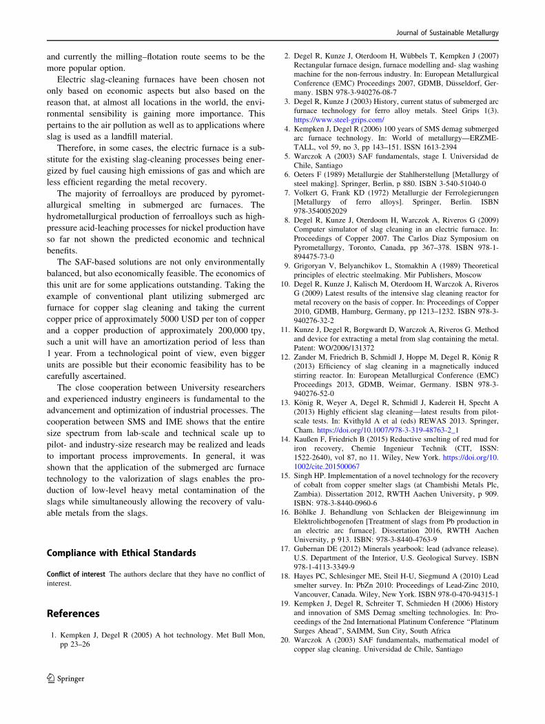
Table 3 presents the initial chemical compositions of the
slags treated at pilot scale at IME. In addition, the average
trial results are given in terms of final Pb and Zn concen-
trations in the slags. The methods of coke additions to the
melt are furthermore mentioned.
Despite the partly insufficient results (in terms of the
final lead and zinc contents), important correlations can be
derived from the test runs. At first, all test runs show a
comparable interdependence of the zinc content upon the
lead content throughout the duration of the test runs. Fig-
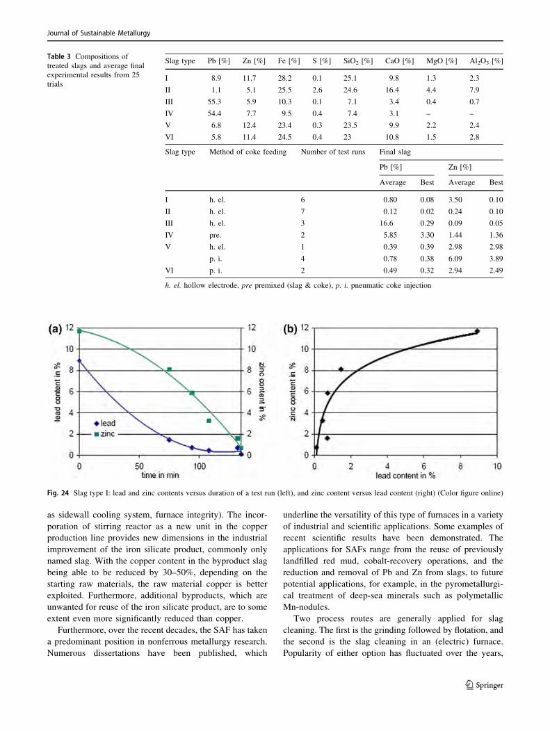
ure 24 shows an exemplary test run with slag type I. The
lead content in the slag decreases faster than the zinc
content (left). This could be expected, but more interesting
is that the decline of the zinc content shows a logarithmic
dependency on the lead content of the slag (right).
In consideration of the empirical variation in the sam-
ples, this dependency can be found in all the test runs. For
each slag type, the logarithmic correlation between lead
and zinc is unique, so that by averaging the logarithmic
functions of the slag types, one mean function for each slag
type can be obtained. Generally speaking, all of these
trends can be expressed by an equation of the form:
Znt ¼ f Pbtð Þ ¼ A � ln Pbtð Þ þ B ð19Þ
where Znt is the Zn content in % at time t, Pbt is the Pb
content in % at time t, A is the factor, and B is the constant.
Altogether by calculating the factors A and B, the time-
dependent Zn concentration in relation to the Pb content
may be expressed as
Znt ¼ Zn0� �0:01953 � Pb0 þ 4:455�0:0063 � Pb20�
þ 0:5552 � Pb0 � 3:436Þ � ln Pbt=Pb0ð Þ
Summarizing Remarks
The first SAF was commissioned 100 years ago in Ger-
many. Since then a tremendous development of this
smelting tool was recognized all over the world, and sub-
merged arc furnaces (SAF) are now operating in at least 20
different main industrial fields. In metallurgical production,
the traditional aim of the SAF is to optimize recovery of
metals from slags to the maximum. SMS group has sup-
plied numerous furnaces for this application. Especially in
the field of rectangular furnace technology, the SAF could
enhance its market position for slag cleaning.
The last order in rectangular furnace for the First
quantum project at Kansanshi, Zambia demonstrates con-
vincing results and confirms the intelligent solution (such
Fig. 23 Schematic of the ‘‘old’’
pilot-scale EAF at IME
Journal of Sustainable Metallurgy
123
as sidewall cooling system, furnace integrity). The incor-
poration of stirring reactor as a new unit in the copper
production line provides new dimensions in the industrial
improvement of the iron silicate product, commonly only
named slag. With the copper content in the byproduct slag
being able to be reduced by 30–50%, depending on the
starting raw materials, the raw material copper is better
exploited. Furthermore, additional byproducts, which are
unwanted for reuse of the iron silicate product, are to some
extent even more significantly reduced than copper.
Furthermore, over the recent decades, the SAF has taken
a predominant position in nonferrous metallurgy research.
Numerous dissertations have been published, which
underline the versatility of this type of furnaces in a variety
of industrial and scientific applications. Some examples of
recent scientific results have been demonstrated. The
applications for SAFs range from the reuse of previously
landfilled red mud, cobalt-recovery operations, and the
reduction and removal of Pb and Zn from slags, to future
potential applications, for example, in the pyrometallurgi-
cal treatment of deep-sea minerals such as polymetallic
Mn-nodules.
Two process routes are generally applied for slag
cleaning. The first is the grinding followed by flotation, and
the second is the slag cleaning in an (electric) furnace.
Popularity of either option has fluctuated over the years,
Fig. 24 Slag type I: lead and zinc contents versus duration of a test run (left), and zinc content versus lead content (right) (Color figure online)
Table 3 Compositions of
treated slags and average final
experimental results from 25
trials
Slag type Pb [%] Zn [%] Fe [%] S [%] SiO2 [%] CaO [%] MgO [%] Al2O3 [%]
I 8.9 11.7 28.2 0.1 25.1 9.8 1.3 2.3
II 1.1 5.1 25.5 2.6 24.6 16.4 4.4 7.9
III 55.3 5.9 10.3 0.1 7.1 3.4 0.4 0.7
IV 54.4 7.7 9.5 0.4 7.4 3.1 – –
V 6.8 12.4 23.4 0.3 23.5 9.9 2.2 2.4
VI 5.8 11.4 24.5 0.4 23 10.8 1.5 2.8
Slag type Method of coke feeding Number of test runs Final slag
Pb [%] Zn [%]
Average Best Average Best
I h. el. 6 0.80 0.08 3.50 0.10
II h. el. 7 0.12 0.02 0.24 0.10
III h. el. 3 16.6 0.29 0.09 0.05
IV pre. 2 5.85 3.30 1.44 1.36
V h. el. 1 0.39 0.39 2.98 2.98
p. i. 4 0.78 0.38 6.09 3.89
VI p. i. 2 0.49 0.32 2.94 2.49
h. el. hollow electrode, pre premixed (slag & coke), p. i. pneumatic coke injection
Journal of Sustainable Metallurgy
123
and currently the milling–flotation route seems to be the
more popular option.
Electric slag-cleaning furnaces have been chosen not
only based on economic aspects but also based on the
reason that, at almost all locations in the world, the envi-
ronmental sensibility is gaining more importance. This
pertains to the air pollution as well as to applications where
slag is used as a landfill material.
Therefore, in some cases, the electric furnace is a sub-
stitute for the existing slag-cleaning processes being ener-
gized by fuel causing high emissions of gas and which are
less efficient regarding the metal recovery.
The majority of ferroalloys are produced by pyromet-
allurgical smelting in submerged arc furnaces. The
hydrometallurgical production of ferroalloys such as high-
pressure acid-leaching processes for nickel production have
so far not shown the predicted economic and technical
benefits.
The SAF-based solutions are not only environmentally
balanced, but also economically feasible. The economics of
this unit are for some applications outstanding. Taking the
example of conventional plant utilizing submerged arc
furnace for copper slag cleaning and taking the current
copper price of approximately 5000 USD per ton of copper
and a copper production of approximately 200,000 tpy,
such a unit will have an amortization period of less than
1 year. From a technological point of view, even bigger
units are possible but their economic feasibility has to be
carefully ascertained.
The close cooperation between University researchers
and experienced industry engineers is fundamental to the
advancement and optimization of industrial processes. The
cooperation between SMS and IME shows that the entire
size spectrum from lab-scale and technical scale up to
pilot- and industry-size research may be realized and leads
to important process improvements. In general, it was
shown that the application of the submerged arc furnace
technology to the valorization of slags enables the pro-
duction of low-level heavy metal contamination of the
slags while simultaneously allowing the recovery of valu-
able metals from the slags.
Compliance with Ethical Standards
Conflict of interest The authors declare that they have no conflict of
interest.
References
1. Kempken J, Degel R (2005) A hot technology. Met Bull Mon,
pp 23–26
2. Degel R, Kunze J, Oterdoom H, Wubbels T, Kempken J (2007)
Rectangular furnace design, furnace modelling and- slag washing
machine for the non-ferrous industry. In: European Metallurgical
Conference (EMC) Proceedings 2007, GDMB, Dusseldorf, Ger-
many. ISBN 978-3-940276-08-7
3. Degel R, Kunze J (2003) History, current status of submerged arc
furnace technology for ferro alloy metals. Steel Grips 1(3).
https://www.steel-grips.com/
4. Kempken J, Degel R (2006) 100 years of SMS demag submerged
arc furnace technology. In: World of metallurgy—ERZME-
TALL, vol 59, no 3, pp 143–151. ISSN 1613-2394
5. Warczok A (2003) SAF fundamentals, stage I. Universidad de
Chile, Santiago
6. Oeters F (1989) Metallurgie der Stahlherstellung [Metallurgy of
steel making]. Springer, Berlin, p 880. ISBN 3-540-51040-0
7. Volkert G, Frank KD (1972) Metallurgie der Ferrolegierungen
[Metallurgy of ferro alloys]. Springer, Berlin. ISBN
978-3540052029
8. Degel R, Kunze J, Oterdoom H, Warczok A, Riveros G (2009)
Computer simulator of slag cleaning in an electric furnace. In:
Proceedings of Copper 2007. The Carlos Diaz Symposium on
Pyrometallurgy, Toronto, Canada, pp 367–378. ISBN 978-1-
894475-73-0
9. Grigoryan V, Belyanchikov L, Stomakhin A (1989) Theoretical
principles of electric steelmaking. Mir Publishers, Moscow
10. Degel R, Kunze J, Kalisch M, Oterdoom H, Warczok A, Riveros
G (2009) Latest results of the intensive slag cleaning reactor for
metal recovery on the basis of copper. In: Proceedings of Copper
2010, GDMB, Hamburg, Germany, pp 1213–1232. ISBN 978-3-
940276-32-2
11. Kunze J, Degel R, Borgwardt D, Warczok A, Riveros G. Method
and device for extracting a metal from slag containing the metal.
Patent: WO/2006/131372
12. Zander M, Friedrich B, Schmidl J, Hoppe M, Degel R, Konig R
(2013) Efficiency of slag cleaning in a magnetically induced
stirring reactor. In: European Metallurgical Conference (EMC)
Proceedings 2013, GDMB, Weimar, Germany. ISBN 978-3-
940276-52-0
13. Konig R, Weyer A, Degel R, Schmidl J, Kadereit H, Specht A
(2013) Highly efficient slag cleaning—latest results from pilot-
scale tests. In: Kvithyld A et al (eds) REWAS 2013. Springer,
Cham. https://doi.org/10.1007/978-3-319-48763-2_1
14. Kaußen F, Friedrich B (2015) Reductive smelting of red mud for
iron recovery, Chemie Ingenieur Technik (CIT, ISSN:
1522-2640), vol 87, no 11. Wiley, New York. https://doi.org/10.
1002/cite.201500067
15. Singh HP. Implementation of a novel technology for the recovery
of cobalt from copper smelter slags (at Chambishi Metals Plc,
Zambia). Dissertation 2012, RWTH Aachen University, p 909.
ISBN: 978-3-8440-0960-6
16. Bohlke J. Behandlung von Schlacken der Bleigewinnung im
Elektrolichtbogenofen [Treatment of slags from Pb production in
an electric arc furnace]. Dissertation 2016, RWTH Aachen
University, p 913. ISBN: 978-3-8440-4763-9
17. Gubernan DE (2012) Minerals yearbook: lead (advance release).
U.S. Department of the Interior, U.S. Geological Survey. ISBN
978-1-4113-3349-9
18. Hayes PC, Schlesinger ME, Steil H-U, Siegmund A (2010) Lead
smelter survey. In: PbZn 2010: Proceedings of Lead-Zinc 2010,
Vancouver, Canada. Wiley, New York. ISBN 978-0-470-94315-1
19. Kempken J, Degel R, Schreiter T, Schmieden H (2006) History
and innovation of SMS Demag smelting technologies. In: Pro-
ceedings of the 2nd International Platinum Conference ‘‘Platinum
Surges Ahead’’, SAIMM, Sun City, South Africa
20. Warczok A (2003) SAF fundamentals, mathematical model of
copper slag cleaning. Universidad de Chile, Santiago
Journal of Sustainable Metallurgy
123