Embed Size (px)
Citation preview
E SAND-PAINTER: Two-dimensional powder deposition
Joseph PegnaStephane Pattofatto, Raphael Berge,
Carol Bangalan, Henry Herring,Mathias LeSaux, Jason Engler
Department of Mechanical Engineering, Concordia UniversityMontreal, Quebec H3G1M8, Canada
Tel: (514) 848-4193 Fax: (514) 848-3175email: [email protected]
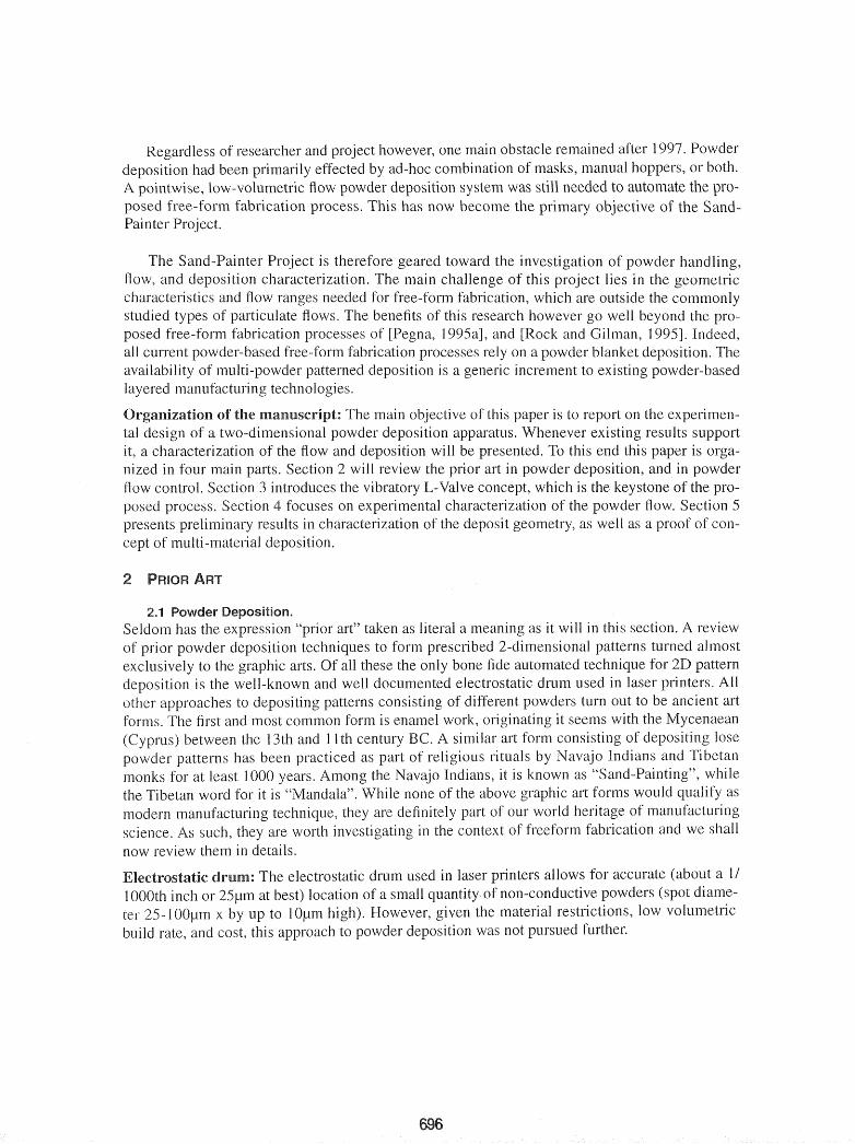
Abstract: The Sand-Painter project addresses the problem ofpointwise deposition ofmulti-material powders in layered manufacturing. This approach is key to the development of selectiveaggregation processes capable ofproducing functional prototypes with internal sub-structures notachievable by any of the extant layered manufacturing processes. The solution adopted for thisproject is an automated version of the ancient Native American art of sand painting. Preliminaryresults pertaining to powder flow and deposition characterization are presented. A proof of concept multi-material deposition process was demonstrated.
Keywords: Sand painting, layered manufacturing, SLS, 3D-Printing, selective aggregation,multi-material, multi-modal structures, functionally graded materials., mechatronics.
1 OF THE SAND-PAINTER PROJECT
The Sand-Painter Project is the extension of a long-term, low-budget undergraduate researchsupervised by the lead author between 1993 and 1997 [Pegna, 1995a],[Pegna, 1995b],[Pegna,1997]. The main objective of this project was a low-cost investigation and evaluation of the avenues left unexplored in the Solid Freeform Fabrication community, especially as they pertain tothe fabrication of large, multi-material, functional prototypes from bulk material.
For more details on the rationale and methodology of the preliminary research, the reader isreferred to the 1995 Solid Freeform Fabrication Proceedings [Pegna, 1995a]. The main outcomeof this and other [Rock and Gilman, 1995] works was a proof of concept that patterned depositionof powder layers can be used as the basis for free-form fabrication. Two other important predictions came out of [Pegna, 1995a]. First it showed that the proposed approach lends itself to thefabrication of multi-material structures by either processing multiple powders in a single layer, orby inclusion of prefabricated sub-structures. Second, the volumetric flowrates experimentally feasible were compatible with the fabrication of large functional structures, and made the technologya viable alternative for construction automation.
An incidental result came from the low-cost constraint which led to the choice of cement andsand as the building materials. The processing of each patterned layer with water vapor resulted ina concrete with unusual and anisotropic material properties [Pegna, 1997]. Though these resultswould need to be confirmed by repeating the experiment, they illustrate the potential of multipowder processes in the creation of hitherto undiscovered material properties.
jI)I).:) JUSl'ph Pcgllil. printl'd with p~rJl1issioll
695
Regardless of researcher and project however, one main obstacle remained after 1997. Powderdeposition had been primarily effected by ad-hoc combination of masks, manual hoppers, or both.A pointwise, low-volumetric flow powder deposition system was still needed to automate the proposed free-form fabrication process. This has now become the primary objective of the SandPainter Project.
The Sand-Painter Project is therefore geared toward the investigation of powder handling,flow, and deposition characterization. The main challenge of this project lies in the geometriccharacteristics and flow ranges needed for free-form fabrication, which are outside the commonlystudied types of particulate flows. The benefits of this research however go well beyond the proposed free-form fabrication processes of [Pegna, I 995aJ, and [Rock and Gilman, 1995]. Indeed,all current powder-based free-form fabrication processes rely on a powder blanket deposition. Theavailability of multi-powder patterned deposition is a generic increment to existing powder-basedlayered manufacturing technologies.
)n:!:aniz3lti(]ln of the The main objective of this paper is to report on the experimen-tal design of a two-dimensional powder deposition apparatus. Whenever existing results supportit, a characterization of the flow and deposition will be presented. To this end this paper is organized in four main parts. Section 2 will review the prior art in powder deposition, and in powderflow control. Section 3 introduces the vibratory L-Valve concept, which is the keystone of the proposed process. Section 4 focuses on experimental characterization of the powder flow. Section 5presents preliminary results in characterization of the deposit geometry, as well as a proof of concept of multi-material deposition.
2.1 Powder n ................. "',;+ .........
Seldom has the expression "prior art" taken as literal a meaning as it will in this section. A reviewof powder deposition techniques to form prescribed 2-dimensional patterns turned almostexclusively to the graphic arts. Of all these the only bone fide automated technique for 2D patterndeposition is the well-known and well documented electrostatic drum used in laser printers. Allother approaches to depositing patterns consisting of ditlerent powders turn out to be ancient artforms. The first and most common form is enamel work, originating it seems with the Mycenaean(Cyprus) between the 13th and 11 th century BC. A similar art form consisting of depositing losepowder patterns has been practiced as part of religious rituals by Navajo Indians and Tibetanmonks for at least 1000 years. Among the Navajo Indians, it is known as "Sand-Painting", whilethe Tibetan word for it is "Mandala". While none of the above graphic art forms would qualify asmodern manufacturing technique, they are definitely part of our world heritage of manufacturingscience. As such, they are worth investigating in the context of freeform fabrication and we shallnow review them in details.
lectro,st3ltic drum: The electrostatic drum used in laser printers allows for accurate (about a 1/1000th inch or 25~m at best) location of a small quantity of non-conductive powders (spot diameter 25-] OO~m x by up to 1O~m high). However, given the material restrictions, low volumetricbuild rate, and cost, this approach to powder deposition was not pursued further.
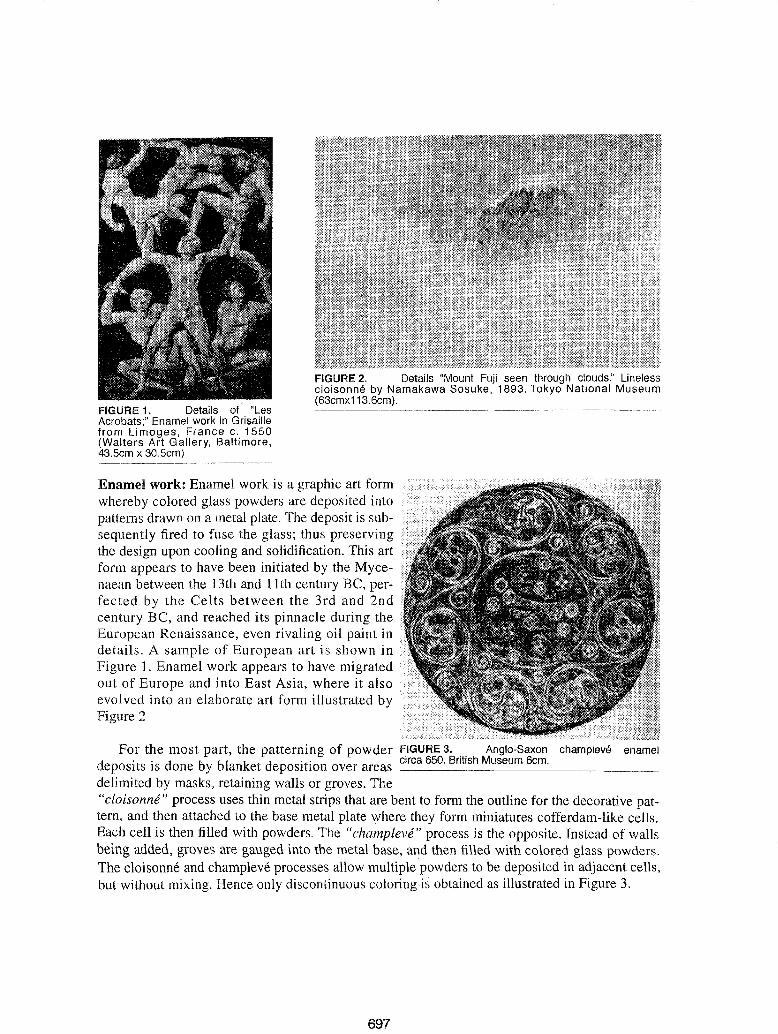
FIGURE 1. Details of "LesAcrobats;" Enamel work in Grisaillefrom Limoges, France c. 1550(Walters Art Gallery, Baltimore,43.5cm x 30.5cm)
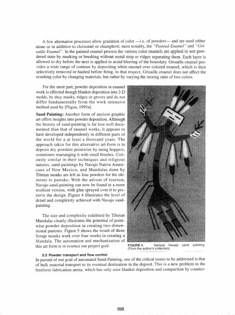
FIGURE 2. Details "Mount Fuji seen through clouds." Linelesscloisonne by Namakawa Sosuke, 1893. Tokyo National Museum(63cmx113.6cm).
Enamel work: Enamel work is a graphic art formwhereby colored glass powders are deposited intopatterns drawn on a metal plate. The deposit is subsequently fired to fuse the glass; thus preservingthe design upon cooling and solidification. This artform appears to have been initiated by the Mycenaean between the 13th and 11th century BC, perfected by the Celts between the 3rd and 2ndcentury BC, and reached its pinnacle during theEuropean Renaissance, even rivaling oil paint indetails. A sample of European art is shown inFigure 1. Enamel work appears to have migratedout of Europe and into East Asia, where it alsoevolved into an elaborate art form illustrated byFigure 2
For the most part, the patterning of powder FIGURE 3. .. Anglo-Saxon champleve enameldeposits is done by blanket deposition over areas circa 650. British Museum 6c~m_. _
delimited by masks, retaining walls or groves. The"cloisonne" process uses thin metal strips that are bent to form the outline for the decorative pattern, and then attached to the base metal plate where they form miniatures cofferdam-like cells.Each cell is then filled with powders. The "champleve" process is the opposite. Instead of wallsbeing added, groves are gauged into the metal base, and then filled with colored glass powders.The cloisonne and champleve processes allow multiple powders to be deposited in adjacent cells,but without mixing. Hence only discontinuous coloring is obtained as iIIustrated in Figure 3.
697
A few alternative processes allow gradation of color -i.e. of and are used eitheralone or in addition to cloisonne or champleve; most notably, the "Painted Enamel" and "Grisaille Enamel". In the painted enamel process the various color enamels are applied in wet powdered state by masking or brushing without metal strip or ridges separating isallowed to dry before the next is applied to avoid blurring of the boundary. Grisaille enamel provides a wide range of contrast by depositing white enamel over colored which is thenselectively removed or hashed before firing. In that respect, Grisaille enamel does not affect theresulting color by changing materials, but rather by varying the mixing ratio of two colors.
For the most part, powder deposition in enamelwork is effected though blanket deposition into 2-Dmolds, be they masks, ridges or groves and do notdiffer fundamentally from the work intensivemethod used by [Pegna, 1995a].
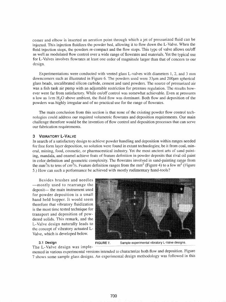
Sand Another form of ancient graphicart offers insights into powder deposition. Althoughthe history of sand-painting is far less well documented than that of enamel works, it appears tohave developed independently in different parts ofthe world for a at least a thousand years. Theapproach taken for this alternative art form is todeposit dry powders pointwise by using hoppers,sometimes rearranging it with small brushes. Curiously similar in their techniques and religiousnatures, sand paintings by Navajo Native Americans of New Mexico, and Mandalas done byTibetan monks are left as lose powders for the elements to partake .. With the advent of tourism,Navajo sand-painting can now be found in a moreresilient version, with glue sprayed over it to preserve the design. Figure 4 illustrates the level ofdetail and complexity achieved with Navajo sandpainting.
The size and complexity exhibited by TibetanMandalas clearly illustrates the potential of pointwise powder deposition in creating two dimensional patterns. Figure 5 shows the result of threeSeraje monks work over four weeks in creating aMandala. The automation and mechanization ofthis art form is in essence our project goal. FIGURE 4. Sample Navajo sand painting
(From the author's collection).
2.2 Powder transport and flow controlIn pursuit of our goal of automated Sand-Painting, one of the critical issues to be addressed is thatof bulk material transport to its eventual destination in the deposit. This is a new problem in thefreeform fabrication arena, which has only seen blanket deposition and compaction by counter-
698
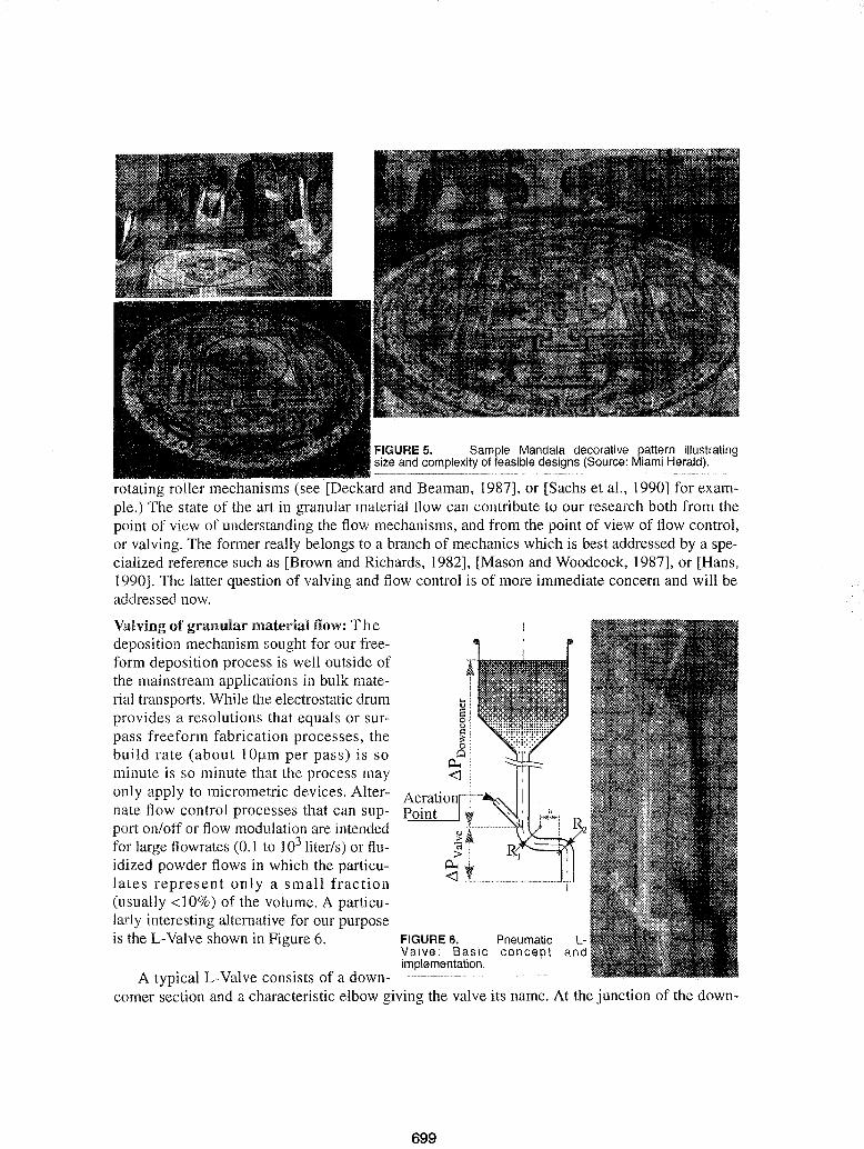
FIGURE 5. Sample Mandala decorative pattern illustratingsize and complexity of feasible designs (Source: Miami Herald).
rotating roller mechanisms (see [Deckard and Beaman, 1987], or [Sachs et aI., 1990] for example.) The state of the art in granular material flow can contribute to our research both from thepoint of view of understanding the flow mechanisms, and from the point of view of flow control,or valving. The former really belongs to a branch of mechanics which is best addressed by a specialized reference such as [Brown and Richards, 1982], [Mason and Woodcock, 1987], or [Hans,1990]. The latter question of valving and flow control is of more immediate concern and will beaddressed now.
AerationPoint
FIGURE 6. PneumaticValve: Basic conceptimplementation.
A typical L-Valve consists of a down-------------------·--·----comer section and a characteristic elbow giving the valve its name. At the junction of the down-
Valving of granular material flow: Thedeposition mechanism sought for our freeform deposition process is well outside ofthe mainstream applications in bulk material transports. While the electrostatic drumprovides a resolutions that equals or surpass freeform fabrication processes, thebuild rate (about IOflm per pass) is sominute is so minute that the process mayonly apply to micrometric devices. Alternate flow control processes that can support on/otf or flow modulation are intendedfor large flowrates (0.1 to 103 liter/s) or fluidized powder flows in which the particulates represent only a small fraction(usually <10%) of the volume. A particularly interesting alternative for our purposeis the L-Valve shown in Figure 6.
699
comer and elbow is inserted an aeration point through which a jet of pressurized fluid can beinjected. This injection fluidizes the powder bed, allowing it to flow down the L-Valve. When thefluid injection stops, the powders re-compact and the flow stops. This type of valve allows on/offas well as modulated flow control over a wide range of flowrates and typical usefor L-Valves involves flowrates at least one order of magnitude than that of concern to ourdesign.
Experimentations were conducted with vented glass L-valves with diameters 1, 2, and 3 mmdowncomers such as illustrated in Figure 6. The powders used were 33/lm and 200/lm sphericalglass beads, uncalibrated silicon carbide, cement and sand powders. The source of pressurized airwas a fish tank air pump with an adjustable restriction for pressure The results however were far from satisfactory. While on/off control was somewhat achievable. Even at pressuresa low as 1em H20 above ambient, the fluid flow was dominant. Both flow and deposition of thepowders was highly irregular and of no practical use for the range of flowrates.
The main conclusion from this section is that none of the existing powder flow control technologies could address our required volumetric flowrates and deposition requirements. Our mainchalIenge therefore would be the invention of flow control and deposition processes that can serveour fabrication requirements.
3In search of a satisfactory design to achieve powder handling and deposition within ranges neededfor free form layer deposition, no solution were found in extanttechnologies; be it from coal, mineral, mining, food, cosmetic, or pharmaceutical industry. Yet the most ancient arts of sand painting, mandala, and enamel achieve feats of feature definition in powder deposits that rival oilin color definition and geometric complexity. The flowrates involved in sand-painting fromthe mm3/s to tens of cm3/s. Feature definition ranges from the mm2 4) to a few5.) How can such a performance be achieved with mostly rudimentary hand-tools?
Besides brushes and needles-mostly used to rearrange thedeposit- the main instrument usedfor powder deposition is a smallhand held hopper. It would seemtherefore that vibratory fluidizationis the most time tested technique fortransport and deposition of powdered solids. This remark, and theL-Valve design naturally leads tothe concept of vibratory actuated LValve, which is developed below.
Sample experimental vibratory L-Valve designs.3.1 FIGURE 7.The L- Valve was ----------------------------------------------------------------
mented in various experimental versions intended to cnclractenZ;e both flow and deposition.7 shows some sample glass designs. An methodology was followed in this
Shaker
Shaker PowerSupply and
Controller
Data Acquisition
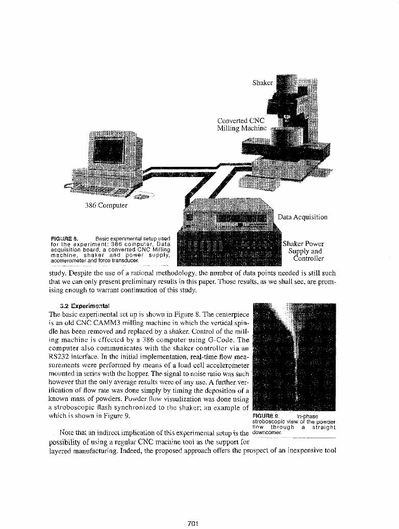
FIGURE 8. Basic experimental setup usedfor the experiment: 386 computer, Dataacquisition board, a converted CNC Millingmachine, shaker and power supply,accelerometer and force transducer.
386 Computer
study. Despite the use of a rational methodology, the number of data points needed is still suchthat we can only present preliminary results in this paper. Those results, as we shall see, are promising enough to warrant continuation of this study.
3.2 ExperimentalThe basic experimental set up is shown in Figure 8. The centerpieceis an old CNC CAMM3 milling machine in which the vertical spindle has been removed and replaced by a shaker. Control of the milling machine is effected by a 386 computer using G-Code. Thecomputer also communicates with the shaker controller via anRS232 interface. In the initial implementation, real-time flow measurements were performed by means of a load cellacceh.~rQineter
mounted in series with the hopper. The signal to noise ratio was suchhowever that the only average results were of any use. A further verification of flow rate was done simply by timing the deposition ofknown mass of powders. Powder flow visualization was done usinga stroboscopic flash synchronized to the shaker; an example ofwhich is shown in Figure 9. FIGURE 9. In-phase
stroboscopic view of the powderflow through a straight
Note that an indirect implication of this experimental setup is the ~owncomer.
possibility of using a regular CNC machine tool as the support forlayered manufacturing. Indeed, the proposed approach offers the prospect of an inexpensive tool
701
kit alternative to dedicated rapid prototyping machines, assuming of course that the shop isalready equipped with an available CNC vertical milling machine or lathe.
4 EXPERIMENTAL FLOW CHARACTERIZATION
When used in conjunction with powders, vibrations are mostly intended for compaction of a bed.In our instance, vibrations are called upon for fluidization. Preliminary experiments had shownthat at certain combinations of powders and hopper mass, vibrations could be used as a mean ofmodulation or on/off control.
Table I below outlines the key parameters which determine the outcome of the powder flowthrough the downcomer, and which must be controlled.
TABLE 1. Process parameters affecting powder flow through the downcomer.
HOPPER
We begin by conducting a series of experiments, designed to expose the relationship betweenthe flow rate and the process parameters. This experimentation is necessary as little data exists inthe literature which can be used to formulate a complete deposition model. In future developments, a theoretical study of powder flow must be carried out to compare with our experimentalresults. The ultimate goal, of course, is that the analytical model be simplified and perfectedthrough this comparison, so that, wherever possible, real-time numerical prediction of processparameters can be achieved. However, as all imaginable design cases cannot be predicted analytically, it is not realistic to obtain a complete model solely from theory. In the short term however,our goal is to obtain a set of design rules (in tabular/look-up form) to allow rapid computer controlof the process. We seek to employ empirical solutions where results cannot be obtained analyti-
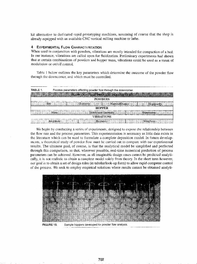
FIGURE 10. Sample hoppers developed for powder flow analysis.
702
cally. As dedicated sensing becomes available -e.g. real-time mass flow measurements- themodel will be refined and adaptive control of the process can be
>'V\a,..,h"",,,,,.., of material flowof the diameter the
Various types ofpowders were subjected to the experiment:e 022!J.m and 0250
/lm sphericalbeads.
Uncalibrated Silicon Carbidepowders.
e Uncalibratedsand.
e Uncalibratedcement powder.
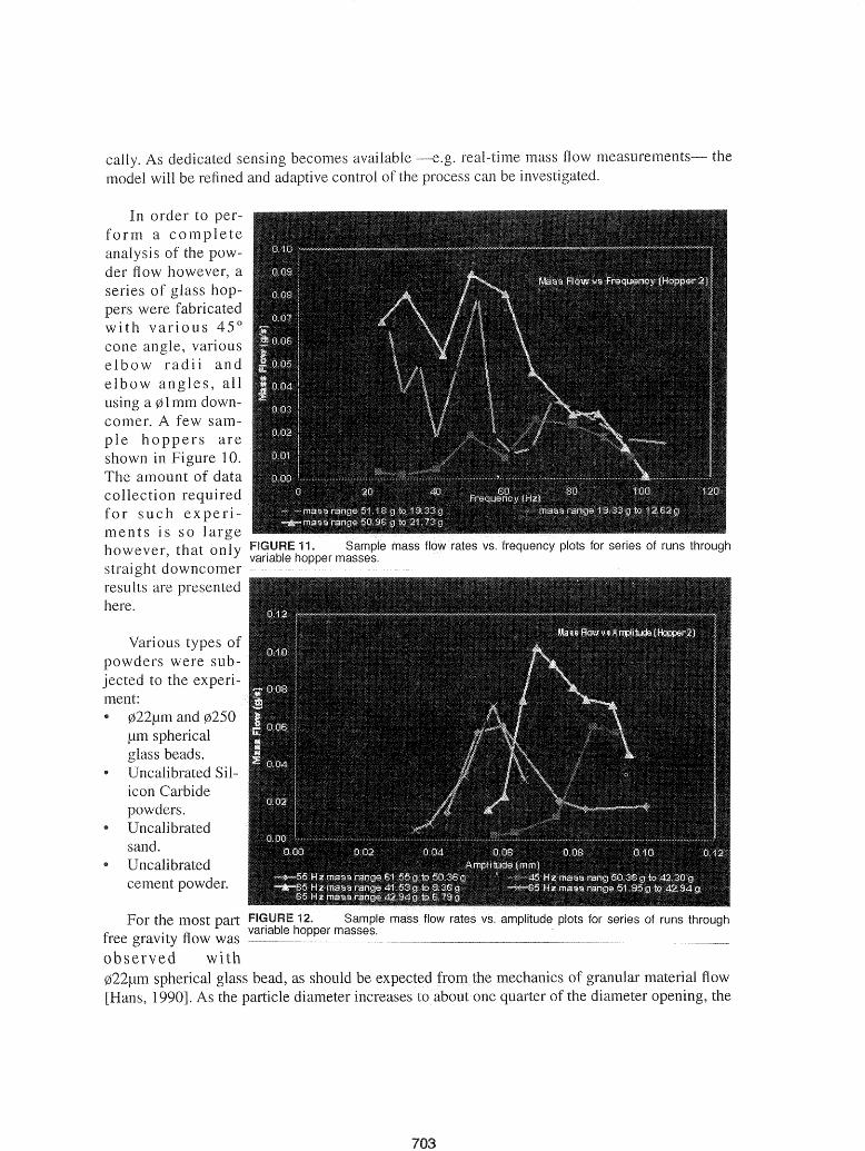
In order to perform a completeanalysis of the powder ft ow however, aseries of glass hoppers were fabricatedwith various 45°cone angle, variouselbow radii andelbow angles, allusing a 01 mm downcomer. A few sample hoppers areshown in 10.The amount of datacollection requiredfor such experiments is so largehowever, that only FIGiURiE
straight downcomerresults are presentedhere.
For the most partfree gravity flow wasobserved wi022/lm spherical glass bead, as should be av"",a,..,f".:>rl
[Hans, 1990]. As the particle diameter increases to
703
mechanics enters a rtrH-v>""'n
best flow control were "' ....""" ....10r!
... v ........., .. that the
One of thetasks
" ..... ,a .."h..,,.,. the OV .... ,;:. ..l ..
ment descherein is the
mass flowratemeasurement.cal mass fl ows are ofthe order of hundreds to tenthgram per secowhile typical h"........o ..
masses vary from 50to 150 grams.
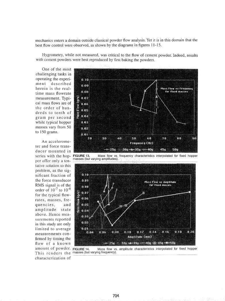
An accelerometer and force transducer mounted inseries with theper offer only a ten- .---.~----~.--.---.---..~-----:-c~~~"", ~---~,---c~.---_-_._,._-- ------.---.------- ..'--.....tative solution to this
as thenificantthe force rranSlJw:;erRMS is of theorder of 10-7 to 10-6
for the typical flowrates, masses, fre-
encies andamplitude stateabove. Hence measurementsin this study are onlylimited to averagemeasurements con-
by theflow of a knownamoun t of FIGURE 14. Mass flow vs. amplitude t"h';;lr,;;,('·torilctif'C intorrv"\I!llh:lrl
Thi s renders the masses (but varying frequency).
of
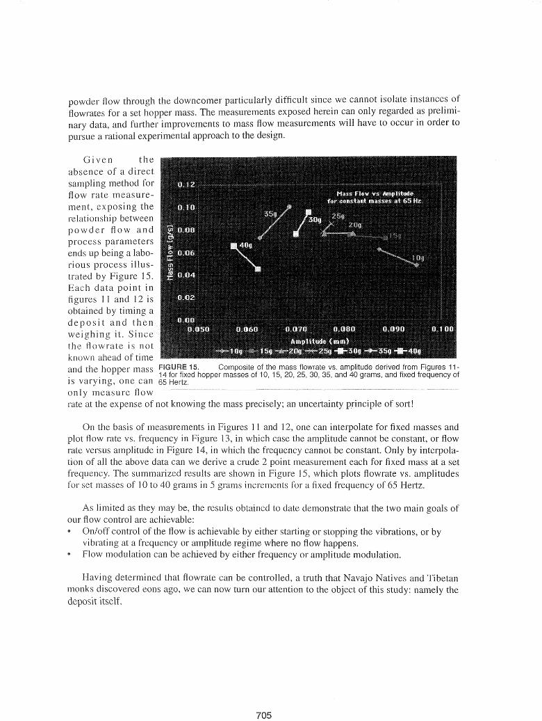
powder flow through the downcomer particularly difficult since we cannot isolate instances offlowrates for a set mass. The measurements exposed herein can only regarded as preliminary data, and further improvements to mass flow measurements will have to occur in order to
a rational approach to the design.
an uncertainty principle of sort!the mass "'1'a01001
... ,u,un,c 15. Composite of the mass flowrate VS. amplitude derived from Figures 1114 for fixed hopper masses of 10, 15, 20,25, 30, 35, and 40 grams, and fixed frequency of
is one can 65 Hertz.
only measure flowrate at the expense of not
Gi ven theabsence of a directsampling method forflow rate measurement, therelationship betweenpowder flow andprocessends up a laborious process iIIustrated by 1S.Each data point in
11 and 12 isobtained by
osit and thwei it. Sincethe flowrate is notknown ahead of timeand the mass
On the basis of measurements in 11 and 12, one can interpolate for fixed masses andplot flow rate vs. frequency in Figure 3, in which case the amplitude cannot be constant, or flowrate versus amplitude in 14, in which the cannot be constant. Only by interpola-tion of all the above data can we derive a crude 2 measurement each for fixed mass at a setfrequency. The summarized results are shown in 1 which plots flowrate vs. amplitudesfor set masses of 10 to 40 grams in S grams increments for a fixed frequency of 6S Hertz.
As limited as they may the results obtained to demonstrate that the two main goals ofour flow control are achievable:III On/off control of the flow is achievable or stopping the vibrations, or by
vibrating at a frequency or amplitude where no flow happens.Flow modulation can be achieved by either frequency or amplitude modulation.
determined that flowrate can be controlled, a that Navajo Natives and Tibetanmonks discovered eons ago, we can now turn our attention to the object of this study: namely thedeposit itself.
705
5 EXPERIMENTAL DEPOSITION CHARACTERIZATIONBefore one even embarks on a characterization of the deposit, one must develop an understandingof the powder's transition from the downcomer to the substrate. Such an understanding also leadsto a correct identification of relevant process parameters.
Experimental powder flow visualization is notoriously difficult. Given the periodic nature of the excitation though, it waslegitimate to observe the flow and flight characteristics under astroboscope. Such observation already provides a valuable insightinto the deposition process. In Figure 9 for example,' one canobserve the flow through a straight downcomer using a stroboscope in phase with the vibrations of the hopper. The flow can beobserved primarily as a series of "powder droplets" beingstretched by gravity. While the flow is observed to disperse as itfalls, it remains well focused and almost as narrow as the nozzleopening within a centimeter of the orifice.
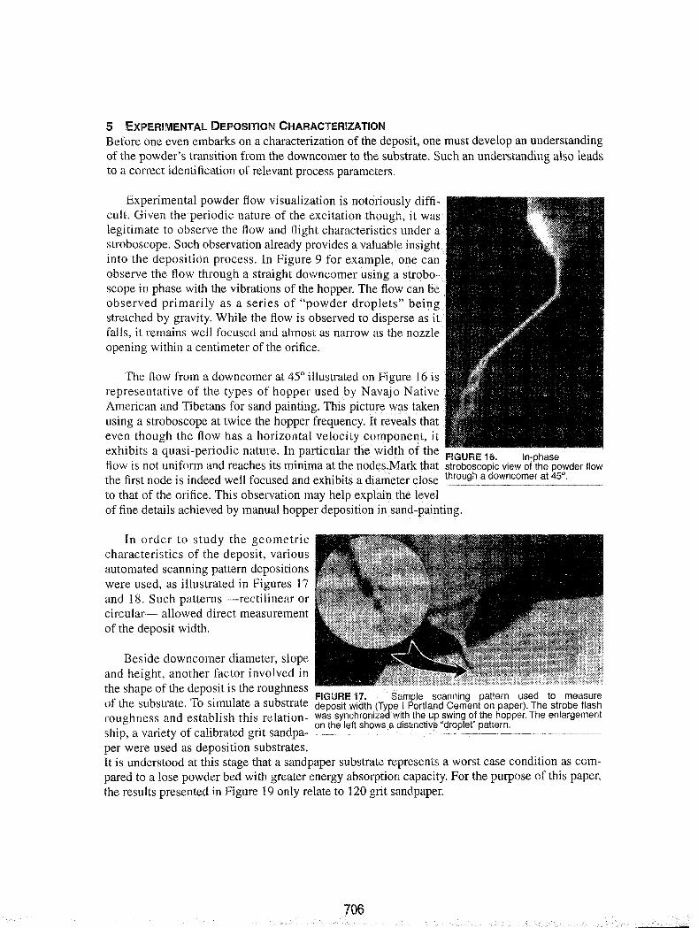
The flow from a downcomer at 45° illustrated on Figure 16 isrepresentative of the types of hopper used by Navajo NativeAmerican and Tibetans for sand painting. This picture was takenusing a stroboscope at twice the hopper frequency. It reveals thateven though the flow has a horizontal velocity component, itexhibits a quasi-periodic nature. In particular the width of the FIGURE 16. I _ h efl · 'f d h' .. h h n p asow IS not um orm an reac es ItS mInIma at t e nodes.Mark t at stroboscopic view of the powder flowthe first node is indeed well focused and exhibits a diameter close through a downcomer at 45°.
to that of the orifice. This observation may help explain the levelof fine details achieved by manual hopper deposition in. sand-painting.
In order to study the geometriccharacteristics of the deposit, variousautomated scanning pattern depositionswere used, as illustrated in Figures 17and 18. Such patterns -rectilinear orcircular- allowed direct measurementof the deposit width.
Beside downcomer diameter, slopeand height, another factor involved inthe shape of the deposit is the roughness
. FIGURE 17. Sample scanning pattern used to measureof the substrate. To SImulate a substrate deposit width :(Type,l Pqrtiand .cement on paper). The strobe flashroughness and establish this relation- was synchroOlzedwl~h the.up swmg of the hopper. The enlargement
. . on the left shows a dlstlnctlv(:l "droplet" pattern.ship, a variety of calibrated gnt sandpa--------.-.--,-------'--~-.-.--.----·-····--------_._-per were used as deposition substrates.It is understood at this stage that a sandpaper substrate represents a worst case condition as compared to a lose powder bed with greater energy absorption capacity. For the purpose of this paper,the results presented in Figure 19 only relate to 120 grit sandpaper.
706
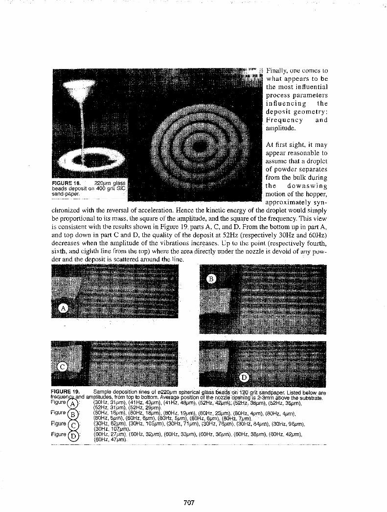
Finally, one comes towhat appears to bethe most influentialprocess parametersinfluencing thedeposit geometry:Frequency andamplitude.
FIGURE 18. 220Jlm glassbeads deposit on 400 grit SiCsand-paper.
At first sight, it mayappear reasonable toassume that a dropletof powder separatesfrom the bulk duringthe downswingmotion of the hopper,approximately syn
chronized with the reversal of acceleration. Hence the kinetic energy of the droplet would simplybe proportional to its mass, the square of the amplitude, and the squary of the frequency. This viewis consistent with the results shown in Figure 19, parts A, C, and D. From the bottom up in part A,and top down in part C and D, the quality of the deposit at 52Hz (respectively 30Hz and 60Hz)decreases when the amplitude of the vibrations increases. Up to the point (respectively fourth,sixth, and eighth line from the top) where the area directly under the nozzle is devoid of ;loY powder and the dvposit is scattered around the line.
FIGURE 19. Sample deposition lines of 0220Jlm sphericalglassbElCl.~~on> 120 grit sandpaper. Listed below arefrequen and amplitudes, from top to bottom. Average position of the nozzle opening is 2-3mm above the substrate.Figure A: (30Hz, 31/lm), (41Hz, 43Jlm), (41Hz. 48Jlm), (52Hz, 42Jlm},(52Hz,38Jlm),(52Hz, 35/lm),
(52Hz, 31/lm), (52Hz, 29Jlm).Figure (80Hz, 18Jlm), (80Hz, 18/lm), (80Hz, 19J1m), (80Hz, 2S/lm}, (80Hz, 4Jlm), (80Hz, 4Jlm),
(80Hz, 5/lm), (80Hz, 6Jlm), (80Hz, 5/lm), (80Hz, 6/lm), (80Hz, 7/lm).Figure (30Hz, 62Jlm), (30Hz, 105Jlm) , (30Hz, 71j.Jm), (30Hz, 76iJm), (30Hz, 84Jlm), (30Hz, 96pm) ,
(30Hz, 107Jlm).Figure (60Hz, 27/lm), (60Hz, 32Jlm), (60Hz, 33/lm), (60Hz, 36Jlm) , (60Hz, 38Jlm), (60Hz, 42/lm),
(60Hz, 47Jlm}.
707
Part B of Figure 19 however, appear to contradict this simple view of the deposition mechanics. Indeed at 80Hz, the quality of the deposit deteriorates rapidly between 4 and 7/lm amplitude,to be restored between 18 and 23/lm. At this time, we do not have any analytic interpretation forthe cause of this singular behavior.
Despite the lack of an analytical model of the deposition process, the experiments describedherein did identify the process parameters influencing the deposit geometry. They are listed belowin Table 2.
TABLE 2. Process parameters affecting the deposit geometry.
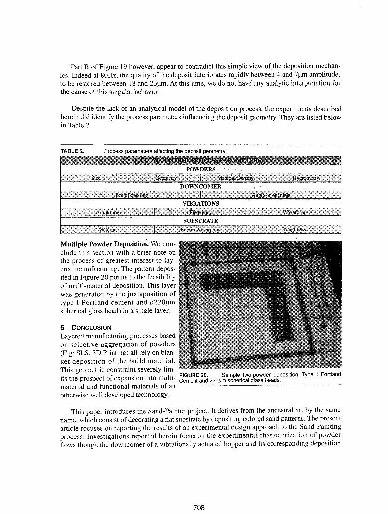
Multiple Powder Deposition. We conclude this section with a brief note onthe process of greatest interest to layered manufacturing. The pattern deposited in Figure 20 points to the feasibilityof multi-material deposition. This layerwas generated by the juxtaposition oftype I Portland cement and jij220/lmspherical glass beads in a single layer.
6 CONCLUSION
Layered manufacturing processes basedon selective aggregation of powders(E.g: SLS, 3D Ptinting) all rely on blanket deposition of the build material.This geometric constraint severely lim-its the prospect of expansion into multi- FIGURE 20. Sample two-powder deposition: Type I Portland
Cement and spherical glass beads.material and functional materials of an ~--..--C_----------------"---
otherwise well developed technology.
This paper introduces the Sand-Painter project. It derives from the ancestral art by the samename, which consist of decorating a flat substrate by depositing colored sand patterns. The presentarticle focuses on reporting the results of an experimental design approach to the Sand-Paintingprocess. Investigations reported herein focus on the experimental characterization of powderflows though the downcomer of a vibrationally actuated hopper and its corresponding deposition
708
characteristics. The results to date validate the Sand-Painter concept. The results to date though,are insufficient for an analytical characterization of the process. Yet, they establish a methodologyand approach, which can open selective aggregation processes to the realm of multi-materialstructures.
7 ACKNOWLEDGMENTS
The project presented in this paper is above all an exercise in shoestring research and scavenging.It owes much to the cooperation of the Mechanical Engineering Department at Concordia University, the Concordia Center for Advanced Vehicle Engineering (CONCAVE), and above all it owesa debt of gratitude to the undergraduate students involved. The Mechanical Engineering Department provided the computer, data acquisition, and CNC. CONCAVE provided the shaker. Theundergraduate research assistant acknowledged as co-authors provided their resourcefulness,energy and commitment.
Partial funding for this project was provided by the Natural Science and Engineering ResearchCouncil (NSERC) of Canada, and by the Concordia University Faculty Research and Development Program. All contributors are gratefully acknowledged.
8 REFERENCES
[Pegna, 1995a] "Application of Cementitious Bulk Materials to Site Processed Solid FreeformConstruction," Proceedings of the Solid Freeform Fabrication Symposium, Ed. by H.L Marcus,J.1. Beaman, D.L. Bourell, Joel W. Barlow, and R. H. Crawford, Austin, Tx, August 1995, pp.3945.[Pegna,1995b] "Exploratory Investigation Of Layered Fabrication Applied To ConstructionAutomation," Proceedings of the ASME Design Technical Conferences, Design Automation Conference, Sept. 17-21,1995, Boston, Ma., DE-Vol. 82, pp.219-226.[Pegna,1997] "Exploratory Investigation of Solid Freeform Construction," Automation in Con~~~, Vol. 5, no.5, pp. 427-437 (Mar. 97)[Rock and Gilman, 1995] "A New SFF Process for Functional Part Rapid Prototyping and Manufacturing: Freeform Powder Molding", Proceedings of the Solid Freeform Fabrication Symposium, Ed. by H.L Marcus, J.1. Beaman, D.L. Bourell, Joel W. Barlow, and R. H. Crawford, Austin,Tx, August 1995, pp.80-87.[Sachs et 1990] Sachs, E., Cima, M., Cornie, J.; "Three Dimensional Printing: Rapid Tool-ing and Prototypes Directlyfor a CAD Model," Annals of CIRP, Vo1.39, 1, pp. 201-204 (1990)[Deckard and Beaman, 1987] "Solid Freeform Fabrication and Selective Laser Sintering" Proceedings of the 15th NAMRC-SME, (1987)[Brown and Richards, 1982] Principles of Powder Mechanics, Pergamon Press, 2nd ed. (1987)[Mason and Woodcock, 1987] Bulk Solids Handling, Leonard Hill, N. Y, 1987[Hans, 1990] Particle Technology, Chapman And Hall, N.Y 1990[Taguchi, 1987] System of Experimental Design I & II, UNIPUB Kraus International Publications (1987).
709

710