Embed Size (px)
Citation preview
The Sagnac Effect and Uniform Motion A. G. Kelly, HDS Energy, Kells Co. Meath, Ireland. [email protected].
Abstract
The Sagnac effect shows that light signals emitted upon a rotating disc do not travel at the same speed with and
against the direction of rotation of the disc. It has been long debated whether this same effect applies in the case
were light signals are emitted upon a body in uniform translational motion. This paper shows that the Sagnac
effect also applies in the latter case
A general derivation of the Sagnac formula is given for any shape of light path.
The Sagnac Effect.
The Sagnac effect [1] was discovered by a Frenchman of that name, and published in 1913, which was three
years before the General Theory of Relativity was introduced by Einstein.
Sagnac showed that light took different times to traverse a path, in opposite directions, upon a spinning
disc.
A
B
D
C
E
F
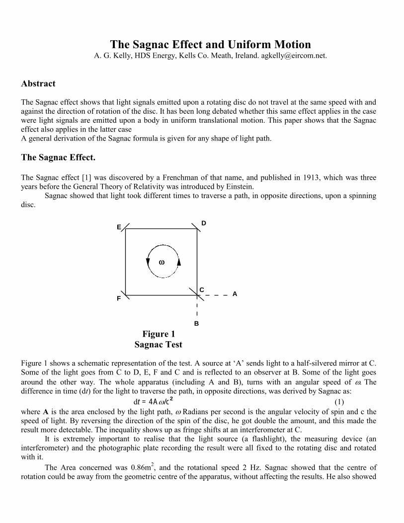
Figure 1
Sagnac Test
Figure 1 shows a schematic representation of the test. A source at ‘A’ sends light to a half-silvered mirror at C.
Some of the light goes from C to D, E, F and C and is reflected to an observer at B. Some of the light goes
around the other way. The whole apparatus (including A and B), turns with an angular speed of The
difference in time (dt) for the light to traverse the path, in opposite directions, was derived by Sagnac as:
dt = 4A/c2 (1)
where A is the area enclosed by the light path, Radians per second is the angular velocity of spin and c the
speed of light. By reversing the direction of the spin of the disc, he got double the amount, and this made the
result more detectable. The inequality shows up as fringe shifts at an interferometer at C.
It is extremely important to realise that the light source (a flashlight), the measuring device (an
interferometer) and the photographic plate recording the result were all fixed to the rotating disc and rotated
with it.
The Area concerned was 0.86m2, and the rotational speed 2 Hz. Sagnac showed that the centre of
rotation could be away from the geometric centre of the apparatus, without affecting the results. He also showed
that the shape of the circuit was immaterial; a proof of this will later be derived.
Sagnac thought the so-called ‘ether’ was the cause of the difference but, as will be later shown, there is
another explanation.It seems that the work of Sagnac and of others, who later did the same test, was ignored
because they thought it was caused by an ‘ether’, which was later said by Einstein to be superfluous. Sagnac
published a dozen articles from 1897 to 1914, on the behaviour of light and interferometry. He devised many
novel items of equipment, to solve the problems he posed.
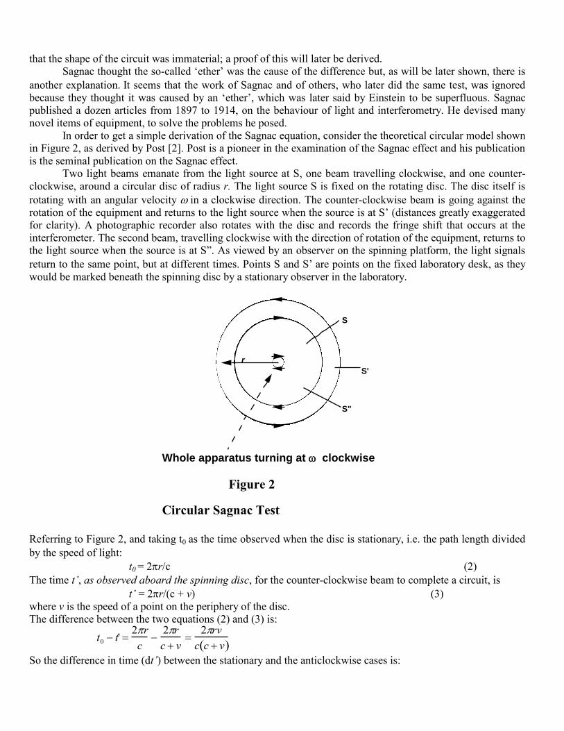
In order to get a simple derivation of the Sagnac equation, consider the theoretical circular model shown
in Figure 2, as derived by Post [2]. Post is a pioneer in the examination of the Sagnac effect and his publication
is the seminal publication on the Sagnac effect.
Two light beams emanate from the light source at S, one beam travelling clockwise, and one counter-
clockwise, around a circular disc of radius r. The light source S is fixed on the rotating disc. The disc itself is
rotating with an angular velocity in a clockwise direction. The counter-clockwise beam is going against the
rotation of the equipment and returns to the light source when the source is at S’ (distances greatly exaggerated
for clarity). A photographic recorder also rotates with the disc and records the fringe shift that occurs at the
interferometer. The second beam, travelling clockwise with the direction of rotation of the equipment, returns to
the light source when the source is at S”. As viewed by an observer on the spinning platform, the light signals
return to the same point, but at different times. Points S and S’are points on the fixed laboratory desk, as they
would be marked beneath the spinning disc by a stationary observer in the laboratory.
r
S
S'
S"
Whole apparatus turning at clockwise
Figure 2
Circular Sagnac Test
Referring to Figure 2, and taking t0 as the time observed when the disc is stationary, i.e. the path length divided
by the speed of light:
t0 = 2r/c (2)
The time t‟, as observed aboard the spinning disc, for the counter-clockwise beam to complete a circuit, is
t‟ = 2r/(c + v) (3)
where v is the speed of a point on the periphery of the disc.
The difference between the two equations (2) and (3) is:
t0 t' 2r
c2r
c v2rv
c c v So the difference in time (dt‟) between the stationary and the anticlockwise cases is:
dt‟ = (t0 – t‟) = t0v/(c + v) (4)
For the other direction, where t” is the time for the clockwise beam to arrive back at point S”, the difference
(dt”) between the stationary and the clockwise case is similarly:
dt” = (t” – t0) = t0v/(c – v) (5)
Equations (3) and (5) may be stated as follows: the moving observer thinks that the light has, relative to oneself,
completed one revolution of the disc (2r) at velocities of c ± v in the two opposing directions.
To get the difference in time (dt) between the time for the light to go clockwise, and the time to go
counter-clockwise, adding equation (4) from (5) gives dt‟ + dt” = dt, and where v = r for circular motion and
A = r2 is the enclosed area.
dt = 4A(c2 – v
2) (6)
and, because v2 is negligible for practical tests, this term can be ignored, giving the formula developed by
Sagnac. Other relationships exist. The time differences for the light signals to come back to the place where the
light was emitted are also expressible as follows:
dt‟ = t‟v/c, and dt” = t”v/c (7)
Taking the distance SS’ as ds’ and SS” as ds”, then, because ds‟/v = t‟, and ds”/v = t”, from Equations (3) and
(4):
dt‟ = ds‟/c and dt” = ds”/c (8)
From (4) and (5) t” – t‟ = dt” + dt’ = [ds’ + ds”]/c. Note that it is the addition of (not the difference
between) the two increments of movement ds’ and ds”, divided by the speed of light, that gives the difference in
the times taken by the two opposing beams of light that traverse the circuit.
The calculation above is done on the presumption that there is a difference in the time for the signals to
get back to the starting point, as is found in practice. The above derivation is used to put a value on the
difference. Had no difference been discovered by Sagnac, then no derivation would be attempted!
Another method of deriving the same formula is to assume that the light travels with respect to the
laboratory. If this assumption gives the precise Sagnac result, then this proves that, indeed, the light behaves in
this way. As before, t0 is the path length (2r) divided by the speed of light: t
0 = 2r/c.
When the disc is put in motion, a light signal is emitted from the light source at S; a portion of the signal
goes clockwise (denoted by the inner line in Figure 2), and some goes anticlockwise. Both signals are here
assumed to independent of the speed of the source at S, and are also assumed to travel relative to the laboratory.
Let t’ be the time for the light to go from S to S’ in the anticlockwise direction.
t‟ = [2r – ds‟]/c (9)
But, t‟ is also the time taken for the disc periphery to move the distance ds' in the clockwise direction at speed v.
Therefore t‟ = ds‟/v, and ds‟ = t‟v and,
ds‟ = [2r – ds‟]v/c
ds‟/v = 2r/[c + v]
t’ = 2r/[c + v] (10)
Similar calculations for t” give the time for the light to go from S to S” in a clockwise direction,
t” = 2r/[c – v] (11)
Subtracting these two equations, the difference (dt) between the times for the light to go clockwise (t”) and
anticlockwise (t‟) is
dt 2 r
c v 2 r
c v 4 rv
c 2 v
2 (12)
This is the same as already derived above by the first method, in equation (6).
Equations (9) and (10) are mathematically equivalent; they both give the same time interval. Equation
(9) may be stated as follows; the observer in the fixed laboratory observes that the disc periphery moves a
distance ds‟ while the light completes a distance of 2r – ds‟ around in the other direction from S to S’. The
equation describes the time interval, as it would be discerned by the observer in the laboratory. Remember that
the actual ‘observer’ (the interferometer) in Sagnac’s tests was riding upon the spinning disc.
The Sagnac effect shows that the light is not affected by the movement of the source of that light. It also
shows that the light travels relative to the laboratory, because assuming that the light travels relative to the
laboratory gives the correct result in all cases. The assumption that the speed of light is independent of the
speed of its source (as is sound) is one of the assumptions made by Einstein on the behaviour of light.
To get a fringe shift of one fringe, the velocity of Point S in Figure 2, relative to the laboratory, has to be
about 13 m/s per meter of radius. This is a very low velocity, where relativity theory cannot possibly have any
function.
Fringe shift is got from time difference by multiplying by c/. Wherethe wavelength of light5500 x
10-10
m, and v = r, this gives v = 13.13m/s, per meter of radius, from:
14A
c
4rv
3x108x5,500x10
10
(13)
In equation (4), for small values of v, dt’ is t0v/c. As v approaches c, dt‟ becomes t0/2, and the speed
relative to the observer is now becomes 2c. In equation (5), as the speed v approaches c, dt” becomes infinite,
because the light and the Point S, are travelling in the same direction and the time for the light signal to gain
one complete circuit on the Point S is infinite. At very low velocities, the result is again t0v/c.
Dufour & Prunier Tests
The French pair, Dufour & Prunier (D & P) [3] repeated the Sagnac test, forty years after Sagnac had done it,
and got the same result. They then did other very important variations on the original Sagnac experiments. They
showed that the photographic record could be taken upon the spinning disc or from the fixed laboratory and that
the result was the same.
This author has located no reference by Einstein to the Sagnac tests, and that can be viewed as very
strange because the tests were on the speed of light, which is the basis and core of Special Relativity. Einstein
visited Miller [4] in the USA in 1921 where tests on the speed of light were in progress. Lorentz also visited the
same site. Sagnac’s work was referenced by Silberstein [5] (1921) who worked with Michelson & Gale [6] on
their on 1925 tests (described below). Miller was a co-worker with Michelson. Silberstein remarked “As a
matter of fact, Einstein himself never entered into the details of this important problem of rotation” and “In
fine, the optical circuit experiment may easily become crucial and fatal for Einstein‟s theory.” Turner [7]
(1979) commented that neither the Sagnac tests nor the Michelson & Gale tests were ever mentioned by
Einstein.
Michelson & Gale Test
In 1904, Michelson [8] proposed a test to prove whether or not there was an ‘ether’. This test is of direct
interest in the present debate, not because of a debate on a possible ether, but because the tests he proposed, and
subsequently carried out, are pertinent to the behaviour of light. He proposed that if two pencils of light were to
be sent around the earth in opposite directions, and parallel to the equator, then any difference in their time to
traverse the circumference would be discernible. He then had the idea, that a short portion of the circumference
traversed in either direction would give a measure of the same phenomenon. He said “but it is not necessary
that the path should encircle the globe, for there would still be a difference in time for any position of the
circuit.” By taking a short part of the circumference, he proposed that by measuring the proportion of this part
to the whole circumference, he could compute the effect for the whole circumference.
He calculated that for a circuit of one kilometer square, the effect should show a measurable fringe shift.
In such a test in 1925 (Figure 3), when Michelson was 73 years of age, Michelson and Gale (M & G hereafter)
constructed a large rectangular pipe system laid on the ground (it was 2010 feet from East to West and 1113
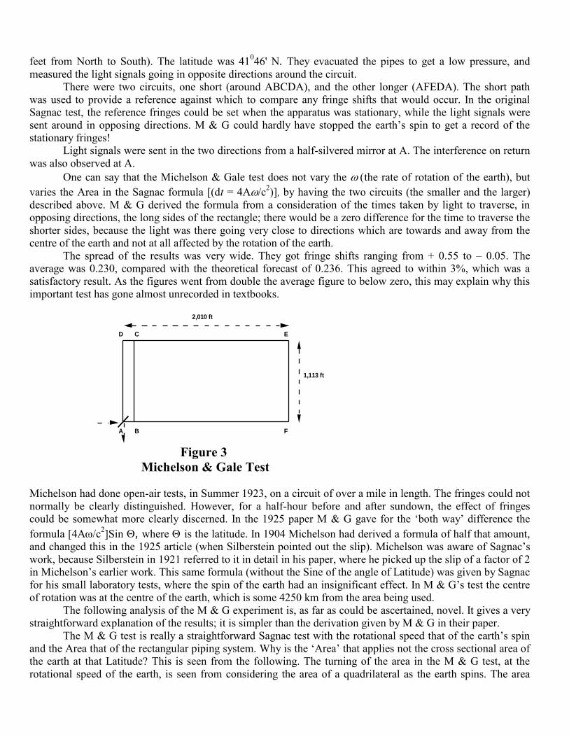
feet from North to South). The latitude was 41046' N. They evacuated the pipes to get a low pressure, and
measured the light signals going in opposite directions around the circuit.
There were two circuits, one short (around ABCDA), and the other longer (AFEDA). The short path
was used to provide a reference against which to compare any fringe shifts that would occur. In the original
Sagnac test, the reference fringes could be set when the apparatus was stationary, while the light signals were
sent around in opposing directions. M & G could hardly have stopped the earth’s spin to get a record of the
stationary fringes!
Light signals were sent in the two directions from a half-silvered mirror at A. The interference on return
was also observed at A.
One can say that the Michelson & Gale test does not vary the the rate of rotation of the earth), but
varies the Area in the Sagnac formula [(dt = 4A/c2)], by having the two circuits (the smaller and the larger)
described above. M & G derived the formula from a consideration of the times taken by light to traverse, in
opposing directions, the long sides of the rectangle; there would be a zero difference for the time to traverse the
shorter sides, because the light was there going very close to directions which are towards and away from the
centre of the earth and not at all affected by the rotation of the earth.
The spread of the results was very wide. They got fringe shifts ranging from + 0.55 to – 0.05. The
average was 0.230, compared with the theoretical forecast of 0.236. This agreed to within 3%, which was a
satisfactory result. As the figures went from double the average figure to below zero, this may explain why this
important test has gone almost unrecorded in textbooks.
B F
E C D
A
2,010 ft
1,113 ft
Figure 3
Michelson & Gale Test
Michelson had done open-air tests, in Summer 1923, on a circuit of over a mile in length. The fringes could not
normally be clearly distinguished. However, for a half-hour before and after sundown, the effect of fringes
could be somewhat more clearly discerned. In the 1925 paper M & G gave for the ‘both way’ difference the
formula [4Ac2]Sin , where is the latitude. In 1904 Michelson had derived a formula of half that amount,
and changed this in the 1925 article (when Silberstein pointed out the slip). Michelson was aware of Sagnac’s
work, because Silberstein in 1921 referred to it in detail in his paper, where he picked up the slip of a factor of 2
in Michelson’s earlier work. This same formula (without the Sine of the angle of Latitude) was given by Sagnac
for his small laboratory tests, where the spin of the earth had an insignificant effect. In M & G’s test the centre
of rotation was at the centre of the earth, which is some 4250 km from the area being used.
The following analysis of the M & G experiment is, as far as could be ascertained, novel. It gives a very
straightforward explanation of the results; it is simpler than the derivation given by M & G in their paper.
The M & G test is really a straightforward Sagnac test with the rotational speed that of the earth’s spin
and the Area that of the rectangular piping system. Why is the ‘Area’ that applies not the cross sectional area of
the earth at that Latitude? This is seen from the following. The turning of the area in the M & G test, at the
rotational speed of the earth, is seen from considering the area of a quadrilateral as the earth spins. The area
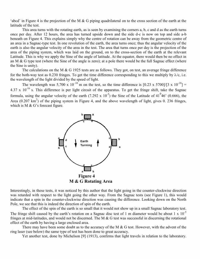
‘abcd’ in Figure 4 is the projection of the M & G piping quadrilateral on to the cross section of the earth at the
latitude of the test.
This area turns with the rotating earth, as is seen by examining the corners a, b, c and d as the earth turns
once per day. After 12 hours, the area has turned upside down and the side d-c is now on top and side a-b
beneath on Figure 4. This explains simply why the centre of rotation can be away from the geometric centre of
an area in a Sagnac-type test. In one revolution of the earth, the area turns once; thus the angular velocity of the
earth is also the angular velocity of the area in the test. The area that turns once per day is the projection of the
area of the piping system, which was laid on the ground, on to the cross-section of the earth at the relevant
Latitude. This is why we apply the Sine of the angle of latitude. At the equator, there would then be no effect in
an M & G type test (where the Sine of the angle is zero); at a pole there would be the full Sagnac effect (where
the Sine is unity).
The calculations on the M & G 1925 tests are as follows. They got, on test, an average fringe difference
for the both-way test as 0.230 fringes. To get the time difference corresponding to this we multiply by c, i.e.
the wavelength of the light divided by the speed of light.
The wavelength was 5,700 x 10–10
m on the test, so the time difference is [0.23 x 5700]/[3 x 10-18
] =
4.37 x 10⁻¹⁶
s. This difference is per light circuit of the apparatus. To get the fringe shift, take the Sagnac
formula, using the angular velocity of the earth (7.292 x 10⁻⁵
) the Sine of the Latitude of 41046’ (0.666), the
Area (0.207 km2) of the piping system in Figure 4, and the above wavelength of light, gives 0. 236 fringes,
which is M & G’s forecast figure.
ab
c d
cd
ba
Earth
Turning
b
ad
c
c
da
b
Figure 4
M & G Rotating Area
Interestingly, in these tests, it was noticed by this author that the light going in the counter-clockwise direction
was retarded with respect to the light going the other way. From the Sagnac tests (see Figure 1), this would
indicate that a spin in the counter-clockwise direction was causing the difference. Looking down on the North
Pole, we see that this is indeed the direction of spin of the earth.
The effect of the spin of the earth is so small that it would not show up in a small Sagnac laboratory test.
The fringe shift caused by the earth’s rotation on a Sagnac disc test of 1 m diameter would be about 1 x 10⁻⁵
fringes at mid-latitudes, and would not be discerned. The M & G test was successful in discerning the rotational
effect of the earth by having a large enclosed area.
There may have been some doubt as to the accuracy of the M & G test. However, with the advent of the
ring laser (see below) the same type of test has been done to great accuracy.
Yet another test, done by Michelson [9] (1913), confirms that light travels in relation to the laboratory.
In this test he bounced light beams off rotating mirrors, which were rotating at 1800 rpm. He proved from the
resulting fringe shift that:
(1) the light does not bounce off such a mirror, as would a tennis ball bounce off a moving racquet.
(2) light does not take up the movement of the mirror; that is, the velocity of the source of the reflected
beam coming off the rotating mirror does not have any change in its velocity, caused by that moving mirror.
(3) the light actually ignores the whole rotating apparatus. It moves solely with respect to the laboratory.
This test is a clear confirmation that the conclusions in this paper in respect of Sagnac-type tests are
correct. The accuracy of the Michelson test was 1:50.
Oddly, in this 1913 paper Michelson made an error of a factor of 2, but this was cancelled out later by
his omission of a similar amount; this was uncovered by a colleague who has been corresponding with this
author on that test. Michelson seemed to specialise in making errors of a factor of 2! But, his results were
experimental and stand.
Ring Laser
The development of the ring laser has led to a far more accurate method of measuring the Sagnac effect. The
accuracy in Sagnac’s time was about 1:100. In 1963 Macek and Davis [10] carried out a Sagnac test using
lasers on a rotating disc of about the same size as had been used by Sagnac. Their tests gave an accuracy of 1 in
1012
. Bilger et al. (1995) [11] carried out a test, using a ring laser that was fixed to the earth, as was the
Michelson & Gale piping system. Their aim was to determine the rotational effect of the earth on the behaviour
of laser light, which was sent in opposing directions around a small circuit in the laboratory. The circuit was a
square of area 0.75 m2 and they used a piping system filled with a Helium-Neon gas. The test was done at a
Latitude of 43029’S in New Zealand. The apparatus was 30 m underground, fixed in a cubic meter of concrete,
tied into basalt.
The ring laser has a property that gives rise to the beating of counter propagating modes, at a frequency
df given by df = [4A]/[P] where is the angular rotation of the earth, the wavelength of the light used,
and P is the perimeter of the ring laser. Bilger et al. achieved an accuracy of better than 1 part in 1020
. The
accuracy of this result is a twelve order of magnitude improvement on the M & G test, while the area concerned
is less by a factor of 277,000 (Anderson et al, 1994) [12].
The performance of the ring laser is somewhat different from that of the traditional Sagnac test. In the
ring laser there are set up standing waves of the laser light. These are like the standing waves set up by shaking
a long rope that is fixed at the far end, or like the resonant vibrations of a violin string. In a circular ring laser
these waves stay stationary in relation to the laboratory (Martin, 1996) [13]. If the ring is now rotated the nodes
of the standing waves can be recorded as they pass by an observation post. This is a different phenomenon from
the recording of a movement of fringes from their stationary position in a Sagnac test. The speed of the passing
nodes in the ring laser test depends upon the shape of the ‘ring’. In the case of, for example, a square or triangle,
the wave rotates at a different rate than in the case of a circular configuration. In all cases, the velocity of the
passing nodes is directly proportional to the rotation rate. This phenomenon is further confirmation of the
proposal in this paper, that light, in small scale experiments, travels relative to the laboratory (Anderson, 1986;
[14]).
It was noticed by this author that in the Bilger et al. test the rotation that caused the retardation of the
laser was clockwise when viewed from over the South Pole. This retardation was in the opposite sense to that in
the northern hemisphere M & G test. This Bilger et al. result therefore also conforms with the Sagnac effect.
There was a considerable element of luck in the original Sagnac experiment. It was later found that the
light signals can lock on to the circuit and mirrors unless there is considerable vibration; such vibration was
present in the Sagnac experiment. In later designs a dither is introduced to ensure that locking does not occur.
History would, no doubt, have taken a different turn had the Sagnac test results given a zero result, which
would have been the case had the equipment been rock steady; in that case it would have been taken as proof
positive of SR!
Circular Path versus Straight Line
Einstein (1905) [15] accepted that movement on a circular path had the same result as movement in a straight
line, when considering the question of measurement of distance or time. He derived the relationship between
the time being kept by a stationary clock and a moving clock. Einstein said, when referring to the moving
clock,:
it follows that the time marked by the clock (viewed in the stationary system) is slow by 1 – √(1 – v2/c
2)
seconds per second, or - neglecting magnitudes of fourth and higher order - by 1/2v2/c
2.
Having thus derived his formula for straight line movements, he said:
it is at once apparent that this result still holds good if the clock moves from A to B in any polygonal
line;….if we assume that the result proved for a polygonal line is also valid for a continuously curved line, we
arrive at this result: If one of two synchronous clocks at A is moved in a closed curve with constant velocity
until it returns to A, the journey lasting t seconds, then by the clock which has remained at rest the travelled
clock on its arrival at A will be 1/2tv2/c
2 second slow.
Even though the effect he described is infinitesimally smaller than the Sagnac effect it is the argument
of application, from a straight path to a curved path, that is of interest here.
This conclusion, that the curved path is the same as a straight path when considering motion and time,
might be queried, in relation to the centrifugal force effect for uniform circular motion. But, as Young [16] puts
it “there is no component of acceleration parallel to the path; otherwise the speed would change.”
In 1919 three years after the publication of the General Theory, Einstein repeated the statement when he
wrote “The rotating observer notes very well that of his two equivalent clocks, that placed on the circumference
runs slower than that placed at the centre.”
The path, in Sagnac’s original test, was made up of straight lines. Harress [17] (1911) did tests with a
series of ten prisms around the circumference of a disc; in this case short straight lines were also present. One of
Pogany’s tests (1928) [18] had the light travelling around the four sides of an approximate square. This also
confirms that the light emitted upon a rotating disc, when travelling in a straight line (on a polygonal section),
does not travel at the speed c relative to the moving disc. As stated by Einstein (1905), there is no reason to
credit that light, which travels in a series of polygonal lines, will behave differently from light travelling off in
one straight line. Many references try to claim that we cannot apply SR to motion in a circle, or on a closed
circuit, or to anything but straight line motion; but Einstein applied that theory to those situations in the basic
paper on SR. As we know, Einstein (1916) [19] later changed his mind when he launched his General Theory.
He wrote
The word „special‟ is meant to intimate that the principle is restricted to the case when K‟ has a motion
of uniform translation relatively to K, but that the equivalence of K‟ to K does not extend to the case of non-
uniform motion of K‟ relatively to K.
This is an example of where authors can selectively quote Einstein’s writings, whenever there is a
seemingly insurmountable difficulty with SR theory.
Sagnac Effect and Uniform Translational Motion
There is no such thing as a perfect Inertial Frame. Everything in the Universe is in motion. The earth and
everything upon it, and all other planets and stars are in some motions. The best we can do is choose a Frame
that is acceptable for the purpose of our measurements in a particular experiment.
Many authors claim that no matter how large the disc, it does not approximate to a straight line, because
there is still some rotation involved. The centre of the earth (moving around the Sun) is taken as a suitable and
perfectly acceptable inertial frame for Global Positioning System measurements; these record the time recorded
by clocks upon the surface of the earth or upon satellites. The standards for synchronising clocks upon the earth
are set down by the Consultative Committee for the Definition of the Second (CCDS) (1980) [20] and the
International Telecommunications Union (1990) [21]. These standards accept the centre of the earth as an
acceptable inertial frame for all measurements with reference to timekeeping. The well known Hafele &
Keating (1972) [22] experiment also claimed that nearby space, moving with the earth, was acceptable as a
suitable inertial frame. This is equivalent to the geocentre as far as movement is concerned.
Let us see how the ‘perfectly acceptable’ frame of the centre of the earth compares with that used in the
various experiments described earlier.
The sending of a clock around the globe on an aeroplane (as done by Hafele & Keating) takes about 40
hours flying time. During that time, the earth turns by 1.6 degrees of its orbital 360 degrees path around the
Sun.
The centre of the earth turns 2.9 x 10⁻⁶
orbital degrees around the Sun during a test involving the
sending of an electromagnetic signal around the earth at the equator (in Global Positioning System tests).
During the Michelson & Gale test, the earth turned through an orbital angle of 2.3 x 10⁻¹⁰
degrees. So,
this rotation is less by 10,000,000,000 than the frame acceptable in the H & K case!
While the light signal went around the Bilger et al. apparatus described earlier, the earth turned on its
axis by 1.66 x 10⁻¹³
degrees. Bilger et al. used a square of side 0.866m upon a disc of 8,750,000m diameter (the
cross section of the earth at that Latitude).
In the small laboratory-type tests the daily spin of the earth would cause a turn by 365 times the above
figures.
The non-rotating centre of the earth is acceptable by adherents of the theory of SR as a suitable place to
set up a satisfactory Inertial Frame of reference. But the surface of the earth (the laboratory in this case) is not
considered as an Inertial Frame for the Bilger et al. test, even though there is no relative motion between
observer and apparatus, and the centre of the earth rotates, in the H & K case, by an angle greater by
10,000,000,000,000 than occurs during the Bilger et al. test. Also, in the Bilger test there is a rotation which is
less by 5 x 10⁶
than in the Global Positioning System case.
In the original Sagnac test the earth would have turned 2.8 x 10⁻¹³
orbital degrees during the test. During
a GPS test around the globe at the equator, the earth would have turned by 10,000,000 times the amount it
turned during a Sagnac test. Pretending that SR does not apply to rotation, while at the same time applying it
daily to experiments like the Global Positioning System, that has a far greater amount of rotation than the
Sagnac experiment, is indefensible. We could be forgiven for saying that this is a very biased selection of what
is termed an 'Inertial Frame'.
The results are the same for spinning discs of any radius; with a disc of radius approaching infinity, the
result approximates to a straight line. The effect thus applies to all objects moving at constant speed. Post
(1967) saw that there was a problem with the straight line versus the rotating disc. He said:
To be consistent with the principle of relativity one has to demand that the Sagnac interferometer and
the ring laser cannot lead to a fringe shift or a beat frequency if the equipment is in uniform translational
motion. The special theory of relativity does not apply to Sagnac because Lorentz transformations are
restricted to pure translation. While this saved the situation from formal contradictions, it did leave a
disturbing conceptual discontinuity. Why did galilean kinematics suffice for rotational motion and then fail for
pure translation?
In other words, why was it that SR theory was useless for any motion other than uniform straight line
relative motion, while the old Newtonian theory could explain rotational motion, but was insufficient for the
simplest motion of all - uniform straight line motion!
Indeed, the Sagnac disc need not approach infinite radius to give us the straight-line effect. If the disc is
so large that we cannot distinguish, with the most accurate instrumentation, any deviation from a straight line,
then the result is applicable to straight-line motion. As the earth is moving in space with all sorts of movements,
from the movement of our Universe to the orbital movement around the Sun, we cannot ever have an ideal
Inertial Frame on the earth. The deviation from a straight line on a distance such as used in the M & G (600m)
or Saburi (0.9m) tests will not be distinguishable.
What have we measured by the fringe shifts recorded in the Sagnac tests? We have indirectly measured
the time taken by the two opposing beams of light to traverse the spinning disc in opposing directions. We have
thus proved that the light travels at different speeds in relation to an observer upon the spinning disc.
A recent ingenious test by Wang et al. (2003) [23] shows that the Sagnac result is also got by sending
out light in a straight line portion of the light path and back again. This is what this author claimed above, but it
is so much more convincing when an actual experiment has shown the same thing. Wang achieved the
seemingly impossible, by reversing a light beam sent out on a straight line on a moving platform and measuring
the difference in time to return.
Any claims that the Sagnac experiment upsets SR were heretofore brushed aside by a statement that
Sagnac is a rotational experiment and SR does not apply to rotational experiments. That defence is now shown
to be groundless.
Special Relativity versus Sagnac Effect
Claiming that SR explains the Sagnac effect is like saying that it explains the bouncing of a rubber ball against
the wall of a house, or the fall of a snowflake. The analysis of such experiments do not contradict SR, but the
latter has no part in any explanation of the phenomenon.
Some publications, that try to use SR to explain the Sagnac effect, apply the ‘gamma’ factor to the
denominator of the Sagnac equation (4A/c2) and later also in the numerator, thus cancelling out. They then
declare victoriously that the answer conforms with the Sagnac results.
Many authors state that SR is not relevant to rotating frames of reference, and therefore is not relevant to
the Sagnac effect, as if that explains the whole matter! Well, if that is so, what on earth (pun) is the
explanation?
It was shown in Kelly (2001) [24] that the Sagnac effect, and the effect calculated by the SR are of very
different orders of magnitude, and that SR has no role in trying to explain the Sagnac effect. Post (1967) shows
that the two are of very different orders of magnitude. He says that the dilation factor to be applied under SR is
“indistinguishable with presently available equipment” and “is still one order smaller than the Doppler
correction, which occurs when observing fringe shifts” in the Sagnac tests. He also points out that the Doppler
effect “is v/c times smaller than the effect one wants to observe." Here Post states that the effect forecast by SR,
for the time dilation aboard a moving object, is far smaller than the effect to be observed in a Sagnac test.
General Derivation of Sagnac Equation
As far as could be ascertained this is the first general derivation of the Sagnac effect which does not assume an
ether. It is derived on the assumption that the light travels with respect to the laboratory, as proven above.
Sagnac developed the mathematics of his equation based on the assumption that an ‘ether’ existed.
Fortunately, the result is the same as if the light were measured as travelling at a constant speed with respect to
the stationary laboratory, as has been shown to be the case in this paper. Because the effect of an ‘ether’ would
be to slow down the light in its travel when going with the rotation of the equipment, and to speed it up when
going the other way, this gives the same mathematics as those we need. In our case, the rotating equipment tries
to leave the light behind, when rotating in one direction, and tries to catch up with it when going in the reverse
direction. This has the same effect, as if there were in fact an ether. It is probably because of his insistence on
the ether that Sagnac’s results have not been recognised for their full pioneering worth. Researchers are too
busy to bother reading old papers on ether theory!
Let us here set down the general mathematics of the Sagnac effect, upon a quadrilateral shape as used by
Sagnac in his tests, and upon the assumption that the light is travelling in relation to the fixed laboratory. This is
the general case to be compared with the simpler derivation on a circular path done earlier (see Figure 2). This
derivation shows is that the Sagnac equation applies for any shape of circuit.
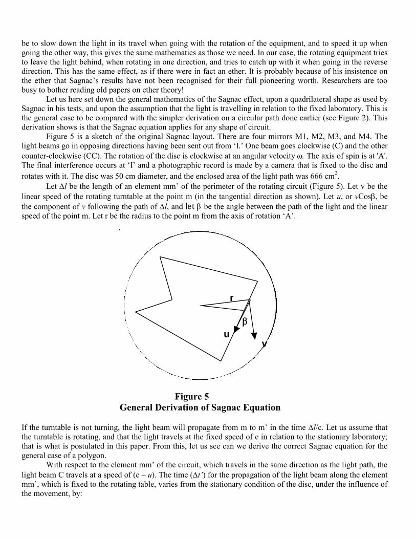
Figure 5 is a sketch of the original Sagnac layout. There are four mirrors M1, M2, M3, and M4. The
light beams go in opposing directions having been sent out from ‘I.’ One beam goes clockwise (C) and the other
counter-clockwise (CC). The rotation of the disc is clockwise at an angular velocity The axis of spin is at 'A'.
The final interference occurs at ‘I’ and a photographic record is made by a camera that is fixed to the disc and
rotates with it. The disc was 50 cm diameter, and the enclosed area of the light path was 666 cm2.
Let l be the length of an element mm’ of the perimeter of the rotating circuit (Figure 5). Let v be the
linear speed of the rotating turntable at the point m (in the tangential direction as shown). Let u, or vCosbe
the component of v following the path of l, and let be the angle between the path of the light and the linear
speed of the point m. Let r be the radius to the point m from the axis of rotation ‘A’.
vu
r m
m’
A
M2
M1
M3
M4
I
C
CC
Figure 5
General Derivation of Sagnac Equation
If the turntable is not turning, the light beam will propagate from m to m’ in the time l/c. Let us assume that
the turntable is rotating, and that the light travels at the fixed speed of c in relation to the stationary laboratory;
that is what is postulated in this paper. From this, let us see can we derive the correct Sagnac equation for the
general case of a polygon.
With respect to the element mm’ of the circuit, which travels in the same direction as the light path, the
light beam C travels at a speed of (c – u). The time (t‟) for the propagation of the light beam along the element
mm’, which is fixed to the rotating table, varies from the stationary condition of the disc, under the influence of
the movement, by:
t‟ = l/[c – u] – [l/c] = l/c[(c)/(c – u) –1]
Expanding c/(c – u), by the Binomial Theorem,
which in general is (1 + x)n = 1 + (n)(x) + [n(n – 1)/2!][x
2] + etc.
we get [(c – u)/c] 1
=
[1 – u/c]-1
= 1 + (– 1)(– u/c) + {[(– 1)(– 2)]/[2]}{( – u/c)2} + smaller terms.
= 1 + u/c + (u/c)2 + smaller terms.
Substituting this back above, we get
t‟ = [l/c][u/c] + [l/c][u/c]2 + smaller terms.
For the beam that goes in the other direction (CC) we get similarly
t” = – [l/c][u/c] + [l/c][u/c]2
+ smaller terms.
When we calculate the difference in the times to go clockwise (t‟) and anticlockwise (t”), the second order
terms cancel; subtracting we get 2t = 2[l/c][u/c], without neglecting terms of the second order, but neglecting
only terms of the third and higher orders. So, the delay over the distance mm’ of the light C in relation to the
light CC, is
t = 2ul/c2
By putting the integral of ul = D, we find the total delay for the whole circuit to be t = 2D/c2. This t is the
average of the two time differences t‟ and t”, which in turn are the differences between the stationary time
for light to traverse the element mm’, and the times to traverse that element when the table is rotating in the two
directions. Hence we have the factor of 2 applied.
We have u = rCos and dl = rd/Cos calling d the angle at which an element mm’ is infinitely
small, as seen from the axis of rotation (A) in the plane of the circuit. Let d be the area of the triangle Amm’,
with the element mm’ rendered infinitely small. The element of delay of the light beam has a value udl
r2ddthis follows from e.g. a quadrant of a circle gives an angle of and an Area of r
2/4; this
Area = r2/2 The total delay over the complete circuit is D = 2A = 4nA, where n is the number of rotations
per second, and A is the total area enclosed by the path of the light beams. The total difference in time for the
two beams C and CC to complete a circuit in opposing directions is 2t = 2D/c2 = [8nA][c
2], which is the
Sagnac formula
t = 4Ac2
We have proved that for a general configuration of the Sagnac experiment, and on the assumption that
light travels with respect to the fixed laboratory, the difference in time for two beams going in opposing
directions to traverse the light path is the Sagnac formula.
To synopsize, the facts of the Sagnac tests are as follows:
1. The light beams are in synchronism when released.
2. The light beams are not in synchronism when they have completed one turn of the apparatus.
3. Any observer on board the rotating apparatus, or stationary in the laboratory, will observe identical
fringe shifts. If the observer is in the laboratory, there would be a very small Doppler effect when observing the
moving apparatus, but, this is insignificant and will not make any observable difference to the result. There was
no Doppler effect whatever, in the original Sagnac test, because the observations were made aboard the
spinning disc, and the observation point was at a constant distance from the point of interference.
4. The light is behaving as if it were travelling at constant speed relative to the laboratory. It ignores the
spinning of the apparatus. The light does not travel at a constant speed relative to the observer aboard that
spinning apparatus. As seen from the mathematical derivation from Figure 2, the light does not go at a speed of
c with respect to the observer upon the spinning apparatus. Going in one direction, it measures as going slower
than c, and going in the other direction it measures as going at a speed higher than c.
5. Time and distance aboard a spinning disc are identical with time and distance in the stationary
laboratory. They are also identical aboard an object that is moving at uniform velocity in a straight line.
Conclusion
The Sagnac effect applies to uniform straight-line motion, just as it does to rotational motion.
References
[1] M. G. Sagnac, Compt. Rend. 157, 708-10 & 1410-13 (1913); J. de Phys. 5th Ser.1914 4, 177-95 (1914).
[2] E. J. Post, Phys. Rev. Lett., 15 No 5, 177-8 (1965); Rev. Mod. Phys. 39 No.2, 475-93 (1967).
[3] A. Dufour & F. Prunier, Compt.Rend., 204, 1332-4 & 1925-27 (1937); 205, 658-9, 208, 988-90, (1939);
212, 153-4. (1941); J. de Phys., 3 No 9, 153-61 (1942).
[4] D. C. Miller, Am. Phys. Soc., 19 No 4, 407-8 (1921).
[5] L. J. Silberstein, J. Op. Soc. Am., 5 No 4, 291-307 (1921).
[6] A. A. Michelson & H. G. Gale, Nature, 115 No 2894, 566 (1925).
[7] D. Turner & R. Hazlett R. (ed), Einstein Myth and the Ives Papers (Devin-Adair) (1979).
[8] A. A. Michelson, Phil Mag. S6-8 No 48, 716-9 (1904).
[9] A. A. Michelson Astroph. J. 37,190-3 (1913).
[10] W. M. Macek & D. T. M. Davis, App. Phys. Lett. 2 No 3, 67-8 (1963).
[11] Bilger H R et al., IEEE Trans, IM 42 No 2, 407-11 (1993); IM 44 No2, 468-70 (1995).
[12] R. Anderson et al., Am. J. Phys., 62 (11), 975-85 (1994).
[13] G. J. Martin, IEEE Spect. 48-53 (1986).
[14] D. Z. Anderson, Scientific Amer, 254, 86-91, (1986).
[15] A. Einstein Ann. der Phys. 1905, 17, 891-921 (1905).
[16] H. D. Young & R. A. Freedman University Physics (Addison-Wesley; N.Y.) (1996).
[17] F. Harress, Thesis (unpublished), Jena (1911).
[18] B. Pogany, Ann. Phys. 4 No.11, Band 80, 217-31 (1926); S4, 85, 244-51 (1928).
[19] A Einstein, Ann. Phys. 49, 111-164 (1916) translation of 1905 & 1916 papers by Perrett & Jeffery in
The Principle of Relativity (Dover) (1952).
[20] CCDS 9th session, S15-17 (1980).
[21] CCIR Internat. Telecom. Union, Internat. Radio Consult Comm. Report Annex to Vol. 7 No.439-5,
Geneva, 150-54 (1990); ITU-R No TF 1010-1 (1997).
[22] J. C. Haffle & R. E. Keating, Science, 177, 166-7 & 168-70 (1972).
[23] R. Wang et al. Phys. Lett A, 312, 7-10 (2003).
[24] A. G. Kelly, Infinite Energy 2001, 39, 24-28 (2001).