Embed Size (px)
Citation preview
22 The Arup Journal 3/2008
Background
Toronto’s original Museum of Natural History and Fine Arts opened in 1857 at the Toronto Normal School (“normal school” is a now little-used term for a teacher-training college). The enactment of the Royal Ontario Museum Act by the provincial government in 1912 re-established the museum as the Royal Ontario Museum (ROM), with a new building designed by Toronto architects Frank Darling and John A Pearson in the then-fashionable Italianate neo-Romanesque style.
This opened in March 1914, since when the ROM has undergone three major expansions. In 1933 the first of these added an east wing fronting onto Queen’s Park, including an elaborate art deco Byzantine-inspired rotunda and new main entrance. Both this wing, designed by Alfred H Chapman and James Oxley, and the original building are listed as heritage buildings of Toronto.
The Royal Ontario Museum, Toronto
The Crystal extension designed by Daniel Libeskind is a spectacular and iconic new building for Toronto.
Florence Lam David Lewis Julian Sutherland
1. Architect’s concept of the “Crystal” extension within the existing museum.
2. Original “napkin sketch” by Daniel Libeskind.
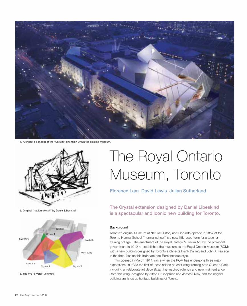
3. The five “crystal” volumes.
3. Main structural frame from GSACrystal 1Crystal 3
East Wing
West Wing
Crystal 2
Crystal 5
Crystal 4
Central
23The Arup Journal 3/2008
Situated on one of the most prominent intersections in downtown Toronto, the Crystal established itself as a dynamic centre for the city when it opened in June 2007.
Arup, working with local engineering consultants, was appointed to engineer the architectural vision, the scope of which also included renovating 10 galleries in the existing buildings on either side of the Crystal.
Structural engineering
Methodology
Libeskind’s buildings are well known for their unusual shapes, and the challenge to the Arup team to form the structure started at the competition stage, a challenge heightened by the desire to insert the new construction within the form of the original buildings and match to their existing floors.
On earlier projects with Libeskind, such as the Imperial War Museum North in Manchester, England, a joint working methodology had been established using 3-D programs such as Form Z, Rhino, and Arup’s own GSA to enable rapid transfer of information between architect and engineer. For the ROM, this provided a base structural concept and graphics for the competition entry. By demonstrating to the client and his technical team how the work would be carried out, the 3-D modelling was vital to securing the commission.
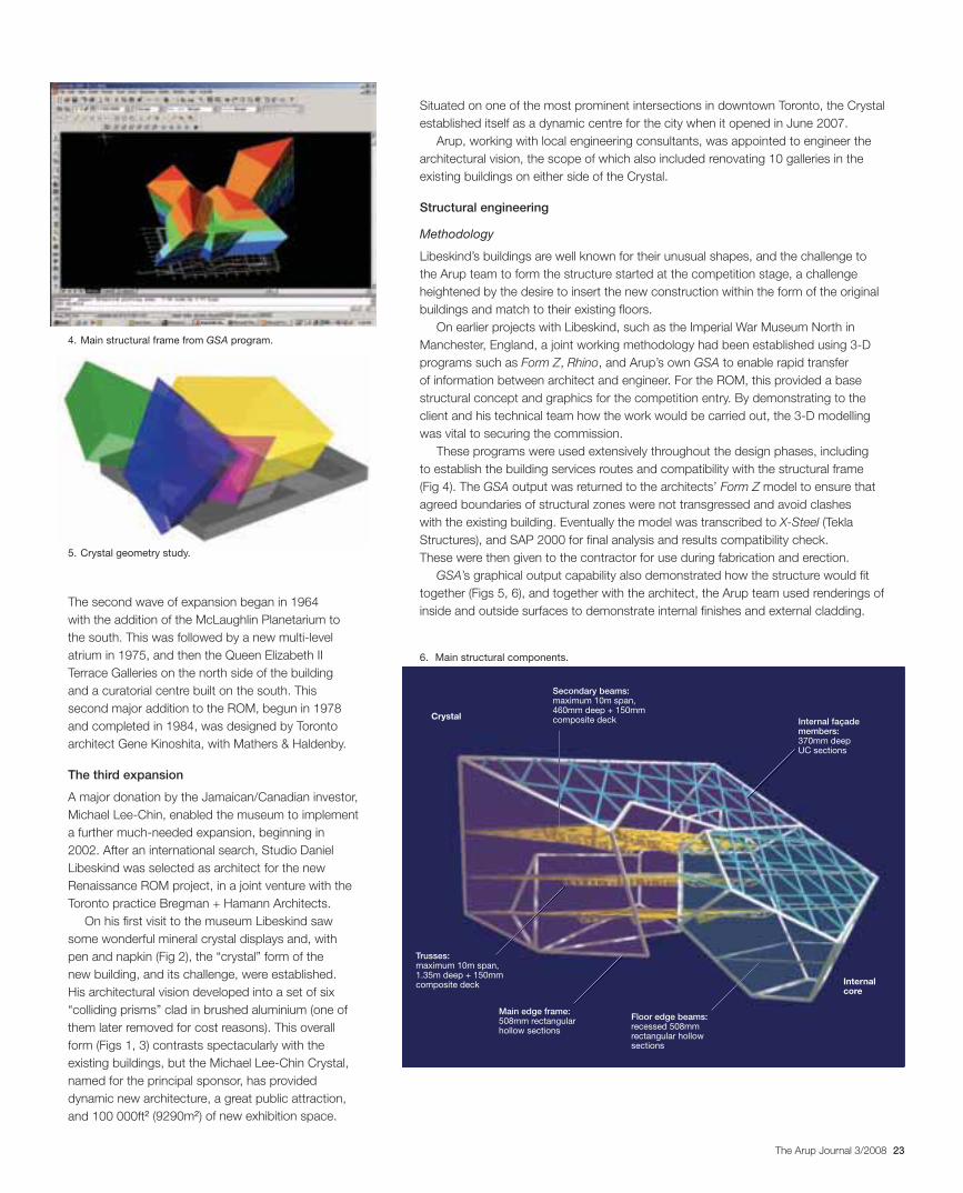
These programs were used extensively throughout the design phases, including to establish the building services routes and compatibility with the structural frame (Fig 4). The GSA output was returned to the architects’ Form Z model to ensure that agreed boundaries of structural zones were not transgressed and avoid clashes with the existing building. Eventually the model was transcribed to X-Steel (Tekla Structures), and SAP 2000 for final analysis and results compatibility check. These were then given to the contractor for use during fabrication and erection.
GSA’s graphical output capability also demonstrated how the structure would fit together (Figs 5, 6), and together with the architect, the Arup team used renderings of inside and outside surfaces to demonstrate internal finishes and external cladding.
The second wave of expansion began in 1964 with the addition of the McLaughlin Planetarium to the south. This was followed by a new multi-level atrium in 1975, and then the Queen Elizabeth II Terrace Galleries on the north side of the building and a curatorial centre built on the south. This second major addition to the ROM, begun in 1978 and completed in 1984, was designed by Toronto architect Gene Kinoshita, with Mathers & Haldenby.
The third expansion
A major donation by the Jamaican/Canadian investor, Michael Lee-Chin, enabled the museum to implement a further much-needed expansion, beginning in 2002. After an international search, Studio Daniel Libeskind was selected as architect for the new Renaissance ROM project, in a joint venture with the Toronto practice Bregman + Hamann Architects.
On his first visit to the museum Libeskind saw some wonderful mineral crystal displays and, with pen and napkin (Fig 2), the “crystal” form of the new building, and its challenge, were established. His architectural vision developed into a set of six “colliding prisms” clad in brushed aluminium (one of them later removed for cost reasons). This overall form (Figs 1, 3) contrasts spectacularly with the existing buildings, but the Michael Lee-Chin Crystal, named for the principal sponsor, has provided dynamic new architecture, a great public attraction, and 100 000ft2 (9290m2) of new exhibition space.
4. Main structural frame from GSA program.
5. Crystal geometry study.
6. Main structural components.
Internal façade members: 370mm deep UC sections
Crystal
Internal core
Secondary beams: maximum 10m span, 460mm deep + 150mm composite deck
Trusses: maximum 10m span, 1.35m deep + 150mm composite deck
Main edge frame: 508mm rectangular hollow sections
Floor edge beams: recessed 508mm rectangular hollow sections
24 The Arup Journal 3/2008
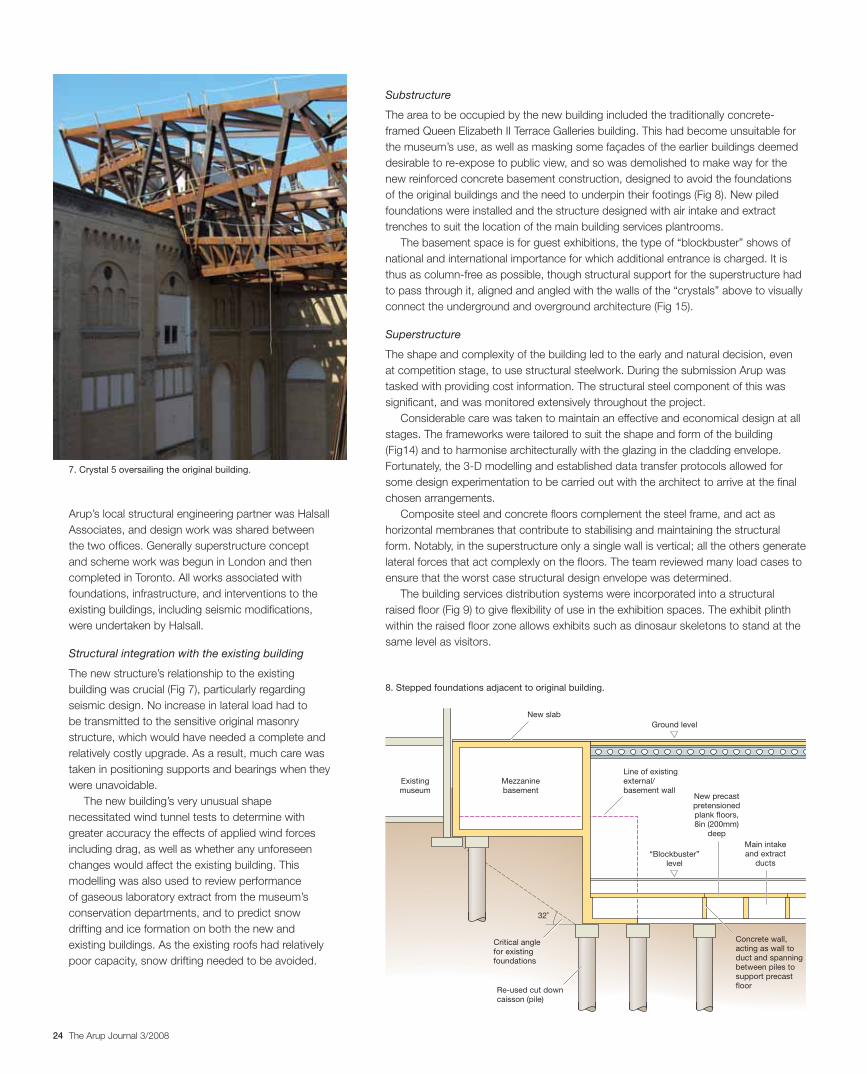
Substructure
The area to be occupied by the new building included the traditionally concrete-framed Queen Elizabeth II Terrace Galleries building. This had become unsuitable for the museum’s use, as well as masking some façades of the earlier buildings deemed desirable to re-expose to public view, and so was demolished to make way for the new reinforced concrete basement construction, designed to avoid the foundations of the original buildings and the need to underpin their footings (Fig 8). New piled foundations were installed and the structure designed with air intake and extract trenches to suit the location of the main building services plantrooms.
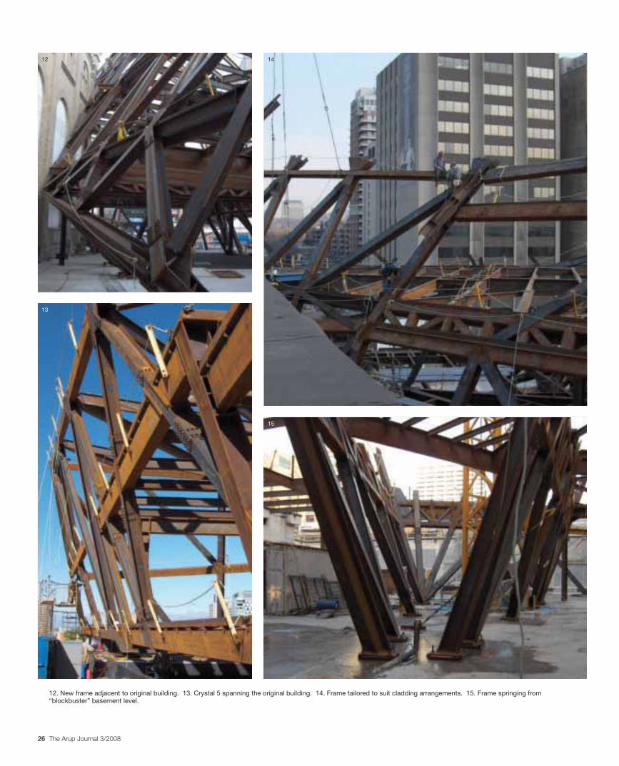
The basement space is for guest exhibitions, the type of “blockbuster” shows of national and international importance for which additional entrance is charged. It is thus as column-free as possible, though structural support for the superstructure had to pass through it, aligned and angled with the walls of the “crystals” above to visually connect the underground and overground architecture (Fig 15).
Superstructure
The shape and complexity of the building led to the early and natural decision, even at competition stage, to use structural steelwork. During the submission Arup was tasked with providing cost information. The structural steel component of this was significant, and was monitored extensively throughout the project.
Considerable care was taken to maintain an effective and economical design at all stages. The frameworks were tailored to suit the shape and form of the building (Fig14) and to harmonise architecturally with the glazing in the cladding envelope. Fortunately, the 3-D modelling and established data transfer protocols allowed for some design experimentation to be carried out with the architect to arrive at the final chosen arrangements.
Composite steel and concrete floors complement the steel frame, and act as horizontal membranes that contribute to stabilising and maintaining the structural form. Notably, in the superstructure only a single wall is vertical; all the others generate lateral forces that act complexly on the floors. The team reviewed many load cases to ensure that the worst case structural design envelope was determined.
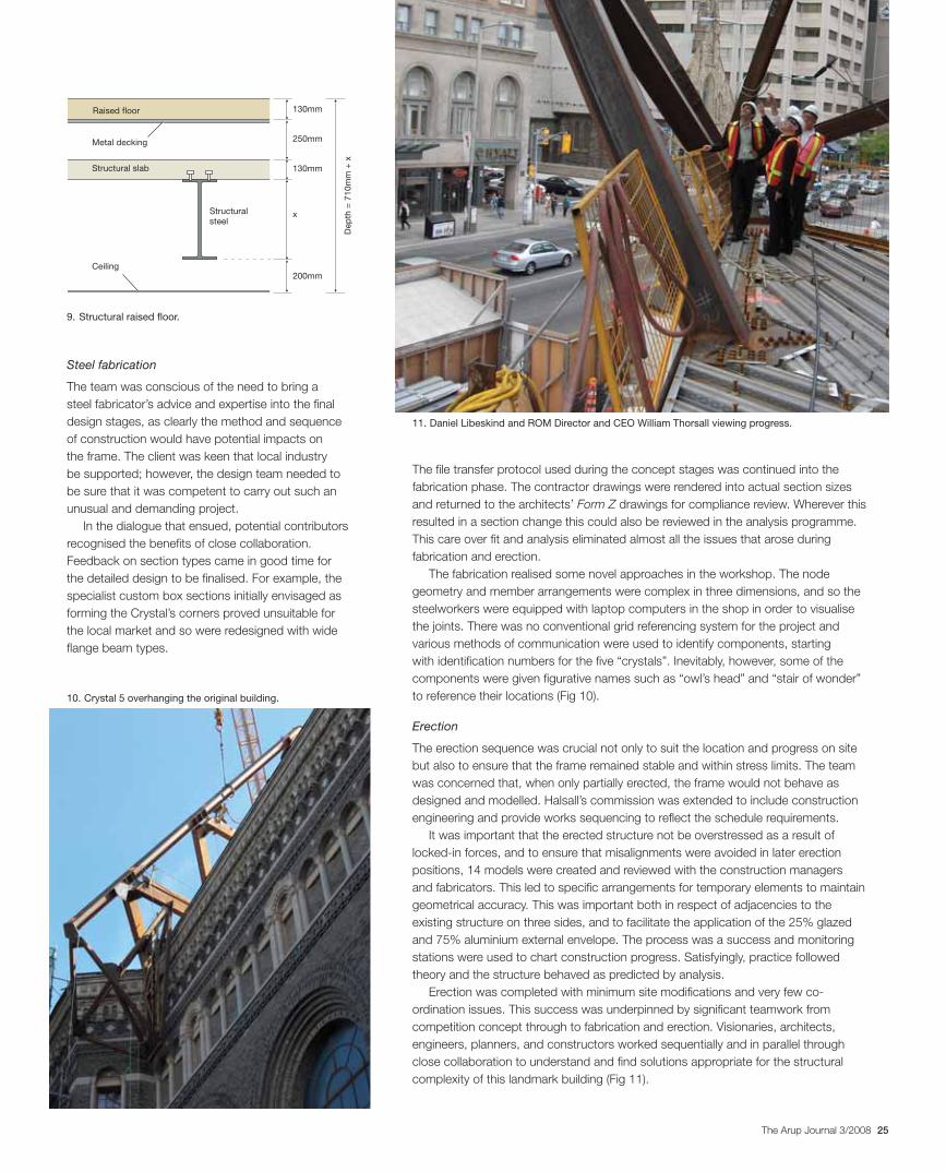
The building services distribution systems were incorporated into a structural raised floor (Fig 9) to give flexibility of use in the exhibition spaces. The exhibit plinth within the raised floor zone allows exhibits such as dinosaur skeletons to stand at the same level as visitors.
Arup’s local structural engineering partner was Halsall Associates, and design work was shared between the two offices. Generally superstructure concept and scheme work was begun in London and then completed in Toronto. All works associated with foundations, infrastructure, and interventions to the existing buildings, including seismic modifications, were undertaken by Halsall.
Structural integration with the existing building
The new structure’s relationship to the existing building was crucial (Fig 7), particularly regarding seismic design. No increase in lateral load had to be transmitted to the sensitive original masonry structure, which would have needed a complete and relatively costly upgrade. As a result, much care was taken in positioning supports and bearings when they were unavoidable.
The new building’s very unusual shape necessitated wind tunnel tests to determine with greater accuracy the effects of applied wind forces including drag, as well as whether any unforeseen changes would affect the existing building. This modelling was also used to review performance of gaseous laboratory extract from the museum’s conservation departments, and to predict snow drifting and ice formation on both the new and existing buildings. As the existing roofs had relatively poor capacity, snow drifting needed to be avoided.
Existingmuseum
New slab
Mezzaninebasement
Ground level
Line of existing external/basement wall
New precastpretensionedplank floors,8in (200mm)
deepMain intakeand extract
ducts
Concrete wall,acting as wall toduct and spanning between piles to support precastfloor
“Blockbuster”level
32˚
Critical angle for existing foundations
Re-used cut down caisson (pile)
7. Crystal 5 oversailing the original building.
8. Stepped foundations adjacent to original building.
25The Arup Journal 3/2008
Steel fabrication
The team was conscious of the need to bring a steel fabricator’s advice and expertise into the final design stages, as clearly the method and sequence of construction would have potential impacts on the frame. The client was keen that local industry be supported; however, the design team needed to be sure that it was competent to carry out such an unusual and demanding project.
In the dialogue that ensued, potential contributors recognised the benefits of close collaboration. Feedback on section types came in good time for the detailed design to be finalised. For example, the specialist custom box sections initially envisaged as forming the Crystal’s corners proved unsuitable for the local market and so were redesigned with wide flange beam types.
The file transfer protocol used during the concept stages was continued into the fabrication phase. The contractor drawings were rendered into actual section sizes and returned to the architects’ Form Z drawings for compliance review. Wherever this resulted in a section change this could also be reviewed in the analysis programme. This care over fit and analysis eliminated almost all the issues that arose during fabrication and erection.
The fabrication realised some novel approaches in the workshop. The node geometry and member arrangements were complex in three dimensions, and so the steelworkers were equipped with laptop computers in the shop in order to visualise the joints. There was no conventional grid referencing system for the project and various methods of communication were used to identify components, starting with identification numbers for the five “crystals”. Inevitably, however, some of the components were given figurative names such as “owl’s head” and “stair of wonder” to reference their locations (Fig 10).
Erection
The erection sequence was crucial not only to suit the location and progress on site but also to ensure that the frame remained stable and within stress limits. The team was concerned that, when only partially erected, the frame would not behave as designed and modelled. Halsall’s commission was extended to include construction engineering and provide works sequencing to reflect the schedule requirements.
It was important that the erected structure not be overstressed as a result of locked-in forces, and to ensure that misalignments were avoided in later erection positions, 14 models were created and reviewed with the construction managers and fabricators. This led to specific arrangements for temporary elements to maintain geometrical accuracy. This was important both in respect of adjacencies to the existing structure on three sides, and to facilitate the application of the 25% glazed and 75% aluminium external envelope. The process was a success and monitoring stations were used to chart construction progress. Satisfyingly, practice followed theory and the structure behaved as predicted by analysis.
Erection was completed with minimum site modifications and very few co-ordination issues. This success was underpinned by significant teamwork from competition concept through to fabrication and erection. Visionaries, architects, engineers, planners, and constructors worked sequentially and in parallel through close collaboration to understand and find solutions appropriate for the structural complexity of this landmark building (Fig 11).
Dep
th =
710
mm
+ x
Raised floor
Metal decking
Structural slab
Ceiling
Structuralsteel
130mm
250mm
130mm
x
200mm
10. Crystal 5 overhanging the original building.
9. Structural raised floor.
11. Daniel Libeskind and ROM Director and CEO William Thorsall viewing progress.
26 The Arup Journal 3/2008
12. New frame adjacent to original building. 13. Crystal 5 spanning the original building. 14. Frame tailored to suit cladding arrangements. 15. Frame springing from “blockbuster” basement level.
12
13
14
15
27The Arup Journal 3/2008
The Level 4 galleries are environmentally separate from the other Crystal galleries and the existing galleries, allowing close control of temperature and humidity. Their daylit environment enhances the visitor experience, and careful analysis of the windows and resulting solar exposure ensures that artefacts are protected accordingly.
The other Crystal galleries and the existing galleries are interconnected for obstruction-free visitor circulation. The design conditions were limited by the heritage status building fabric, which struggles to control vapour, infiltration, and thermal exchange. Minor repair work was undertaken to improve the fabric performance with secondary glazing and vapour barriers.
Where it is necessary for temperature, humidity, and light to be very closely controlled in any gallery, discrete closed cases are used. These are integrated into the design of the galleries with their dedicated plant housed in local plantrooms.
Energy efficiency
Maintaining energy efficiency within a curatorial environment is difficult, but by careful selection of systems, components, controls, and space links it is possible to recover energy and reduce waste. Arup included energy recovery on all the new ventilation systems using both active and passive technologies:
the “blockbuster” floor by heat energy transfer through the tunnel walls)
Crystal galleries ventilation design
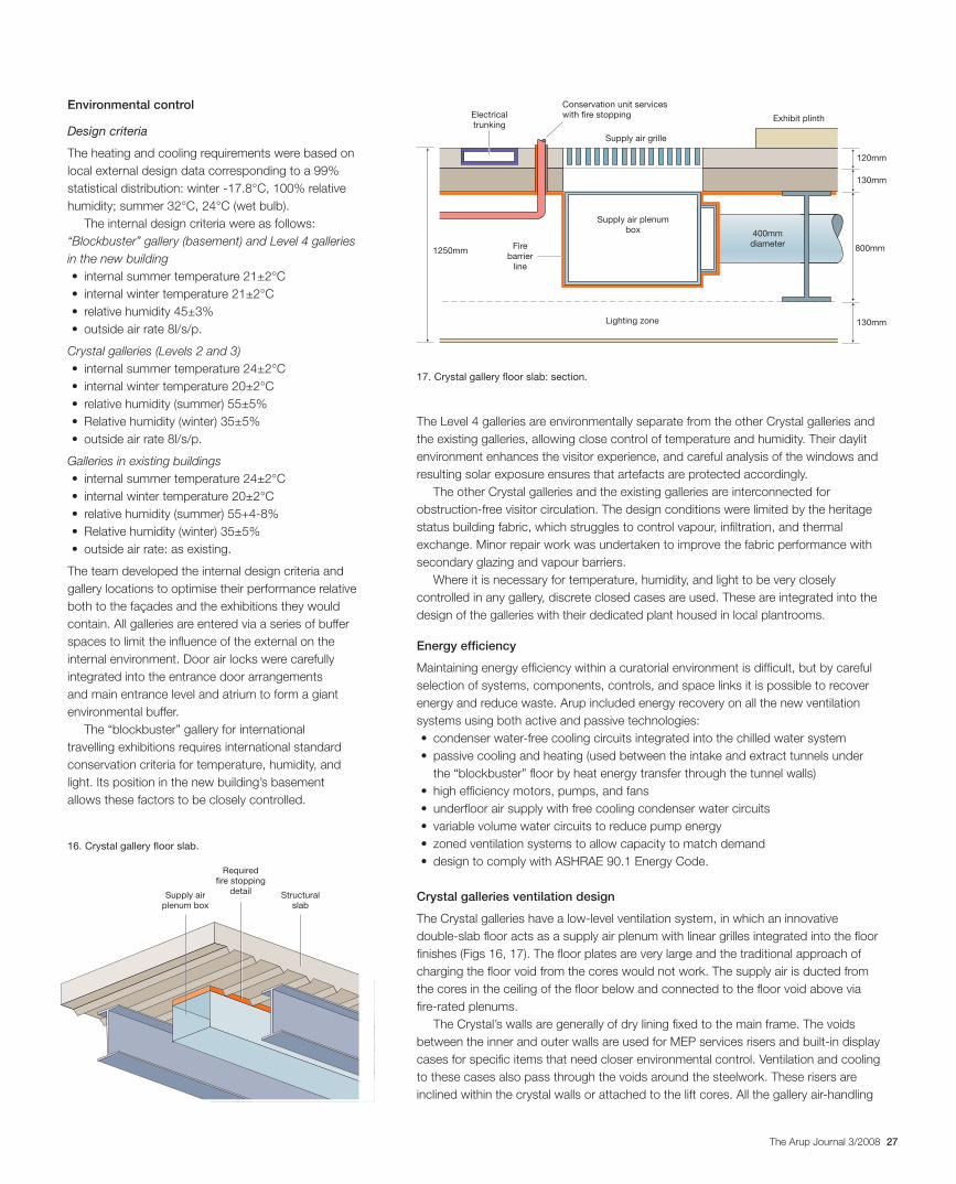
The Crystal galleries have a low-level ventilation system, in which an innovative double-slab floor acts as a supply air plenum with linear grilles integrated into the floor finishes (Figs 16, 17). The floor plates are very large and the traditional approach of charging the floor void from the cores would not work. The supply air is ducted from the cores in the ceiling of the floor below and connected to the floor void above via fire-rated plenums.
The Crystal’s walls are generally of dry lining fixed to the main frame. The voids between the inner and outer walls are used for MEP services risers and built-in display cases for specific items that need closer environmental control. Ventilation and cooling to these cases also pass through the voids around the steelwork. These risers are inclined within the crystal walls or attached to the lift cores. All the gallery air-handling
Environmental control
Design criteria
The heating and cooling requirements were based on local external design data corresponding to a 99% statistical distribution: winter -17.8°C, 100% relative humidity; summer 32°C, 24°C (wet bulb).
The internal design criteria were as follows:“Blockbuster” gallery (basement) and Level 4 galleries in the new building
Crystal galleries (Levels 2 and 3)
Galleries in existing buildings
The team developed the internal design criteria and gallery locations to optimise their performance relative both to the façades and the exhibitions they would contain. All galleries are entered via a series of buffer spaces to limit the influence of the external on the internal environment. Door air locks were carefully integrated into the entrance door arrangements and main entrance level and atrium to form a giant environmental buffer.
The “blockbuster” gallery for international travelling exhibitions requires international standard conservation criteria for temperature, humidity, and light. Its position in the new building’s basement allows these factors to be closely controlled.
Electricaltrunking
Supply air grille
Exhibit plinth
Supply air plenum box 400mm
diameter
Lighting zone
Firebarrier
line
130mm
120mm
130mm
1250mm 800mm
Conservation unit services with fire stopping
Structuralslab
Requiredfire stopping
detailSupply air plenum box
16. Crystal gallery floor slab.
17. Crystal gallery floor slab: section.
28 The Arup Journal 3/2008
As the development was within an operational museum, so the replacement also had to be done alongside and link into the existing operation. Careful phasing of the basement refurbishment allowed a new chilled water plantroom to be created.
The new plant was installed and a new section of cooling tower was fitted to match the increased load and system. All this was commissioned and brought on line before the existing plant was decommissioned, the old plantroom subsequently being refurbished for storage.
The gallery compartment AHUs that were already located with each wing and level of the existing building were surveyed and maintained to increase their operating life.
The new Crystal gallery plant is in the basement of the central wing of the existing building, a location unusable for gallery functions but connecting well into the Crystal gallery construction. The team investigated ways to get outdoor and exhaust air to this location, but most of them compromised gallery space or had high construction costs. The final solution was to take the main intake and exhaust entirely under the Crystal gallery construction and integrate the louvres with the “blockbuster” gallery plantroom in the north-east corner of the site.
units (AHUs) are fitted with dual cooling coils to offer significant energy savings, each AHU having equal-sized cooling coils in parallel controlled in sequence either singularly or as a pair. This operation allows dehumidification to match part loads in the museum without the huge corresponding reheating load of a single coil system.
A perimeter heating system, integrated into the façade floor trims, offsets draughts and local thermal losses at the windows.
Façade and thermal envelope
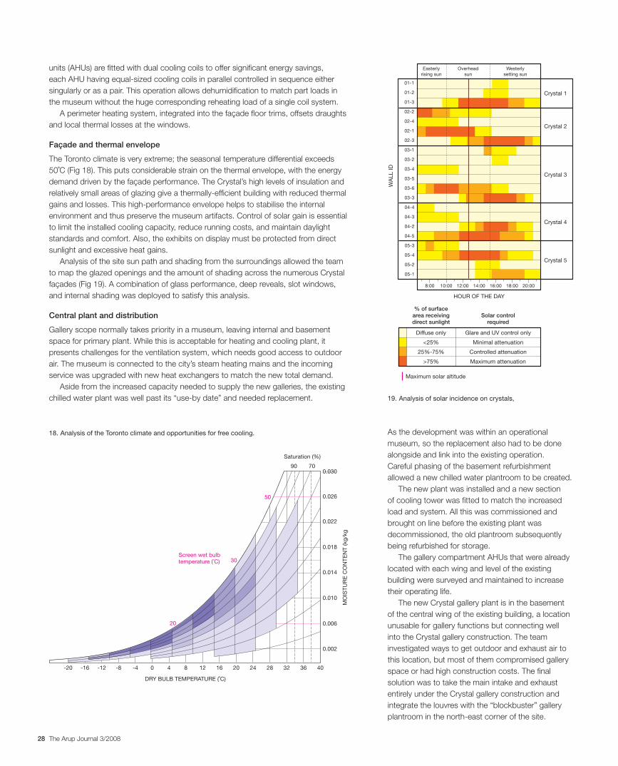
The Toronto climate is very extreme; the seasonal temperature differential exceeds 50˚C (Fig 18). This puts considerable strain on the thermal envelope, with the energy demand driven by the façade performance. The Crystal’s high levels of insulation and relatively small areas of glazing give a thermally-efficient building with reduced thermal gains and losses. This high-performance envelope helps to stabilise the internal environment and thus preserve the museum artifacts. Control of solar gain is essential to limit the installed cooling capacity, reduce running costs, and maintain daylight standards and comfort. Also, the exhibits on display must be protected from direct sunlight and excessive heat gains.
Analysis of the site sun path and shading from the surroundings allowed the team to map the glazed openings and the amount of shading across the numerous Crystal façades (Fig 19). A combination of glass performance, deep reveals, slot windows, and internal shading was deployed to satisfy this analysis.
Central plant and distribution
Gallery scope normally takes priority in a museum, leaving internal and basement space for primary plant. While this is acceptable for heating and cooling plant, it presents challenges for the ventilation system, which needs good access to outdoor air. The museum is connected to the city’s steam heating mains and the incoming service was upgraded with new heat exchangers to match the new total demand.
Aside from the increased capacity needed to supply the new galleries, the existing chilled water plant was well past its “use-by date” and needed replacement.
MO
ISTU
RE
CO
NTE
NT
(kg/
kg
Saturation (%)
90 70
Screen wet bulb temperature (˚C)
50
0.030
0.026
0.022
0.018
0.014
0.010
0.006
0.002
4036322824201612840-4-8-12-16-20
30
20
DRY BULB TEMPERATURE (˚C)
18. Analysis of the Toronto climate and opportunities for free cooling.
Crystal 1
Crystal 2
Crystal 3
Crystal 4
Crystal 5
8:00 10:00 12:00 14:00 16:00 18:00 20:00
HOUR OF THE DAY
WA
LL ID
01-1
01-2
01-3
02-2
02-4
02-1
02-3
03-1
03-2
03-4
03-5
03-6
03-3
04-4
04-3
04-2
04-5
05-3
05-4
05-2
05-1
Easterly rising sun
Overheadsun
Westerlysetting sun
Diffuse only
<25%
25%-75%
>75%
Glare and UV control only
Minimal attenuation
Controlled attenuation
Maximum attenuation
% of surface area receivingdirect sunlight
Solar control required
Maximum solar altitude
19. Analysis of solar incidence on crystals,
29The Arup Journal 3/2008
The below-slab ducts, formed by folding the basement slab downwards to create a wide channel with a lightweight cover cast above, benefit from passive thermal exchange with the earth, capturing free heating and cooling when possible (Fig 22).
The Crystal gallery ventilation ductwork was then routed through the “blockbuster” ceiling/main entrance floor construction into the central risers around the Crystal void.
Stormwater design
The design of the roof drainage system presented many challenges, with ice and snow build-up even more important than water. The complex shape also presented many obstructions to the natural flow of rain and melt water.
Each Crystal surface and intersecting valley was analysed for gradient and used as the primary water drainage route. Then the edge conditions were checked for gravity-based water runoff to identify whether it would travel inwards to a gutter or outwards off the edge. If the latter, a hidden edge gutter was fitted. Finally the windows were analysed for runoff redirection and to check that there was adequate capacity for water to go around them. If there was not, the window was bisected and a rainwater channel formed between. This process generated a very simple rainwater system, albeit with a very complex geometry.
The main valley gutters also formed the primary access route for maintenance.
Snow build-up was analysed in wind tunnel tests, and where it was shown to be excessive, snow melting tapes were installed. To avoid undue energy waste, these were only fitted where absolutely necessary to control structural loads and not just to clear the roof.
Fire protection
The entire building is sprinkler-protected, and the new galleries have a zoned smoke control system with fans built into the thick Crystal walls to extract smoke based on a fire signal.
150mm slab270mm floor plenum
150mm concrete slab50mm air gap
50mm
6m1.4m
Air intake duct toplantroom
Supply airplenum supplying conditioned air to “blockbuster”gallery above
22. “Blockbuster” gallery ventilation system.
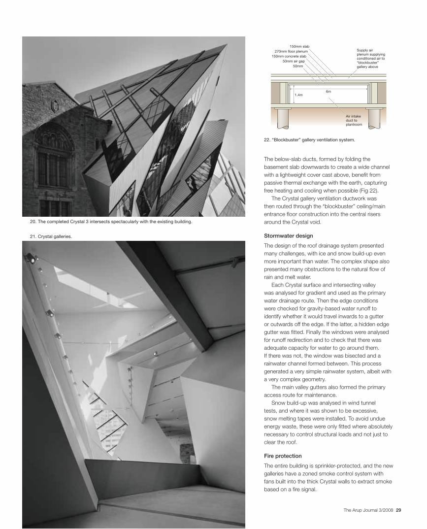
21. Crystal galleries.
20. The completed Crystal 3 intersects spectacularly with the existing building.
30 The Arup Journal 3/2008
Lighting design
Naturally daylit exhibition spaces are having a renaissance, leaving behind the black-box track-and-spotlight technique that until recently dominated US institutions. With daylight’s dynamic ever-changing nature and better colour rendering than artificial light - plus the environmental bonus of energy efficiency - the benefits are clear. Despite technological advances, the human eye will always be able to perceive the subtle qualities of a light source, and daylight is impossible to simulate convincingly. So, the move to exploit ambient natural lighting and reduce reliance on artificial light has become a preferred approach in museum design nowadays.
On this project, with the geometries set by the architect, fundamental changes were rarely made, and arguably Arup’s input might initially seem more peripheral, with less direct impact on the resultant form of the architecture. Yet, when dramatic spaces such as those created by Libeskind have to perform a practical role for exhibitions, it is essential that exhibition designers know where the daylight is throughout the year. Calculation of sunlight hours and annual exposure to daylight allows the exhibition designer and curator to be more informed in developing their display strategies.
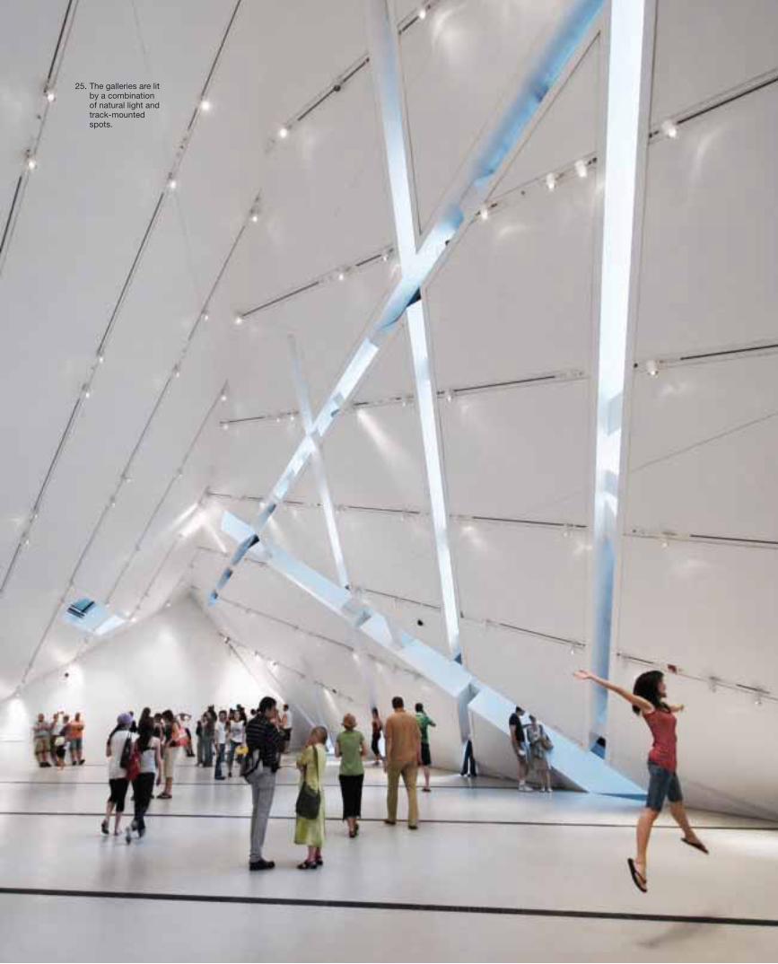
The linear “strip and field” configuration adopted for the fenestration defines the crystalline geometry of the building as well as how natural light enters the façades. It was extrapolated and developed into various forms of interior lighting scheme throughout. The approach for all the gallery suites was to provide an architectural canvas of strong graphical strip lines onto which track-mounted spots can be added to suit the exhibit configurations (Fig 25).
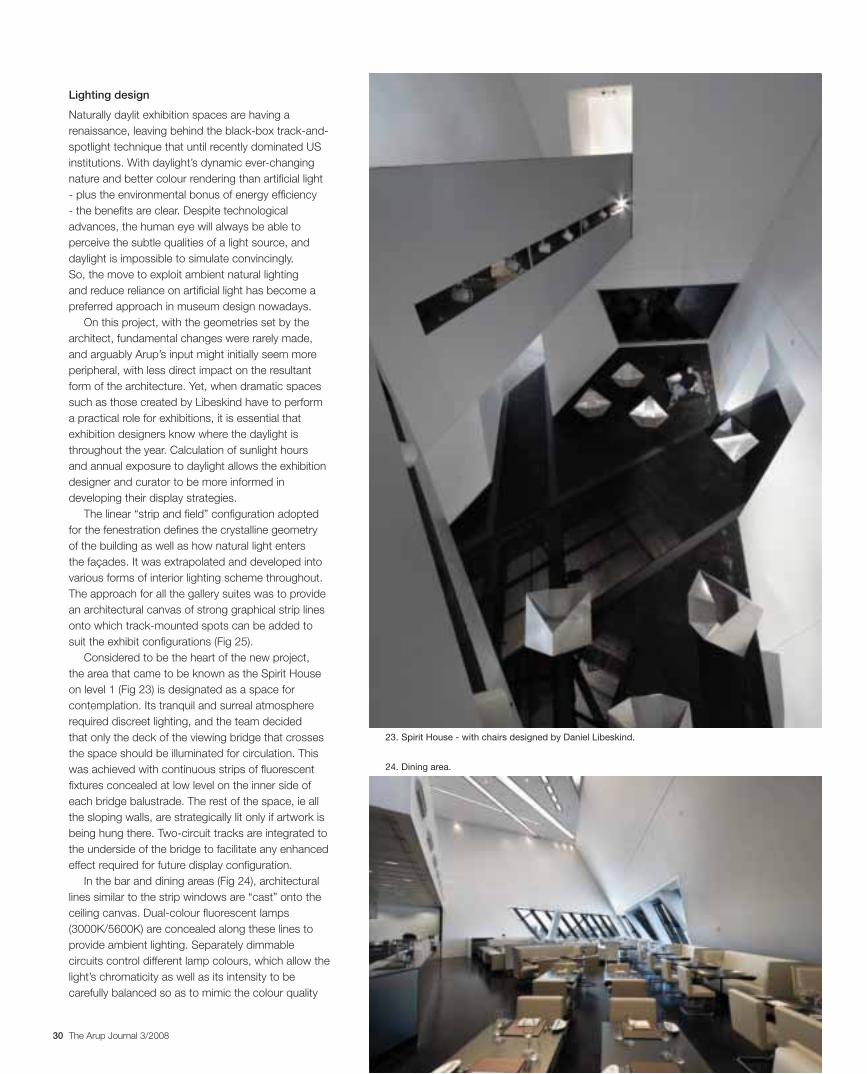
Considered to be the heart of the new project, the area that came to be known as the Spirit House on level 1 (Fig 23) is designated as a space for contemplation. Its tranquil and surreal atmosphere required discreet lighting, and the team decided that only the deck of the viewing bridge that crosses the space should be illuminated for circulation. This was achieved with continuous strips of fluorescent fixtures concealed at low level on the inner side of each bridge balustrade. The rest of the space, ie all the sloping walls, are strategically lit only if artwork is being hung there. Two-circuit tracks are integrated to the underside of the bridge to facilitate any enhanced effect required for future display configuration.
In the bar and dining areas (Fig 24), architectural lines similar to the strip windows are “cast” onto the ceiling canvas. Dual-colour fluorescent lamps (3000K/5600K) are concealed along these lines to provide ambient lighting. Separately dimmable circuits control different lamp colours, which allow the light’s chromaticity as well as its intensity to be carefully balanced so as to mimic the colour quality
24. Dining area.
23. Spirit House - with chairs designed by Daniel Libeskind.
31The Arup Journal 3/2008
25. The galleries are lit by a combination of natural light and track-mounted spots.
32 The Arup Journal 3/2008
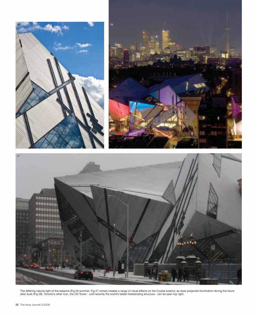
The differing natural light of the seasons (Fig 26 summer; Fig 27 winter) creates a range of visual effects on the Crystal exterior, as does projected illumination during the hours after dusk (Fig 28). Toronto’s other icon, the CN Tower - until recently the world’s tallest freestanding structure - can be seen top right.
26
27
28
33The Arup Journal 3/2008
Florence Lam is a Director of Arup and leader of the Lighting group in London. She was the principal lighting designer for the Michael Lee-Chin Crystal project.
David Lewis is a Director of Arup in the Building London group, and was Project Director for the Michael Lee-Chin Crystal project.
Julian Sutherland was formerly an Associate Director in the Building London group, and Project Manager for the Michael Lee-Chin Crystal project.
Credits
Client: Royal Ontario Museum Architect: Studio Daniel Libeskind Associate architect: Bregman+ Hamann Architects Lead SMEP engineer and lighting designer: Arup – Carolina Bartram, Daniel Bosia, Jenny Bousfield, Daniel Brace, Peter Brickell, Anna Burbidge, Mike Ebsworth, David George, Danny Hall, Tim Hanson, Tai Hollingsbee, Graham Humphreys, Karl Hurwood, Florence Lam, Bob Lau, Neil Leighton, David Lewis, Adam Martin, Paul Mosely, Natalie Rosenbaum, Sonia Samuel, Martin Self, Julian Sutherland, Glen Swinney, Karsten Thiem, Gareth Thyer, Hillary Williams, Jaime Wu Associate structural engineer: Halsall Associate
mechanical engineer: TMP Associate electrical
engineer: MBII Landscape architect: Quinn Design Associates Heritage consultant: ERA Acoustic
consultant: Valcoustics Life safety consultant: Leber/Rubes, Inc Contractor: Vanbots Construction Corporation Illustrations: 1, 2, 21, 25-27 Studio Daniel Libeskind; 3-6 Arup; 7, 10-15 Halsall; 8, 9, 16-19, 22 Nigel Whale; 20 © Stephen Evens; 19, 23, 24, 29 © Sam Javanrouh; 28 © Royal Ontario Museum.
Conclusion
The new Crystal extension by Daniel Libeskind has provided both the Royal Ontario Museum and Toronto with a superb iconic building that has fulfilled all the client’s expectations. Its facilities give the museum a platform for the future, matching its forward thinking and enabling it to maintain its position as Canada’s principal museum.
It has reinforced the ROM as a focal point for education, exhibition, and community both in and around Toronto; the restaurant in Crystal 5 is an excellent venue with superb views to the city centre.
The new building enables the curatorial staff to use exhibit display techniques not previously seen, and has raised the bar for environmental control in much of the new and original buildings. Finally it is important to recognise the generous sponsors and the leaders of the museum for their contributions needed to realise the project, together with the collaboration of the design and construction teams, vital to solving its many complex challenges.
changes of natural light throughout the day, ie the space will primarily be lit more intimately during the evening, with warmer-toned light, compared to a brighter, cooler light around midday. Supplementary feature lighting, which is integral with the bar and restaurant furniture, is also provided.
A similar common lighting design language was also adopted for the rest of the public circulation space. Arrays of bespoke light strips, comprising fluorescent lamps above a translucent ceiling scrim, provide ambience to the general circulation area including the entrance vestibules.
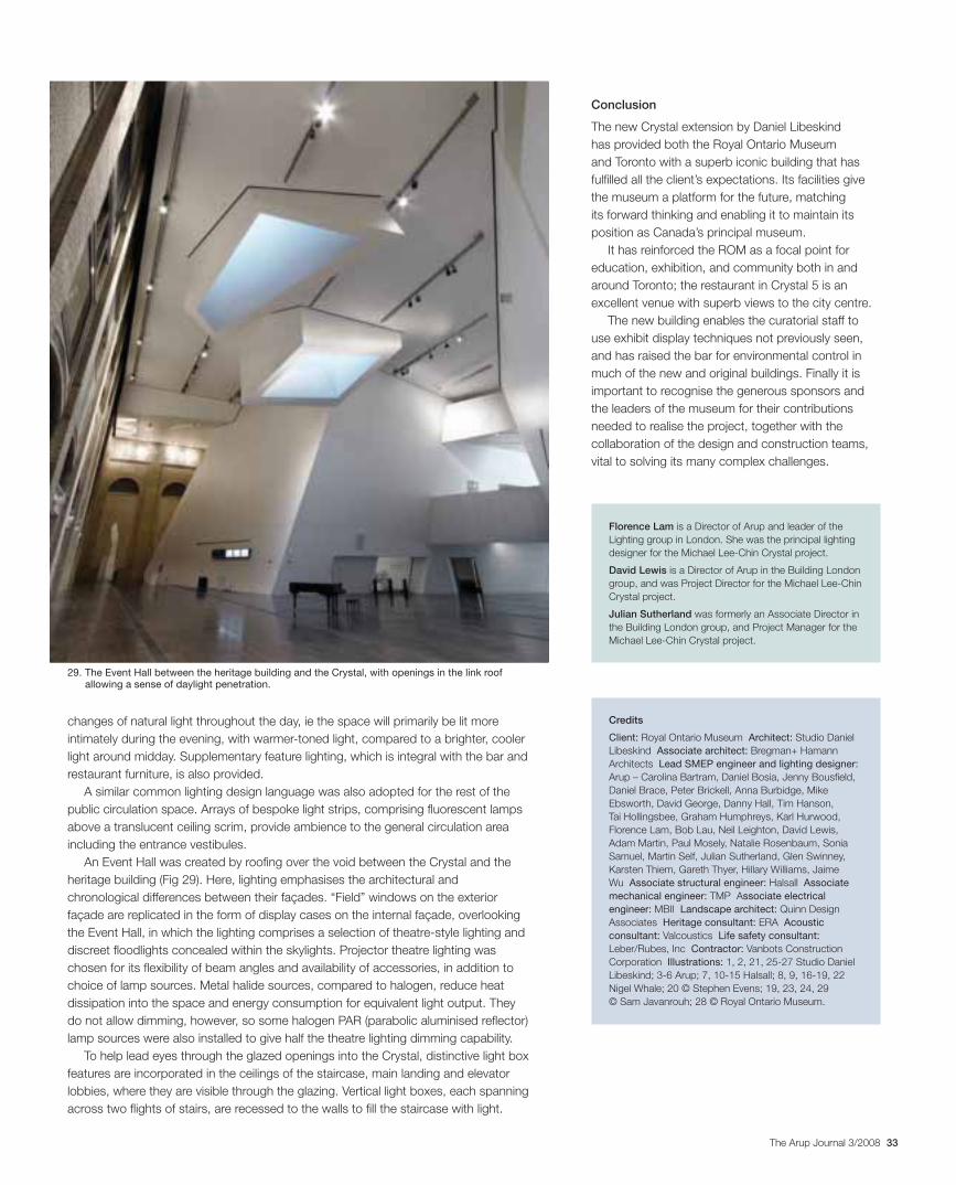
An Event Hall was created by roofing over the void between the Crystal and the heritage building (Fig 29). Here, lighting emphasises the architectural and chronological differences between their façades. “Field” windows on the exterior façade are replicated in the form of display cases on the internal façade, overlooking the Event Hall, in which the lighting comprises a selection of theatre-style lighting and discreet floodlights concealed within the skylights. Projector theatre lighting was chosen for its flexibility of beam angles and availability of accessories, in addition to choice of lamp sources. Metal halide sources, compared to halogen, reduce heat dissipation into the space and energy consumption for equivalent light output. They do not allow dimming, however, so some halogen PAR (parabolic aluminised reflector)lamp sources were also installed to give half the theatre lighting dimming capability.
To help lead eyes through the glazed openings into the Crystal, distinctive light box features are incorporated in the ceilings of the staircase, main landing and elevator lobbies, where they are visible through the glazing. Vertical light boxes, each spanning across two flights of stairs, are recessed to the walls to fill the staircase with light.
29. The Event Hall between the heritage building and the Crystal, with openings in the link roof allowing a sense of daylight penetration.