Embed Size (px)
Citation preview
The Role of the Chromosphere in Flare Energy Release
Lyndsay Fletcher
University of Glasgow
Canfield-Fest, Boulder, August 2010
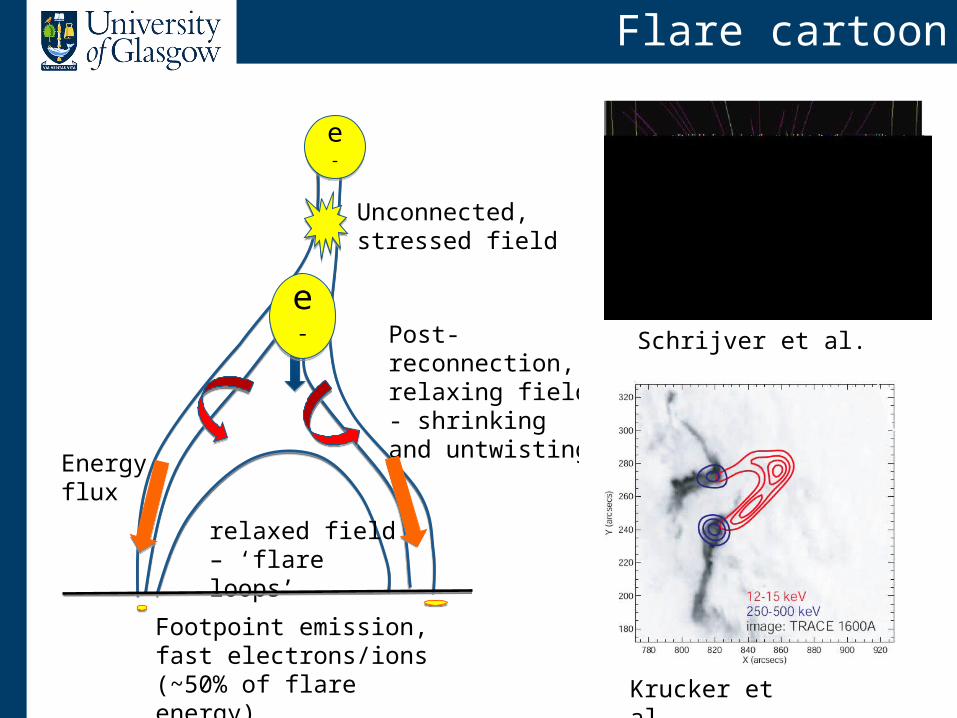
Flare cartoon
Unconnected, stressed field
relaxed field – ‘flare loops’
Post-reconnection, relaxing field- shrinking and untwisting
Energy flux
Footpoint emission, fast electrons/ions (~50% of flare energy)
e-e-
e-e-
Schrijver et al.
Krucker et al.
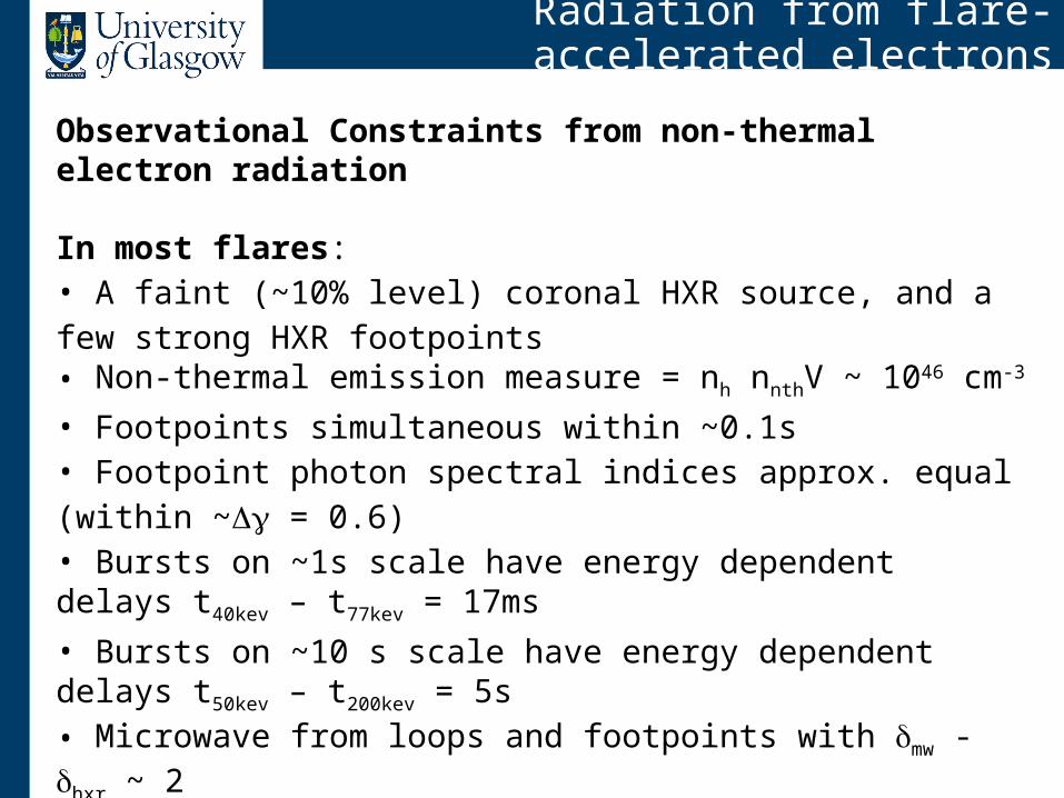
Radiation from flare-accelerated electrons
Observational Constraints from non-thermal electron radiation
In most flares: • A faint (~10% level) coronal HXR source, and a few strong HXR footpoints• Non-thermal emission measure = nh nnthV ~ 1046 cm-3 • Footpoints simultaneous within ~0.1s• Footpoint photon spectral indices approx. equal (within ~ = 0.6)• Bursts on ~1s scale have energy dependent delays t40kev – t77kev = 17ms• Bursts on ~10 s scale have energy dependent delays t50kev – t200kev = 5s• Microwave from loops and footpoints with mw - hxr ~ 2
Other types of flare can show strong coronal HXR sources (e.g. Krucker et al), or coronal loop HXR emission and no footpoints (e.g. Veronig & Brown 2004). But these are rare, as far as we know.
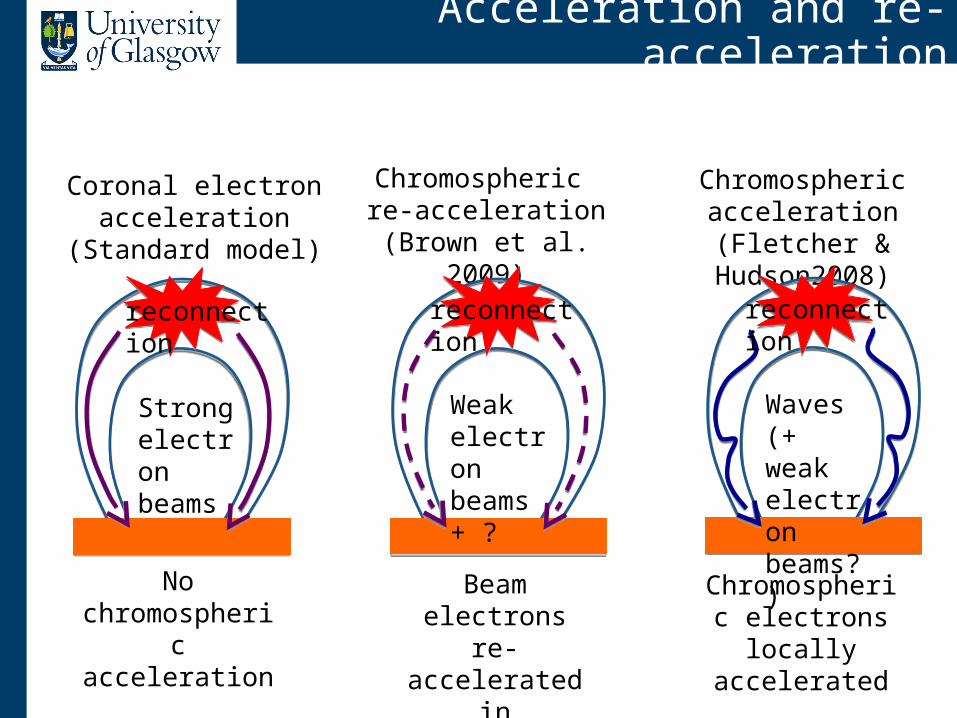
Acceleration and re-acceleration
Coronal electron acceleration (Standard
model)
Chromospheric re-acceleration
(Brown et al. 2009)
Chromospheric acceleration
(Fletcher & Hudson2008)
Strong electron beams
No chromospheric acceleration
Weak electron beams+ ?
Beam electrons re-accelerated in
chromosphere
reconnection reconnection
Waves (+ weak electron beams?)
Chromospheric electrons locally
accelerated
reconnection
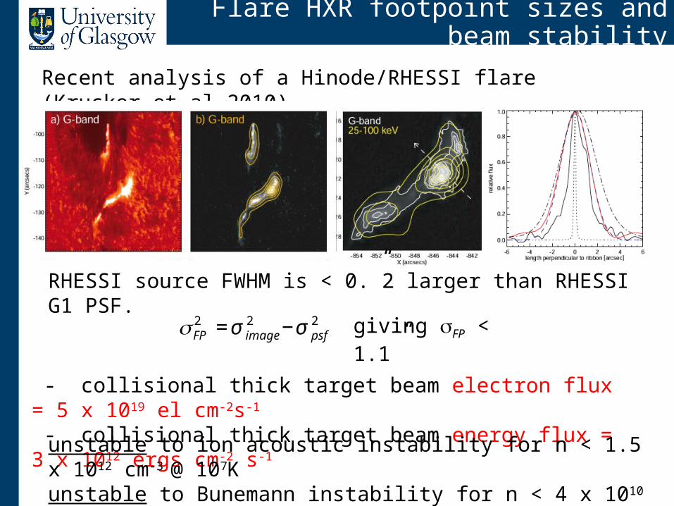
Flare HXR footpoint sizes and beam stability
Recent analysis of a Hinode/RHESSI flare (Krucker et al 2010)
RHESSI source FWHM is < 0.”2 larger than RHESSI G1 PSF.
€
σFP2 = σ image
2 −σ psf2 giving σFP < 1.1”
- collisional thick target beam electron flux = 5 x 10¹⁹ el cm-2s-1
- collisional thick target beam energy flux = 3 x 10¹² ergs cm-2 s-1
unstable to ion acoustic instability for n < 1.5 x 1012 cm-3 @ 107Kunstable to Bunemann instability for n < 4 x 1010 cm-3 @ 107K
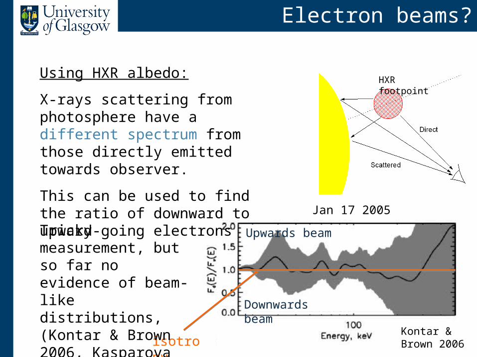
Electron beams?
Jan 17 2005
isotropy
Upwards beam
Downwards beam
Using HXR albedo:
X-rays scattering from photosphere have a different spectrum from those directly emitted towards observer.
This can be used to find the ratio of downward to upward-going electrons
HXR footpoint
Tricky measurement, but so far no evidence of beam-like distributions, (Kontar & Brown 2006, Kasparova et al 2007)
Kontar & Brown 2006
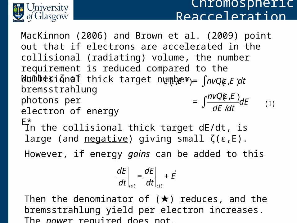
Chromospheric Reacceleration
MacKinnon (2006) and Brown et al. (2009) point out that if electrons are accelerated in the collisional (radiating) volume, the number requirement is reduced compared to the collisional thick target number.
€
ζ ε, E *( ) = nvQ ε,E( )∫ dt
=nvQ ε, E( )
dE /dt∫ dE
Number ζ of bremsstrahlung photons per electron of energy E*
In the collisional thick target dE/dt, is large (and negative) giving small ζ(ε,E).
However, if energy gains can be added to this
€
dE
dt tot
=dE
dt ctt
+ ˙ E
Then the denominator of (★) reduces, and the bremsstrahlung yield per electron increases. The power required does not.
(★)
Transport and acceleration
Acceleration of electrons in the chromosphere requires:
- Fast, non-dissipative transport of flare energy chomosphere- Chromospheric acceleration that is fast enough to overcome Coulomb collisional losses (heating)
A wave-based view:Following coronal reconnection, field reorganises, generating MHD disturbances (fast, slow, Alfvén).
Alfvén wave pulse travels rapidly along B, carrying a Poynting flux. It is the agent for flare energy transport to the chromosphere.
Flare-related wave energy transfer has been proposed by several authors (e.g. Emslie & Sturrock 1982, Melrose 1993, Haerendel 2006, Fletcher & Hudson 2008)
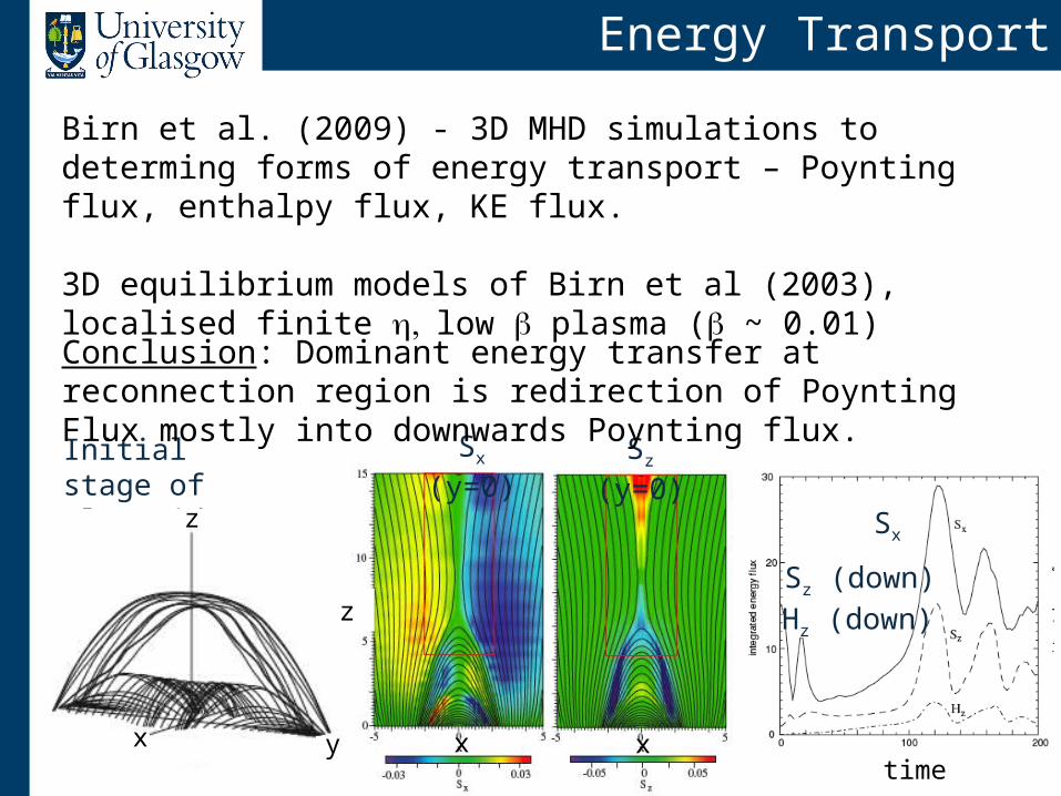
Energy Transport
Birn et al. (2009) - 3D MHD simulations to determing forms of energy transport – Poynting flux, enthalpy flux, KE flux.
3D equilibrium models of Birn et al (2003), localised finite low plasma ( ~ 0.01)
Initial stage of plasmoid ejection
x
z
y x x
z
Sx (y=0) Sz (y=0)
time
Sx
Sz (down) Hz (down)
Conclusion: Dominant energy transfer at reconnection region is redirection of Poynting Flux mostly into downwards Poynting flux.
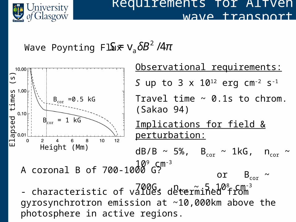
Requirements for Alfvén wave transport
Observational requirements:
S up to 3 x 10¹² erg cm-2 s-1
Travel time ~ 0.1s to chrom. (Sakao 94)
Implications for field & perturbation:
dB/B ~ 5%, Bcor ~ 1kG, ncor ~ 109 cm-3
or Bcor ~ 700G, ncor ~ 5.108 cm-3
Elap
sed
times
(s)
Bcor =0.5 kG
Bcor = 1 kG
Height (Mm)
€
S = va δB2 /4πWave Poynting Flux
A coronal B of 700-1000 G?
- characteristic of values determined from gyrosynchrotron emission at ~10,000km above the photosphere in active regions.
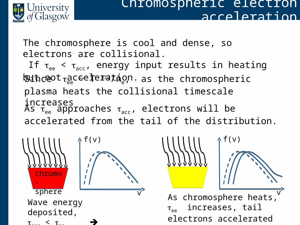
Chromospheric electron acceleration
The chromosphere is cool and dense, so electrons are collisional. If ee < acc, energy input results in heating but not acceleration.
Since ee ~ T 3/2/ne, as the chromospheric plasma heats the collisional timescale increases
As ee approaches acc, electrons will be accelerated from the tail of the distribution.
Wave energy deposited, acc < ee heating
As chromosphere heats, ee increases, tail electrons accelerated
chromo-sphere
v
f(v)
v
f(v)
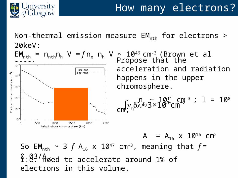
How many electrons?
Non-thermal emission measure EMnth for electrons > 20keV: EMnth = nnthnh V = f ne nh V ~ 1046 cm-3 (Brown et al 2009)
Propose that the acceleration and radiation happens in the upper chromosphere.
ne ~ 1011 cm-3 ; l = 108 cm;
A = A16 x 1016 cm2
€
nh∫ dl≈3×1020cm−2
So EMnth ~ 3 f A16 x 1047 cm-3, meaning that f = 0.03/A16
i.e. need to accelerate around 1% of electrons in this volume.

Chromospheric footpoint heating
In a Maxwellian, the fraction fχ above energy χ= E/kT is
Acceleration cannot take place at normal chromospheric temperatures and temperatures.
Evidence for impulsive phase footpoint heating to ~ 10MK; • SXT impulsive phase footpoints (Hudson et al 94 Mrozek & Tomczak 04)• EIS footpoint imaging spectroscopy (Milligan et al 2009, 2010)
fχ = 0.01 means χ= E/kT = 5.5 and thus E ~ 6 keV in a 10MK plasma. Mechanism must accelerate 6 keV electrons faster than they lose energy collisionally.
v
f(v)
fχ
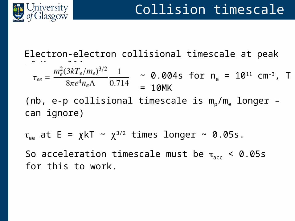
Collision timescale
Electron-electron collisional timescale at peak of Maxwellian
So acceleration timescale must be acc < 0.05s for this to work.
(nb, e-p collisional timescale is mp/me longer – can ignore)
ee at E = χkT ~ χ3/2 times longer ~ 0.05s.
~ 0.004s for ne = 1011 cm-3, T = 10MK
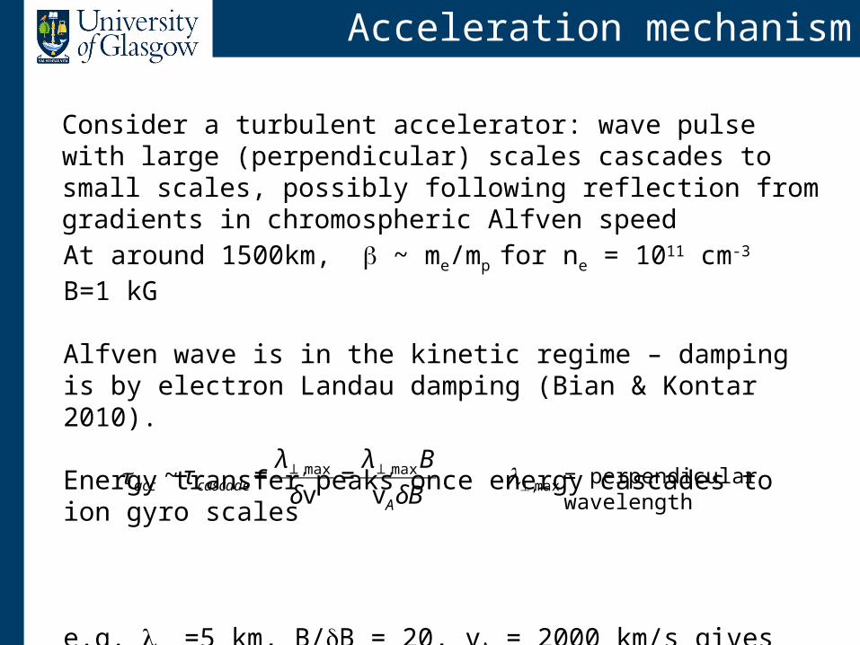
Acceleration mechanism
At around 1500km, ~ me/mp for ne = 1011 cm-3 B=1 kG
Alfven wave is in the kinetic regime – damping is by electron Landau damping (Bian & Kontar 2010).
Energy transfer peaks once energy cascades to ion gyro scales
e.g. max=5 km, B/B = 20, vA = 2000 km/s gives tacc ~ 0.05s
€
acc ~ τ cascade =λ⊥,max
δv=
λ⊥,maxB
vAδB
€
⊥,max = perpendicular wavelength
Consider a turbulent accelerator: wave pulse with large (perpendicular) scales cascades to small scales, possibly following reflection from gradients in chromospheric Alfven speed
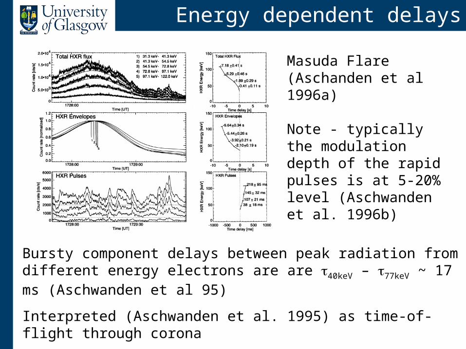
Energy dependent delays
Bursty component delays between peak radiation from different energy electrons are are 40keV – 77keV ~ 17 ms (Aschwanden et al 95)
Interpreted (Aschwanden et al. 1995) as time-of-flight through corona
Smooth compt delays: 50keV – 200keV = - 1 to -10 s (Aschwanden et al 1997)
Masuda Flare (Aschanden et al 1996a)
Note - typically the modulation depth of the rapid pulses is at 5-20% level (Aschwanden et al. 1996b)
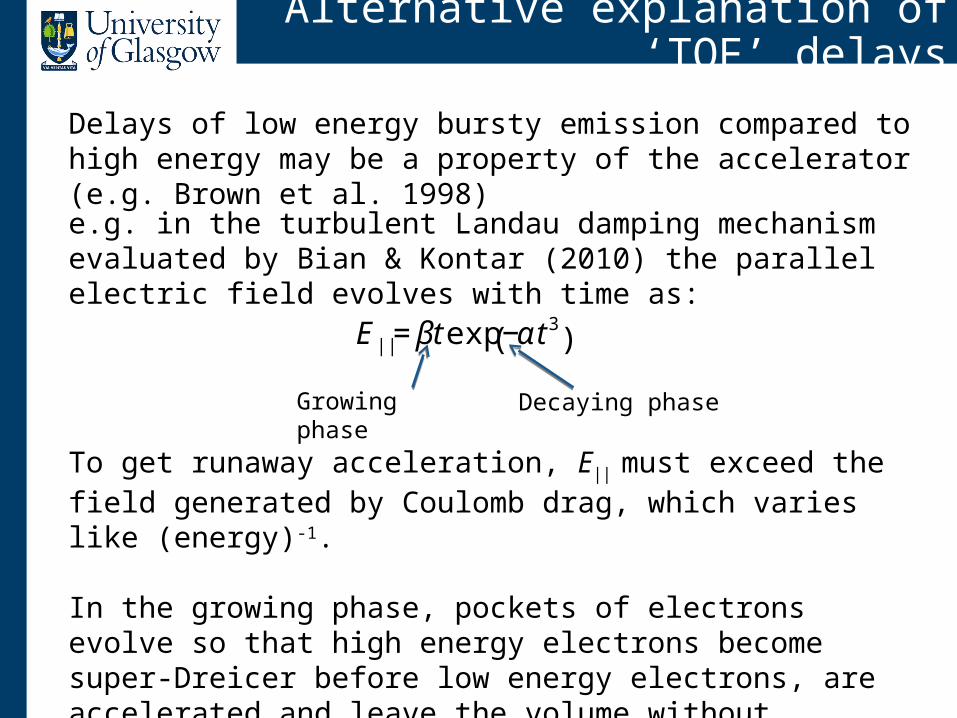
Alternative explanation of ‘TOF’ delays
Delays of low energy bursty emission compared to high energy may be a property of the accelerator (e.g. Brown et al. 1998)
To get runaway acceleration, E|| must exceed the field generated by Coulomb drag, which varies like (energy)-1.
In the growing phase, pockets of electrons evolve so that high energy electrons become super-Dreicer before low energy electrons, are accelerated and leave the volume without further collisions.
e.g. in the turbulent Landau damping mechanism evaluated by Bian & Kontar (2010) the parallel electric field evolves with time as:
€
E || = βt exp −αt 3( )
Growing phase Decaying phase
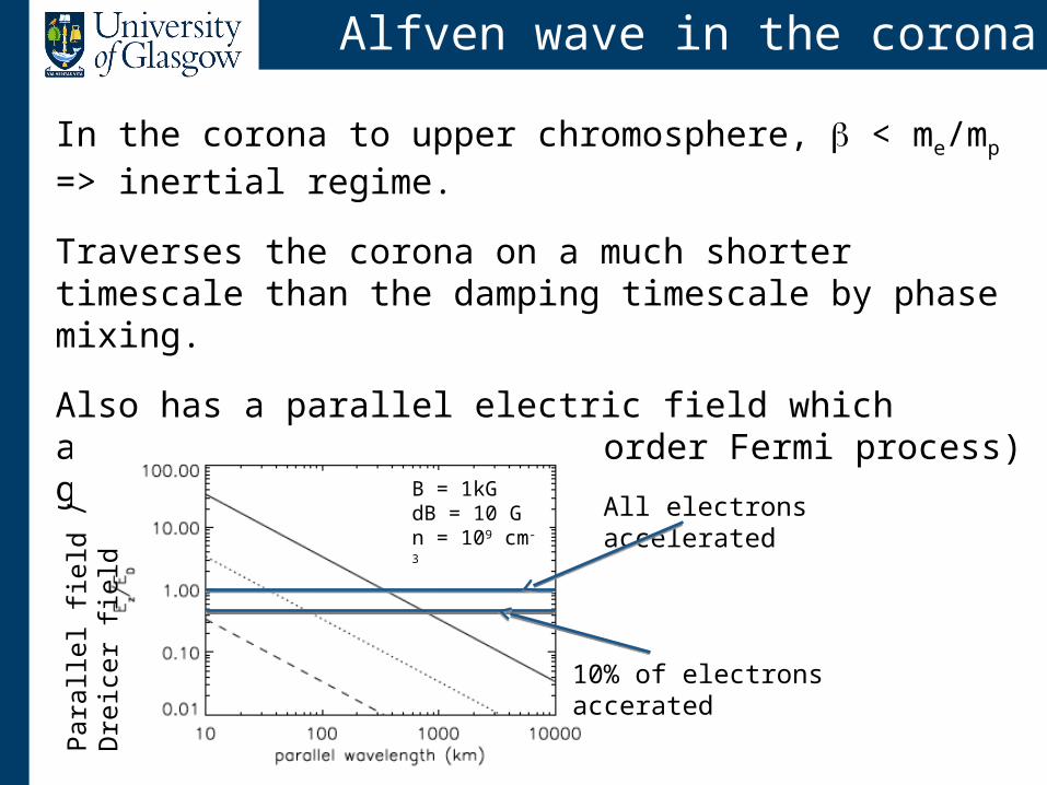
Alfven wave in the corona
In the corona to upper chromosphere, < me/mp => inertial regime.
Traverses the corona on a much shorter timescale than the damping timescale by phase mixing.
Also has a parallel electric field which accelerates electrons (1st order Fermi process) giving E = 2mvA
2
All electrons accelerated
10% of electrons accerated
Para
llel fi
eld
/ D
reic
er fi
eld
B = 1kGdB = 10 Gn = 109 cm-3

Alfven wave in lower chromosphere
As ionisation fraction drops in lower chromosphere, dissipation & direct heating by ion-neutral coupling might become important
Dissipation most effective in partially-ionised medium – e.g. at ~ 1000 km in Kasparova et al. (2009) model
Also need wave pulse ‘period’ ~ ion-neutral collision timescale.
0.01s
0.1s
Collision frequencies for VAL-C model (De Pontieu et al 2001)
Need to recalculate for flare models, and compare with typical wave periods – maybe L/vA = 0.1s
Conclusions
• With tightening observational constraints the coronal electron beam/collisional thick target model is increasingly challenged
• The number of HXR photons per electron can be increased if the electrons are accelerated in the volume where they collide and radiate (Mackinnon 2006)
• Brown et. al (2009) propose to reaccelerate a small number of coronal electrons in the chromosphere but do not explain how the energy required arrives there
• Fletcher & Hudson (2008) propose to transport energy to chromosphere with Alfvenic perturbations, and accelerate electrons in the Alfvenic turbulence generate there.
• Chromosphere must be first heated to ~10MK and then a non-thermal tail of about 1% pulled out.
• ‘TOF’ delays can be explained as a property of a turbulent accelerator

![Jack Canfield TTT November 2009[1] · 2016-05-04 · Guest Expert Tele‐Training November 18, 2009 FEATURING: Jack Canfield Question & Answer Session The Canfield Training Group,](https://img.pdfslide.us/doc/110x75/5eba525c1a4e563c2a1cdee2/jack-canfield-ttt-november-20091-2016-05-04-guest-expert-teleatraining-november.jpg)