Embed Size (px)
Citation preview
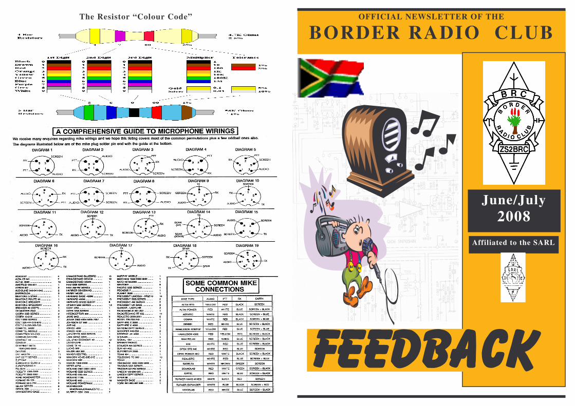
The Resistor “Colour Code” OFFICIAL NEWSLETTER OF THE
BORDER RADIO CLUB
June/July 2008
Affiliated to the SARL
For the Hams that have Packet in their shack. My “ UFO Interest Group News” is on our local BBS Packet station. This Interest Group I formed over one year ago and it is sent World Wide. I receive reply’s from many different countries from fellow Ham’s that follow the UFO phenomena. I put out this type of Bulletin on a weekly basis and some times more frequent, on to ZS0ELD BBS. There are many , News, Technical , discussion forums and, infor-mation to be had for Free on the Bulletin Board Service. The Local BBS is run by Ivan ZS2ILN. Please send me your sightings or UFO stories. (If requested your Call sign will not be published). ZS2ABF
.Nico ZS2NC Fiddling inside his HF Radio, during one of our Lighthouse weekends. I wonder if it ever worked again ?. May be that’s why we don’t hear him on the air ! Hi..
We wish to apologize but the repeater has gone Dead again !
ZS2PRT !
Shack of the month - ZS2NB
Neil, Now that’s what I call a good Boot Sale !!!
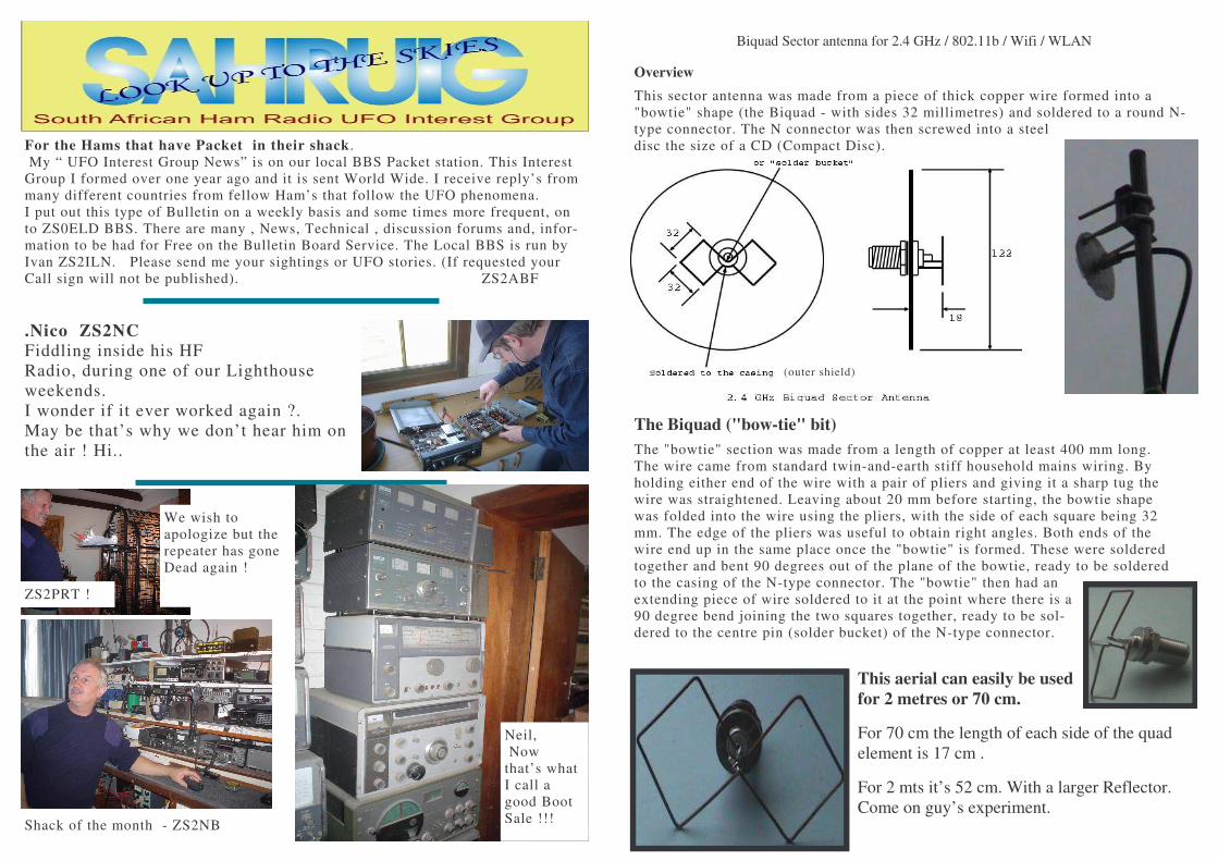
Biquad Sector antenna for 2.4 GHz / 802.11b / Wifi / WLAN
Overview This sector antenna was made from a piece of thick copper wire formed into a "bowtie" shape (the Biquad - with sides 32 millimetres) and soldered to a round N-type connector. The N connector was then screwed into a steel disc the size of a CD (Compact Disc).
The Biquad ("bow-tie" bit) The "bowtie" section was made from a length of copper at least 400 mm long. The wire came from standard twin-and-earth stiff household mains wiring. By holding either end of the wire with a pair of pliers and giving it a sharp tug the wire was straightened. Leaving about 20 mm before starting, the bowtie shape was folded into the wire using the pliers, with the side of each square being 32 mm. The edge of the pliers was useful to obtain right angles. Both ends of the wire end up in the same place once the "bowtie" is formed. These were soldered together and bent 90 degrees out of the plane of the bowtie, ready to be soldered to the casing of the N-type connector. The "bowtie" then had an extending piece of wire soldered to it at the point where there is a 90 degree bend joining the two squares together, ready to be sol-dered to the centre pin (solder bucket) of the N-type connector.
This aerial can easily be used for 2 metres or 70 cm.
For 70 cm the length of each side of the quad element is 17 cm .
For 2 mts it’s 52 cm. With a larger Reflector. Come on guy’s experiment.
(outer shield)
From the
����������� ���
Peter ZS2ABF has taken over the Editorship and, compilation of your Feed-back magazine. Tony has had to bow out due to pres-sure of work at the salt mine. We thank you Tony for get-ting our magazine up and
running again and taking it this far. The committee hope you like it in it’s Email colour format. It looks a lot better that way. If you insist on a printed, copy then it will only be in Black and White. Now the crunch line. @#@!%#$* If no material is received for publishing the following applies: “nothing in nothing out”. Therefore in order to continue with our magazine please supply a r t i c l e s o r p h o t o g r a p h s t o [email protected] Below is a picture of my shack, make sure your articles etc arrive there.
A word from
T��������� ����� ����������� ����� ����������� ����� ����������� ����� ������
�
Sorry I don’t talk a lot but I eat a lot. Again and again. Peter has just said my piece and I can’t talk with my mouth full. Or type with my hands full.
ZS2NB & ZS2ILN in their new BRC uniforms !!!.(SARL AGM Bloem)
The 4 prize winners at the P.E. TRA Lectures June 2008.
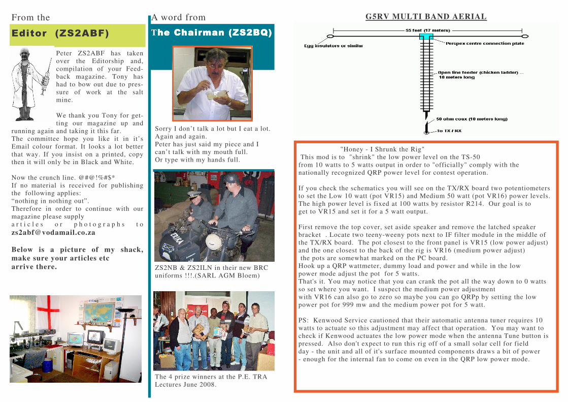
G5RV MULTI BAND AERIAL
"Honey - I Shrunk the Rig" This mod is to "shrink" the low power level on the TS-50 from 10 watts to 5 watts output in order to "officially" comply with the nationally recognized QRP power level for contest operation. If you check the schematics you will see on the TX/RX board two potentiometers to set the Low 10 watt (pot VR15) and Medium 50 watt (pot VR16) power levels. The high power level is fixed at 100 watts by resistor R214. Our goal is to get to VR15 and set it for a 5 watt output. First remove the top cover, set aside speaker and remove the latched speaker bracket . Locate two teeny-weeny pots next to IF filter module in the middle of the TX/RX board. The pot closest to the front panel is VR15 (low power adjust) and the one closest to the back of the rig is VR16 (medium power adjust) the pots are somewhat marked on the PC board. Hook up a QRP wattmeter, dummy load and power and while in the low power mode adjust the pot for 5 watts. That's it. You may notice that you can crank the pot all the way down to 0 watts so set where you want. I suspect the medium power adjustment with VR16 can also go to zero so maybe you can go QRPp by setting the low power pot for 999 mw and the medium power pot for 5 watt. PS: Kenwood Service cautioned that their automatic antenna tuner requires 10 watts to actuate so this adjustment may affect that operation. You may want to check if Kenwood actuates the low power mode when the antenna Tune button is pressed. Also don't expect to run this rig off of a small solar cell for field day - the unit and all of it's surface mounted components draws a bit of power - enough for the internal fan to come on even in the QRP low power mode.
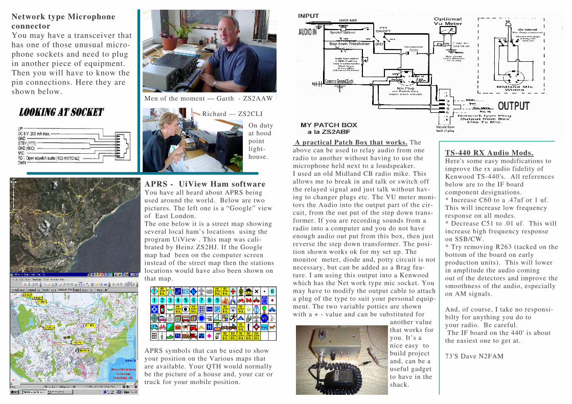
Network type Microphone connector You may have a transceiver that has one of those unusual micro-phone sockets and need to plug in another piece of equipment. Then you will have to know the pin connections. Here they are shown below.
APRS - UiView Ham software You have all heard about APRS being used around the world. Below are two pictures. The left one is a “Google” view of East London. The one below it is a street map showing several local ham’s locations using the program UiView . This map was cali-brated by Heinz ZS2HJ. If the Google map had been on the computer screen instead of the street map then the stations locations would have also been shown on that map.
APRS symbols that can be used to show your position on the Various maps that are available. Your QTH would normally be the picture of a house and, your car or truck for your mobile position.
Men of the moment — Garth - ZS2AAW
Richard — ZS2CLI
On duty at hood point light-house.
A practical Patch Box that works. The above can be used to relay audio from one radio to another without having to use the microphone held next to a loudspeaker. I used an old Midland CB radio mike. This allows me to break in and talk or switch off the relayed signal and just talk without hav-ing to changer plugs etc. The VU meter moni-tors the Audio into the output part of the cir-cuit, from the out put of the step down trans-former. If you are recording sounds from a radio into a computer and you do not have enough audio out put from this box, then just reverse the step down transformer. The posi-tion shown works ok for my set up. The monitor meter, diode and, potty circuit is not necessary, but can be added as a Brag fea-ture. I am using this output into a Kenwood which has the Net work type mic socket. You may have to modify the output cable to attach a plug of the type to suit your personal equip-ment. The two variable potties are shown with a + - value and can be substituted for
another value that works for you. It’s a nice easy to build project and, can be a useful gadget to have in the shack.
TS-440 RX Audio Mods. Here's some easy modifications to improve the rx audio fidelity of Kenwood TS-440's. All references below are to the IF board component designations. * Increase C60 to a .47uf or 1 uf. This will increase low frequency response on all modes. * Decrease C51 to .01 uf. This will increase high frequency response on SSB/CW. * Try removing R263 (tacked on the bottom of the board on early production units). This will lower in amplitude the audio coming out of the detectors and improve the smoothness of the audio, especially on AM signals. And, of course, I take no responsi-bilty for anything you do to your radio. Be careful. The IF board on the 440' is about the easiest one to get at. 73'S Dave N2FAM