Embed Size (px)
Citation preview
CS162Operating Systems andSystems Programming
Lecture 16
General I/O
October 24th, 2016Prof. Anthony D. Joseph
http://cs162.eecs.Berkeley.edu
Lec 16.210/24/16 Joseph CS162 ©UCB Fall 2016
The Requirements of I/O
• So far in this course:– We have learned how to manage CPU and memory
• What about I/O?– Without I/O, computers are useless (disembodied brains?)– But… thousands of devices, each slightly different
» How can we standardize the interfaces to these devices?– Devices unreliable: media failures and transmission errors
» How can we make them reliable???– Devices unpredictable and/or slow
» How can we manage them if we don’t know what they will do or how they will perform?
Lec 16.310/24/16 Joseph CS162 ©UCB Fall 2016
OS Basics: I/O
storage
Processor
OS Hardware Virtualization
Hardware
Software
Memory
Networks
DisplaysInputs
ProcessesAddress Spaces
Files
ISA
WindowsSockets
OS
Threads
Protection Boundary
Ctrlr
Lec 16.410/24/16 Joseph CS162 ©UCB Fall 2016
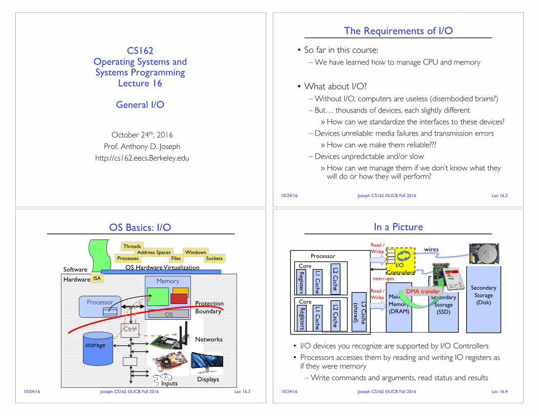
In a Picture
• I/O devices you recognize are supported by I/O Controllers• Processors accesses them by reading and writing IO registers as
if they were memory– Write commands and arguments, read status and results
Core
Core
SecondaryStorage (Disk)
Processor
MainMemory(DRAM)
SecondaryStorage (SSD)
I/O Controllers
Read / Write
Read / Write wires
interrupts
DMA transfer

Lec 16.510/24/16 Joseph CS162 ©UCB Fall 2016
Operational Parameters for I/O
• Data granularity: Byte vs. Block– Some devices provide single byte at a time (e.g., keyboard)– Others provide whole blocks (e.g., disks, networks, etc.)
• Access pattern: Sequential vs. Random– Some devices must be accessed sequentially (e.g., tape)– Others can be accessed “randomly” (e.g., disk, cd, etc.)
» Fixed overhead to start transfers– Some devices require continual monitoring– Others generate interrupts when they need service
• Transfer Mechanism: Programmed IO and DMA
Lec 16.610/24/16 Joseph CS162 ©UCB Fall 2016
Kernel Device StructureThe System Call Interface
ProcessManagement
MemoryManagement
FilesystemsDeviceControl
Networking
ArchitectureDependent
Code
MemoryManager
DeviceControl
NetworkSubsystem
File System Types
BlockDevices
IF drivers
Concurrency,multitasking
Virtualmemory
Files and dirs:the VFS
TTYs anddevice access Connectivity
Lec 16.710/24/16 Joseph CS162 ©UCB Fall 2016
The Goal of the I/O Subsystem
• Provide Uniform Interfaces, Despite Wide Range of Different Devices
– This code works on many different devices:FILE%fd =%fopen("/dev/something", "rw");for%(int i =%0;%i <%10;%i++)%{
fprintf(fd,%"Count%%d\n",%i);}close(fd);
– Why? Because code that controls devices (“device driver”) implements standard interface
• We will try to get a flavor for what is involved in actually controlling devices in rest of lecture
– Can only scratch surface!
Lec 16.810/24/16 Joseph CS162 ©UCB Fall 2016
Want Standard Interfaces to Devices• Block Devices: e.g. disk drives, tape drives, DVD-ROM
– Access blocks of data– Commands include open(), read(), write(), seek()– Raw I/O or file-system access– Memory-mapped file access possible
• Character Devices: e.g. keyboards, mice, serial ports, some USB devices
– Single characters at a time– Commands include get(), put()– Libraries layered on top allow line editing
• Network Devices: e.g. Ethernet, Wireless, Bluetooth– Different enough from block/character to have own interface– Unix and Windows include socket interface
» Separates network protocol from network operation» Includes select()%functionality
– Usage: pipes, FIFOs, streams, queues, mailboxes
Lec 16.910/24/16 Joseph CS162 ©UCB Fall 2016
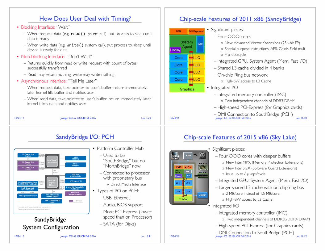
How Does User Deal with Timing?• Blocking Interface: “Wait”
– When request data (e.g. read() system call), put process to sleep until data is ready
– When write data (e.g. write() system call), put process to sleep until device is ready for data
• Non-blocking Interface: “Don’t Wait”– Returns quickly from read or write request with count of bytes
successfully transferred– Read may return nothing, write may write nothing
• Asynchronous Interface: “Tell Me Later”– When request data, take pointer to user’s buffer, return immediately;
later kernel fills buffer and notifies user– When send data, take pointer to user’s buffer, return immediately; later
kernel takes data and notifies user
Lec 16.1010/24/16 Joseph CS162 ©UCB Fall 2016
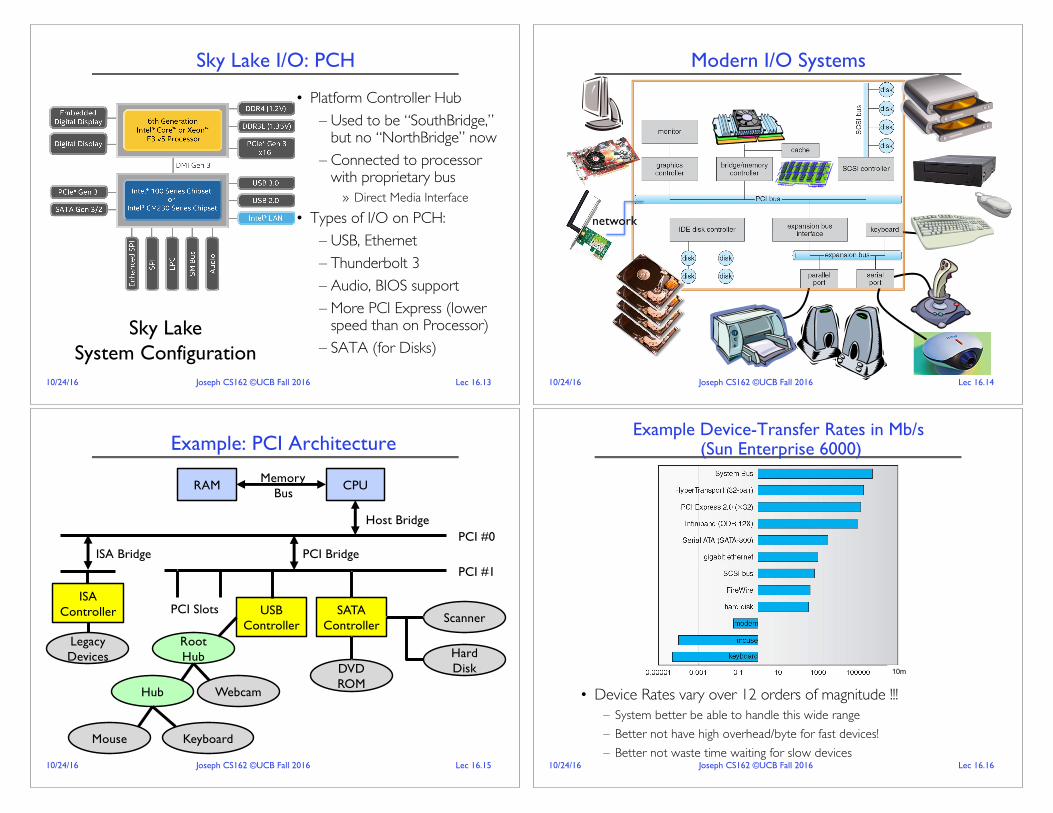
Chip-scale Features of 2011 x86 (SandyBridge)
• Significant pieces:– Four OOO cores
» New Advanced Vector eXtensions (256-bit FP)» Special purpose instructions: AES, Galois-Field mult» 4 µ-ops/cycle
– Integrated GPU, System Agent (Mem, Fast I/O)– Shared L3 cache divided in 4 banks– On-chip Ring bus network
» High-BW access to L3 Cache• Integrated I/O
– Integrated memory controller (IMC)» Two independent channels of DDR3 DRAM
– High-speed PCI-Express (for Graphics cards)– DMI Connection to SouthBridge (PCH)
Lec 16.1110/24/16 Joseph CS162 ©UCB Fall 2016
SandyBridge I/O: PCH
• Platform Controller Hub– Used to be
“SouthBridge,” but no “NorthBridge” now
– Connected to processor with proprietary bus
» Direct Media Interface• Types of I/O on PCH:
– USB, Ethernet– Audio, BIOS support– More PCI Express (lower
speed than on Processor)– SATA (for Disks)
SandyBridgeSystem Configuration
Lec 16.1210/24/16 Joseph CS162 ©UCB Fall 2016
Chip-scale Features of 2015 x86 (Sky Lake)
• Significant pieces:– Four OOO cores with deeper buffers
» New Intel MPX (Memory Protection Extensions)» New Intel SGX (Software Guard Extensions)» Issue up to 6 µ-ops/cycle
– Integrated GPU, System Agent (Mem, Fast I/O)– Larger shared L3 cache with on-chip ring bus
» 2 MB/core instead of 1.5 MB/core» High-BW access to L3 Cache
• Integrated I/O– Integrated memory controller (IMC)
» Two independent channels of DDR3L/DDR4 DRAM– High-speed PCI-Express (for Graphics cards)– DMI Connection to SouthBridge (PCH)
Lec 16.1310/24/16 Joseph CS162 ©UCB Fall 2016
Sky Lake I/O: PCH
• Platform Controller Hub– Used to be “SouthBridge,”
but no “NorthBridge” now– Connected to processor
with proprietary bus» Direct Media Interface
• Types of I/O on PCH:– USB, Ethernet– Thunderbolt 3– Audio, BIOS support– More PCI Express (lower
speed than on Processor)– SATA (for Disks)
Sky LakeSystem Configuration
Lec 16.1410/24/16 Joseph CS162 ©UCB Fall 2016
Modern I/O Systems
network
Lec 16.1510/24/16 Joseph CS162 ©UCB Fall 2016
Example: PCI Architecture
CPURAM MemoryBus
USBController
SATAController
Scanner
Hard DiskDVD
ROM
Root Hub
Hub Webcam
Mouse Keyboard
PCI #1
PCI #0PCI Bridge
PCI Slots
Host Bridge
ISA Bridge
ISAController
LegacyDevices
Lec 16.1610/24/16 Joseph CS162 ©UCB Fall 2016
Example Device-Transfer Rates in Mb/s(Sun Enterprise 6000)
• Device Rates vary over 12 orders of magnitude !!!– System better be able to handle this wide range– Better not have high overhead/byte for fast devices!– Better not waste time waiting for slow devices
10m

Lec 16.1710/24/16 Joseph CS162 ©UCB Fall 2016
Administrivia
• Midterm 2 TOMORROW on Tue 10/25 6:30-8PM– All topics up to and including Lecture 15
» Focus will be on Lectures 9 – 15 and associated readings» Projects 1 & 2, Homework 0 – 2
– Closed book with 2 pages of hand-written notes both sides– Room assignments by last name:
» 10 Evans (A – K), 1 LeConte (L – S), 60 Evans (T – Z)
Lec 16.1810/24/16 Joseph CS162 ©UCB Fall 2016
Recall: Internet of Things Botnets
• Hackers take over Internet of Things devices:– Mirai (233,000 infected IoT devices) and Bashlight (963,000)
• Responsible for 620 Gb/s attack against Brian Krebs’ website– Largest Distributed Denial of Service attack ever!!
• Followed a few days later by 1.1 Tb/s attack against French cloud and web hosting provider
– Largest Distributed Denial of Service attack ever!!– Roughly 145,000 Internet attached cameras
• IoT devices compromised using default and hardcoded passwords
Lec 16.1910/24/16 Joseph CS162 ©UCB Fall 2016
Friday Oct 21 2016 IoT Attack
• IoT attack against DNS servers run by Dyn Corp– 3 attack waves: 7:00 am ET, 12:00pm ET, (third attack blocked)– Mirai botnet spoofed (faked) 10Ms of IP addr (maybe 50k hosts)
» TCP SYN floods to DNS servers port 53, also DNS prepend attack– Affected Twitter, SoundCloud, Spotify, Reddit, Amazon, Netflix,
PayPal, Airbnb, Reddit, Etsy, New York Times, 10k+ more sites … Lec 16.2010/24/16 Joseph CS162 ©UCB Fall 2016
Solutions?• Legislative?
– Criminal charges – already exists but how to identify who is responsible?– Mandatory recall – how to identify white label devices? how to enforce?
» Hangzhou Xiongmai Tech hardcoded passwords into camera boards (announced recall? on Monday 10/24)
– Fines – who should be fined?– ISPs block users – huge customer support nightmare…
• Technical?– Blocking IP addresses – attack used spoofed IP addresses– Create a “good” worm to patch vulnerable devices – how would users
gain access to their devices? Some devices have hardcoded passwords
• UL Label?– Develop industry standards and best practices– Mandate thorough security testing of IoT devices

Lec 16.2110/24/16 Joseph CS162 ©UCB Fall 2016
BREAK
Lec 16.2210/24/16 Joseph CS162 ©UCB Fall 2016
• CPU interacts with a Controller– Contains a set of registers that
can be read and written– May contain memory for request
queues or bit-mapped images • Regardless of the complexity of the connections and buses, processor
accesses registers in two ways: – I/O instructions: in/out instructions
» Example from the Intel architecture: out%0x21,AL– Memory mapped I/O: load/store instructions
» Registers/memory appear in physical address space» I/O accomplished with load and store instructions
How does the processor actually talk to the device?
DeviceController
readwritecontrolstatus
AddressableMemoryand/orQueuesRegisters
(port 0x20)
HardwareController
Memory MappedRegion: 0x8f008020
BusInterface
Address +Data
Interrupt Request
Processor Memory Bus
CPU
RegularMemory
InterruptController
BusAdaptor
BusAdaptor
Other Devicesor Buses
Lec 16.2310/24/16 Joseph CS162 ©UCB Fall 2016
Example: Memory-Mapped Display Controller
• Memory-Mapped:– Hardware maps control registers and display
memory into physical address space» Addresses set by HW jumpers or at boot time
– Simply writing to display memory (also called the “frame buffer”) changes image on screen
» Addr: 0x8000F000%— 0x8000FFFF
– Writing graphics description to cmd queue» Say enter a set of triangles describing some scene» Addr: 0x80010000%— 0x8001FFFF
– Writing to the command register may cause on-board graphics hardware to do something
» Say render the above scene» Addr: 0x0007F004
• Can protect with address translation
DisplayMemory
0x8000F000
0x80010000
Physical AddressSpace
Status0x0007F000Command0x0007F004
GraphicsCommandQueue
0x80020000
Lec 16.2410/24/16 Joseph CS162 ©UCB Fall 2016
• Programmed I/O:– Each byte transferred via processor in/out or load/store– Pro: Simple hardware, easy to program– Con: Consumes processor cycles proportional to data size
• Direct Memory Access:– Give controller access to memory bus– Ask it to transfer
data blocks to/from memory directly
• Sample interaction with DMA controller(from OSC book):
addrlen
Transferring Data To/From Controller

Lec 16.2510/24/16 Joseph CS162 ©UCB Fall 2016
I/O Device Notifying the OS
• The OS needs to know when:– The I/O device has completed an operation– The I/O operation has encountered an error
• I/O Interrupt:– Device generates an interrupt whenever it needs service– Pro: handles unpredictable events well– Con: interrupts relatively high overhead
• Polling:– OS periodically checks a device-specific status register
» I/O device puts completion information in status register– Pro: low overhead– Con: may waste many cycles on polling if infrequent or unpredictable I/O
operations• Actual devices combine both polling and interrupts
– For instance – High-bandwidth network adapter: » Interrupt for first incoming packet» Poll for following packets until hardware queues are empty
Lec 16.2610/24/16 Joseph CS162 ©UCB Fall 2016
Device Drivers• Device Driver: Device-specific code in the kernel that interacts
directly with the device hardware– Supports a standard, internal interface– Same kernel I/O system can interact easily with different device drivers– Special device-specific configuration supported with the ioctl()
system call
• Device Drivers typically divided into two pieces:– Top half: accessed in call path from system calls
» implements a set of standard, cross-device calls like open(), close(),read(), write(), ioctl(), strategy()
» This is the kernel’s interface to the device driver» Top half will start I/O to device, may put thread to sleep until finished
– Bottom half: run as interrupt routine» Gets input or transfers next block of output» May wake sleeping threads if I/O now complete
Lec 16.2710/24/16 Joseph CS162 ©UCB Fall 2016
Life Cycle of An I/O Request
Device DriverTop Half
Device DriverBottom Half
DeviceHardware
Kernel I/OSubsystem
UserProgram
Lec 16.2810/24/16 Joseph CS162 ©UCB Fall 2016
Basic Performance Concepts
• Response Time or Latency: Time to perform an operation(s)
• Bandwidth or Throughput: Rate at which operations are performed (op/s)– Files: MB/s, Networks: Mb/s, Arithmetic: GFLOP/s
• Start up or “Overhead”: time to initiate an operation
• Most I/O operations are roughly linear in n bytes– Latency(n) = Overhead + n/Bandwidth

Lec 16.2910/24/16 Joseph CS162 ©UCB Fall 2016
Example (Fast Network)• Consider a 1 Gb/s link (B = 125 MB/s)
– With a startup cost S = 1 ms
• Theorem: half-power point occurs at n=S*B:– n = 1 ms x 125 MB/s = 125,000 bytes
Lec 16.3010/24/16 Joseph CS162 ©UCB Fall 2016
Example: at 10 ms startup (like Disk)
0""
5""
10""
15""
20""
25""
30""
35""
40""
45""
50""
0""
2,000""
4,000""
6,000""
8,000""
10,000""
12,000""
14,000""
16,000""
18,000""
0"" 50,000""100,000""150,000""200,000""250,000""300,000""350,000""400,000""450,000""500,000""
Band
width)(m
B/s))
Latency)(us))
Length)(b))
Performance)of)gbps)link)with)10)ms)startup)
n = 1,250,000 bytes!
Lec 16.3110/24/16 Joseph CS162 ©UCB Fall 2016
What Determines Peak BW for I/O ?
• Bus Speed– PCI-X: 1064 MB/s = 133 MHz x 64 bit (per lane)– ULTRA WIDE SCSI: 40 MB/s– Serial Attached SCSI & Serial ATA & IEEE 1394 (firewire): 1.6 Gb/s
full duplex (200 MB/s)– USB 3.0 – 5 Gb/s– Thunderbolt 3 – 40 Gb/s
• Device Transfer Bandwidth– Rotational speed of disk– Write / Read rate of NAND flash– Signaling rate of network link
• Whatever is the bottleneck in the path…Lec 16.3210/24/16 Joseph CS162 ©UCB Fall 2016
BREAK

Lec 16.3310/24/16 Joseph CS162 ©UCB Fall 2016
Storage Devices
• Magnetic disks– Storage that rarely becomes corrupted– Large capacity at low cost– Block level random access (except for SMR – later!)– Slow performance for random access– Better performance for streaming access
• Flash memory– Storage that rarely becomes corrupted– Capacity at intermediate cost (50x disk ???)– Block level random access– Good performance for reads; worse for random writes– Erasure requirement in large blocks– Wear patterns issue
Lec 16.3410/24/16 Joseph CS162 ©UCB Fall 2016
Are We in an Inflection Point?
Lec 16.3510/24/16 Joseph CS162 ©UCB Fall 2016
Hard Disk Drives (HDDs)
IBM/Hitachi Microdrive
Western Digital Drivehttp://www.storagereview.com/guide/
Read/Write HeadSide View
IBM Personal Computer/AT (1986)30 MB hard disk - $500 30-40ms seek time0.7-1 MB/s (est.)
Lec 16.3610/24/16 Joseph CS162 ©UCB Fall 2016
The Amazing Magnetic Disk
Track
Sector
Head Arm
Arm Assembly
Platter
Surface
Surface
Motor Motor
Spindle
• Unit of Transfer: Sector– Ring of sectors form a track– Stack of tracks form a cylinder– Heads position on cylinders
• Disk Tracks ~ 1µm (micron) wide
– Wavelength of light is ~ 0.5µm– Resolution of human eye: 50µm– 100K on a typical 2.5” disk
• Separated by unused guard regions– Reduces likelihood neighboring
tracks are corrupted during writes (still a small non-zero chance)

Lec 16.3710/24/16 Joseph CS162 ©UCB Fall 2016
The Amazing Magnetic Disk
Track
Sector
Head Arm
Arm Assembly
Platter
Surface
Surface
Motor Motor
Spindle
• Track length varies across disk– Outside: More sectors per track,
higher bandwidth– Disk is organized into regions of
tracks with same # of sectors/track
– Only outer half of radius is used» Most of the disk area in the
outer regions of the disk
Lec 16.3810/24/16 Joseph CS162 ©UCB Fall 2016
Shingled Magnetic Recording (SMR)
• Overlapping tracks yields greater density, capacity• Restrictions on writing, complex DSP for reading• Examples: Seagate (8TB), Hitachi (10TB)
Lec 16.3910/24/16 Joseph CS162 ©UCB Fall 2016
Magnetic Disk Characteristic
• Cylinder: all the tracks under the head at a given point on all surfaces
• Read/write: three-stage process:– Seek time: position head/arm over proper track (into proper cylinder)– Rotational latency: wait for desired sector to rotate under R/W head– Transfer time: transfer a block of bits (sector) under the R/W head
• Disk Latency = Queuing Time + Controller time +Seek Time + Rotation Time + Xfer Time
• Highest Bandwidth: – Transfer large group of blocks sequentially from one track
SectorTrack
CylinderHead
Platter
SoftwareQueue(Device Driver)
Hardw
areC
ontroller
Media Time(Seek+Rot+Xfer)
Request
Result
Lec 16.4010/24/16 Joseph CS162 ©UCB Fall 2016
Typical Numbers for Magnetic Disk
Parameter Info / RangeSpace/Density Space: 8TB (Seagate), 10TB (Hitachi) in 3½ inch form factor!
Areal Density: ≥ 1Terabit/square inch! (SMR, Helium, …)Average seek time Typically 5-10 milliseconds.
Depending on reference locality, actual cost may be 25-33% of this number.
Average rotational latency
Most laptop/desktop disks rotate at 3600-7200 RPM (16-8 ms/rotation). Server disks up to 15,000 RPM.Average latency is halfway around disk so 8-4 milliseconds
Controller time Depends on controller hardwareTransfer time Typically 50 to 100 MB/s. Depends on:
• Transfer size (usually a sector): 512B – 1KB per sector• Rotation speed: 3600 RPM to 15000 RPM• Recording density: bits per inch on a track• Diameter : ranges from 1 in to 5.25 in
Cost Drops by a factor of two every 1.5 years (or even faster).$0.019/GB in 2016

Lec 16.4110/24/16 Joseph CS162 ©UCB Fall 2016
Hard Drive Prices over Time
Lec 16.4210/24/16 Joseph CS162 ©UCB Fall 2016
Disk Performance Example• Assumptions:
– Ignoring queuing and controller times for now– Avg seek time of 5ms, – 7200RPM ! Time for rotation: 60000(ms/minute)/7200(rev/min) ~= 8ms– Transfer rate of 4MByte/s, sector size of 1 Kbyte !
1024 bytes/4×106 (bytes/s) = 256 × 10-6 sec " .26 ms• Read sector from random place on disk:
– Seek (5ms) + Rot. Delay (4ms) + Transfer (0.26ms)– Approx 10ms to fetch/put data: 100 KByte/sec
• Read sector from random place in same cylinder:– Rot. Delay (4ms) + Transfer (0.26ms)– Approx 5ms to fetch/put data: 200 KByte/sec
• Read next sector on same track:– Transfer (0.26ms): 4 MByte/sec
• Key to using disk effectively (especially for file systems) is to minimize seek and rotational delays
Lec 16.4310/24/16 Joseph CS162 ©UCB Fall 2016
(Lots of) Intelligence in the Controller• Sectors contain sophisticated error correcting codes
– Disk head magnet has a field wider than track– Hide corruptions due to neighboring track writes
• Sector sparing– Remap bad sectors transparently to spare sectors on the same surface
• Slip sparing– Remap all sectors (when there is a bad sector) to preserve sequential
behavior
• Track skewing– Sector numbers offset from one track to the next, to allow for disk
head movement for sequential ops
• …Lec 16.4410/24/16 Joseph CS162 ©UCB Fall 2016
Summary• I/O Devices Types:
– Many different speeds (0.1 bytes/sec to GBytes/sec)– Different Access Patterns:
» Block Devices, Character Devices, Network Devices– Different Access Timing:
» Blocking, Non-blocking, Asynchronous• I/O Controllers: Hardware that controls actual device
– Processor Accesses through I/O instructions, load/store to special physical memory
• Notification mechanisms– Interrupts– Polling: Report results through status register that processor looks at
periodically • Device drivers interface to I/O devices
– Provide clean Read/Write interface to OS above– Manipulate devices through PIO, DMA & interrupt handling– Three types: block, character, and network

Lec 16.4510/24/16 Joseph CS162 ©UCB Fall 2016
Second-Chance List Algorithm (VAX/VMS)
• Split memory in two: Active list (RW), SC list (Invalid)• Access pages in Active list at full speed• Otherwise, Page Fault
– Always move overflow page from end of Active list to front of Second-chance list (SC) and mark invalid
– Desired Page On SC List: move to front of Active list, mark RW– Not on SC list: page in to front of Active list, mark RW; page out LRU
victim at end of SC list
DirectlyMapped Pages
Marked: RWList: FIFO
Second Chance List
Marked: InvalidList: LRU
LRU victim
Page-inFrom disk
NewActivePages
New SCVictims
Lec 16.4610/24/16 Joseph CS162 ©UCB Fall 2016
Linux Memory Details?• Memory management in Linux considerably more complex that the
previous indications• Memory Zones: physical memory categories
– ZONE_DMA: < 16MB memory, DMAable on ISA bus– ZONE_NORMAL: 16MB ! 896MB (mapped at 0xC0000000)– ZONE_HIGHMEM: Everything else (> 896MB)
• Each zone has 1 freelist, 2 LRU lists (Active/Inactive)• Many different types of allocation
– SLAB allocators, per-page allocators, mapped/unmapped• Many different types of allocated memory:
– Anonymous memory (not backed by a file, heap/stack)– Mapped memory (backed by a file)
• Allocation priorities– Is blocking allowed/etc
Lec 16.4710/24/16 Joseph CS162 ©UCB Fall 2016
Recall: Linux Virtual memory map
KernelAddresses
EmptySpace
UserAddresses
UserAddresses
KernelAddresses
0x00000000
0xC0000000
0xFFFFFFFF
0x0000000000000000
0x00007FFFFFFFFFFF
0xFFFF800000000000
0xFFFFFFFFFFFFFFFF
3GB
Tota
l
128T
iB
1GB
128T
iB
896MBPhysical 64 TiB
Physical
32-Bit Virtual Address Space 64-Bit Virtual Address Space
“Canonical Hole”
Lec 16.4810/24/16 Joseph CS162 ©UCB Fall 2016
Virtual Map (Details)• Kernel memory not generally visible to user
– Exception: special VDSO (virtual dynamically linked shared objects) facility that maps kernel code into user space to aid in system calls (and to provide certain actual system calls such as gettimeofday()
• Every physical page described by a “page” structure– Collected together in lower physical memory– Can be accessed in kernel virtual space– Linked together in various “LRU” lists
• For 32-bit virtual memory architectures:– When physical memory < 896MB
» All physical memory mapped at 0xC0000000– When physical memory >= 896MB
» Not all physical memory mapped in kernel space all the time» Can be temporarily mapped with addresses > 0xCC000000
• For 64-bit virtual memory architectures:– All physical memory mapped above 0xFFFF800000000000

Lec 16.4910/24/16 Joseph CS162 ©UCB Fall 2016
Internal Interfaces: Allocating Memory• One mechanism for requesting pages: everything else on top of this
mechanism:– Allocate contiguous group of pages of size 2order bytes given the
specified mask:
struct page%*%alloc_pages(gfp_t gfp_mask,unsigned%int order)
– Allocate one page:
struct page%*%alloc_page(gfp_t gfp_mask)
– Convert page to logical address (assuming mapped):
void%*%page_address(struct page%*page)
• Also routines for freeing pages• Zone allocator uses “buddy” allocator that tries to keep memory
unfragmented• Allocation routines pick from proper zone, given flags
Lec 16.5010/24/16 Joseph CS162 ©UCB Fall 2016
Page Frame Reclaiming Algorithm (PFRA)• Several entrypoints:
– Low on Memory Reclaiming: The kernel detects a “low on memory” condition
– Hibernation reclaiming: The kernel must free memory because it is entering in the suspend-to-disk state
– Periodic reclaiming: A kernel thread is activated periodically to perform memory reclaiming, if necessary
• Low on Memory reclaiming:– Start flushing out dirty pages to disk– Start looping over all memory nodes in the system
» try_to_free_pages()» shrink_slab()» pdflush kernel thread writing out dirty pages
• Periodic reclaiming:– Kswapd kernel threads: checks if number of free page frames in some zone
has fallen below pages_high watermark– Each zone keeps two LRU lists: Active and Inactive
» Each page has a last-chance algorithm with 2 count» Active page lists moved to inactive list when they have been idle for two
cycles through the list» Pages reclaimed from Inactive list
Lec 16.5110/24/16 Joseph CS162 ©UCB Fall 2016
SLAB Allocator• Replacement for free-lists that are hand-coded by users
– Consolidation of all of this code under kernel control– Efficient when objects allocated and freed frequently
• Objects segregated into “caches”– Each cache stores different type of object– Data inside cache divided into “slabs”, which are continuous groups of pages
(often only 1 page)– Key idea: avoid memory fragmentation
Cache
SLAB
SLAB
Obj 1
Obj 2
Obj 3
Obj 5
Obj 4
Lec 16.5210/24/16 Joseph CS162 ©UCB Fall 2016
SLAB Allocator Details
• Based on algorithm first introduced for SunOS– Observation: amount of time required to initialize a regular object in
the kernel exceeds the amount of time required to allocate and deallocate it
– Resolves around object caching» Allocate once, keep reusing objects
• Avoids memory fragmentation:– Caching of similarly sized objects, avoid fragmentation – Similar to custom freelist per object
• Reuse of allocation– When new object first allocated, constructor runs– On subsequent free/reallocation, constructor does not need to be
reexecuted

Lec 16.5310/24/16 Joseph CS162 ©UCB Fall 2016
SLAB Allocator: Cache Use• Example:
task_struct_cachep =%kmem_cache_create(“task_struct”,
sizeof(struct task_struct),ARCH_MIN_TASKALIGN,SLAB_PANIC%|%SLAB_NOTRACK,NULL);
• Use of example:struct task_struct *tsk;
tsk%=%kmem_cache_alloc(task_struct_cachep,%GFP_KERNEL);if%(!tsk)
return%NULL;
kmem_free(task_struct_cachep,tsk);
Lec 16.5410/24/16 Joseph CS162 ©UCB Fall 2016
SLAB Allocator Details (Con’t)
• Caches can be later destroyed with:int kmem_cache_destroy(struct kmem_cache *cachep);
– Assuming that all objects freed– No one ever tries to use cache again
• All caches kept in global list– Including global caches set up with objects of powers of 2 from 25 to
217
– General kernel allocation (kmalloc/kfree) uses least-fit for requested cache size
• Reclamation of memory– Caches keep sorted list of empty, partial, and full slabs
» Easy to manage – slab metadata contains reference count» Objects within slabs linked together
– Ask individual caches for full slabs for reclamation