Embed Size (px)
Citation preview
THE REGIONAL MUNICIPALITY OF NIAGARA
TENDER 2017-T-104 (RN 17-04)
Regional Municipality of Niagara
South Side Low Lift Sewage Pumping Station Upgrades
City of Niagara Falls
A D D E N D U M N O. (1)
I DIRECTIVE
This addendum shall form an integral part of the plans and specifications for the above project and
shall be read in conjunction therewith. This addendum shall, however, take precedence over all
requirements of the previously issued drawings and specifications with which it may prove to be at
variance, unless otherwise clarified by the Engineer.
This addendum must be signed by the Tenderer in the appropriate space and must be attached to
the back of the Form of Tender and placed in the Envelope for submission at the time of tendering.
Tenders not including this addendum signed as requested shall be rejected as informal.
II REVISIONS
1. Special Instructions to Bidders, Item 2. Tender Procedure (c) (iii), page SIB-4
Update first bullet and replace ‘Pages FT-Error! Bookmark not defined through FT- 3
(Form of Tender)” to read ‘Pages FT-1 through FT-3 (Form of Tender)”.
Update and replace ‘Refer to SIB Item 34, “Error! Reference Source not found.” to read
‘Refer to SIB Item 34, “48 Hour Breakdown Schedule of Tender Prices”.
2. Form of Tender
Please find attached a Reissued Form of Tender page FT-10.
Failure to utilize REVISED Form of Tender page shall result in disqualification.
III CLARIFICATIONS
Niagara Region has adopted a new Commissioning Process to ensure consistency in the
commissioning requirements for Water and Wastewater facilities. Attached to this addendum
is the Niagara Region Water and Wastewater Services Commissioning Guideline. This
guideline is to be read in conjunction with Specification 01810 and the Commissioning Plan
included in the tender documents.
IV QUESTIONS
Q1 Regarding the above mentioned tender, specification 13911 appears to be missing from
the contract documents altogether. Please provide a copy of this specification.
A1 Specification 13911 is attached as part of this addendum.
2017-T-104 (RN 17-04)
Addendum No. 1
Page 2 of 2
Q2 It is also not clear if the PLC Programming and SCADA integration is to be done by the
Contractor, please confirm. If so, please confirm the list of Region approved SCADA
integrators able to bid on this portion of the scope of work.
A2 PLC Programming and SCADA Integration is not the responsibility of the
Contractor under this contract.
Q3 Please provide a list of contractors that were present at the non-mandatory Tender
meeting held on site March 27th
, 2017 at 10:00.
A3 The list of contractors that attended the Tender site meeting is as follows:
Baseline
BGL Contracting
Sheridan Electric
Century Group Inc. Constructors
Romag
The Becc Construction Group
Genrep
T.R. Hinan
Matheson Construction
Procon
Sona
Q4 Please clarify the lighting scope on the first floor of the pump station. Is the lighting to
be replaced or remain?
A4 The previous contractor has installed 10 new “Style B” (Drawing E210) light
fixtures. These fixtures are to remain. The contractor is responsible for providing
and installing any remaining fixtures indicated on the contract drawings.
END OF ADDENDUM NO. 1
NO. OF PAGES: 2
Date Issued: March 27, 2017
Signature: Vicki Lafford-Field
Purchasing Agent
THE TENDERER SHALL ADJUST HIS BID PRICE ACCORDING TO THE
CHANGES SPECIFIED IN THIS ADDENDUM.
Name of Company:
Tenderer's Signature:
Date: ___________________
CONTRACT NO. 2017-T-104
RN 17-04
South Side Low Lift SPS Upgrades in the City of Niagara Falls
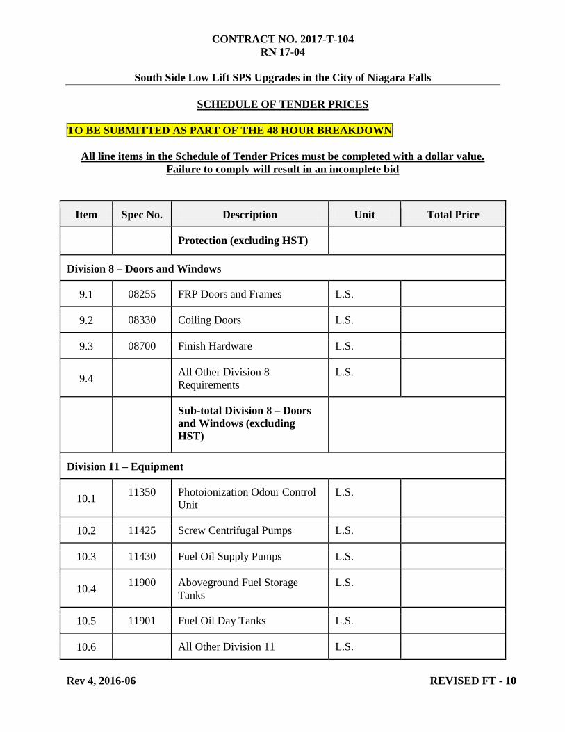
SCHEDULE OF TENDER PRICES
TO BE SUBMITTED AS PART OF THE 48 HOUR BREAKDOWN
All line items in the Schedule of Tender Prices must be completed with a dollar value.
Failure to comply will result in an incomplete bid
Rev 4, 2016-06 REVISED FT - 10
Item Spec No. Description Unit Total Price
Protection (excluding HST)
Division 8 – Doors and Windows
9.1 08255 FRP Doors and Frames L.S.
9.2 08330 Coiling Doors L.S.
9.3 08700 Finish Hardware L.S.
9.4 All Other Division 8
Requirements
L.S.
Sub-total Division 8 – Doors
and Windows (excluding
HST)
Division 11 – Equipment
10.1 11350 Photoionization Odour Control
Unit
L.S.
10.2 11425 Screw Centrifugal Pumps L.S.
10.3 11430 Fuel Oil Supply Pumps L.S.
10.4 11900 Aboveground Fuel Storage
Tanks
L.S.
10.5 11901 Fuel Oil Day Tanks L.S.
10.6 All Other Division 11 L.S.
Water and Wastewater Services
Commissioning Guideline
Commissioning Guideline Region of Niagara
Rev 00
Page 2
Commissioning Guideline
Revision Date Description of Revisions 00 2017-01-19 First Edition of the Commissioning Guideline
Commissioning Guideline Region of Niagara
Rev 00
Page i
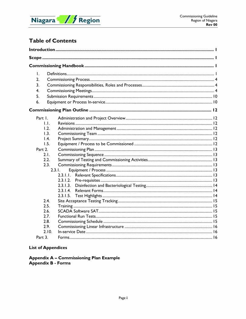
Table of Contents Introduction ................................................................................................................................... 1
Scope .............................................................................................................................................. 1
Commissioning Handbook ........................................................................................................... 1
1. Definitions ......................................................................................................................................................... 1 2. Commissioning Process ................................................................................................................................. 4 3. Commissioning Responsibilities, Roles and Processes ........................................................................... 4 4. Commissioning Meetings............................................................................................................................... 4 5. Submission Requirements ........................................................................................................................... 10 6. Equipment or Process In-service ............................................................................................................... 10
Commissioning Plan Outline ..................................................................................................... 12
Part 1. Administration and Project Overview .......................................................................................... 12 1.1. Revisions .............................................................................................................................................. 12 1.2. Administration and Management ................................................................................................... 12 1.3. Commissioning Team ....................................................................................................................... 12 1.4. Project Summary ................................................................................................................................ 12 1.5. Equipment / Process to be Commissioned ................................................................................. 12
Part 2. Commissioning Plan .......................................................................................................................... 13 2.1. Commissioning Sequence ................................................................................................................ 13 2.2. Summary of Testing and Commissioning Activities ................................................................... 13 2.3. Commissioning Requirements ........................................................................................................ 13
2.3.1. Equipment / Process .............................................................................................................. 13 2.3.1.1. Relevant Specifications .................................................................................................... 13 2.3.1.2. Pre-requisites .................................................................................................................... 13 2.3.1.3. Disinfection and Bacteriological Testing ..................................................................... 14 2.3.1.4. Relevant Forms ................................................................................................................. 14 2.3.1.5. Test Highlights .................................................................................................................. 14
2.4. Site Acceptance Testing Tracking .................................................................................................. 15 2.5. Training ................................................................................................................................................ 15 2.6. SCADA Software SAT ...................................................................................................................... 15 2.7. Functional Run Tests ......................................................................................................................... 15 2.8. Commissioning Schedule ................................................................................................................. 15 2.9. Commissioning Linear Infrastructure ........................................................................................... 16 2.10. In-service Date ................................................................................................................................... 16
Part 3. Forms .................................................................................................................................................... 16 List of Appendices Appendix A – Commissioning Plan Example Appendix B - Forms
Commissioning Guideline Region of Niagara
Rev 00
Page 1
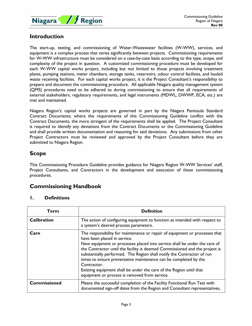
Introduction The start-up, testing, and commissioning of Water-Wastewater facilities (W-WW), services, and equipment is a complex process that varies significantly between projects. Commissioning requirements for W-WW infrastructure must be considered on a case-by-case basis according to the type, scope, and complexity of the project in question. A customized commissioning procedure must be developed for each W-WW capital works project, including but not limited to those projects involving treatment plants, pumping stations, meter chambers, storage tanks, reservoirs, odour control facilities, and hauled waste receiving facilities. For each capital works project, it is the Project Consultant’s responsibility to prepare and document the commissioning procedure. All applicable Niagara quality management system (QMS) procedures need to be adhered to during commissioning to ensure that all requirements of external stakeholders, regulatory requirements, and legal instruments (MDWL, DWWP, ECA, etc.) are met and maintained. Niagara Region’s capital works projects are governed in part by the Niagara Peninsula Standard Contract Documents; where the requirements of this Commissioning Guideline conflict with the Contract Documents, the more stringent of the requirements shall be applied. The Project Consultant is required to identify any deviations from the Contract Documents or the Commissioning Guideline and shall provide written documentation and reasoning for said deviations. Any submissions from other Project Contractors must be reviewed and approved by the Project Consultant before they are submitted to Niagara Region. Scope This Commissioning Procedure Guideline provides guidance for Niagara Region W-WW Services’ staff, Project Consultants, and Contractors in the development and execution of these commissioning procedures. Commissioning Handbook 1. Definitions
Term Definition
Calibration The action of configuring equipment to function as intended with respect to a system’s desired process parameters.
Care The responsibility for maintenance or repair of equipment or processes that have been placed in service. New equipment or processes placed into service shall be under the care of the Contractor until the facility is deemed Commissioned and the project is substantially performed. The Region shall notify the Contractor of run times to ensure preventative maintenance can be completed by the Contractor. Existing equipment shall be under the care of the Region until that equipment or process is removed from service.
Commissioned Means the successful completion of the Facility Functional Run Test with documented sign-off dates from the Region and Consultant representatives,
Commissioning Guideline Region of Niagara
Rev 00
Page 2
Term Definition
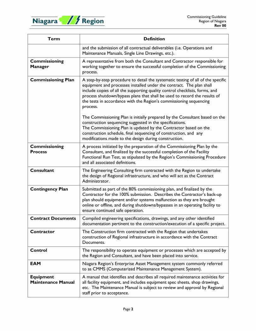
and the submission of all contractual deliverables (i.e. Operations and Maintenance Manuals, Single Line Drawings, etc.).
Commissioning Manager
A representative from both the Consultant and Contractor responsible for working together to ensure the successful completion of the Commissioning process.
Commissioning Plan A step-by-step procedure to detail the systematic testing of all of the specific equipment and processes installed under the contract. The plan shall include copies of all the supporting quality control checklists, forms, and process shutdown/bypass plans that shall be used to record the results of the tests in accordance with the Region’s commissioning sequencing process. The Commissioning Plan is initially prepared by the Consultant based on the construction sequencing suggested in the specifications. The Commissioning Plan is updated by the Contractor based on the construction schedule, final sequencing of construction, and any modifications made to the design during construction.
Commissioning Process
A process initiated by the preparation of the Commissioning Plan by the Consultant, and finalized by the successful completion of the Facility Functional Run Test, as stipulated by the Region’s Commissioning Procedure and all associated definitions.
Consultant The Engineering Consulting firm contracted with the Region to undertake the design of Regional infrastructure, and who will act as the Contract Administrator.
Contingency Plan Submitted as part of the 80% commissioning plan, and finalized by the Contractor for the 100% submission. Describes the Contractor’s back-up plan should equipment and/or systems malfunction as they are brought online or offline, and during shutdowns/bypasses in an operating facility to ensure continued safe operation.
Contract Documents Compiled engineering specifications, drawings, and any other identified documentation pertinent to the construction/execution of a specific project.
Contractor The Construction firm contracted with the Region that undertakes construction of Regional infrastructure in accordance with the Contract Documents.
Control The responsibility to operate equipment or processes which are accepted by the Region and Consultant, and have been placed into service.
EAM Niagara Region’s Enterprise Asset Management system commonly referred to as CMMS (Computerized Maintenance Management System).
Equipment Maintenance Manual
A manual that identifies and describes all required maintenance activities for all facility equipment, and includes equipment spec sheets, shop drawings, etc. The Maintenance Manual is subject to review and approval by Regional staff prior to acceptance.
Commissioning Guideline Region of Niagara
Rev 00
Page 3
Term Definition
Facility Entire horizontal and/or vertical infrastructure including all individual unit processes.
Facility Functional Run Test
A Functional Run Test completed at the end of the Commissioning process to ensure that all new or modified equipment or processes, controls, and programming successfully function within overall facility operation.
Factory Acceptance Testing (FAT)
Testing performed on specified equipment at the manufacturer’s facility prior to shipment. No equipment can be shipped without FAT approval by the Consultant. The Region and Consultant may elect to participate in the FAT process if deemed necessary.
Functional Run Test Testing over a specified duration the operation of each piece of equipment, or process, installed or modified as a part of the project, to determine whether it functions as required.
In-service In-service refers to equipment or a process being operational within the facility’s entirety, and used for its intended final purpose(s), and under the Region’s control.
Network Testing Cable acceptance testing, network closets SAT, basic network connectivity tests, and link acceptance tests. Region and Consultant may elect to participate in the Network Testing process if deemed necessary.
Operations Manual A manual that highlights the operation of the facility, describing the function of the facility and all associated processes. The Operations Manual is subject to review and approval by Regional staff prior to acceptance.
Process A unit within the overall operation of the facility that performs a specific function.
Process Control Narrative
Also described as SCADA Process Narrative this is an updated Process Narrative identifying the operation of the facility and the degree of automation. It identifies the actions that are to be completed by an operator, and the semi-automatic and/or automatic actions of the facility SCADA System. 80% version produced by the Consultant during design. 100% version produced by the Contractor’s SCADA integrator, and shall include a SCADA software requirements document describing the specific algorithms and content required in the RPU and SCADA computer programs.
Process Narrative A written description of key items and procedures of a specific process prepared by the Consultant. The Process Narrative outlines the sequence of operations in Normal, Maintenance, and Emergency conditions, each in manual and automatic modes of control.
Red-line Drawings Drawing sets marked up in red and submitted by the contractor to reflect all changes made in the specifications and working drawings during the construction process, and show the exact dimensions, geometry, and location of all elements of the work completed under the contract.
Site Acceptance A test, or tests, performed after start-up on individual pieces of equipment,
Commissioning Guideline Region of Niagara
Rev 00
Page 4
Term Definition
Testing (SAT) processes, or software/program to demonstrate and confirm that the equipment, process, or software/program meet the specified operational performance requirements. The SAT shall be carried out in the presence of the Contractor, Supplier/Manufacturer, Consultant and the Region.
Start-up The Contractor, in conjunction with manufacturers / suppliers, ensuring that specific equipment or processes are: as specified; installed correctly; calibrated, and certified. Start-up will be witnessed, documented and signed-off by the manufacturer/supplier. No sign-off requirement from the Consultant or Region. The Region and Consultant may elect to participate in the Start-up process if deemed necessary.
Training Site / class instruction of Regional staff on the operation and maintenance of the new equipment/process. Training is to occur following the SAT and prior to the Functional Run Test. Contractor / SCADA Integrator are responsible for scheduling and facilitating equipment and SCADA training. Consultant is responsible for scheduling and facilitating process training.
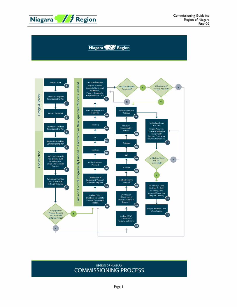
2. Commissioning Process Figure 1 outlines the overall Commissioning Process that is to be followed when preparing a project specific Commissioning Plan 3. Commissioning Responsibilities, Roles and Processes Table 1 details the requirements and roles / responsibilities for each task within the Commissioning Process. 4. Commissioning Meetings The Consultant will meet with Niagara Region’s Project team to review and finalize the plan prior to tendering, based on the Consultant’s suggested construction sequencing and Niagara Region’s operational constraints. Commissioning Plan Review Meeting(s) during construction will be held between the Niagara Region, Contract Administrator, and Contractor Project Teams to discuss and finalize the Commissioning Plan based on final construction sequencing, schedule, and operational constraints.
Commissioning Guideline Region of Niagara
Rev 00
Page 1
Commissioning Guideline Region of Niagara
Rev 00
Page 2
Table 1
Task ID Description Responsibility
Region Consultant Contractor
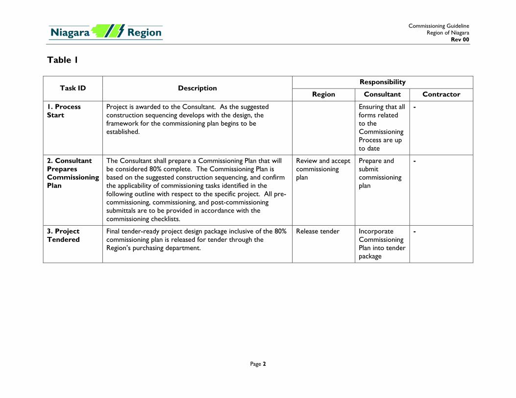
1. Process Start
Project is awarded to the Consultant. As the suggested construction sequencing develops with the design, the framework for the commissioning plan begins to be established.
Ensuring that all forms related to the Commissioning Process are up to date
-
2. Consultant Prepares Commissioning Plan
The Consultant shall prepare a Commissioning Plan that will be considered 80% complete. The Commissioning Plan is based on the suggested construction sequencing, and confirm the applicability of commissioning tasks identified in the following outline with respect to the specific project. All pre-commissioning, commissioning, and post-commissioning submittals are to be provided in accordance with the commissioning checklists.
Review and accept commissioning plan
Prepare and submit commissioning plan
-
3. Project Tendered
Final tender-ready project design package inclusive of the 80% commissioning plan is released for tender through the Region’s purchasing department.
Release tender Incorporate Commissioning Plan into tender package
-
Commissioning Guideline Region of Niagara
Rev 00
Page 3
Task ID Description Responsibility
Region Consultant Contractor
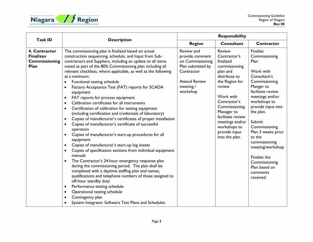
4. Contractor Finalizes Commissioning Plan
The commissioning plan is finalized based on actual construction sequencing, schedule, and Input from Sub-contractors and Suppliers, including an update to all items noted as part of the 80% Commissioning plan including all relevant checklists, where applicable, as well as the following at a minimum: • Functional testing schedule • Factory Acceptance Test (FAT) reports for SCADA
equipment • FAT reports for process equipment • Calibration certificates for all instruments • Certification of calibration for testing equipment
(including certification and credentials of laboratory) • Copies of manufacturer’s certificates of proper installation • Copies of manufacturer’s certificate of successful
operation • Copies of manufacturer’s start-up procedures for all
equipment • Copies of manufacturer’s start-up log sheets • Copies of specification sections from individual equipment
manuals • The Contractor’s 24-hour emergency response plan
during the commissioning period. The plan shall be completed with a daytime staffing plan and names, qualifications and telephone numbers of those assigned to off-hour standby duty
• Performance testing schedule • Operational testing schedule • Contingency plan • System Integrator Software Test Plans and Schedules
Review and provide comment on Commissioning Plan submitted by Contractor Attend Review meeting / workshop
Review Contractor’s finalized commissioning plan and distribute to the Region for review Work with Contractor’s Commissioning Manager to facilitate review meetings and/or workshops to provide input into the plan.
Finalize Commissioning Plan Work with Consultant’s Commissioning Manger to facilitate review meetings and/or workshops to provide input into the plan. Submit Commissioning Plan 3 weeks prior to the commissioning meeting/workshop. Finalize the Commissioning Plan based on comments received.
Commissioning Guideline Region of Niagara
Rev 00
Page 4
Task ID Description Responsibility
Region Consultant Contractor
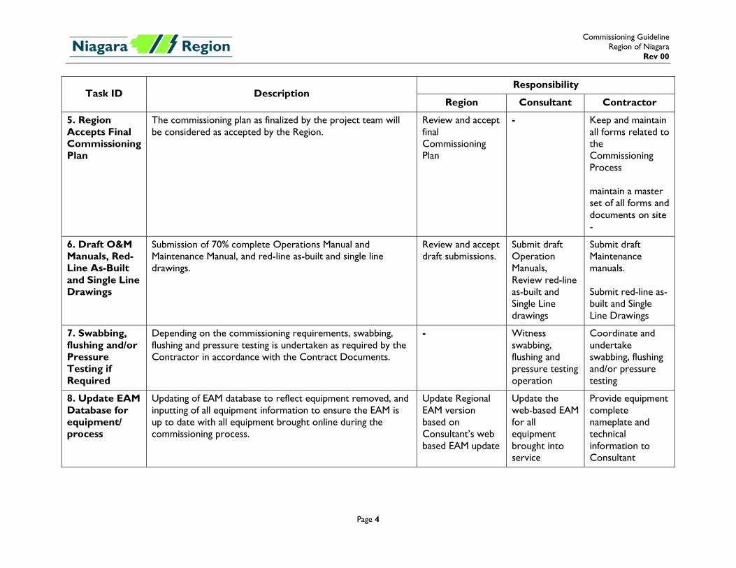
5. Region Accepts Final Commissioning Plan
The commissioning plan as finalized by the project team will be considered as accepted by the Region.
Review and accept final Commissioning Plan
- Keep and maintain all forms related to the Commissioning Process maintain a master set of all forms and documents on site -
6. Draft O&M Manuals, Red-Line As-Built and Single Line Drawings
Submission of 70% complete Operations Manual and Maintenance Manual, and red-line as-built and single line drawings.
Review and accept draft submissions.
Submit draft Operation Manuals, Review red-line as-built and Single Line drawings
Submit draft Maintenance manuals. Submit red-line as-built and Single Line Drawings
7. Swabbing, flushing and/or Pressure Testing if Required
Depending on the commissioning requirements, swabbing, flushing and pressure testing is undertaken as required by the Contractor in accordance with the Contract Documents.
- Witness swabbing, flushing and pressure testing operation
Coordinate and undertake swabbing, flushing and/or pressure testing
8. Update EAM Database for equipment/ process
Updating of EAM database to reflect equipment removed, and inputting of all equipment information to ensure the EAM is up to date with all equipment brought online during the commissioning process.
Update Regional EAM version based on Consultant’s web based EAM update
Update the web-based EAM for all equipment brought into service
Provide equipment complete nameplate and technical information to Consultant
Commissioning Guideline Region of Niagara
Rev 00
Page 5
Task ID Description Responsibility
Region Consultant Contractor
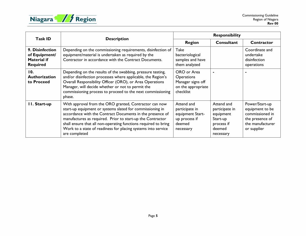
9. Disinfection of Equipment/ Material if Required
Depending on the commissioning requirements, disinfection of equipment/material is undertaken as required by the Contractor in accordance with the Contract Documents.
Take bacteriological samples and have them analyzed
Coordinate and undertake disinfection operations
10. Authorization to Proceed
Depending on the results of the swabbing, pressure testing, and/or disinfection processes where applicable, the Region’s Overall Responsibility Officer (ORO), or Area Operations Manager, will decide whether or not to permit the commissioning process to proceed to the next commissioning phase.
ORO or Area Operations Manager signs off on the appropriate checklist
- -
11. Start-up With approval from the ORO granted, Contractor can now start-up equipment or systems slated for commissioning in accordance with the Contract Documents in the presence of manufactures as required. Prior to start-up the Contractor shall ensure that all non-operating functions required to bring Work to a state of readiness for placing systems into service are completed
Attend and participate in equipment Start-up process if deemed necessary
Attend and participate in equipment Start-up process if deemed necessary
Power/Start-up equipment to be commissioned in the presence of the manufacturer or supplier
Commissioning Guideline Region of Niagara
Rev 00
Page 6
Task ID Description Responsibility
Region Consultant Contractor
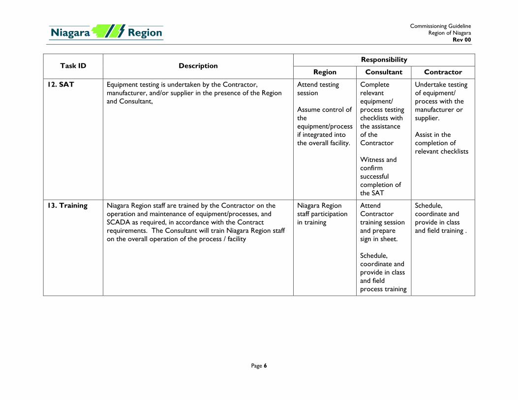
12. SAT Equipment testing is undertaken by the Contractor, manufacturer, and/or supplier in the presence of the Region and Consultant,
Attend testing session Assume control of the equipment/process if integrated into the overall facility.
Complete relevant equipment/ process testing checklists with the assistance of the Contractor Witness and confirm successful completion of the SAT
Undertake testing of equipment/ process with the manufacturer or supplier. Assist in the completion of relevant checklists
13. Training Niagara Region staff are trained by the Contractor on the operation and maintenance of equipment/processes, and SCADA as required, in accordance with the Contract requirements. The Consultant will train Niagara Region staff on the overall operation of the process / facility
Niagara Region staff participation in training
Attend Contractor training session and prepare sign in sheet. Schedule, coordinate and provide in class and field process training
Schedule, coordinate and provide in class and field training .
Commissioning Guideline Region of Niagara
Rev 00
Page 7
Task ID Description Responsibility
Region Consultant Contractor
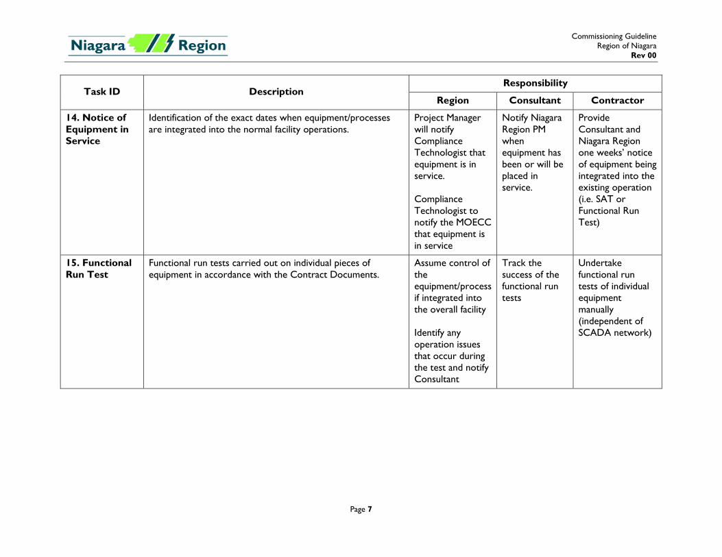
14. Notice of Equipment in Service
Identification of the exact dates when equipment/processes are integrated into the normal facility operations.
Project Manager will notify Compliance Technologist that equipment is in service. Compliance Technologist to notify the MOECC that equipment is in service
Notify Niagara Region PM when equipment has been or will be placed in service.
Provide Consultant and Niagara Region one weeks’ notice of equipment being integrated into the existing operation (i.e. SAT or Functional Run Test)
15. Functional Run Test
Functional run tests carried out on individual pieces of equipment in accordance with the Contract Documents.
Assume control of the equipment/process if integrated into the overall facility Identify any operation issues that occur during the test and notify Consultant
Track the success of the functional run tests
Undertake functional run tests of individual equipment manually (independent of SCADA network)
Commissioning Guideline Region of Niagara
Rev 00
Page 8
Task ID Description Responsibility
Region Consultant Contractor
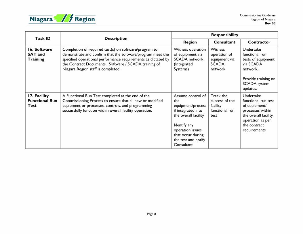
16. Software SAT and Training
Completion of required test(s) on software/program to demonstrate and confirm that the software/program meet the specified operational performance requirements as dictated by the Contract Documents. Software / SCADA training of Niagara Region staff is completed.
Witness operation of equipment via SCADA network (Integrated Systems)
Witness operation of equipment via SCADA network
Undertake functional run tests of equipment via SCADA network. Provide training on SCADA system updates.
17. Facility Functional Run Test
A Functional Run Test completed at the end of the Commissioning Process to ensure that all new or modified equipment or processes, controls, and programming successfully function within overall facility operation.
Assume control of the equipment/process if integrated into the overall facility Identify any operation issues that occur during the test and notify Consultant
Track the success of the facility functional run test
Undertake functional run test of equipment/ processes within the overall facility operation as per the contract requirements
Commissioning Guideline Region of Niagara
Rev 00
Page 9
Task ID Description Responsibility
Region Consultant Contractor
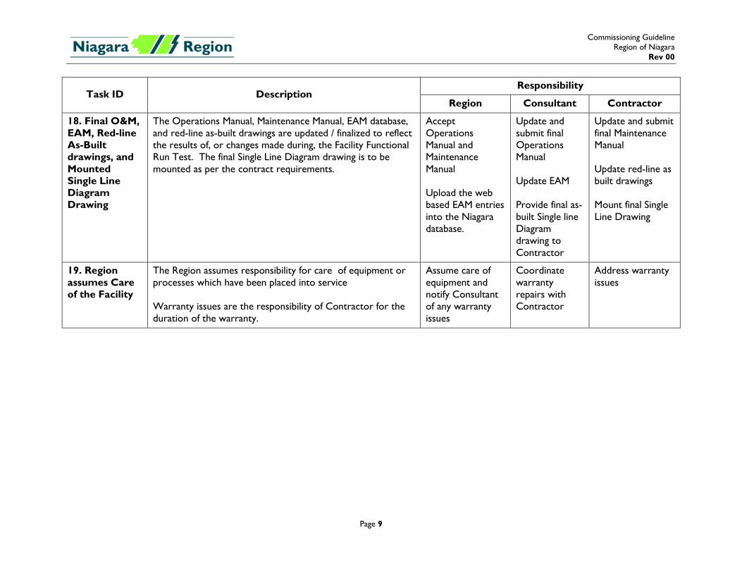
18. Final O&M, EAM, Red-line As-Built drawings, and Mounted Single Line Diagram Drawing
The Operations Manual, Maintenance Manual, EAM database, and red-line as-built drawings are updated / finalized to reflect the results of, or changes made during, the Facility Functional Run Test. The final Single Line Diagram drawing is to be mounted as per the contract requirements.
Accept Operations Manual and Maintenance Manual Upload the web based EAM entries into the Niagara database.
Update and submit final Operations Manual Update EAM Provide final as-built Single line Diagram drawing to Contractor
Update and submit final Maintenance Manual Update red-line as built drawings Mount final Single Line Drawing
19. Region assumes Care of the Facility
The Region assumes responsibility for care of equipment or processes which have been placed into service Warranty issues are the responsibility of Contractor for the duration of the warranty.
Assume care of equipment and notify Consultant of any warranty issues
Coordinate warranty repairs with Contractor
Address warranty issues
Commissioning Guideline Region of Niagara
Rev 00
Page 10
5. Submission Requirements As part of the Commissioning Process, both the Consultant and the Contractor are required to submit documents at various stages throughout the process. The Consultant will provide a draft copy of the Commissioning Plan, and the Operations Manual or Update, to Niagara Region for review as part of the Detailed Engineering Design Review submission. Comments / edits received from Niagara Region will be incorporated into each document prior to the project being tendered. The Contractor will provide a draft copy of the final Commissioning Plan to the Contract Administrator’s Commissioning Manager for review by the Contract Administrator and Niagara Region. Comments / edits received during review meetings will be incorporated into the final Commissioning Plan. This process may require multiple submissions before the Plan is accepted. Prior to the start of the Commissioning Process testing stage(s) the Contractor must ensure that the following is submitted or complete:
a) Final Commissioning Plan is accepted; b) All asset information for the equipment, process, or facility is entered into Niagara Region’s
EAM; c) Draft Maintenance Manual is accepted by Contract Administrator and Niagara Region, and is
available on-site; d) Red-line as-built drawings are up to date; and e) Red-line as-built Single Line Diagram is completed and available on-site.
Prior to Niagara Region accepting full care and control of the facility, and the Commissioning Process deemed complete, the Consultant and the Contractor must ensure that submitted or completed:
a) Asset information changed during the testing stage(s) is updated in EAM; b) Final red-line as-built drawings are provided to the Consultant; c) Final Single Line Diagram as-built is completed and mounted as per the specifications; and d) Final Operations Manual and Maintenance Manual provided to Niagara Region as per the
specifications. Keeping in mind that some submissions may have multiple iterations before being finalized, the Consultant and Contractor should allow sufficient time for multiple reviews and meetings in their schedules. 6. Equipment or Process In-service It is crucial for compliance purposes that the in-service date for all equipment and/or processes is recorded. The in-service milestone may vary and is dependent on test requirement (i.e. does the equipment or process need to be online to test?). Prior to being placed in-service the Region’s Area Operations Manager will sign-off indicating approval for the equipment or process to be placed in service. The in-service date must reflect the first day that the equipment or process is operational within the facility’s entirety, and used for its intended final purpose(s), and under the Region’s control.

Commissioning Guideline Region of Niagara
Rev 00
Page 11
Distribute updated forms to the identified commissioning team members as each piece of equipment and / or process is placed in-service.
Commissioning Guideline Region of Niagara
Rev 00
Page 12
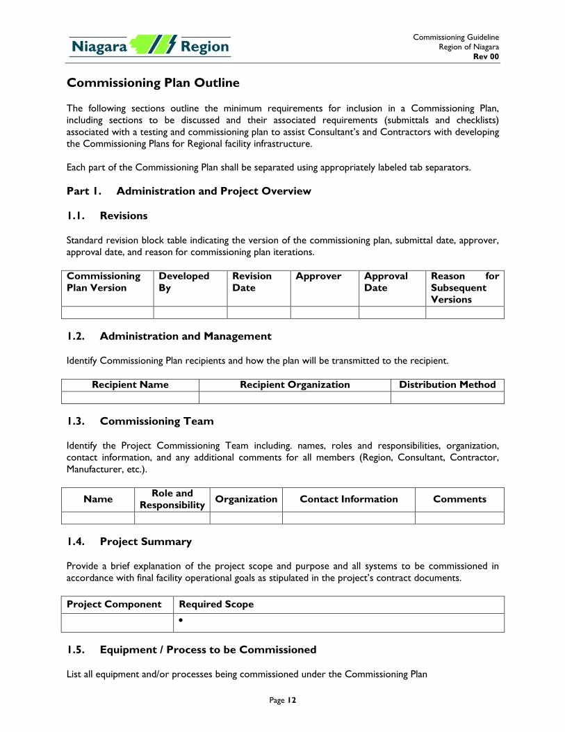
Commissioning Plan Outline The following sections outline the minimum requirements for inclusion in a Commissioning Plan, including sections to be discussed and their associated requirements (submittals and checklists) associated with a testing and commissioning plan to assist Consultant’s and Contractors with developing the Commissioning Plans for Regional facility infrastructure. Each part of the Commissioning Plan shall be separated using appropriately labeled tab separators. Part 1. Administration and Project Overview 1.1. Revisions Standard revision block table indicating the version of the commissioning plan, submittal date, approver, approval date, and reason for commissioning plan iterations. Commissioning Plan Version
Developed By
Revision Date
Approver Approval Date
Reason for Subsequent Versions
1.2. Administration and Management Identify Commissioning Plan recipients and how the plan will be transmitted to the recipient.
Recipient Name Recipient Organization Distribution Method 1.3. Commissioning Team Identify the Project Commissioning Team including. names, roles and responsibilities, organization, contact information, and any additional comments for all members (Region, Consultant, Contractor, Manufacturer, etc.).
Name Role and Responsibility Organization Contact Information Comments
1.4. Project Summary Provide a brief explanation of the project scope and purpose and all systems to be commissioned in accordance with final facility operational goals as stipulated in the project’s contract documents. Project Component Required Scope •
1.5. Equipment / Process to be Commissioned List all equipment and/or processes being commissioned under the Commissioning Plan
Commissioning Guideline Region of Niagara
Rev 00
Page 13
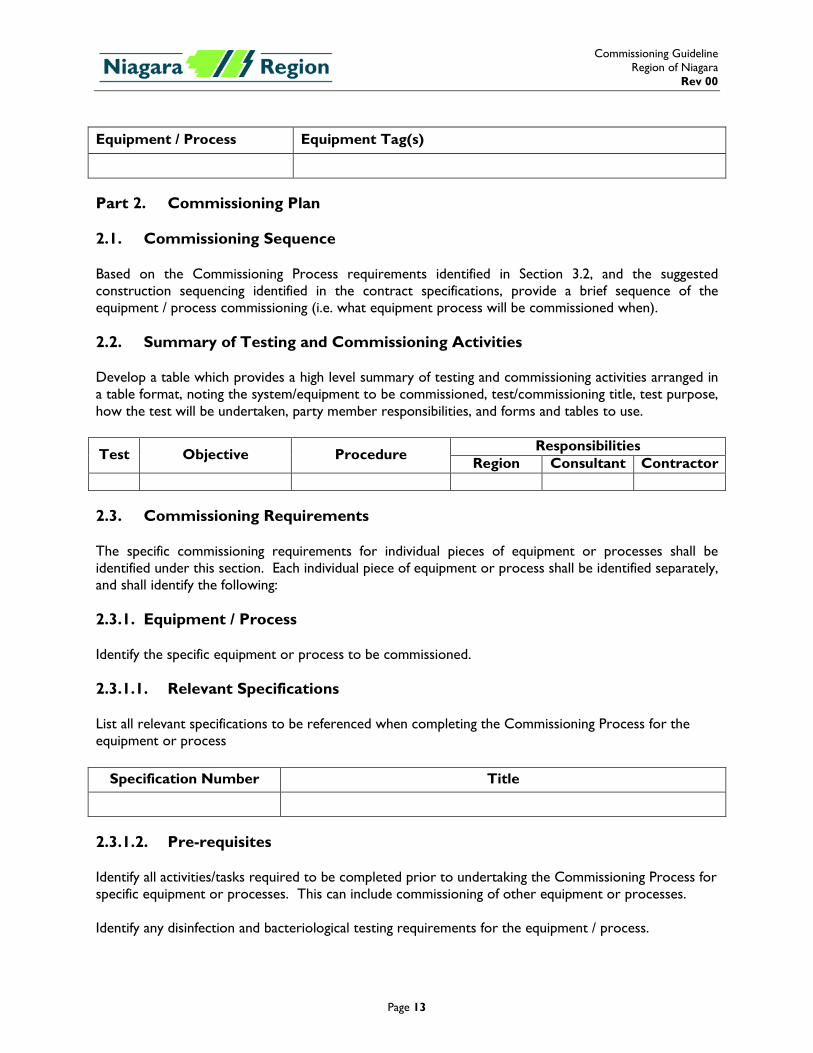
Equipment / Process Equipment Tag(s)
Part 2. Commissioning Plan 2.1. Commissioning Sequence Based on the Commissioning Process requirements identified in Section 3.2, and the suggested construction sequencing identified in the contract specifications, provide a brief sequence of the equipment / process commissioning (i.e. what equipment process will be commissioned when). 2.2. Summary of Testing and Commissioning Activities Develop a table which provides a high level summary of testing and commissioning activities arranged in a table format, noting the system/equipment to be commissioned, test/commissioning title, test purpose, how the test will be undertaken, party member responsibilities, and forms and tables to use.
Test Objective Procedure Responsibilities Region Consultant Contractor
2.3. Commissioning Requirements The specific commissioning requirements for individual pieces of equipment or processes shall be identified under this section. Each individual piece of equipment or process shall be identified separately, and shall identify the following: 2.3.1. Equipment / Process Identify the specific equipment or process to be commissioned. 2.3.1.1. Relevant Specifications List all relevant specifications to be referenced when completing the Commissioning Process for the equipment or process
Specification Number Title
2.3.1.2. Pre-requisites Identify all activities/tasks required to be completed prior to undertaking the Commissioning Process for specific equipment or processes. This can include commissioning of other equipment or processes. Identify any disinfection and bacteriological testing requirements for the equipment / process.
Commissioning Guideline Region of Niagara
Rev 00
Page 14
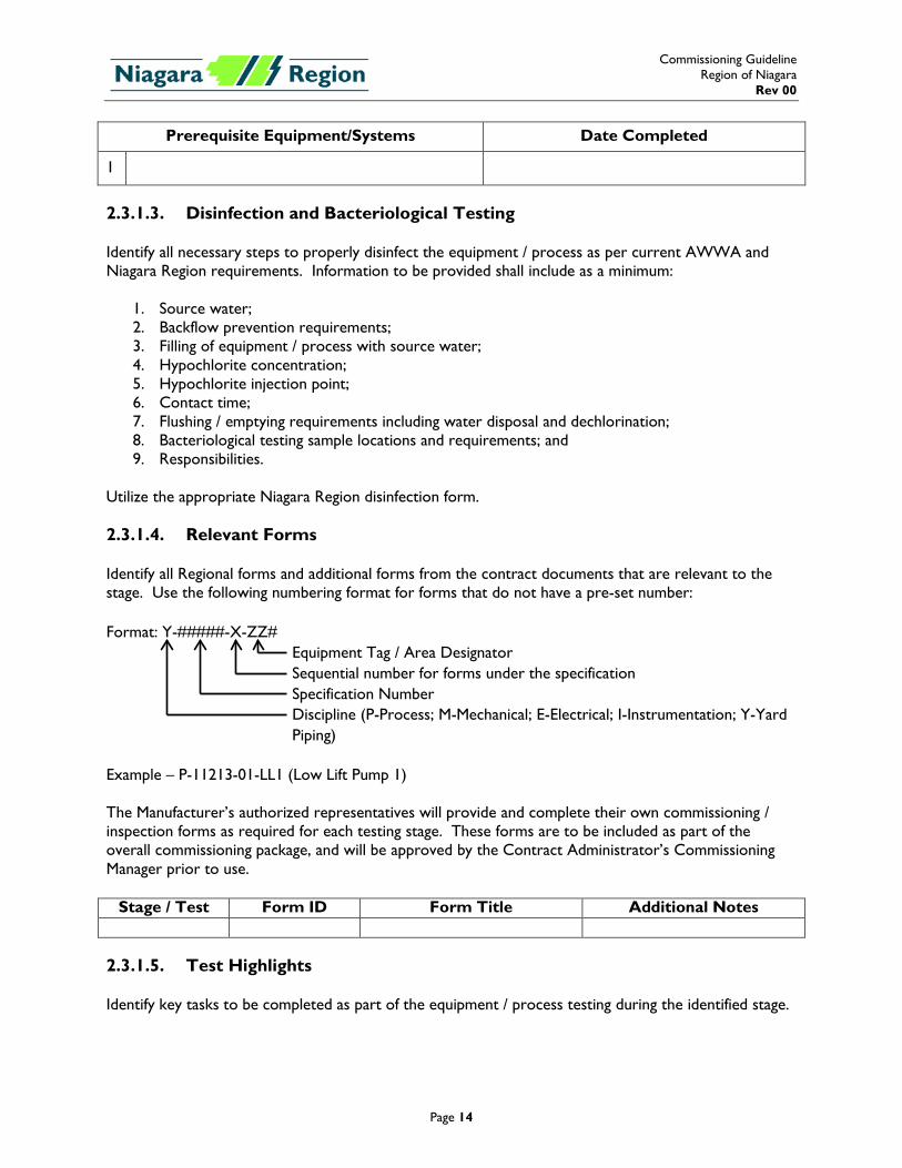
Prerequisite Equipment/Systems Date Completed
1
2.3.1.3. Disinfection and Bacteriological Testing Identify all necessary steps to properly disinfect the equipment / process as per current AWWA and Niagara Region requirements. Information to be provided shall include as a minimum:
1. Source water; 2. Backflow prevention requirements; 3. Filling of equipment / process with source water; 4. Hypochlorite concentration; 5. Hypochlorite injection point; 6. Contact time; 7. Flushing / emptying requirements including water disposal and dechlorination; 8. Bacteriological testing sample locations and requirements; and 9. Responsibilities.
Utilize the appropriate Niagara Region disinfection form. 2.3.1.4. Relevant Forms Identify all Regional forms and additional forms from the contract documents that are relevant to the stage. Use the following numbering format for forms that do not have a pre-set number: Format: Y-#####-X-ZZ#
Equipment Tag / Area Designator Sequential number for forms under the specification Specification Number Discipline (P-Process; M-Mechanical; E-Electrical; I-Instrumentation; Y-Yard Piping)
Example – P-11213-01-LL1 (Low Lift Pump 1) The Manufacturer’s authorized representatives will provide and complete their own commissioning / inspection forms as required for each testing stage. These forms are to be included as part of the overall commissioning package, and will be approved by the Contract Administrator’s Commissioning Manager prior to use.
Stage / Test Form ID Form Title Additional Notes 2.3.1.5. Test Highlights Identify key tasks to be completed as part of the equipment / process testing during the identified stage.
Commissioning Guideline Region of Niagara
Rev 00
Page 15
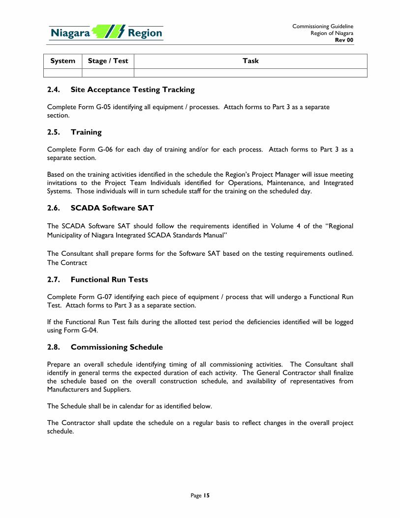
System Stage / Test Task
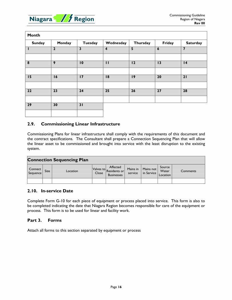
2.4. Site Acceptance Testing Tracking Complete Form G-05 identifying all equipment / processes. Attach forms to Part 3 as a separate section. 2.5. Training Complete Form G-06 for each day of training and/or for each process. Attach forms to Part 3 as a separate section. Based on the training activities identified in the schedule the Region’s Project Manager will issue meeting invitations to the Project Team Individuals identified for Operations, Maintenance, and Integrated Systems. Those individuals will in turn schedule staff for the training on the scheduled day. 2.6. SCADA Software SAT The SCADA Software SAT should follow the requirements identified in Volume 4 of the “Regional Municipality of Niagara Integrated SCADA Standards Manual” The Consultant shall prepare forms for the Software SAT based on the testing requirements outlined. The Contract 2.7. Functional Run Tests Complete Form G-07 identifying each piece of equipment / process that will undergo a Functional Run Test. Attach forms to Part 3 as a separate section. If the Functional Run Test fails during the allotted test period the deficiencies identified will be logged using Form G-04. 2.8. Commissioning Schedule Prepare an overall schedule identifying timing of all commissioning activities. The Consultant shall identify in general terms the expected duration of each activity. The General Contractor shall finalize the schedule based on the overall construction schedule, and availability of representatives from Manufacturers and Suppliers. The Schedule shall be in calendar for as identified below. The Contractor shall update the schedule on a regular basis to reflect changes in the overall project schedule.
Commissioning Guideline Region of Niagara
Rev 00
Page 16
Month
Sunday Monday Tuesday Wednesday Thursday Friday Saturday 1 2 3 4 5 6 7
8 9 10 11 12 13 14
15 16 17 18 19 20 21
22 23 24 25 26 27 28
29 30 31
2.9. Commissioning Linear Infrastructure Commissioning Plans for linear infrastructure shall comply with the requirements of this document and the contract specifications. The Consultant shall prepare a Connection Sequencing Plan that will allow the linear asset to be commissioned and brought into service with the least disruption to the existing system.
Connection Sequencing Plan
Connect Sequence Size Location Valves to
Close
Affected Residents or Businesses
Mains in service
Mains not in Service
Source Water
Location Comments
2.10. In-service Date Complete Form G-10 for each piece of equipment or process placed into service. This form is also to be completed indicating the date that Niagara Region becomes responsible for care of the equipment or process. This form is to be used for linear and facility work. Part 3. Forms Attach all forms to this section separated by equipment or process
Page A-1
Appendix A Commissioning Plan Example
Commissioning Guideline Region of Niagara
Rev 00 Appendix A
Page A-1
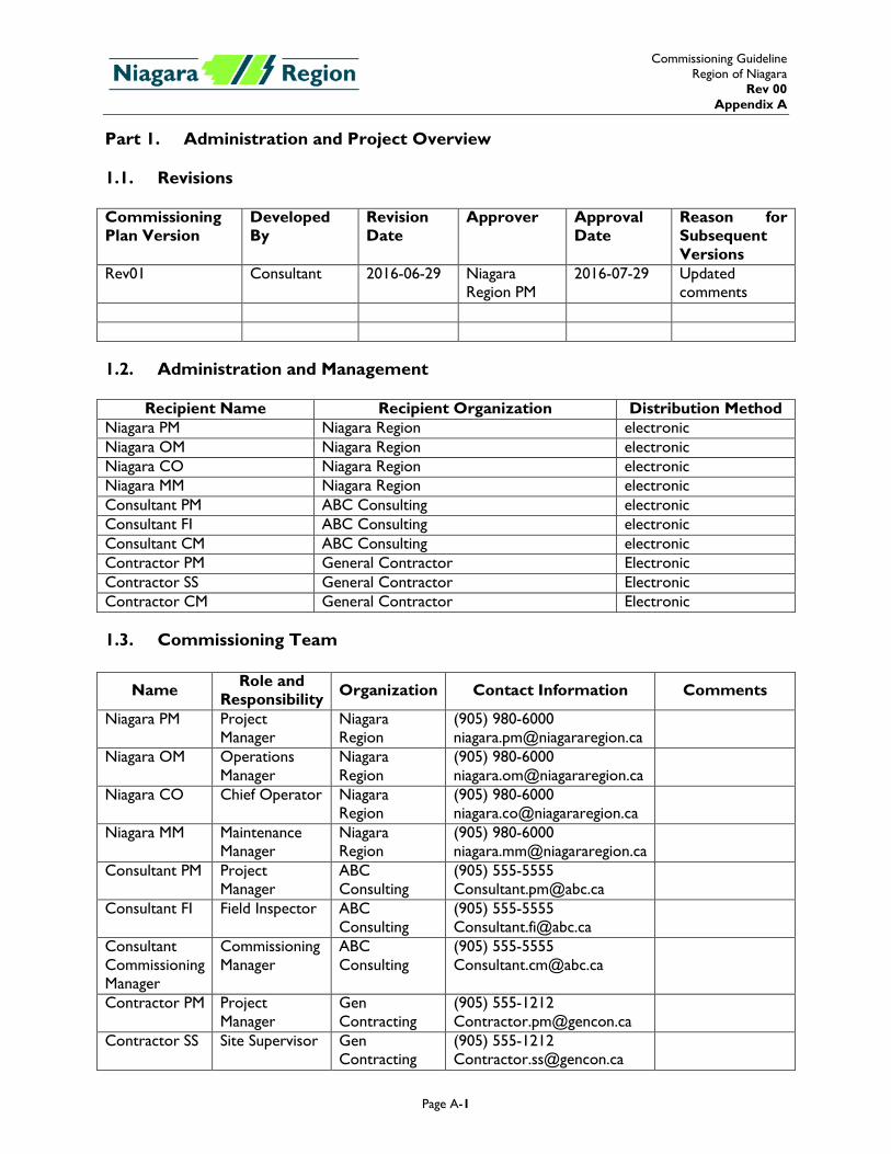
Part 1. Administration and Project Overview
1.1. Revisions
Commissioning Plan Version
Developed By
Revision Date
Approver Approval Date
Reason for Subsequent Versions
Rev01 Consultant 2016-06-29 Niagara Region PM
2016-07-29 Updated comments
1.2. Administration and Management
Recipient Name Recipient Organization Distribution Method
Niagara PM Niagara Region electronic Niagara OM Niagara Region electronic Niagara CO Niagara Region electronic Niagara MM Niagara Region electronic Consultant PM ABC Consulting electronic Consultant FI ABC Consulting electronic Consultant CM ABC Consulting electronic Contractor PM General Contractor Electronic Contractor SS General Contractor Electronic Contractor CM General Contractor Electronic
1.3. Commissioning Team
Name Role and Responsibility Organization Contact Information Comments
Niagara PM Project Manager
Niagara Region
(905) 980-6000 [email protected]
Niagara OM Operations Manager
Niagara Region
(905) 980-6000 [email protected]
Niagara CO Chief Operator Niagara Region
(905) 980-6000 [email protected]
Niagara MM Maintenance Manager
Niagara Region
(905) 980-6000 [email protected]
Consultant PM Project Manager
ABC Consulting
(905) 555-5555 [email protected]
Consultant FI Field Inspector ABC Consulting
(905) 555-5555 [email protected]
Consultant Commissioning Manager
Commissioning Manager
ABC Consulting
(905) 555-5555 [email protected]
Contractor PM Project Manager
Gen Contracting
(905) 555-1212 [email protected]
Contractor SS Site Supervisor Gen Contracting
(905) 555-1212 [email protected]
Commissioning Guideline Region of Niagara
Rev 00 Appendix A
Page A-2
Name Role and Responsibility Organization Contact Information Comments
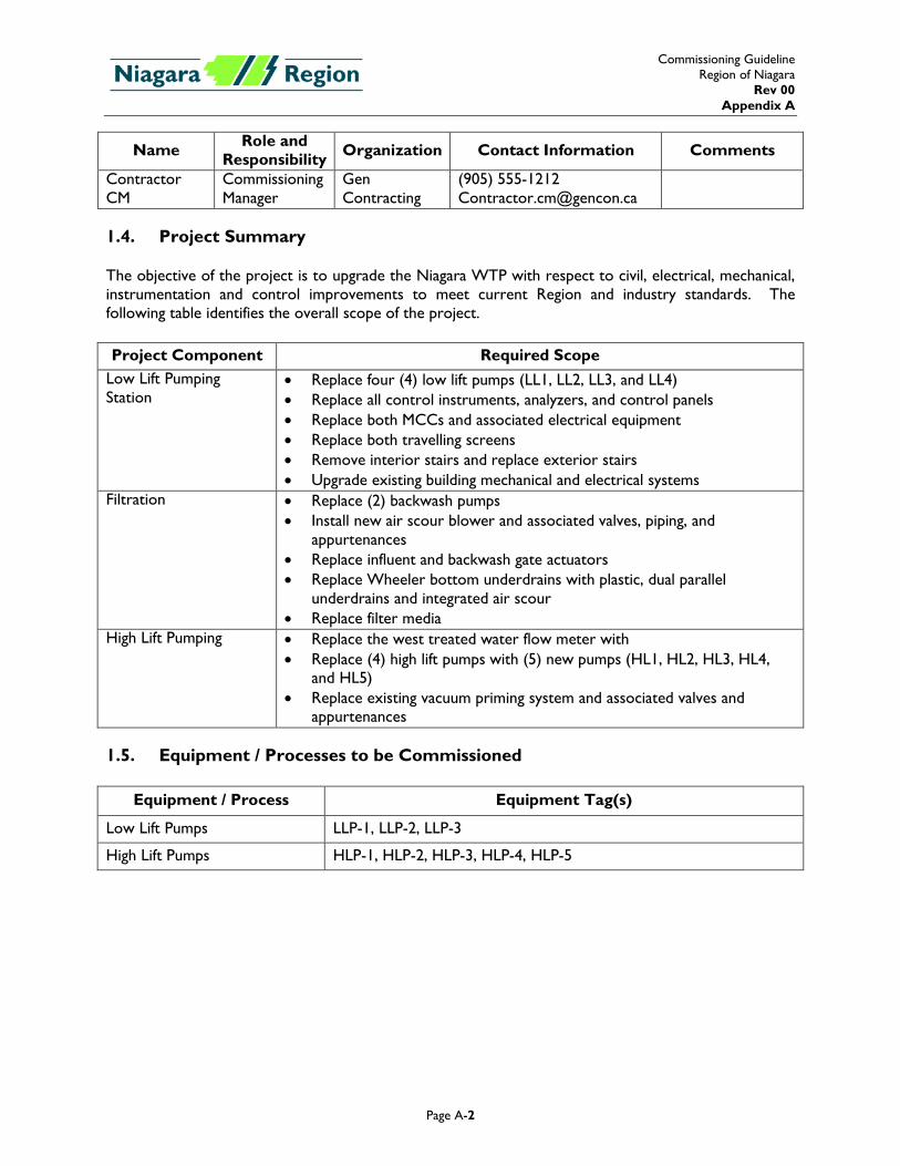
Contractor CM
Commissioning Manager
Gen Contracting
(905) 555-1212 [email protected]
1.4. Project Summary The objective of the project is to upgrade the Niagara WTP with respect to civil, electrical, mechanical, instrumentation and control improvements to meet current Region and industry standards. The following table identifies the overall scope of the project. Project Component Required Scope
Low Lift Pumping Station
• Replace four (4) low lift pumps (LL1, LL2, LL3, and LL4) • Replace all control instruments, analyzers, and control panels • Replace both MCCs and associated electrical equipment • Replace both travelling screens • Remove interior stairs and replace exterior stairs • Upgrade existing building mechanical and electrical systems
Filtration • Replace (2) backwash pumps • Install new air scour blower and associated valves, piping, and
appurtenances • Replace influent and backwash gate actuators • Replace Wheeler bottom underdrains with plastic, dual parallel
underdrains and integrated air scour • Replace filter media
High Lift Pumping • Replace the west treated water flow meter with • Replace (4) high lift pumps with (5) new pumps (HL1, HL2, HL3, HL4,
and HL5) • Replace existing vacuum priming system and associated valves and
appurtenances 1.5. Equipment / Processes to be Commissioned
Equipment / Process Equipment Tag(s)
Low Lift Pumps LLP-1, LLP-2, LLP-3
High Lift Pumps HLP-1, HLP-2, HLP-3, HLP-4, HLP-5
Commissioning Guideline Region of Niagara
Rev 00 Appendix A
Page A-3
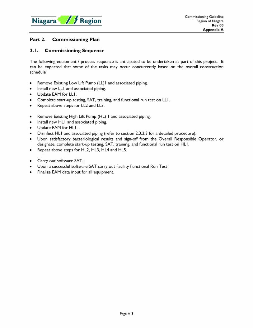
Part 2. Commissioning Plan 2.1. Commissioning Sequence The following equipment / process sequence is anticipated to be undertaken as part of this project. It can be expected that some of the tasks may occur concurrently based on the overall construction schedule • Remove Existing Low Lift Pump (LL)1 and associated piping. • Install new LL1 and associated piping. • Update EAM for LL1. • Complete start-up testing, SAT, training, and functional run test on LL1. • Repeat above steps for LL2 and LL3. • Remove Existing High Lift Pump (HL) 1 and associated piping. • Install new HL1 and associated piping. • Update EAM for HL1. • Disinfect HL1 and associated piping (refer to section 2.3.2.3 for a detailed procedure). • Upon satisfactory bacteriological results and sign-off from the Overall Responsible Operator, or
designate, complete start-up testing, SAT, training, and functional run test on HL1. • Repeat above steps for HL2, HL3, HL4 and HL5. • Carry out software SAT. • Upon a successful software SAT carry out Facility Functional Run Test • Finalize EAM data input for all equipment.
Commissioning Guideline Region of Niagara
Rev 00 Appendix A
Page A-4
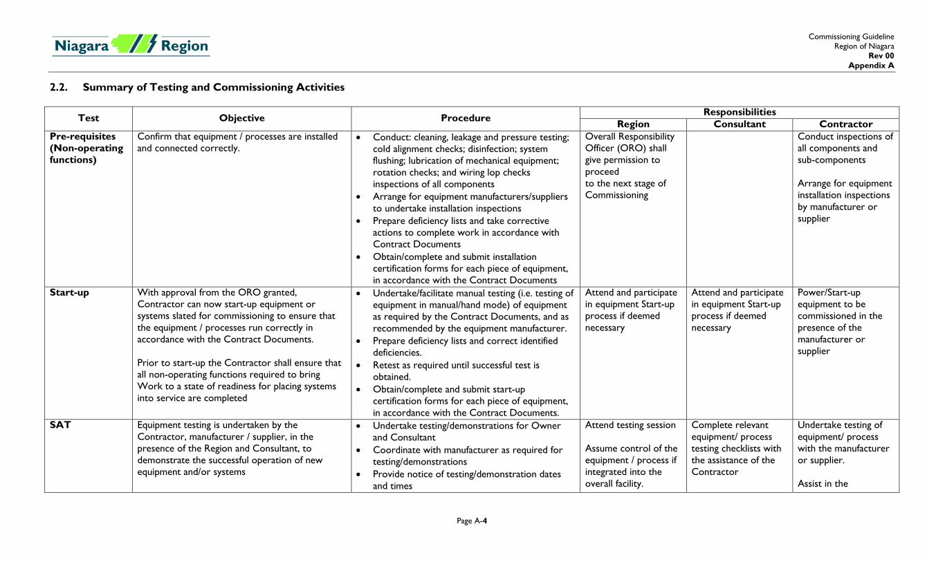
2.2. Summary of Testing and Commissioning Activities
Test Objective Procedure Responsibilities Region Consultant Contractor
Pre-requisites (Non-operating functions)
Confirm that equipment / processes are installed and connected correctly.
• Conduct: cleaning, leakage and pressure testing; cold alignment checks; disinfection; system flushing; lubrication of mechanical equipment; rotation checks; and wiring lop checks inspections of all components
• Arrange for equipment manufacturers/suppliers to undertake installation inspections
• Prepare deficiency lists and take corrective actions to complete work in accordance with Contract Documents
• Obtain/complete and submit installation certification forms for each piece of equipment, in accordance with the Contract Documents
Overall Responsibility Officer (ORO) shall give permission to proceed to the next stage of Commissioning
Conduct inspections of all components and sub-components Arrange for equipment installation inspections by manufacturer or supplier
Start-up With approval from the ORO granted, Contractor can now start-up equipment or systems slated for commissioning to ensure that the equipment / processes run correctly in accordance with the Contract Documents. Prior to start-up the Contractor shall ensure that all non-operating functions required to bring Work to a state of readiness for placing systems into service are completed
• Undertake/facilitate manual testing (i.e. testing of equipment in manual/hand mode) of equipment as required by the Contract Documents, and as recommended by the equipment manufacturer.
• Prepare deficiency lists and correct identified deficiencies.
• Retest as required until successful test is obtained.
• Obtain/complete and submit start-up certification forms for each piece of equipment, in accordance with the Contract Documents.
Attend and participate in equipment Start-up process if deemed necessary
Attend and participate in equipment Start-up process if deemed necessary
Power/Start-up equipment to be commissioned in the presence of the manufacturer or supplier
SAT Equipment testing is undertaken by the Contractor, manufacturer / supplier, in the presence of the Region and Consultant, to demonstrate the successful operation of new equipment and/or systems
• Undertake testing/demonstrations for Owner and Consultant
• Coordinate with manufacturer as required for testing/demonstrations
• Provide notice of testing/demonstration dates and times
Attend testing session Assume control of the equipment / process if integrated into the overall facility.
Complete relevant equipment/ process testing checklists with the assistance of the Contractor
Undertake testing of equipment/ process with the manufacturer or supplier. Assist in the
Commissioning Guideline Region of Niagara
Rev 00 Appendix A
Page A-5
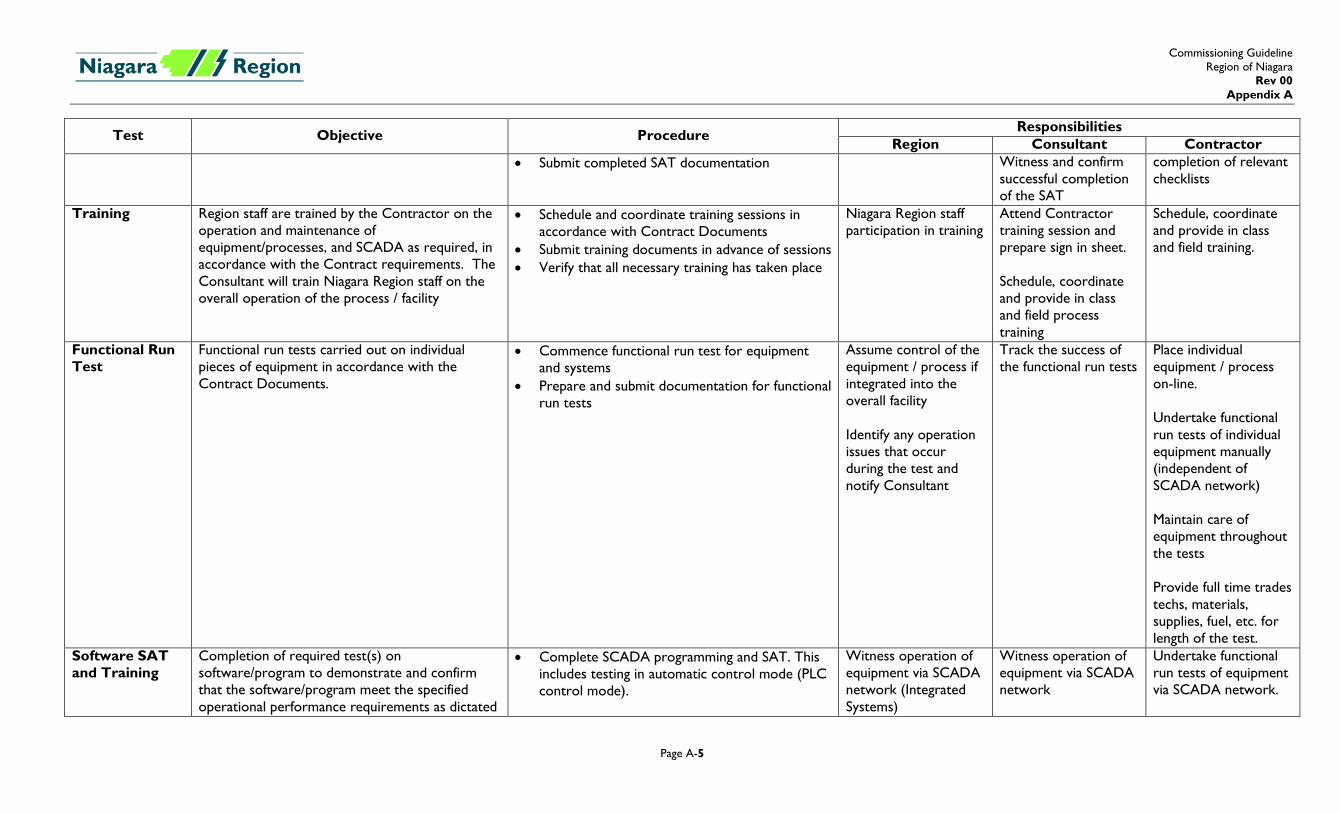
Test Objective Procedure Responsibilities Region Consultant Contractor
• Submit completed SAT documentation Witness and confirm successful completion of the SAT
completion of relevant checklists
Training Region staff are trained by the Contractor on the operation and maintenance of equipment/processes, and SCADA as required, in accordance with the Contract requirements. The Consultant will train Niagara Region staff on the overall operation of the process / facility
• Schedule and coordinate training sessions in accordance with Contract Documents
• Submit training documents in advance of sessions • Verify that all necessary training has taken place
Niagara Region staff participation in training
Attend Contractor training session and prepare sign in sheet. Schedule, coordinate and provide in class and field process training
Schedule, coordinate and provide in class and field training.
Functional Run Test
Functional run tests carried out on individual pieces of equipment in accordance with the Contract Documents.
• Commence functional run test for equipment and systems
• Prepare and submit documentation for functional run tests
Assume control of the equipment / process if integrated into the overall facility Identify any operation issues that occur during the test and notify Consultant
Track the success of the functional run tests
Place individual equipment / process on-line. Undertake functional run tests of individual equipment manually (independent of SCADA network) Maintain care of equipment throughout the tests Provide full time trades techs, materials, supplies, fuel, etc. for length of the test.
Software SAT and Training
Completion of required test(s) on software/program to demonstrate and confirm that the software/program meet the specified operational performance requirements as dictated
• Complete SCADA programming and SAT. This includes testing in automatic control mode (PLC control mode).
Witness operation of equipment via SCADA network (Integrated Systems)
Witness operation of equipment via SCADA network
Undertake functional run tests of equipment via SCADA network.
Commissioning Guideline Region of Niagara
Rev 00 Appendix A
Page A-6
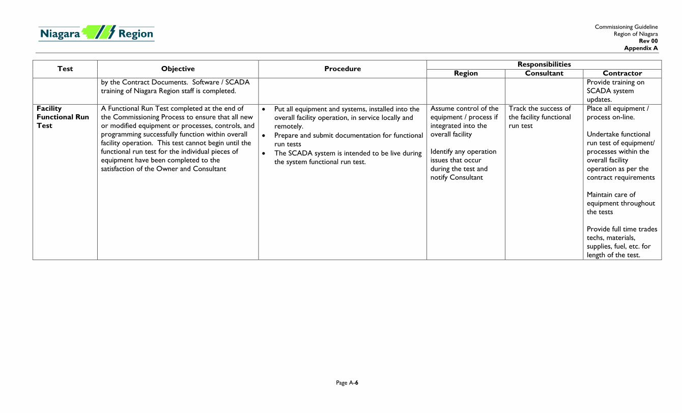
Test Objective Procedure Responsibilities Region Consultant Contractor
by the Contract Documents. Software / SCADA training of Niagara Region staff is completed.
Provide training on SCADA system updates.
Facility Functional Run Test
A Functional Run Test completed at the end of the Commissioning Process to ensure that all new or modified equipment or processes, controls, and programming successfully function within overall facility operation. This test cannot begin until the functional run test for the individual pieces of equipment have been completed to the satisfaction of the Owner and Consultant
• Put all equipment and systems, installed into the overall facility operation, in service locally and remotely.
• Prepare and submit documentation for functional run tests
• The SCADA system is intended to be live during the system functional run test.
Assume control of the equipment / process if integrated into the overall facility Identify any operation issues that occur during the test and notify Consultant
Track the success of the facility functional run test
Place all equipment / process on-line. Undertake functional run test of equipment/ processes within the overall facility operation as per the contract requirements Maintain care of equipment throughout the tests Provide full time trades techs, materials, supplies, fuel, etc. for length of the test.
Commissioning Guideline Region of Niagara
Rev 00 Appendix A
Page A-7
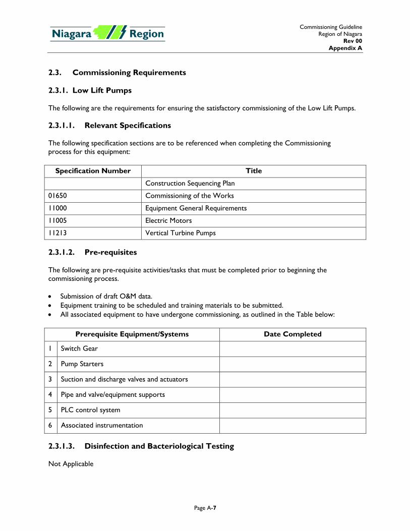
2.3. Commissioning Requirements 2.3.1. Low Lift Pumps The following are the requirements for ensuring the satisfactory commissioning of the Low Lift Pumps. 2.3.1.1. Relevant Specifications The following specification sections are to be referenced when completing the Commissioning process for this equipment:
Specification Number Title
Construction Sequencing Plan
01650 Commissioning of the Works
11000 Equipment General Requirements
11005 Electric Motors
11213 Vertical Turbine Pumps 2.3.1.2. Pre-requisites The following are pre-requisite activities/tasks that must be completed prior to beginning the commissioning process. • Submission of draft O&M data. • Equipment training to be scheduled and training materials to be submitted. • All associated equipment to have undergone commissioning, as outlined in the Table below:
Prerequisite Equipment/Systems Date Completed
1 Switch Gear
2 Pump Starters
3 Suction and discharge valves and actuators
4 Pipe and valve/equipment supports
5 PLC control system
6 Associated instrumentation
2.3.1.3. Disinfection and Bacteriological Testing Not Applicable
Commissioning Guideline Region of Niagara
Rev 00 Appendix A
Page A-8
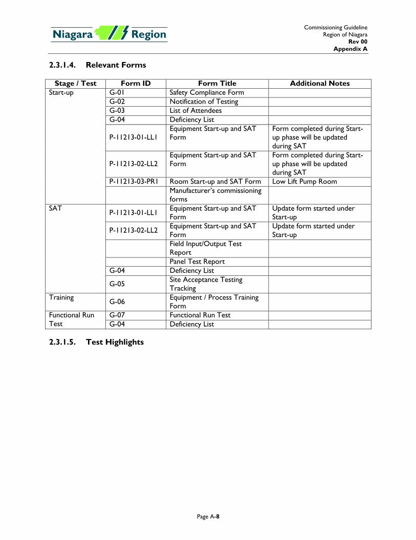
2.3.1.4. Relevant Forms
Stage / Test Form ID Form Title Additional Notes Start-up G-01 Safety Compliance Form
G-02 Notification of Testing G-03 List of Attendees G-04 Deficiency List
P-11213-01-LL1 Equipment Start-up and SAT Form
Form completed during Start-up phase will be updated during SAT
P-11213-02-LL2 Equipment Start-up and SAT Form
Form completed during Start-up phase will be updated during SAT
P-11213-03-PR1 Room Start-up and SAT Form Low Lift Pump Room
Manufacturer’s commissioning forms
SAT P-11213-01-LL1 Equipment Start-up and SAT Form
Update form started under Start-up
P-11213-02-LL2 Equipment Start-up and SAT Form
Update form started under Start-up
Field Input/Output Test Report
Panel Test Report G-04 Deficiency List
G-05 Site Acceptance Testing Tracking
Training G-06 Equipment / Process Training Form
Functional Run Test
G-07 Functional Run Test G-04 Deficiency List
2.3.1.5. Test Highlights
Commissioning Guideline Region of Niagara
Rev 00 Appendix A
Page A-9
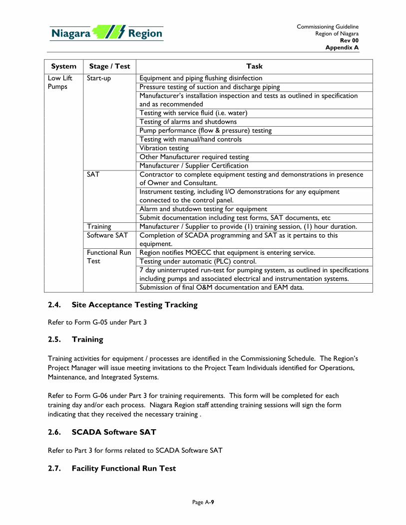
System Stage / Test Task
Low Lift Pumps
Start-up Equipment and piping flushing disinfection Pressure testing of suction and discharge piping Manufacturer’s installation inspection and tests as outlined in specification and as recommended Testing with service fluid (i.e. water) Testing of alarms and shutdowns Pump performance (flow & pressure) testing Testing with manual/hand controls Vibration testing Other Manufacturer required testing Manufacturer / Supplier Certification
SAT Contractor to complete equipment testing and demonstrations in presence of Owner and Consultant. Instrument testing, including I/O demonstrations for any equipment connected to the control panel. Alarm and shutdown testing for equipment Submit documentation including test forms, SAT documents, etc
Training Manufacturer / Supplier to provide (1) training session, (1) hour duration. Software SAT Completion of SCADA programming and SAT as it pertains to this
equipment. Functional Run Test
Region notifies MOECC that equipment is entering service. Testing under automatic (PLC) control. 7 day uninterrupted run-test for pumping system, as outlined in specifications including pumps and associated electrical and instrumentation systems. Submission of final O&M documentation and EAM data.
2.4. Site Acceptance Testing Tracking Refer to Form G-05 under Part 3 2.5. Training Training activities for equipment / processes are identified in the Commissioning Schedule. The Region’s Project Manager will issue meeting invitations to the Project Team Individuals identified for Operations, Maintenance, and Integrated Systems. Refer to Form G-06 under Part 3 for training requirements. This form will be completed for each training day and/or each process. Niagara Region staff attending training sessions will sign the form indicating that they received the necessary training . 2.6. SCADA Software SAT Refer to Part 3 for forms related to SCADA Software SAT 2.7. Facility Functional Run Test
Commissioning Guideline Region of Niagara
Rev 00 Appendix A
Page A-10
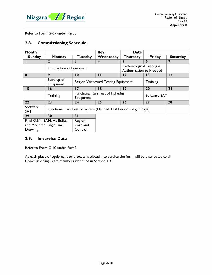
Refer to Form G-07 under Part 3 2.8. Commissioning Schedule Month Rev. Date
Sunday Monday Tuesday Wednesday Thursday Friday Saturday 1 2 3 4 5 6 7
Disinfection of Equipment Bacteriological Testing & Authorization to Proceed
8 9 10 11 12 13 14
Start-up of Equipment Region Witnessed Testing Equipment Training
15 16 17 18 19 20 21
Training Functional Run Test of Individual Equipment Software SAT
22 23 24 25 26 27 28 Software SAT Functional Run Test of System (Defined Test Period – e.g. 5 days)
29 30 31 Final O&M, EAM, As-Builts, and Mounted Single Line Drawing
Region Care and Control
2.9. In-service Date Refer to Form G-10 under Part 3 As each piece of equipment or process is placed into service the form will be distributed to all Commissioning Team members identified in Section 1.3
Appendix B Forms
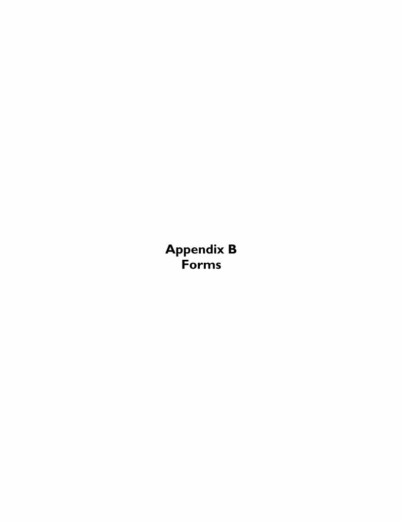
Commissioning Guideline Region of Niagara
Rev 00 Appendix B
Page B-1
Commissioning Guideline Region of Niagara
Rev 00 Appendix B
Page B-2
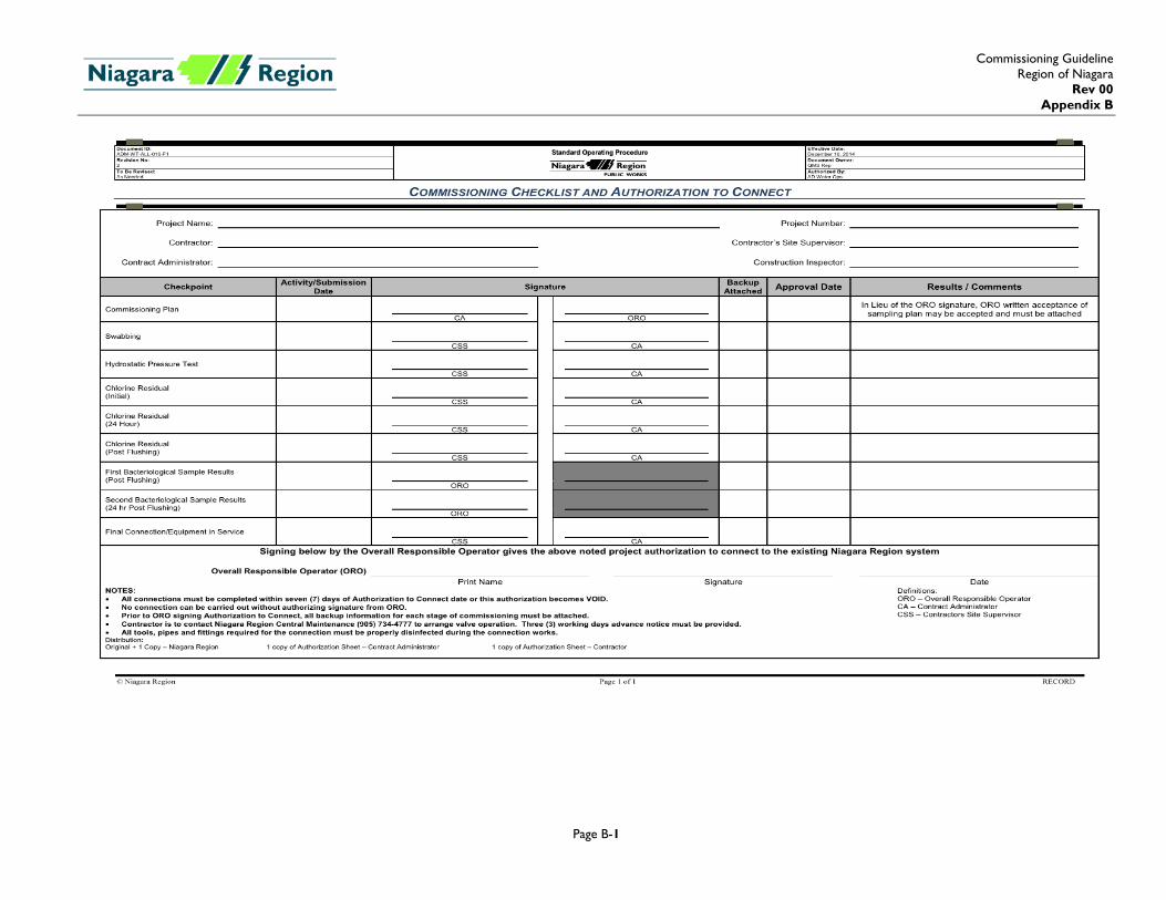
Form G-01
Safety Compliance Form Contract Title Contract No. Date Test Duration Test 1. In order to ensure the safety of personnel during testing, Commissioning Manager(s) need to acknowledge, initial, and date this announcement.
Construction and Testing Safety rules must be followed. 2. Commissioning Manager(s) shall relay the announcement to all involved manufacturer representatives and sub-contractors, and ensure that they
acknowledge the test and safety rules. 3. Commissioning Manager is to complete this form prior to proceeding with testing.
Test Reference Description
Acknowledgement Comments Company/
Discipline Representative Initial Date
Commissioning Guideline Region of Niagara
Rev 00 Appendix B
Page B-3
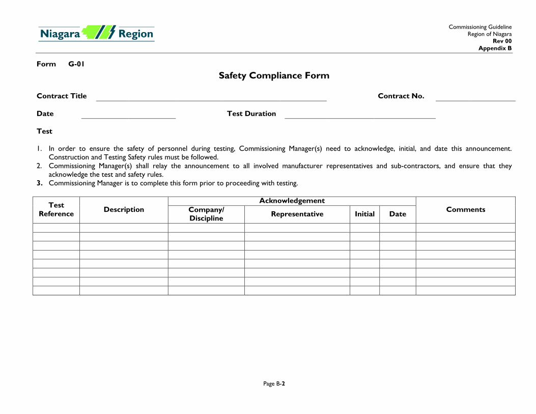
Form G-02
Notification of Testing Contract Title Contract No.
The following test is scheduled as shown
System/Test Test Date Test Duration
Organization Subcontractor/ Supplier Details Name Attending Comments Initial
Commissioning Guideline Region of Niagara
Rev 00 Appendix B
Page B-4
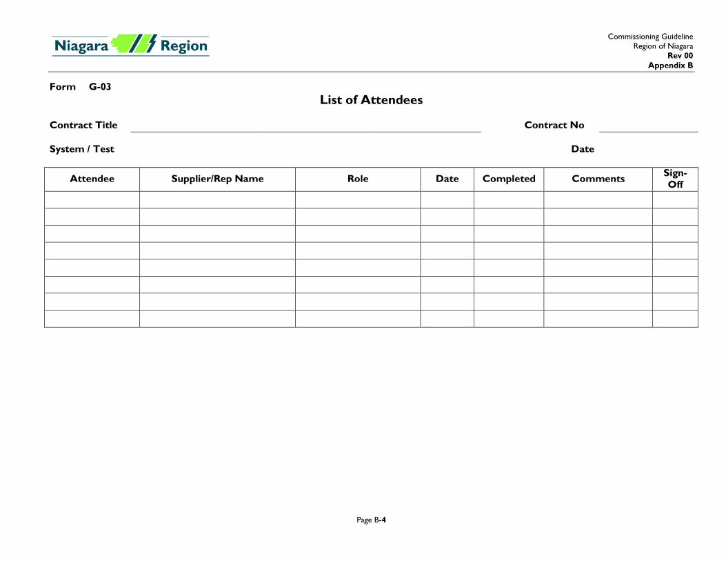
Form G-03 List of Attendees
Contract Title Contract No System / Test Date
Attendee Supplier/Rep Name Role Date Completed Comments Sign-Off
Commissioning Guideline Region of Niagara
Rev 00 Appendix B
Page B-5
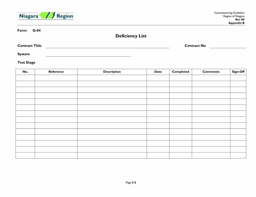
Form G-04
Deficiency List Contract Title Contract No System Test Stage
No. Reference Description Date Completed Comments Sign-Off
Commissioning Guideline Region of Niagara
Rev 00 Appendix B
Page B-6
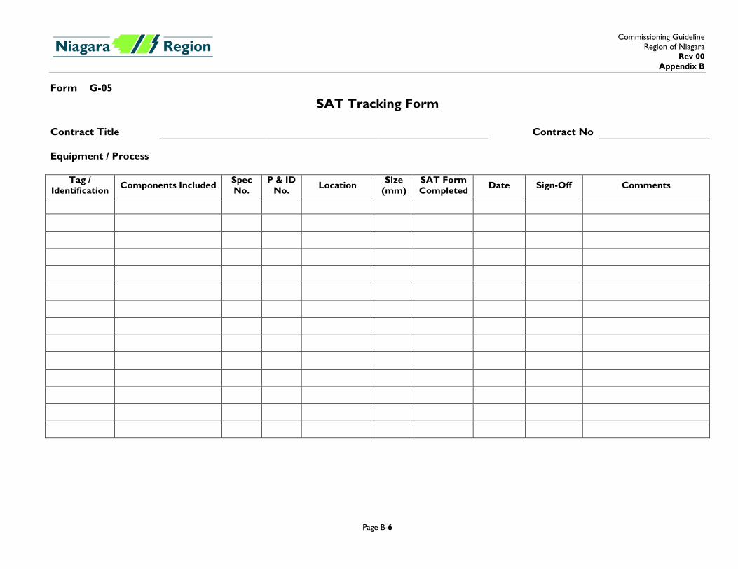
Form G-05
SAT Tracking Form Contract Title Contract No Equipment / Process
Tag / Identification Components Included Spec
No. P & ID
No. Location Size (mm)
SAT Form Completed Date Sign-Off Comments

Commissioning Guideline Region of Niagara
Rev 00 Appendix B
Page B-7
Form G-06
Equipment / Process Training Form Contract Title Contract No Date In-class � On-site �
Equipment / Process
1. 10. 2. 11. 3. 12. 4. 13. 5. 14. 6. 15. 7. 16. 8. 17. 9. 18.
Name (Print) Signature W & WW Section
Contractor’s Commissioning Manager
Signature
Contractor Administrator’s Commissioning Manager
Signature
Commissioning Guideline Region of Niagara
Rev 00 Appendix B
Page B-8
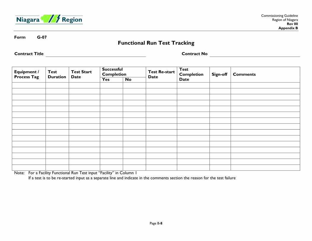
Form G-07 Functional Run Test Tracking
Contract Title Contract No
Equipment / Process Tag
Test Duration
Test Start Date
Successful Completion Test Re-start
Date
Test Completion Date
Sign-off Comments Yes No
Note: For a Facility Functional Run Test input “Facility” in Column 1 If a test is to be re-started input as a separate line and indicate in the comments section the reason for the test failure
Commissioning Guideline Region of Niagara
Rev 00 Appendix B
Page B-9
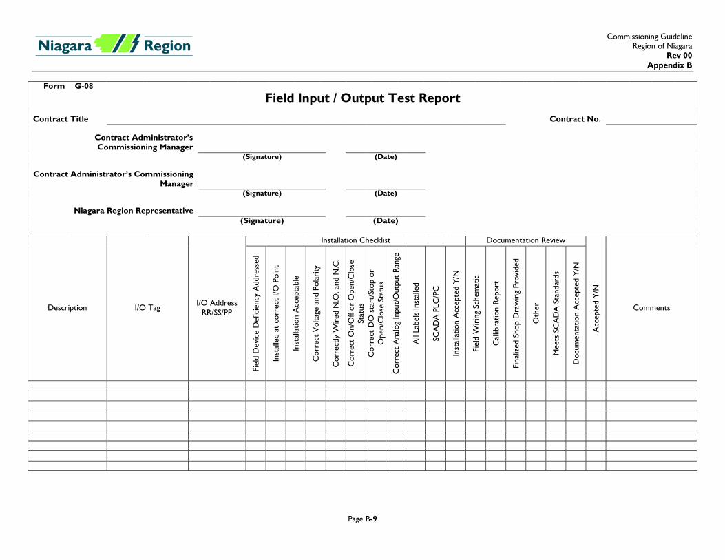
Form G-08
Field Input / Output Test Report Contract Title Contract No.
Contract Administrator’s Commissioning Manager
(Signature) (Date) Contract Administrator’s Commissioning
Manager
(Signature) (Date)
Niagara Region Representative (Signature) (Date)
Description I/O Tag I/O Address RR/SS/PP
Installation Checklist Documentation Review
Acc
epte
d Y/
N
Comments
Fiel
d D
evic
e D
efic
ienc
y A
ddre
ssed
Inst
alle
d at
cor
rect
I/O
Poi
nt
Inst
alla
tion
Acc
epta
ble
Cor
rect
Vol
tage
and
Pol
arity
Cor
rect
ly W
ired
N.O
. and
N.C
.
Cor
rect
On/
Off
or O
pen/
Clo
se
Stat
us
Cor
rect
DO
sta
rt/S
top
or
Ope
n/C
lose
Sta
tus
Cor
rect
Ana
log
Inpu
t/O
utpu
t Ra
nge
All
Labe
ls In
stal
led
SCA
DA
PLC
/PC
Inst
alla
tion
Acc
epte
d Y/
N
Fiel
d W
irin
g Sc
hem
atic
Cal
libra
tion
Repo
rt
Fina
lized
Sho
p D
raw
ing
Prov
ided
Oth
er
Mee
ts S
CA
DA
Sta
ndar
ds
Doc
umen
tatio
n A
ccep
ted
Y/N
Commissioning Guideline Region of Niagara
Rev 00 Appendix B
Page B-10
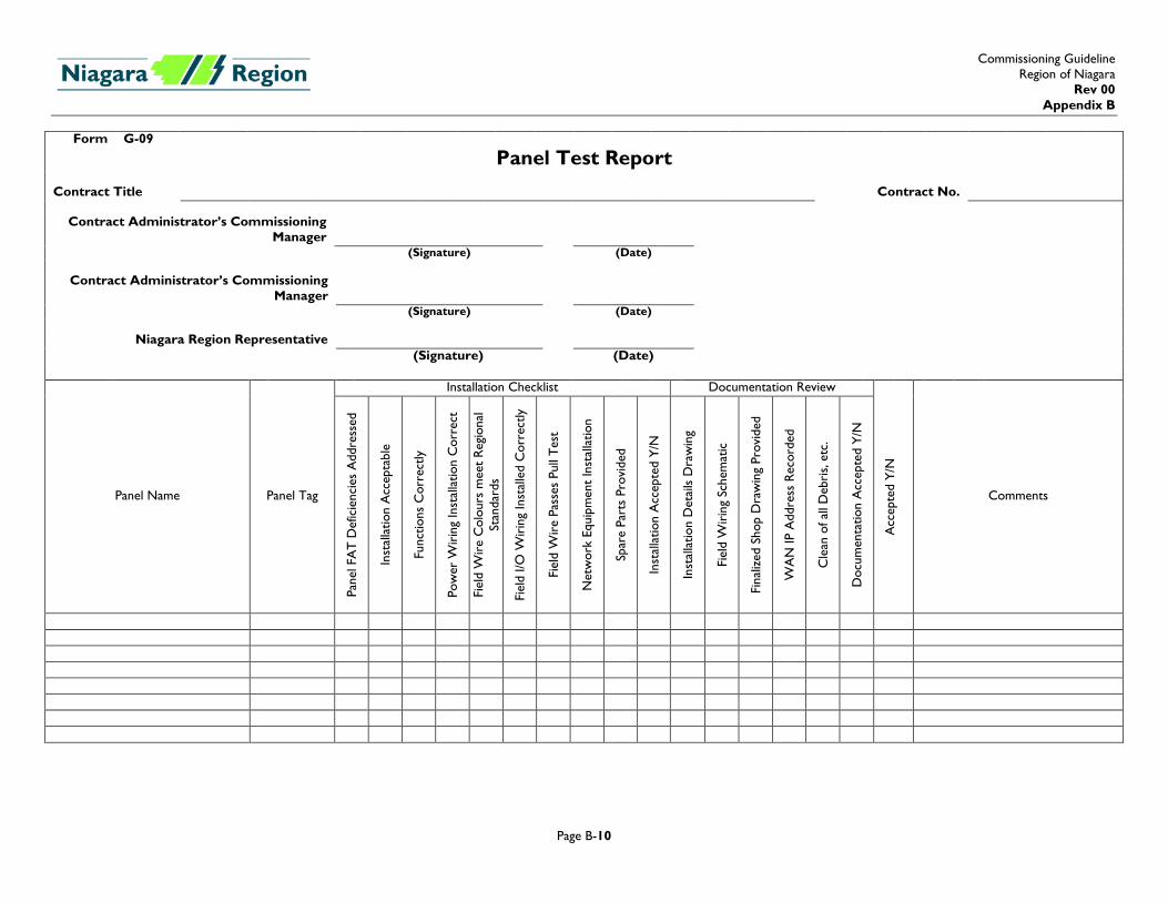
Form G-09
Panel Test Report Contract Title Contract No.
Contract Administrator’s Commissioning Manager
(Signature) (Date)
Contract Administrator’s Commissioning Manager
(Signature) (Date)
Niagara Region Representative (Signature) (Date)
Panel Name Panel Tag
Installation Checklist Documentation Review
Acc
epte
d Y/
N
Comments
Pane
l FA
T D
efic
ienc
ies
Add
ress
ed
Inst
alla
tion
Acc
epta
ble
Func
tions
Cor
rect
ly
Pow
er W
irin
g In
stal
latio
n C
orre
ct
Fiel
d W
ire
Col
ours
mee
t Re
gion
al
Stan
dard
s
Fiel
d I/O
Wir
ing
Inst
alle
d C
orre
ctly
Fiel
d W
ire
Pass
es P
ull T
est
Net
wor
k Eq
uipm
ent
Inst
alla
tion
Spar
e Pa
rts
Prov
ided
Inst
alla
tion
Acc
epte
d Y/
N
Inst
alla
tion
Det
ails
Dra
win
g
Fiel
d W
irin
g Sc
hem
atic
Fina
lized
Sho
p D
raw
ing
Prov
ided
WA
N IP
Add
ress
Rec
orde
d
Cle
an o
f all
Deb
ris,
etc.
Doc
umen
tatio
n A
ccep
ted
Y/N
Commissioning Guideline Region of Niagara
Rev 00 Appendix B
Page B-11
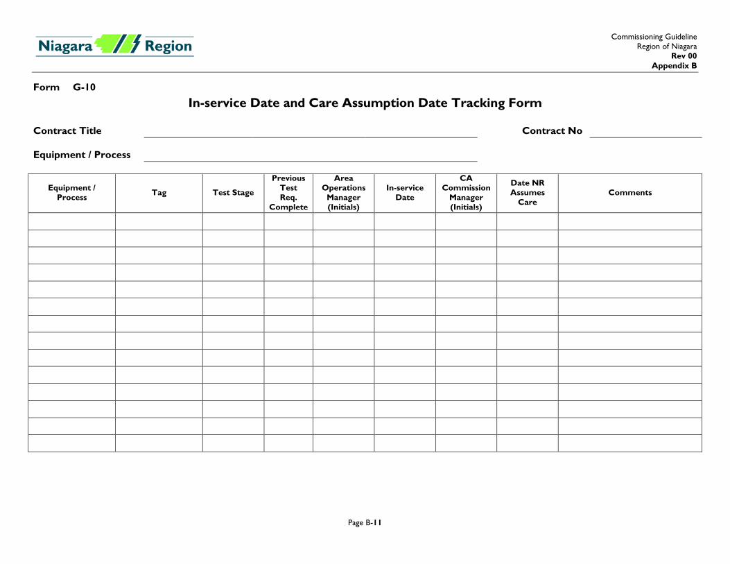
Form G-10
In-service Date and Care Assumption Date Tracking Form Contract Title Contract No Equipment / Process
Equipment / Process Tag Test Stage
Previous Test Req.
Complete
Area Operations
Manager (Initials)
In-service Date
CA Commission
Manager (Initials)
Date NR Assumes
Care Comments
Commissioning Guideline Region of Niagara
Rev 00 Appendix B
Page B-12
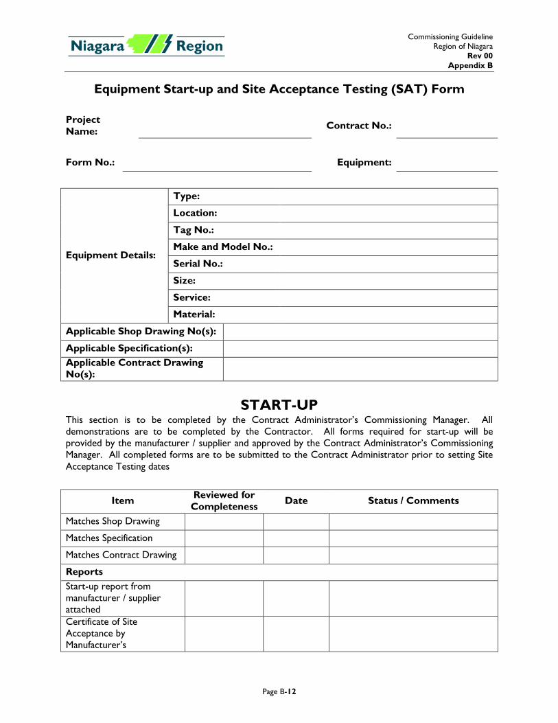
Equipment Start-up and Site Acceptance Testing (SAT) Form Project Name: Contract No.:
Form No.: Equipment:
Equipment Details:
Type:
Location:
Tag No.:
Make and Model No.:
Serial No.:
Size:
Service:
Material:
Applicable Shop Drawing No(s):
Applicable Specification(s): Applicable Contract Drawing No(s):
START-UP This section is to be completed by the Contract Administrator’s Commissioning Manager. All demonstrations are to be completed by the Contractor. All forms required for start-up will be provided by the manufacturer / supplier and approved by the Contract Administrator’s Commissioning Manager. All completed forms are to be submitted to the Contract Administrator prior to setting Site Acceptance Testing dates
Item Reviewed for Completeness Date Status / Comments
Matches Shop Drawing
Matches Specification
Matches Contract Drawing
Reports Start-up report from manufacturer / supplier attached
Certificate of Site Acceptance by Manufacturer’s
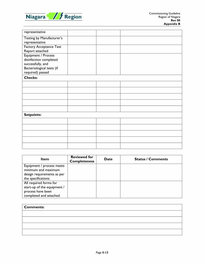
Commissioning Guideline Region of Niagara
Rev 00 Appendix B
Page B-13
representative
Testing by Manufacturer’s representative
Factory Acceptance Test Report attached
Equipment / Process disinfection completed successfully, and Bacteriological tests (if required) passed
Checks:
Setpoints:
Item Reviewed for Completeness Date Status / Comments
Equipment / process meets minimum and maximum design requirements as per the specifications
All required forms for start-up of the equipment / process have been completed and attached
Comments:
Commissioning Guideline Region of Niagara
Rev 00 Appendix B
Page B-14
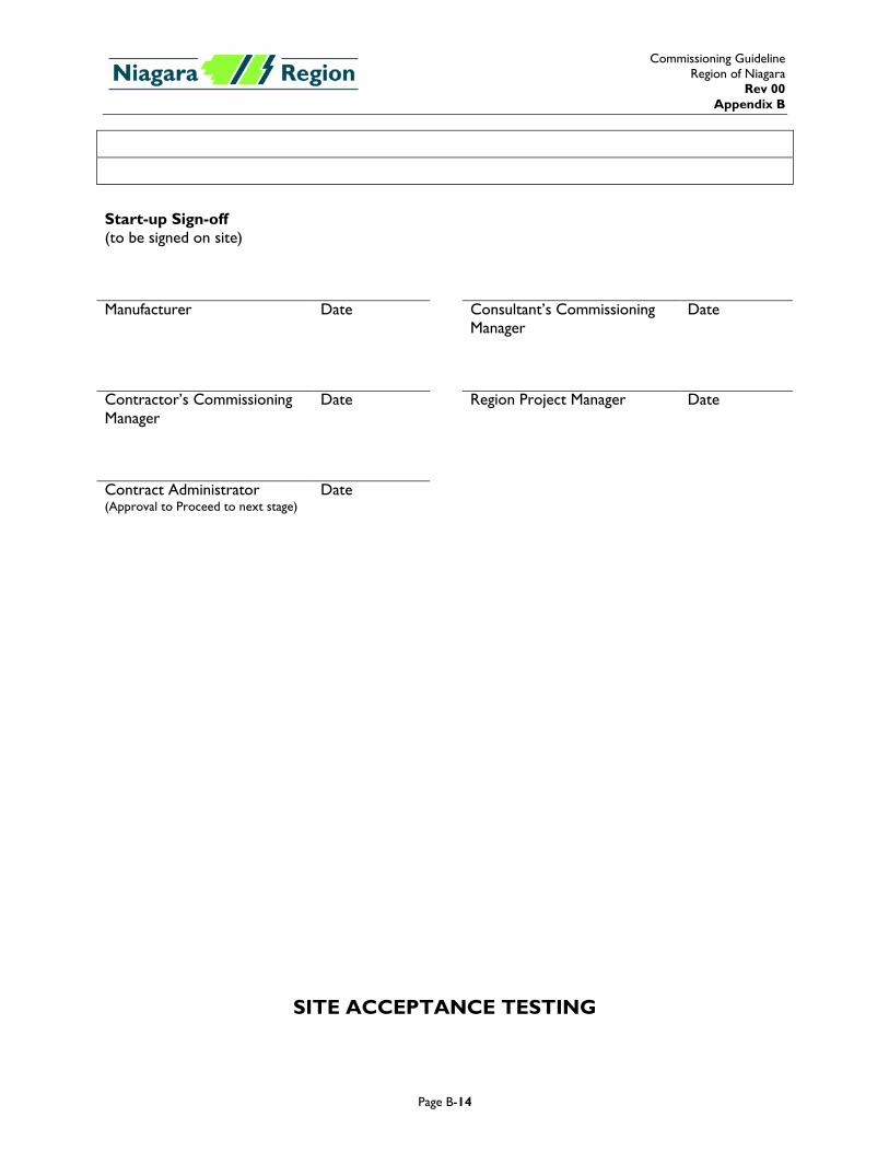
Start-up Sign-off (to be signed on site)
Manufacturer Date Consultant’s Commissioning
Manager Date
Contractor’s Commissioning Manager
Date Region Project Manager Date
Contract Administrator (Approval to Proceed to next stage)
Date
SITE ACCEPTANCE TESTING
Commissioning Guideline Region of Niagara
Rev 00 Appendix B
Page B-15
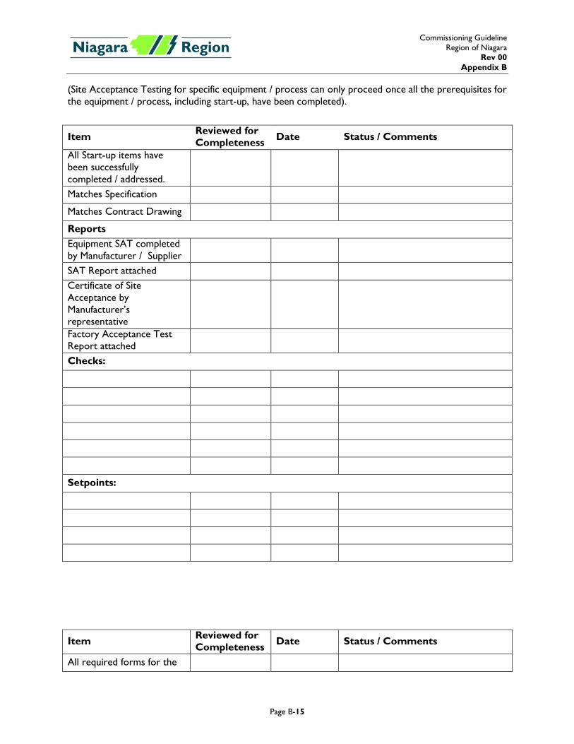
(Site Acceptance Testing for specific equipment / process can only proceed once all the prerequisites for the equipment / process, including start-up, have been completed).
Item Reviewed for Completeness Date Status / Comments
All Start-up items have been successfully completed / addressed.
Matches Specification
Matches Contract Drawing
Reports Equipment SAT completed by Manufacturer / Supplier
SAT Report attached Certificate of Site Acceptance by Manufacturer’s representative
Factory Acceptance Test Report attached
Checks:
Setpoints:
Item Reviewed for Completeness Date Status / Comments
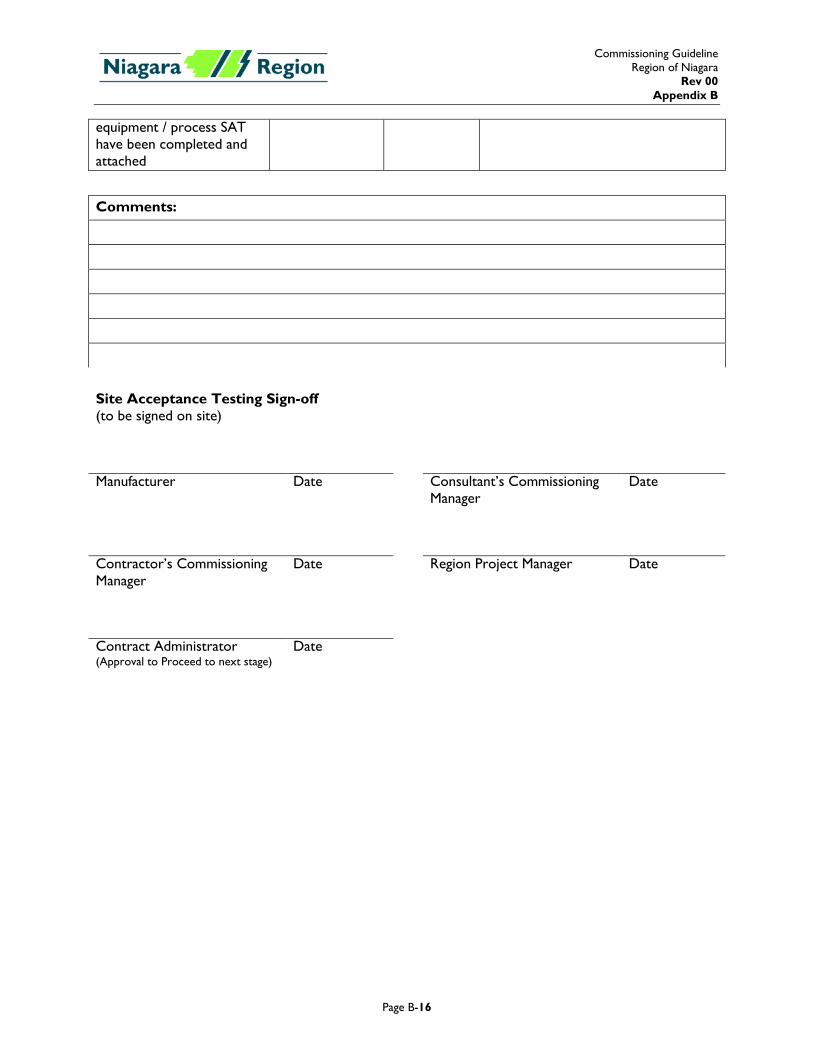
All required forms for the
Commissioning Guideline Region of Niagara
Rev 00 Appendix B
Page B-16
equipment / process SAT have been completed and attached
Comments:
Site Acceptance Testing Sign-off (to be signed on site)
Manufacturer Date Consultant’s Commissioning
Manager Date
Contractor’s Commissioning Manager
Date Region Project Manager Date
Contract Administrator (Approval to Proceed to next stage)
Date
Commissioning Guideline Region of Niagara
Rev 00 Appendix B
Page B-17
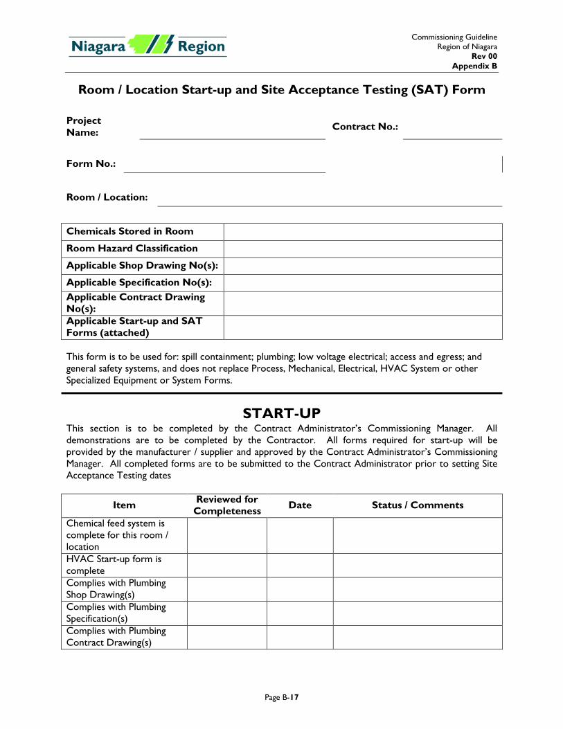
Room / Location Start-up and Site Acceptance Testing (SAT) Form Project Name: Contract No.:
Form No.:
Room / Location:
Chemicals Stored in Room
Room Hazard Classification
Applicable Shop Drawing No(s):
Applicable Specification No(s): Applicable Contract Drawing No(s):
Applicable Start-up and SAT Forms (attached)
This form is to be used for: spill containment; plumbing; low voltage electrical; access and egress; and general safety systems, and does not replace Process, Mechanical, Electrical, HVAC System or other Specialized Equipment or System Forms.
START-UP This section is to be completed by the Contract Administrator’s Commissioning Manager. All demonstrations are to be completed by the Contractor. All forms required for start-up will be provided by the manufacturer / supplier and approved by the Contract Administrator’s Commissioning Manager. All completed forms are to be submitted to the Contract Administrator prior to setting Site Acceptance Testing dates
Item Reviewed for Completeness Date Status / Comments
Chemical feed system is complete for this room / location
HVAC Start-up form is complete
Complies with Plumbing Shop Drawing(s)
Complies with Plumbing Specification(s)
Complies with Plumbing Contract Drawing(s)
Commissioning Guideline Region of Niagara
Rev 00 Appendix B
Page B-18
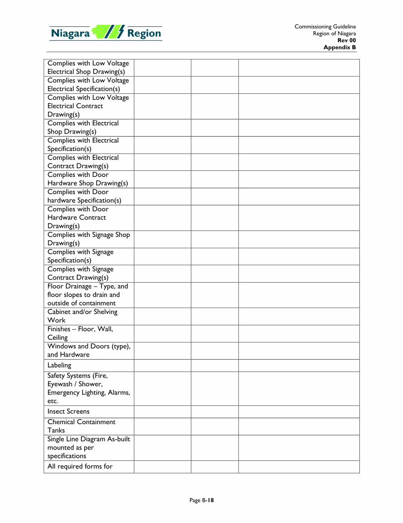
Complies with Low Voltage Electrical Shop Drawing(s)
Complies with Low Voltage Electrical Specification(s)
Complies with Low Voltage Electrical Contract Drawing(s)
Complies with Electrical Shop Drawing(s)
Complies with Electrical Specification(s)
Complies with Electrical Contract Drawing(s)
Complies with Door Hardware Shop Drawing(s)
Complies with Door hardware Specification(s)
Complies with Door Hardware Contract Drawing(s)
Complies with Signage Shop Drawing(s)
Complies with Signage Specification(s)
Complies with Signage Contract Drawing(s)
Floor Drainage – Type, and floor slopes to drain and outside of containment
Cabinet and/or Shelving Work
Finishes – Floor, Wall, Ceiling
Windows and Doors (type), and Hardware
Labeling Safety Systems (Fire, Eyewash / Shower, Emergency Lighting, Alarms, etc.
Insect Screens Chemical Containment Tanks
Single Line Diagram As-built mounted as per specifications
All required forms for
Commissioning Guideline Region of Niagara
Rev 00 Appendix B
Page B-19
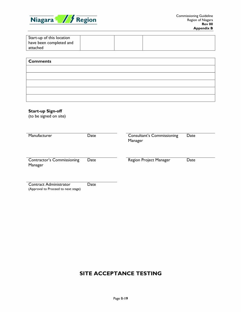
Start-up of this location have been completed and attached
Comments
Start-up Sign-off (to be signed on site)
Manufacturer Date Consultant’s Commissioning
Manager Date
Contractor’s Commissioning Manager
Date Region Project Manager Date
Contract Administrator (Approval to Proceed to next stage)
Date
SITE ACCEPTANCE TESTING
Commissioning Guideline Region of Niagara
Rev 00 Appendix B
Page B-20
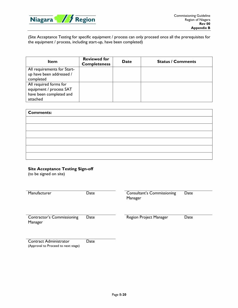
(Site Acceptance Testing for specific equipment / process can only proceed once all the prerequisites for the equipment / process, including start-up, have been completed)
Item Reviewed for Completeness Date Status / Comments
All requirements for Start-up have been addressed / completed
All required forms for equipment / process SAT have been completed and attached
Comments:
Site Acceptance Testing Sign-off (to be signed on site)
Manufacturer Date Consultant’s Commissioning
Manager Date
Contractor’s Commissioning Manager
Date Region Project Manager Date
Contract Administrator (Approval to Proceed to next stage)
Date
Commissioning Guideline Region of Niagara
Rev 00 Appendix B
Page B-21
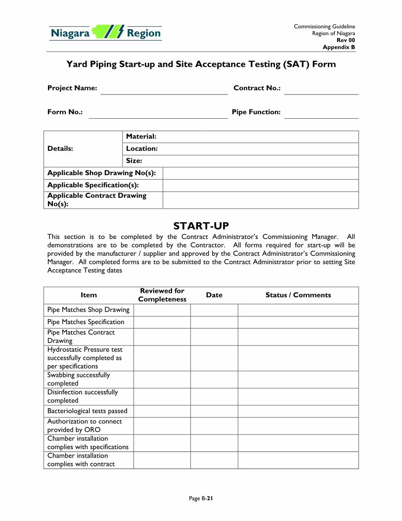
Yard Piping Start-up and Site Acceptance Testing (SAT) Form
Project Name: Contract No.:
Form No.: Pipe Function:
Details:
Material:
Location:
Size:
Applicable Shop Drawing No(s):
Applicable Specification(s): Applicable Contract Drawing No(s):
START-UP This section is to be completed by the Contract Administrator’s Commissioning Manager. All demonstrations are to be completed by the Contractor. All forms required for start-up will be provided by the manufacturer / supplier and approved by the Contract Administrator’s Commissioning Manager. All completed forms are to be submitted to the Contract Administrator prior to setting Site Acceptance Testing dates
Item Reviewed for Completeness Date Status / Comments
Pipe Matches Shop Drawing
Pipe Matches Specification Pipe Matches Contract Drawing
Hydrostatic Pressure test successfully completed as per specifications
Swabbing successfully completed
Disinfection successfully completed
Bacteriological tests passed Authorization to connect provided by ORO
Chamber installation complies with specifications
Chamber installation complies with contract
Commissioning Guideline Region of Niagara
Rev 00 Appendix B
Page B-22
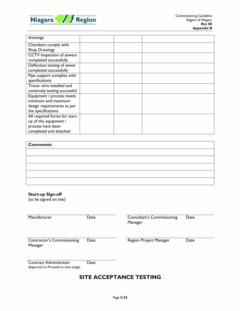
drawings
Chambers comply with Shop Drawings
CCTV Inspection of sewers completed successfully
Deflection testing of sewer completed successfully
Pipe support complies with specifications
Tracer wire installed and continuity testing successful
Equipment / process meets minimum and maximum design requirements as per the specifications
All required forms for start-up of the equipment / process have been completed and attached
Comments:
Start-up Sign-off (to be signed on site)
Manufacturer Date Consultant’s Commissioning
Manager Date
Contractor’s Commissioning Manager
Date Region Project Manager Date
Contract Administrator (Approval to Proceed to next stage)
Date
SITE ACCEPTANCE TESTING
Commissioning Guideline Region of Niagara
Rev 00 Appendix B
Page B-23
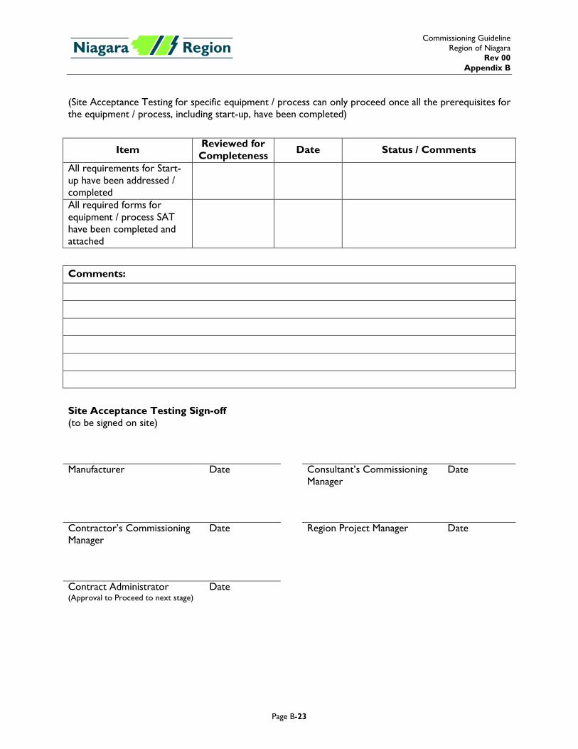
(Site Acceptance Testing for specific equipment / process can only proceed once all the prerequisites for the equipment / process, including start-up, have been completed)
Item Reviewed for Completeness Date Status / Comments
All requirements for Start-up have been addressed / completed
All required forms for equipment / process SAT have been completed and attached
Comments:
Site Acceptance Testing Sign-off (to be signed on site)
Manufacturer Date Consultant’s Commissioning
Manager Date
Contractor’s Commissioning Manager
Date Region Project Manager Date
Contract Administrator (Approval to Proceed to next stage)
Date
Regional Municipality of Niagara Division 13
South Side Low Lift SPS Upgrades PLC Control Panels and Communication
Contract RN #17-04 Section 13911
Hatch Ltd. Page 1 of 16
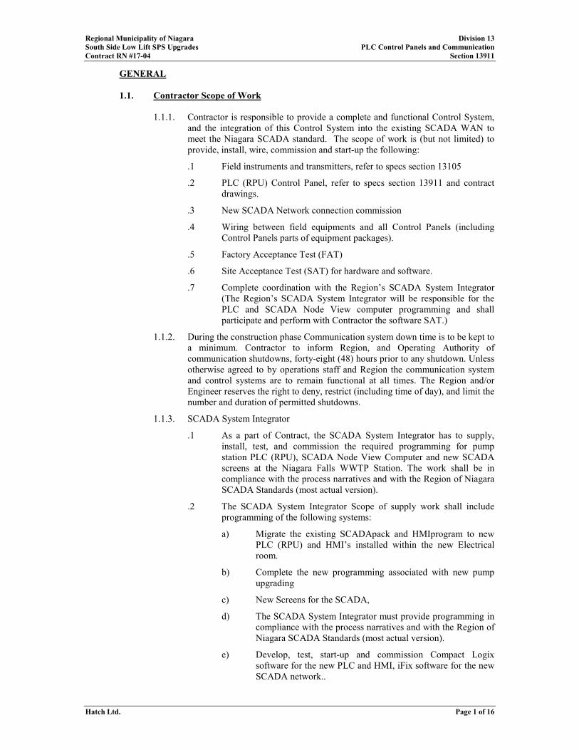
GENERAL
1.1. Contractor Scope of Work
1.1.1. Contractor is responsible to provide a complete and functional Control System,
and the integration of this Control System into the existing SCADA WAN to
meet the Niagara SCADA standard. The scope of work is (but not limited) to
provide, install, wire, commission and start-up the following:
.1 Field instruments and transmitters, refer to specs section 13105
.2 PLC (RPU) Control Panel, refer to specs section 13911 and contract
drawings.
.3 New SCADA Network connection commission
.4 Wiring between field equipments and all Control Panels (including
Control Panels parts of equipment packages).
.5 Factory Acceptance Test (FAT)
.6 Site Acceptance Test (SAT) for hardware and software.
.7 Complete coordination with the Region’s SCADA System Integrator
(The Region’s SCADA System Integrator will be responsible for the
PLC and SCADA Node View computer programming and shall
participate and perform with Contractor the software SAT.)
1.1.2. During the construction phase Communication system down time is to be kept to
a minimum. Contractor to inform Region, and Operating Authority of
communication shutdowns, forty-eight (48) hours prior to any shutdown. Unless
otherwise agreed to by operations staff and Region the communication system
and control systems are to remain functional at all times. The Region and/or
Engineer reserves the right to deny, restrict (including time of day), and limit the
number and duration of permitted shutdowns.
1.1.3. SCADA System Integrator
.1 As a part of Contract, the SCADA System Integrator has to supply,
install, test, and commission the required programming for pump
station PLC (RPU), SCADA Node View Computer and new SCADA
screens at the Niagara Falls WWTP Station. The work shall be in
compliance with the process narratives and with the Region of Niagara
SCADA Standards (most actual version).
.2 The SCADA System Integrator Scope of supply work shall include
programming of the following systems:
a) Migrate the existing SCADApack and HMIprogram to new
PLC (RPU) and HMI’s installed within the new Electrical
room.
b) Complete the new programming associated with new pump
upgrading
c) New Screens for the SCADA,
d) The SCADA System Integrator must provide programming in
compliance with the process narratives and with the Region of
Niagara SCADA Standards (most actual version).
e) Develop, test, start-up and commission Compact Logix
software for the new PLC and HMI, iFix software for the new
SCADA network..
Regional Municipality of Niagara Division 13
South Side Low Lift SPS Upgrades PLC Control Panels and Communication
Contract RN #17-04 Section 13911
Hatch Ltd. Page 2 of 16
f) Develop, test start-up and commission the HMI software for
the pump station and SCADA, including alarming, historical
data collection and graphical displays.
g) PLC and SCADA Screens FAT testing.
h) PLC and SCADA Screens SAT testing.
i) Provide complete documentation (SCADA manual) at
completion of the project.
j) Supply twelve (12) hours of SCADA system training for the
Region staff.
k) Supply SCADA operation manuals (Qty.: 6), containing the
following sections:
1. Network Diagram
2. Process Control Narrative. This document will be
provided to Contractor by SCADA System
Integrator, end of the commissioning and start-up.
3. SCADA Node View Computer Operation including
screen shots
l) Provide and update the process control narrative in co-
operation with Consultant and the Region.
m) All other items remain the responsibility of the Contractor.
.3 Region’s SCADA System Integrator:
a) Hatch Ltd.
.4 All programs and applications created under the WWTP upgrades will
be owned by the Region of Niagara, with the following items:
a) The SCADA System Integrator shall not affix any copyrights
to any works. All licenses for software and applications to be
registered to the Region of Niagara.
b) The SCADA System Integrator must use the tools inherently
provided within the SCADA network, HMI and Compact
Logix programming software.
c) Programming to be based on functional block techniques,
ladder logic programming will not be accepted.
d) All configuration files and raw source files must remain intact.
e) The SCADA network PLC’s, HMI,s and Compact Logix
programs and applications must remain 100% editable by
Region staff using the programs native programming tools at
the conclusion of the contract.
f) Failure to meet all of the above requirements will result in
Substantial Completion being withheld.
1.2. Shop Drawings
1.2.1. Submit shop drawings within two (2) weeks of award of contract in accordance
with Division 16 and Contract Specifications.
1.2.2. Include:
Regional Municipality of Niagara Division 13
South Side Low Lift SPS Upgrades PLC Control Panels and Communication
Contract RN #17-04 Section 13911
Hatch Ltd. Page 3 of 16
.1 Schematic
.2 Wiring
.3 Interconnection Diagrams
.4 Network Architecture
a) Indicate patch panels, connect blocks, jacks, network cabling
and patch cords.
b) All communication equipment. Indicate models and part
numbers.
.5 Network Integration Plan
1.2.3. Additional Requirements:
.1 For devices containing dip switches, jumpers or programming keypads:
a) Functional description.
b) Performance data.
c) Physical, electrical and environmental requirements.
d) Location drawing.
e) Equipment descriptive literature.
f) Wiring details.
.2 For programmable equipment, communication links and networks,
submit bill of materials. Include in bill of materials hardware
documentation.
a) For hardware items include and clearly identify: Description,
make, model, part number and serial number.
b) For documentation include: Title and publisher for each item.
.3 For Programmable Equipment Hardware:
a) Product description for each item including:
1. Wiring and installation instructions.
2. Functional description.
3. Performance data.
4. Physical, electrical and environmental requirements.
5. Adapters and controllers.
b) Equipment layout drawings showing location of hardware,
boards, jacks, cables and terminals.
c) Related field tag numbers and wire numbers and module tag
assignment, to follow the Region of Niagara Tagging
standards.
d) Location and identifier and pin assignment of plugs, jacks, and
cables.
e) Switch settings and addresses, firmware.
f) Interconnection Diagrams including wiring, cables, jacks
between internal and external components, power supplies,
processors, communications modules, racks, I/O modules and
Regional Municipality of Niagara Division 13
South Side Low Lift SPS Upgrades PLC Control Panels and Communication
Contract RN #17-04 Section 13911
Hatch Ltd. Page 4 of 16
peripherals. Label terminals, jacks and pins. Show settings for
jumpers and switches. Show address for each hardware
module and point.
1.3. Related Work
1.3.1. Divisions 11 and 16 of the Contract Specifications.
1.4. Warranty
1.4.1. During the warranty period, as specified under contract documents, hardware
service shall be provided by factory trained service representative who shall be
on-site within 8 hours of a service request, 24 hours/day, 7 days/week, including
weekends and holidays.
1.4.2. The service representative shall be equipped with all necessary tools, testing
equipment, spare parts, and expertise to perform the service in one visit.
1.4.3. For each service call submit a report giving the following information:
.1 Part numbers, description for items replaced.
.2 Revised hardcopy listings of program or date changes.
.3 Hours worked by maintenance personnel, itemized by Specification
item number.
.4 Reason for the service call, and whether preventative, unscheduled or
corrective maintenance was carried out.
.5 Name of Region’s technician present during repairs.
.6 Explanation of the problem and solutions to the Region’s technician(s).
.7 Description of problem as discovered on arrival at site and itemized
report of activities performed to isolate and correct problem.
.8 Identification of any required actions to prevent similar future
occurrence.
.9 Name of attending maintenance representative, time of call and time of
arrival on site.
1.4.4. A single contact point shall be provided for all hardware such that the Region
need only call a single phone number irrespective of which hardware had failed.
1.4.5. The Region’s technician(s) may be present during repairs. Explain the problem
and solutions to the Region’s technician(s).
1.4.6. Free telephone support shall be provided for the total system and all parts
thereof during the warranty period
1.4.7. Spare Parts / Firmware & Software Upgrades:
.1. The Supplier should have access to a dedicated spare parts inventory
for each component provided. Parts shall be available within 4 hours of
a service parts request, 24 hours/day 7 days/week.
.2. Include key spare parts which are not normally available immediately
from stock, in the Recommended Spare Parts List.
.3. Provide, install, test and place in operation any firmware upgrades
issued by manufacturers to address shortcomings in delivered products
during the warranty period at no cost to the Region.
Regional Municipality of Niagara Division 13
South Side Low Lift SPS Upgrades PLC Control Panels and Communication
Contract RN #17-04 Section 13911
Hatch Ltd. Page 5 of 16
.4. Advise the Region/Engineer of software upgrades and new versions
which become available that would benefit or enhance the installed
system.
2. PRODUCTS
2.1. PLC Control Panel
2.1.1. Supply, install, test, and commission fully functional Allen Bradley Compact
Logix process automation controller, associated I/O modules and ancillary
equipment. The SCADA upgrade programming to be done by the SCADA
System Integrator (named by Consultant) under a separate contract..
2.1.2. Allow a minimum of four (8) weeks for programming of the Compact Logix
PLC, HMI and SCADA screens, following hardware delivery by the contractor.
2.1.3. Provide all interconnecting cables between PLC and other networking
components as required for a complete system.
2.1.4. Provide all RS-232, RS-485, and Ethernet cables, and any other required
communication cable as required for a complete network.
2.1.5. Allen Bradley COMPACT LOGIX components (minimum quantities), and
communication equipment.
.1 Contractor is responsible for verifying the quantities contained in the
following table, and for all additional components, cables, etc. required
to complete the work as defined in the specifications and on the
drawings. Quantities listed in a list/table (as the above sample) to
include all COMPACT LOGIX components to be installed in this
application.
.2 Allow 20% spare I/O points for each signal type. Unless otherwise
noted in the Contract Drawings the PLC I/O rack shall be 80% full,
leaving 20% spare.
.3 If the second additional bank of I/O is required, provide an other 1769-
PA4 power supply and the corresponding Expansion Cable and End
Cap.
.4 All hardware not specifically identified in Section 2.1 remains the
responsibility of the contractor, including but not limited to network
and interconnecting cabling, network jacks, patch cords, couplers,
adapters to provide a fully functional control system.
2.2. Control Devices
2.2.1. AC Control Relays (Qty.: As Required)
.1 Universal pole type: electrically held with 3 poles, convertible from NO
to NC by changing wiring connections. Coil rating: 120 V, 3 VA.
Contact rating: 120 V, 10 A.
.2 Manufacturers:
a) Allen-Bradley 700HA,
b) Omron
c) Potter & Brumfield
d) Square D.
2.2.2. Solid State Timing Relays (Qty: As Required)
Regional Municipality of Niagara Division 13
South Side Low Lift SPS Upgrades PLC Control Panels and Communication
Contract RN #17-04 Section 13911
Hatch Ltd. Page 6 of 16
.1 Construction: AC operated electronic timing relay with solid-state
timing circuit to operate output contact. Timing circuit and output
contact completely encapsulated to protect against vibration, humidity
and atmospheric contaminants.
.2 Operation: on-delay or off-delay, as indicated on drawings.
.3 Potentiometer: self contained to provide time interval adjustment.
.4 Supply Voltage: 120 Vac, 60 Hz.
.5 Temperature range: minus 20º C to 60º C.
.6 Output contact rating: maximum Voltage 120 VAC or dc. Current:
EEMAC B300.
.7 Timing ranges: minimum 1.0 s, maximum 60 s, unless otherwise
specified.
.8 Manufacturer:
a) Allen-Bradley 700HA,
b) Omron
c) Potter & Brumfield
d) Square D.
2.2.3. Interposing PLC Panel Relays (Qty: As Required)
.1 Entrelec. Din-Rail mounted.
120 VAC relays
a) Rated Voltage: 120VAC.
b) Power: 1VA.
c) Rated Current: 9mA.
d) Drop-out Voltage: 20VAC.
e) RB121AR2, P/N: 010 168.01.
24VDC Relays:
f) Rated Voltage: 24VDC.
g) Power: 0.31W.
h) Rated Current: 13mA.
i) Drop-out Voltage: 2.4VDC.
j) RB122, P/N: 010 159.07
2.2.4. Pushbuttons (Qty.: As Required)
.1 Oil tight. Operator extend type 30mm diameter. Black with NO and
NC 120 V contacts rated at 720 VA ac, labels as indicated. Stop
pushbuttons coloured red. Start pushbuttons coloured green. Reset
buttons coloured black.
.2 Manufacturers:
a) Allen-Bradley 800T,
b) Cutler Hammer,
c) Square D.
Regional Municipality of Niagara Division 13
South Side Low Lift SPS Upgrades PLC Control Panels and Communication
Contract RN #17-04 Section 13911
Hatch Ltd. Page 7 of 16
2.2.5. Selector Switches (Qty: As Required)
.1 Maintained unless otherwise indicated, labeled as indicated, heavy
duty, 30mm diameter oil-tight standard operators, contact arrangement
as indicated, rated 120 V, 720 VA ac.
.2 Provide number of positions as shown on the drawings.
.3 HAND-OFF-AUTO switches to be break-before-make.
.4 LOCAL-REMOTE switches to be make-before-break.
.5 Allen-Bradley 800T, Cutler Hammer, Square D.
2.2.6. Indicating Lights (Qty: As Required)
.1 Oil-tight, transformer type, 30mm diameter, lens colour: as indicated,
supply Voltage: 120V, labels as indicated. Push-to-test function on all
pilot lights. Provide LED-style lamps for CP-01.
.2 Manufacturers:
a) Allen-Bradley 800T,
b) Cutler Hammer,
c) Square D.
2.3. Control and Relay Panels
2.3.1. Manufactured Units.
.1 Control panels: Complete working system with instruments, meters,
indication lights, alarm annunicators, protection and control relays,
programmable logic controllers, transducers, contractors, switches,
auxiliary devices and similar items.
.2 Arrangement of instruments and devices (face-mounted as well as rear-
of-panel mounted): Allow sufficient access for maintenance.
.3 Mounting Height: Indicating devices, controls and instruments between
1000 mm and 2000 mm above finished floor. Allow for housekeeping
pads, pedestals and similar items.
.4 Side or back face mounted devices: On removable backplate. Direct
mounted devices will not be accepted.
.5 Nameplates: Removable, lamacoid, to identify panel and equipment
function, letters minimum 6 mm, fasten with stainless steel screws.
Grind screws flush on inside of panel so no sharp edges protrude.
.6 Supply panels complete with wiring and header piping connections.
2.3.2. Enclosure
.1 Dry areas: Rigid, dead front, 2 mm steel sheet, NEMA/EEMAC 12
unless otherwise noted.
.2 Wet and damp and process areas: Rigid, dead front, 2 mm, 304
stainless steel sheet, NEMA/EEMC 4X, with stainless steel hardware.
.3 Corrosive areas: Rigid, dead front, moulded fibreglass reinforced
polyester, NEMA/EEMAC 4X.
.4 Hazardous areas: Assembly and components suitable for application in
specific areas indicated.
Regional Municipality of Niagara Division 13
South Side Low Lift SPS Upgrades PLC Control Panels and Communication
Contract RN #17-04 Section 13911
Hatch Ltd. Page 8 of 16
.5 Visible welding seams: Not acceptable.
.6 Back plate: 2.7 mm stainless steel sheet mounted on four 10 mm collar
studs minimum with stainless steel hardware.
.7 Doors: Removable, continuous piano type hinges, three point latching,
lockable handle, keyed alike.
.8 Print pocket: On inside of door, rigid, for storing manual, layout
drawings and wiring diagrams.
.9 Finish: Steel sheet, phosphatize, zinc chromate prime, baked enamel
epoxy coated inside and outside, matte white interior and ANSI 61 grey
exterior. Follow the Region of Niagara standard requirements.
2.3.3. Internal Assembly.
.1 Internal component and equipment mounting: On hinged sub-chasses,
racks and back plates, arranged for ease of access and removal.
.2 Pans and rails: For mounting terminal blocks, relays, contactors, wiring
and similar devices.
.3 Luminaire: For floor mounted panels, fluorescent, guarded, with light
switch..
.4 Receptacle: For floor mounted panels, 120 V AC, 14 A, duplex, U
ground type, complying with Specifications.
.5 Power supply disconnecting devices: Moulded case circuit breakers,
5,000 A symmetrical interrupting capacity for each instrument
requiring 120 VAC supply.
.6 Instrument disconnecting devices: To disconnect incoming power
supply sources and individual feeder circuit supplies, moulded case
circuit breakers.
.7 Identification: Identify switches, circuit breakers, components, terminal
blocks, power supplies, relays, wiring and similar devices.
.8 Warning signs: Identify sources of supply. Comply with Specifications.
.9 Wiring ducts: Maximum 50% fill, minimum 75mm wide, 100mm high,
with snap-on cover, by Panduit Canada.
2.3.4. Terminal Blocks
.1 Terminal blocks: Modular, rated 600 V 25 A minimum, tubular clamp
type, 35 mm DIN rail mounted, individually removable, with
removable insulating covers on exposed terminals carrying above 50 V,
SAK Series by Weidmuller Ltd., UL Series by Phoenix Terminal
Blocks Ltd., WK/4 Series by Wieland Electric Ltd. And Entrelec.
.2 Mounting: 150 mm minimum wiring space between rows of terminal
blocks.
.3 Arrangement: Separate terminals and wiring by class of signal. Comply
with Section 16120.
.4 Field instrument connections to SCADA/RPU/I/O: Terminal blocks,
type SAKC4 complete with test sockets both sides and type PS 2.3 test
plug by Weidmuller Ltd.
.5 Spares: Minimum 20% spare terminals for each signal class.
2.3.5. Instrument Grounding
Regional Municipality of Niagara Division 13
South Side Low Lift SPS Upgrades PLC Control Panels and Communication
Contract RN #17-04 Section 13911
Hatch Ltd. Page 9 of 16
.1 Ground: Full length tin plated copper ground bus or ground stud with
tin plated copper lugs at ends, suitable for minimum #4 AWG ground
wire.
.2 Instrument cable shields and equipment ground conductors
connections: With screws and clamp washers.
2.3.6. Insulating Barriers
.1 Barriers: Covering exposed terminals and terminal blocks against
inadvertent contact.
.2 Warning labels: Lamacoid with 3 mm white letters on red background,
on front of compartments where multiple power sources are present.
2.3.7. Internal Wiring
.1 Comply with Specifications.
.2 To control or eliminate electrical noise in wiring systems, group wires
of compatible signal or power levels together and run separately or
electromagnetically isolated from wires of incompatible signal or
power level.
.3 Install low level analogue signals, 50 V DC maximum or 4-20 mA, and
digital signal operating at 50 V AC or DC maximum, in raceway
electromagnetically isolated from high power or signal wiring. Comply
with wiring separation and isolation guidelines recommended by
instrument and RPU equipment manufacturers.
.4 Wiring type: except shielded instrumentation wiring, copper, 600 V,
single conductor, seven strands minimum, heat and flame-retardant
type insulation. #14 AWG minimum for control circuits, #12 AWG
minimum for power circuits and #10 AWG minimum for current
transformer circuits.
.5 Wiring devices on hinged doors or panels: Extra flexible, forty-nine
strands minimum, harnessed nylon cable ties.
.6 Instrumentation Wiring:
.7 Comply with Specifications.
.8 Wiring ducts: Maximum 50 % fill, with snap-on cover, by Panduit
Canada.
.9 Identify each conductor, including spares, with a unique alphanumeric
designation to facilitate troubleshooting and maintenance.
.10 Identify PLC/RPU wiring at terminal blocks and connection points
with PLC terminal (I/O) address numbers. Comply with Regional
Standards
.11 Wire markers: Identify wiring at both ends with heat shrink type,
indelible machine printed wire markers. Electrovert Type Z or
approved equal and comply with Regional Standards.
.12 Wiring terminations: On terminal blocks only.
.13 Spare I/O points: Terminate on terminal blocks.
.14 Spare terminal blocks: Minimum 20 % spare terminals for each signal
class.
Regional Municipality of Niagara Division 13
South Side Low Lift SPS Upgrades PLC Control Panels and Communication
Contract RN #17-04 Section 13911
Hatch Ltd. Page 10 of 16
.15 Maximum number of conductors under one terminals for each signal
class.
.16 Insulating barriers: Covering exposed terminals and terminal blocks
against inadvertent contact.
2.3.8. Acceptable Manufacturers:
.1 Hammond,
.2 Ralston,
.3 Rittal.
2.4. Control Circuit Breakers
2.4.1. Quantity: as required
2.4.2. Rail mounted, thermomagnetic, toggle operated.
2.4.3. Manufacturers:
.1 Entrelec,
.2 Weidmuller,
.3 Phoenix.
.4 Westinghouse
2.5. Uninterruptible Power Supply
.1 Provide one Uninterruptible Power Supply (UPS) suitable for powering
and protection of COMPACT LOGIX PLC, instruments, and
communication equipment during the main power source outage.
.2 UPS shall be on-line, no-break, batteries continuously in circuit with
static bypass loads. Minimum rating 1500 VA, 120 VAC, 60 Hz and
minimum 15 minutes run time, unless otherwise specified.
.3 Surge protection shall comply with Category B, ANSI/IEEE C62.41
and 45 and shall have automatic low and high Voltage protection.
.4 Battery: sealed, maintenance free, minimum 6 years life and LED
warning light for battery replacement.
.5 UPS to be supplied with one alarm card with following alarm contacts
a) UPS fault,
b) UPS low batteries,
c) UPS not powered.
.6 Contractor to use UPS to power communication equipment.
.7 Manufacturers:
a) Eaton PW 9130L1500T-XL (c/w alarm relay interface card)
2.6. General Purpose Receptacle
2.6.1. Specification grade, 15 A, 125 Vac, duplex, flush, brown or black,
2.6.2. Manufacturers:
.1 Hubbell 5252-BLB
.2 Or equal.
Regional Municipality of Niagara Division 13
South Side Low Lift SPS Upgrades PLC Control Panels and Communication
Contract RN #17-04 Section 13911
Hatch Ltd. Page 11 of 16
2.7. VDC Power Supply
.1 Input: 120 VAC, 60 Hz (fused).
.2 Output: 24 VDC, 5A.
.3 Protections: short circuit, overload.
.4 Quantity: as required
.5 Manufacturers:
a) Hammond
b) Weidmueller
2.8. Communication System
2.8.1. All equipment for a fully functional system is to be supplied by the contractor
unless otherwise specified.
2.8.2. Contractor to supply, install, test, and commission the cable between the new
PLC Control Panel and the existing Ethernet Hub (Core Switch). Provide Surge
protection, as required.
2.9. Software and Licenses
2.9.1. All licenses provided by contractor and shall be registered to the Region of
Niagara.
2.10. Isolated Ground
2.10.1. Provide a separate ground system for the instrumentation circuits, isolated from
the main 120VAC power system ground.
2.10.2. Provide a #2/0 AWG insulated green with yellow tracer TWH conductor,
connection from the electrical system ground grid to the isolated ground buss in
PLC panel.
3. EXECUTION
3.1. Installation
3.1.1. Supply, install, test, and commission PLC, communication equipment, and
associated equipment to ensure functionality of complete network and control
system at the Niagara Falls WWTP and Pumping Station. Report all
construction defects which will affect the progress of the work to the Region and
Engineer immediately.
3.1.2. The drawings have been developed on a conceptual basis. Provide devices,
components and accessory items necessary for the operation of the control
system. Install communication jacks and associated components as required for
a fully functional network at the Niagara Falls WWTP.
3.1.3. The network architecture design is to be submitted for review to the Engineer,
two (2) weeks after the award of contract.
.1 Submit all product data and panel layouts for review.
3.1.4. Existing water distribution systems to remain functional at all times. Shut down
of any of the existing equipment or system only to be performed under the
direction of the Region and Engineer.
3.1.5. Delays due to lack of coordination will not be accepted.
Regional Municipality of Niagara Division 13
South Side Low Lift SPS Upgrades PLC Control Panels and Communication
Contract RN #17-04 Section 13911
Hatch Ltd. Page 12 of 16
3.1.6. All replaced or extra equipment to be delivered to the Region upon project
completion.
3.1.7. Communication system and PLC Panels to be completed, tested, and operational
prior to Site Acceptance Testing and commissioning.
3.2. Testing
3.2.1. Contractors testing Requirements
.1 Contractor to complete an I/O checkout with I&C contractor and
Engineer present.
.2 Contractor to complete a Site Acceptance Test (SAT) with the SCADA
System Integrator in the presence of the Client and the Engineer
.3 Contractor to commission station with the SCADA-SI, Engineer and
the Client.
3.2.2. SCADA System Testing Requirements
.1 Contractor to complete an I/O checkout with the SCADA System
Integrator and Engineer present.
.2 I&C-SI to complete a Factory Acceptance Test (FAT) with the Client
and the Engineer present.
.3 I&C-SI and SCADA-SI to perform the SAT (hardware and software,
including the communication to WWTP plant in presence of the
Engineer and the Client.
3.3. Wiring and Cabling Standards
3.3.1. General Wiring
.1 Wires and cables shall always be installed in such a manner as to
reduce EMI interference and crosstalk between conductors resulting in
clean signals and accurate transfer of data and information through the
SCADA system.
.2 Wires that contain different types of signals and signal levels shall be
separated to reduce noise problems. In order to minimize crosstalk,
cables carrying different signal levels shall not be mixed in the same
conduit or cable tray. Where runs must cross perpendicular, the runs
shall be separated by a minimum distance of 75mm.
.3 High voltage power feeds of 600V and above shall be separated from
signal wiring and low voltage control wiring by running in a separate
conduit. If signal wires must run parallel with high voltage wires, at
least 300mm shall separate the runs. Signal wires shall be in rigid PVC
or metallic conduits and not in a cable tray anytime the path must run
parallel with high voltage wires. Runs which cross high voltage cables
shall be at 90° to reduce EMI interference generated by the high
voltage cables.
.4 Instrumentation signal and thermocouple extension wires shall be
installed in separate raceways and conduits from power and control
wiring. Instrumentation and control wiring conduits shall be separated
from power lines carrying more than 100VAC by a minimum distance
of 300mm for parallel runs. All analog signals in one cable or conduit
shall be of the same signal type.
Regional Municipality of Niagara Division 13
South Side Low Lift SPS Upgrades PLC Control Panels and Communication
Contract RN #17-04 Section 13911
Hatch Ltd. Page 13 of 16
.5 As far as is practicable, all wiring shall be continuous form origin to
panel termination without splices in intermediate pull boxes or splicing
chambers. All spare external wire shall be labeled and terminated on
terminal blocks. Field device wiring shall not be directly connected to
I/O modules.
3.3.2. AC Power Wiring
.1 All AC power wiring is to be a minimum #12 AWG multi-stranded
copper. The connection to the common supply, typically though a
circuit breaker, for each individual field device circuit shall be wired
through a fuse to ensure that a wiring fault of one field device does not
adversely affect the operation of other devices sharing the same power
supply.
.2 The colour convention for AC power wiring shall be as follows.
a) 600VAC, 3 phase:
1. Phase 1: Red
2. Phase 2: Black
3. Phase 3: Blue
b) 208VAC, 3 phase:
4. Phase 1: Red
5. Phase 2: Black
6. Phase 3: Blue
c) 240VAC, 3 wire:
7. Hot: Black
8. Hot: Red
9. Neutral: White
d) 120VAC:
10. Hot: Black
11. Neutral: White
12. Ground conductor: Green, always.
.3 The conductor designation is that green conductors are always at
ground.
.4 AC power wiring shall be of the following characteristics, or otherwise
approved by the Region of Niagara.
a) Cable Type: T90
b) Description: Multi-stranded bare copper, flame retardant PVC
compound, overall nylon covering
c) Application: Exposed or concealed wiring in raceways (except
cable troughs) in dry or damp locations
d) Gauge: #12 AWG (minimum)
e) Spec: CSA Spec. 22.2, No.75; UL Spec. No.83
f) Temperature: -10°C to +90°C dry, +75°C wet, +60°C exposed
to oil
Regional Municipality of Niagara Division 13
South Side Low Lift SPS Upgrades PLC Control Panels and Communication
Contract RN #17-04 Section 13911
Hatch Ltd. Page 14 of 16
3.3.3. AC Digital Signals
.1 The 120VAC digital I/O field cabling is to be a minimum #14 AWG
stranded copper. The connection to a common 120VAC supply,
typically though a circuit breaker, for each individual field device
circuit shall be wired through a fuse to ensure that a wiring fault of one
field device does not adversely affect the operation of other devices
sharing the same power supply.
.2 Whenever AC digital signals are transmitted between two controllers,
interposing relays shall be used to provide a dry contact interface. The
topology of solid state output to solid state input and/or the use of pull
up or pull down resistors is to be avoided.
.3 The colour convention for AC control wiring shall be as follows.
a) Control: Red
b) Neutral: White
c) Hot: Black
d) Ground: Green
.4 The conductor designation is that green conductors are always at
ground.
.5 AC digital signal wiring shall be of the following characteristics, or
otherwise approved by the Region of Niagara.
a) Cable Type: T90
b) Description: Multi-stranded bare copper, flame retardant PVC
compound, overall nylon covering
c) Application: Exposed or concealed wiring in raceways (except
cable troughs) in dry or damp locations
d) Gauge: #14 AWG
e) Spec: CSA Spec. 22.2, No.75; UL Spec. No.83
f) Temperature: -10°C to +90°C dry, +75°C wet, +60°C exposed
to oil
3.3.4. DC Digital Signals
.1 General
a) Low voltage DC digital signals are typically from remote
isolated contact closures conducting less than 10mA at
48VDC. DC signals are to be installed with multi-stranded
copper wire minimum #16 AWG. Device change of state shall
be actuated by powering and un-powering the positive side of
the 24VDC circuit. All of the negative connections of the
circuit shall be tied together. Switching elements on the return
circuit is not permitted.
b) The power supply connection for each individual field device
circuit shall be wired through a fuse to ensure that a wiring
fault of one field device does not adversely affect the
operation of other devices sharing the same power supply.
Whenever DC digital signals are transmitted between two
controllers, interposing relays shall be used to provide a dry
contact interface. The topology of solid state output to solid
Regional Municipality of Niagara Division 13
South Side Low Lift SPS Upgrades PLC Control Panels and Communication
Contract RN #17-04 Section 13911
Hatch Ltd. Page 15 of 16
state input and/or the use of pull up or pull down resistors is to
be avoided.
.2 Colour Coding
a) The colour coding for digital control wiring in the field shall
be as follows.
1. Control: Dark Blue (+); Light Blue (common)
b) The colour coding for DC control wiring inside panels shall be
as follows.
1. Control: Brown (+); Yellow (common)
3.3.5. Analog Field Device Wiring
.1 Analog signals are typically 4-20mA inputs received from remote
devices and 4-20mA outputs transmitted to remote control elements.
Analog signal wiring is to be twisted pair shielded wire. Individual
signal conductors shall be multi-stranded copper wire. When multi-pair
cabling is provided, each pair must be individually shielded and an
over-all cable shield must be included. Shield shall be continuous foil,
providing 100% coverage including a drain wire in continuous contact
with the shield. The drain wire shall not be used as a control signal
conductor.
.2 Each pair is to consist of one white and one black conductor. The
colour convention shall be as follows.
a) Positive: White
b) Negative: Black
.3 Each pair’s shield drain wiring shall be terminated to the isolated DC
ground point which shall be the only electrical connection to the shield.
The shield must retain its electrical isolation though junction boxes, etc.
by the use of insulating sleeves and dedicated terminal block
assignments. At the field device, the shield must be insulated and left
floating. Signal wiring shall be segregated from control power wiring
and functionally grouped together. Low-level analog signals of 100mV
or less shall not be combined with digital input or control output wiring
nor shall they be intermixed in the same bundle. All DC signal wiring
shall always be segregated from AC wiring by a minimum of 300mm
clearance between conduits. Analog field shall be wired such that there
is only one series pathway for the signal. Field devices shall include
electrical isolation as necessary to ensure accurate signal transmission
from/to the field device to/from the field controller.
.4 The power supply connection for each individual field device circuit
shall be wired through a fuse to ensure that a wiring fault of one field
device does not adversely affect the operation of other devices sharing
the same power supply. DC analog field device wiring shall be of the
following characteristics, or otherwise approved by the Region of
Niagara.
a) Manufacturer and P/N: Belden #8719
b) Description: Twisted shielded pair
c) Gauge: #16 AWG
d) Rating: 600V, 80°C
Regional Municipality of Niagara Division 13
South Side Low Lift SPS Upgrades PLC Control Panels and Communication
Contract RN #17-04 Section 13911
Hatch Ltd. Page 16 of 16
e) Conductors: 16-stranded copper
f) Shield: Beldfoil aluminum-polyester shield
g) Drain wire: Bare #18AWG copper drain wire
3.3.6. Wiring Identification and Labeling
.1 Wiring identification and labeling is to be implemented in order to
clearly identify each conductor installed within the Region of Niagara
SCADA system with the goal to facilitate troubleshooting and
maintenance. All conductors, including spares, are to be identified at
each end and at any connection, termination, junction box, pull box or
intermediate manhole with the Region of Niagara labels. Labels shall
be identified by machine printed labels. Hand printed labels are not
acceptable. Labels shall be oriented for easy readability. Each
conductor originating at the RPU shall be defined with a unique
alphanumeric label as defined in the Region of Niagara Field Wiring
Tagging standards.
.2 Each conductor originating at control panels and lighting panels shall
be defined with a unique alphanumeric label as defined in the Region
of Niagara Field Wiring Tagging standards. Wiring markers and labels
shall be of the following characteristics, or otherwise approved by
Region of Niagara.
a) Manufacturer and P/N: Thomas & Betts, E-Z-Code
b) Description: Printable self-laminating, self-adhesive markers
c) Colour: White background with black lettering
d) Material: Vinyl plastic or polyester film suitable to
environment
.3 Each wire marker shall be sleeved with clear heatshrink tubing
ensuring maximum protection of the label against oils, grease, water,
chemicals and other foreign matter.
3.4. FIELD QUALITY CONTROL
3.4.1. Perform tests in accordance with Divisions 13 and 16.
3.4.2. Depending upon magnitude and complexity, divide control system into
convenient sections, energize one section at a time and check out operation of
section.
3.4.3. Upon completion of sectional test, undertake group testing.
3.4.4. Check out complete system for operation sequencing.
3.4.5. Submit to Engineer one (1) copy of test results.
3.4.6. Provide a written list of all passwords, keywords, serial numbers, and
configurations that are encountered during the installation of the operating
system and application software.
3.4.7. Assign all warranties, licenses and product registration to the Region
(Contractor to confirm Region’s contact information for product registration).
3.4.8. Turn over to the Region all installation software, user manuals, accessory cables,
calibration units, or any other material accompanying the installed equipment.
END OF SECTION


![Legacy Landing · Niagara Region Legacy Landing - 1849 Four Mile Creek Road Legend Notes 111B"] in F ad 0.25 retto Dr ve o 0.5 0.5 Kilometers 2018 - The Regional Municipality of Niagara](https://img.pdfslide.us/doc/110x75/5fcf7057745f211d3506005b/legacy-landing-niagara-region-legacy-landing-1849-four-mile-creek-road-legend.jpg)