Embed Size (px)
Citation preview

c. 3
SAND97-8236 ● UC-704Unlimited ReleasePrinted Febuary 1997
<
b
The Reapplication of Energetic Materials asBoiler Fuels
S.G. Buckley, G.C. Sclippa, J.R. Ross, C.J. Morey, L.L. Baxter

Issued by Sandia National Laboratories, operated for the UnitedStates Department of Energy by Sandia Corporation.NOTICE: This report was prepared as an account of work sponsoredby an agency of the United States Government. Neither the UnitedStates Government nor any agency thereof, nor any of theiremployees, nor any of the contractors, subcontractors, or theiremployees, makes any warranty, express or implied, or assumes anylegal liability or responsibility for the accuracy, completeness, orusefulness of any information, apparatus, product, or processdisclosed, or represents that its use would not infringe privatelyowned rights. Reference herein to any specific commercial product,process, or service by trade name, trademark, manufacturer, orotherwise, does not necessarily constitute or imply its endorsement,recommendation, or favoring by the United States Government, anyagency thereof or any of their contractors or subcontractors. Theviews and opinions expressed herein do not necessarily state orreflect those of the United States Government, any agency thereof,or any of their contractors or subcontractors.
This report has been reproduced from the best available copy.
Available to DOE and DOE contractors from:
Office of Scientific and Technical InformationP.O. BOX 62Oak Ridge TN 37831
Prices available from (61 5) 576-8401, FTS 626-8401.
Available to the public from:
National Technical Information ServiceU.S. Department of Commerce5285 Port Royal Rd.Springfield, VA 22161

UC-704
SAND97-8236Unlimited Release
Printed February 1997
The Reapplication of Energetic Materials as Boiler Fuels
Steven G. Buckley, Gian C. Sclippa, James R. Ross, Candace J. Morey, Larry L. Baxter
Combustion Research Facility
Sandia National Laboratories
Livermore, CA 94551
ABSTRACT
Decommissioning of weapons stockpiles, off-specification production,upgrading of weapons systems results in a large amount of energetic materials (EM)
and
suchas rocket propellant and primary explosives that need to be recycled or disposed of each
year. Presently, large quantities of EM are disposed of in a process known as open-
burn/open-detonation (OB/OD), which not only wastes their energy content, but mayrelease large quantities of hazardous material into the environment. Here we investigatethe combustion properties of several types of EM to determine the feasibility ofreapplication of these materials as boiler fiels, a process that could salvage the energy
content of the EM as well as mitigate any potential adverse environmental impact.Reapplication requires pretreatment of the fuels to make them safe to handle and to feed.
Double-base nitrocellulose and nitroglycerin, trinitrotoluene (TNT), nitroguanidine, and a
rocket propellant binder primarily composed of polybutidiene impregnated with
aluminum flakes have been burned in a 100-kW downfired flow reactor. Most of these
fiels have high levels of fhel-bound nitrogen, much of it bound in the form of nitrategroups, resulting in high NOX emissions during combustion. We have measured fuel-bound nitrate conversion efilciencies to NOX of up to 80%, suggesting that the nitrate
groups do not follow the typical path of fuel nitrogen through HCN leading to NOX, butrather form NOX directly. We show that staged combustion is effective in reducing NOX
concentrations in the postcombustion gases by nearly a factor of 3. In the rocket binder,
measured aluminum particle temperatures in excess of 1700 “C create high levels of
thermal NOX, and also generate concern that molten aluminum particles could potentiallydamage boiler equipment. Judicious selection of the ftig method is thus required foraluminum-containing materials. We conclude that cofiring with a traditional fiel in aboiler is an excellent option for obtaining useful energy from these hazardous materials.
3/4

.

INTRODUCTION
Significant amounts of energetic materials (EM) await reapplication, reuse, or
destruction in the US and abroad. EM is a broad classification including solid rocket
propellants and high explosives. The institutions primarily responsible for this material
include the United States Department of Defense, Department of Energy, Department of
Transportation (Coast Guard), the National Aeronautical and Space Administration,
explosives and propellant manufacturing companies, and corresponding institutions in
countries other than the US. The sources of this material include reduction of weapon
inventories (conventional and nuclear) and manufacturing waste. The bulk of the EM are
from the conventional weapons stockpile, of which an estimated 375,000 to 400,000
metric tons are currently awaiting disposal (Arbuckle 1996; Huizinga 1996). The
Department of Defense currently plans to spend approximately $100 million armually to
eliminate this backlog by the year 2001, after which generation is expected to average
60,000 metric tons per year (Arbuckle 1996). In addition to storage problems and
logistical overhead caused by this stockpile, negotiation of and compliance with arms
control agreements with the states of the former Soviet Union are affected by lack of an
appropriate means for EM reapplication. It is estimated that approximately 200,000
metric tons of EM await demilitarization in the former Soviet Union (131ixrud 1996).
While many disposal technologies are under investigation, including biodegradation,
hydrothermal processing, and plasma techniques, no environmentally sound means of
disposing of this material are yet available (Wheeler 1996).
The current primary method of EM disposal is termed “open burn/open
detonation” (OB/OD), which is the practice of burning and detonation in open fields,
typically at military installations at a distance removed from the general public. Despite
the relative isolation of the OB/OD sites, detonation shock waves have been known to
reflect off of the upper atmosphere and break windows in towns 10-20 miles distant
(Sierra 1996). In addition, plumes from the detonation and burning are typically visible
for many miles. Because of public and regulatory concerns, OB/OD of these materials is
becoming increasingly unacceptable. Recent measurements of emissions from OB/OD of
antipersonnel mines indicate that significant quantities of pollutants can be emitted; for
example, the emission factors (wtiwt) were 5.84 x 10⁻³, 8.15 x 10⁴, and 3.06 x 10⁻³ for
methane, benzene, and total aromatics, respectively (Wilcox 1996). Other measurements
from contained bums of solid rocket motors showed the exhaust to contain roughly 3%
5
HC1, 100 ppm HCN, 2,500 ppm CH4, and 100 ppm of volatile organics (such as
chloromethane, benzene, and 1,2 dichloroethane) on a weight basis (Steele 1996).
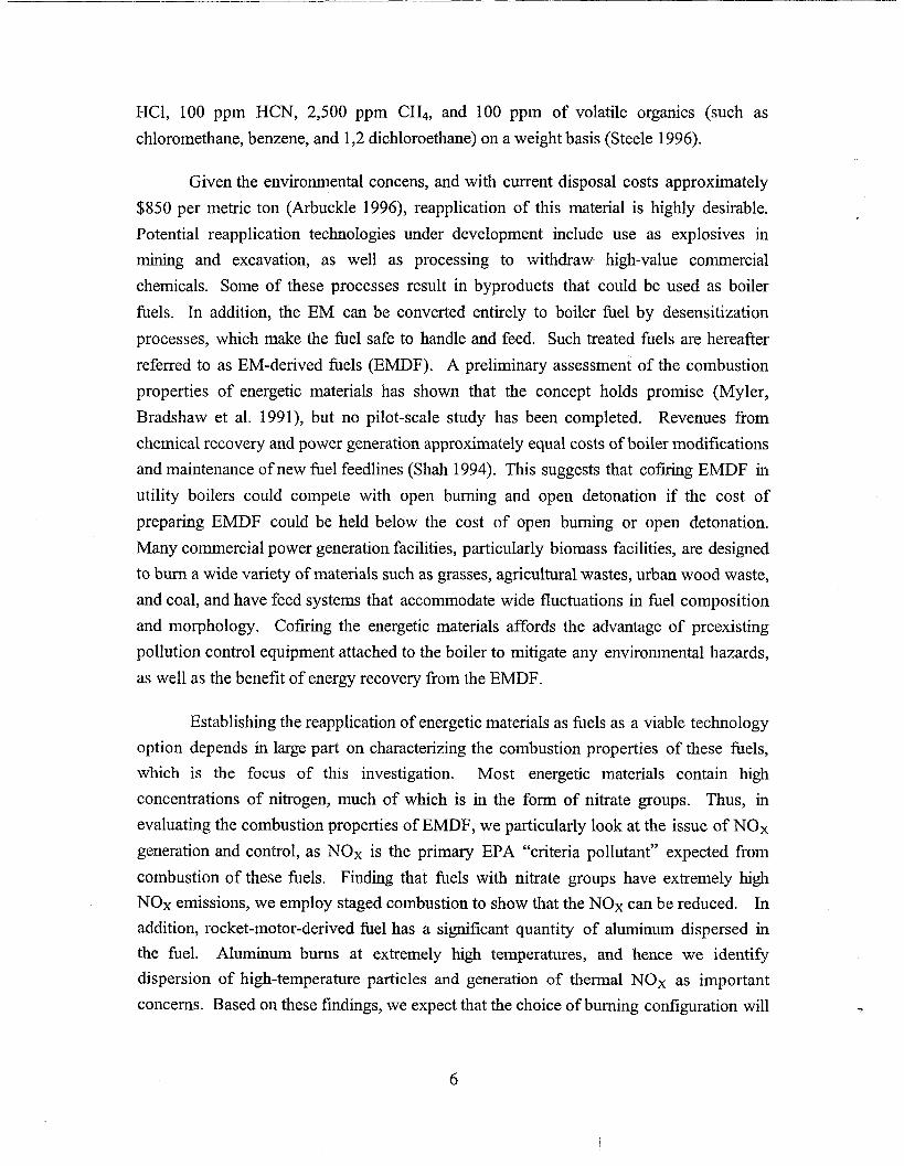
Given the environmental concens, and with current disposal costs approximately
$850 per metric ton (&buckle 1996), reapplication of this material is highly desirable.
Potential reapplication technologies under development include use as explosives in
mining and excavation, as well as processing to withdraw high-value commercial
chemicals. Some of these processes result in byproducts that could be used as boiler
fuels. In addition, the EM can be converted entirely to boiler fuel by desensitization
processes, which make the fuel safe to handle and feed. Such treated fuels are hereafter
referred to as EM-derived fiels (EMDF). A preliminary assessment of the combustion
properties of energetic materials has shown that the concept holds promise (Myler,
Bradshaw et al. 1991), but no pilot-scale study has been completed. Revenues from
chemical recovery and power generation approximately equal costs of boiler modifications
and maintenance of new fuel feedlines (Shah 1994). This suggests that cofiring EMDF in
utility boilers could compete with open burning and open detonation if the cost of
preparing EMDF could be held below the cost of open burning or open detonation.
Many commercial power generation facilities, particularly biomass facilities, are designed
to burn a wide variety of materials such as grasses, agricukural wastes, urban wood waste,
and coal, and have feed systems that accommodate wide fluctuations in fiel composition
and morphology. Coftig the energetic materials affords the advantage of preexisting
pollution control equipment attached to the boiler to mitigate any environmental hazards,
as well as the benefit of energy recove~ from the EMDF.
Establishing the reapplication of energetic materials as fiels as a viable technology
option depends in large part on characterizing the combustion properties of these fiels,
which is the focus of this investigation. Most energetic materials contain high
concentrations of nitrogen, much of which is in the form of nitrate groups. Thus, in
evaluating the combustion properties of EMDF, we particularly look at the issue of NOX
generation and control, as NOX is the primary EPA “criteria pollutant” expected from
combustion of these fuels. Finding that fiels with nitrate groups have extremely high
NOX emissions, we employ staged combustion to show that the NOX can be reduced. In
addition, rocket-motor-derived fiel has a significant quantity of aluminum dispersed in
the fuel. Aluminum burns at extremely high temperatures, and hence we identi~
dispersion of high-temperature particles and generation of thermal NOX as important
concerns. Based on these findings, we expect that the choice of burning configuration will
6

be the most important technical question for combustion of aluminum-containing EMDF
in boilers. Finally, we also address fuel handling techniques throughout the paper..
FUELS
We investigated four different types of EMDF, as shown in Table 1. Readers
familiar with energetic materials will recognize the transportation hazard class rating,
which is a very common means of identifying EM,
Table 1: Energetic Materials Derived Fuels (EMDF) examined in this study.
?
.
EMDF Form Composition Unique Hazard
Feature Class
Double-base Liquid 30’% water, 64% O-NOz bonded 1“1
nitroglycerirdnitrocellulose kerosene, 5’XO to aliphatic
energetic materials, carbon
1‘%0 surfactant
Trinitrotoluene (TNT) Liquid 9570 toluene, 5’XO NOZ bonded to 1.1
TNT aromatic carbon
Nitroguanidine Liquid 95% fiel oil #2, 54% nitrogen 1.1
5’%o nitroguanidine by mass, 3 C-N
bonds,l N-NOz
bond.
Rocket motor propellant Solid Mostly Trace fuel 1.3
(Thiokol) polybutadiene nitrogen, high
rubber impregnated Al cones.
with aluminum,
small amounts of
ammonium
perchlorate
7

Some potential combustion issues associated with high explosives and double-base
propellants (Class 1.1) can be appreciated by examining their chemical structures,
illustrated in Fig. 1. Nitrogen in typical boiler fuels such as coal is dominated by pyrrolic
and pyridinic nitrogen structures (also illustrated in the figure), where the nitrogen is
bound in a carbon-containing ring (i.e. nitrogen heterocycle). In contrast, the forms of
nitrogen in Class 1.1 materials are predominately either nitrate groups or other forms of
nitrogen which are external to the ring. RDX and HMX are notable exceptions, having
both in-ring nitrogen and nitrate groups, but in each case half of the nitrogen is still in the
form of nitrate groups. Among the EMs illustrated in the figure, the weakest chemical
bond in the structure is between the nitrate groups and the remaining structure. As
material thermally decomposes, nitrate groups are expected to be eliminated first, leading
to locally high N02 concentrations. In subsequent reactions, the remaining nitrate groups
sometimes form N20 or similar compounds, which is also expected to form at least one
NOX compound under combustion conditions. Nitrogen not associated with nitrate
groups is expected to form N20 or follow traditional gas-phase nitrogen chemistry
through HCN (Melius 1988; Behrens Jr. 1990; Melius 1990; Behrens Jr. and Bulusu
1991; Behrens Jr. and Bulusu 1992; Behrens Jr. and Bulusu 1992; Cor and Branch 1995).
N02
TNT
HI
Arnmoniumperchlorate (ionicbond)
HN- C “\ H—{- O-N~NeN02
\ H—c—o— N~H I
HNitroguanidine
NitroglycerinNitrocellulose
Typical formsof Nitrogen
in Coal
No\/pyrrole
pyridine
Figure 1. Chemical structures of many energetic materials found in explosives anddouble-base propellants. Chemical structures for the dominant forms ofnitrogen in coal are illustrated for comparison in the box.
8
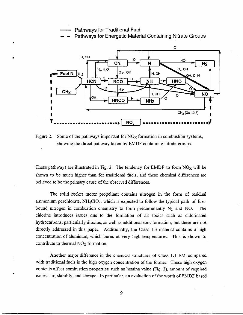
— Pathways for Traditional Fuel-. Pathways for Energetic Material Containing Nitrate Groups
H, OH
g
B
[ CHXa
I
vm==wmmmmmmmmammm ¤ummmm==~@cl
■ mmmmm=mm=mmmm mmmmmmmmmm $
Figure2. Some of thepathways impotiant for NOxfomation incombustion systems,
showing the direct pathway taken by EMDF containing nitrate groups.
These pathways are illustrated in Fig. 2. The tendency for EMDF to form NOX will be
shown to be much higher than for traditional fiels, and these chemical differences are
believed to be the primary cause of the observed differences.
The solid rocket motor propellant contains nitrogen in the form of residual
ammonium perchlorate, NHqCIOd, which is expected to follow the typical path of fiel-
bound nitrogen in combustion chemistry to form predominantly Nz and NO. The
chlorine introduces issues due to the formation of air toxics such as chlorinated
hydrocarbons, particularly dioxins, as well as additional soot formation, but these are not
directly addressed in this paper. Additionally, the Class 1.3 material contains a high
concentration of aluminum, which bums at very high temperatures. This is shown to
contribute to thermal NOX formation.
Another major difference in the chemical structures of Class 1.1 EM compared
with traditional fiels is the high oxygen concentration of the former. These high oxygen
contents affect combustion properties such as heating value (Fig. 3), amount of required
excess air, stability, and storage. In particular, an evaluation of the worth of EMDF based
9
I

on a comparison of standard heating values with typical fiels such as coal can be
misleading. Standardized heating value analyses are based on energy content of the filly
oxidized material per unit mass of fiel. In the case of EM, most of the oxidizer is
contained in the sample. This means that the standard heating value for EM appears to
be much lower than that for other fuels, even though the flame temperature, which largely
determines the thermodynamic efficiency of an idealized power generation cycle, is often
comparable or higher for EMDF.
4.5
4.0
3.5
3.0
2.5
2.0
1.5
1.0
0.5
0.0
I
H HHV/HHVcoal —
H EC/EC coal
Figure 3. Heating values of traditional fiels compared with energetic materials.
Normalization of the energy content of fiels by the mass of the combustion
products provides a more insightfid comparison in terms of flame temperatures and other
properties that determine usefulness of a fuel in heat engines. Assuming air is used as the
oxidizer, values of energy content divided by mass of products for oil and coal are
approximately 3.0 and 2.8 MJ/kg, respectively, whereas TNT and RDX are
approximately 3.6 and 4.6 MJ/kg, respectively. A comparison of both the traditional
10

heating value andthe energy content (heating value based on total mass of product) is
presentedinFig. 3forselected fuels. The left bar ofeachset shows the standard higherF
heating value (HHV)foreachfbel normalizedto the HHVofcoal, while the right bar
shows theenergy content (EC) of the fuels, normalized by the EC of coal. As shown in*
the figure, theamount ofenergy released to the product gasis comparable or higher for
EMthanfor traditional fiels. It follows that EMDFs exhibit flame temperatures that are
as high or higher than those for traditional fhels. In practice, EM used as boiler fuels are
blended with other components to produce more stable materials, and this mixture would
be blended with other fiels to comprise roughly 10% of a fiel stream; hence the impact of
these fiels would be a relatively small, but beneficial effect on ideal boiler performance.
COMBUSTION FACILITIES
The experiments were conducted in the Multifuel Combustor (MFC), illustrated in Fig. 4.
The MFC is a small pilot-scale (=340 kW, depending on fuel type) facility that simulates
the local environment to which independently injected solid, liquid, or gaseous fuels are
exposed as they pass through an entrained-flow combustion system. Fuel is inserted
through any of a series of ports along the 4.25-meter length of the combustor, allowing
variation of residence time from a few milliseconds to 4-5 seconds. Atop the silicon
carbide-lined combustion section is a natural-gas-fired burner, that can be used to control
the gas temperature and composition into which fiels are injected; alternately, fhels can
be injected directly into the combustor airflow with the burner off, where they may form
a self-supporting flame. The combustor wall temperature in each of the modular sections
is independently controllable up to 1400 “C in sustained tests. Gas and wall
temperatures are measured using type K and R thermocouples, respectively.
Combustion products are extracted from the combustor in a heated line to prevent water
condensation, filtered in a heated filter, and measured using analyzers manufactured by
Horiba Instruments, including NDIR NOX, CO and COZ analyzers and a paramagnetic 02
analyzer.
Unless otherwise specified, data reported here were obtained by firing the fiel in the top
section of the MFC and sampling combustion products from the top of the 7* section,
establishing a 3.7 meter reaction section. Given the 15 cm diameter of the reactor, the
9.44 liter/see total airflow, and the wall temperature of 900 “C used in most of these tests,
the residence time in the reactor was roughly 2.7 seconds. Each of the liquid EMDF were
11

burned with a reference case of the solvent fuel without the energetic material. The NOX
control strategy of staged combustion was accomplished by injecting a second air stream
into the top of the 4* section, dividing the reactor into an upper fiel-rich section and a
lower fhel-lean section. Liquid fiel feeding was accomplished using
displacement cylinder feeder, except in the case of nitroguanidine combustion.
NaturalGas/ I i
“r’’amekwkGasBurnerCoal Injection
Lance-Flow Straightener
Coal/AirFlame Laden Stream
Heated/GasFiOW
InsulatedModules
E
‘-+:X+——I—I I ‘ -
a positive-
InsulatingY “--”””
‘ ~ Refrsc!oryLining
I,:&]layers
bH....:??”
J,. . . .
. . -
,.:.:.,.:,.
,.;fir:.:Pcsv .,.
LaserBeam ~‘}
Test sectionfj:t;,j.“:.::/.,.’...t~.
to Exhaust
Figure 4. Schematic diagram of Sandia’s Multi-fuel Combustor.
This fiel mixture was difilcult to fire, as it would separate within about a minute after
mixing. We constructed a pressurized tank with an integral stirring mechanism, which we
mounted very close to the point of injection. This eliminated the separation problem, but
points to the fuel-handling difficulties that may be encountered with some EMDF.
Liquid fuel was sprayed into the combustor with an “atomizing air” flow of roughly 2
liter/see, downstream of the main “combustion air” flow. The ratio of combustion air to
atomizing air determines the shape and mixing parameters of the cone of liquid fiel. A
ratio that is too high or too low can result in poor mixing of the fluid streams and unstable
12

combustion, especially in the case of low atomizing air flowrates; in our experience a ratio
in the range of 4-6 yields good mixing. The solid rocket fuel was prepared by
cryogenically grinding the fiel and mixing it with utility grind coal (76-200 mesh Black
Thunder), which was chosen as a convenient boiler fuel for which the combustion*
properties are well-known. This was fed using a belt feeder emptying into an eductor,
from which the fuel would be transported using high velocity air.
In addition, a limited number of solid rocket fhel combustion experiments were
conducted on a low-density mat of alumina fibers suspended in a Iaminar flow of
combustion gases in Sandia’s Char Combustion Laboratory (CCL). The captive particle
imaging (CPI) system in the CCL monitors individual particle behavior for particles
greater than 80-pm diameter. Particle temperature is also monitored throughout the
particle combustion history.
RESULTS AND DISCUSSION
NOX formation from combustion of EMDF
Figure 5 presents our measured NOX data for the double-base EMDF under different
operating conditions and as a fi.mction of exit 02 concentration. Data from the EMDF are
compared with data from identically prepared material without EM. The base case
(without EM) indicates less than 20-ppmv NOX under all conditions, in part due to the
large concentration of water in the fiel, which keeps temperatures low. The EMDF,
dissolved in the same concentration of kerosene, HZO, and surfactant, was fired at two
different combustion-air-to-atomizing-air ratios, as indicated, which produces different
spray characteristics. NOX samples were collected after complete combustion and
approximately 1.9-s gas residence time, with a temperature of 800 “C at the collection
point. Data are shown on a 3’%0 oxygen basis. The addition of EMDF results in
approximately a 50 to 100-fold increase in the NOX concentrations, to a maximum of
nearly 2000 ppm. Higher NOX concentrations are found at higher excess 02
concentrations, possibly because lower combustion temperatures result in slower
kinetics, which are less able to drive the NOX concentration toward its equilibrium value
of approximately 100 ppm at 900 ‘C. A minor effect of increasing NOX concentrations
with higher ratios of combustion air to atomizing air may be due to the better-mixed, more
dilute spray (lower ratio) burning more completely.
13

NOX data for 2-4-6 trinitrotoluene (TNT) are shown in Figure 6. The bottom curves
show the NOX measured at various oxygen concentrations for a base case of pure toluene
combustion, while the upper curves show NOX measured for combustion of a mixture of
5% (by weight) TNT dissolved in toluene. Figure 6 indicates that the addition of only a
small amount of TNT to the fuel dramatically increases the NOX emissions, attesting to
the efficient conversion of the nitrate (N02) groups of the TNT to NOX. The NOX
generated while ftig pure toluene forms through a combination of promptl and therrna12
mechanisms, and follows expectations, peaking at a few percent oxygen (Miller and
Bowman 1989). In contrast, the 5%-TNT fhel adds a significant loading of fuel- bound
nitrogen, much of which is converted to nitrogen oxides. This results in both a much
higher NOX yield and also a yield that is much less dependent on oxygen concentration.
Under a range of oxygen conditions, measurements of N02 vs NO indicate that NO
accounts for over 90’XOof total NOX.
Combustion air/atomizing air = 9.2
x xx xx x
x x xx x% xx
Wtwxxx
.$?$$?x~xxx$ x
%
xx Combustion air/atomizing air = 5.3x xx
Base case of
U“’’’’:;””r’
o 2 4 6 8 10 12
Excess Oxygen (percent)
Figure 5. NOX emissions from double-base EMDF as a function of exit Oz
concentration, presence of energetic material, and combustion air-to-atomizingair flow rates.
1So-called “prompt” NO forms at the flame front from the reaction CH+NZ=> HCN + N, followed byseveral possible steps (such as N+02 => NO + O) which can form NO.2Thermal NOX forms from the combination of three reactions: N2 + O => NO + N; N +02=> NO + O;and N + OH => NO + H. The first reaction, breaking the N2 triple bond, has an extremely high activationenergy, and so is favored only at high temperatures, giving this mechanism the name “thermal”.
14

1600
1400
200
0
5% TNT in Toluene NOX
adjusted to3% 02.*
Pure Toluene
- -/
%Pure Toluene NOX fl.
u●.%●
u●
o 2 4 6 8 10 12 14 16 18 20
02 (volume percent) ‘
Figure 6. Measurements of NOX concentrations of pure toluene and 5% (by weight)
TNT in toluene, with a residence time of 3.8 seconds and wall temperatures
held at 900 “C.
To fully understand the NOX generation fi-om EMDF containing nitrate groups, it would
be helpfid to be able to determine the yield of each of the source mechanisms for NOX
formation (i.e. thermal, prompt, and fiel-bound nitrogen). The similarities in the
molecular structure of TNT and toluene allow us to make the simplification that the
addition of TNT to toluene adds fuel-NOx formation from the TNT, while the prompt
and thermal NOX concentrations remain equal to the prompt and fuel NOX formed from
toluene alone. This is equivalent to the approximation that the fuel-nitrogen mechanism
does not interact with the prompt and thermal NOX mechanisms. Ignoring interactions
will somewhat overpredict NOX concentrations, as NOX formation is strongly influenced
by NOX concentrations due to reactions such as NO+NO=>NZ+OZ, but this approach
will give an idea of the order of magnitude of the fuel NOX produced from TNT.
Figure 7 recasts the data of Figure 6 to show the NOX formation due to the fiel-
bound nitrogen for the TNT EMDF. The toluene and 5% TNT in toluene NOX data
corrected to 3°/0 oxygen are shown. The shaded area on the graph, equal to the nitrogen
oxide concentrations produced during pure toluene combustion, roughly represents the .
15

NOX produced by thermal and prompt mechanisms during the combustion of 5’XOTNT in
toluene. The remaining area under the 5% TNT in toluene curve, after subtracting the
shaded area, represents the NOX formed from fiel-bound nitrogen. Comparing this with
the dotted line at the top of the graph, which is the calculated NOX concentration if all of
the nitrogen in the TNT were converted completely to nitrogen oxides, it is apparent that
through the entire range of oxygen concentrations (O-18’?40),at least 50’XOof the fuel
nitrogen is converted directly to NOX. Similar arguments hold for the double-base
propellant shown in Fig. 5. In Fig. 7, the peak in the fbel-nitrogen contribution at
approximately 10O/.02 is explained by the fact that at lower oxygen concentrations there
is more competition for 02, favoring the reduction of some of the nitrogen oxides to N20
or N2. The fall-off of fiel NOX concentrations at oxygen concentrations higher than 10’%0
is due to decreasing flame temperature with increasing 02 concentration, as well as the
possibility that at more dilute fbel concentrations less complete combustion is taking
place, and another breakdown pathway in addition to C-N homolysis is becoming
important.
1600
1400
200
0
NOX Concentration if all Nitrogen in 5% TNT in
Toluene produced NOX(adjusted to 3% 02)
$Smaea aa m==
5% TNT in Toluene NOX
““--., adjusted to 3°7L02
‘“ .%..-“. ,,
%Thermal and . . /
ntribution to 5% ..”%.= *..e Combustion ‘“%..
‘n ..-t”
Pure Toluene ~.NOX adjusted to u
.
o 2 4
Figure 7. NOX concentrations from
6 8 10 12
02 (volume percent)
combustion of pure toluene
14 16 18 20
and 50/. TNT in toluene,
adjusted to 30/. oxygen, showing the contribution of thermal and prompt NOX,
as well as the total potential contribution of fuel nitrogen from the TNT.
16

Direct formation of nitrogen oxides from fiel-bound nitrates contrasts with NOX
formation from most nitrogen-containing fuels. Specifically, NOX formation from mostm
fuels proceeds through a reaction pathway involving HCN and NHX as intermediates,
with overall conversion favoring molecular nitrogen. Both the TNT data and the double-@ base propellant data indicate l%el nitrogen conversion el%ciencies that are high compared
to traditional fiels. The interpretation of these data is that NOX is formed directly during
thermal decomposition of these fiels, without proceeding through HCN or other
intermediates, as illustrated in Fig. 2. This aspect of the combustion behavior of EMDFs
sets them apart from essentially all other nitrogen-containing solid fuels. These results
are consistent with thermal decomposition data on RDX and HMX, two other EM with
bound nitrate groups (Behrens Jr. 1990; Behrens Jr. and Bulusu 1991; Behrens Jr. and
Bulusu 1992; Behrens Jr. and Bulusu 1992). A portion of the resulting NOX likely
firther reacts to form Nz, consistent with established NOX kinetics.
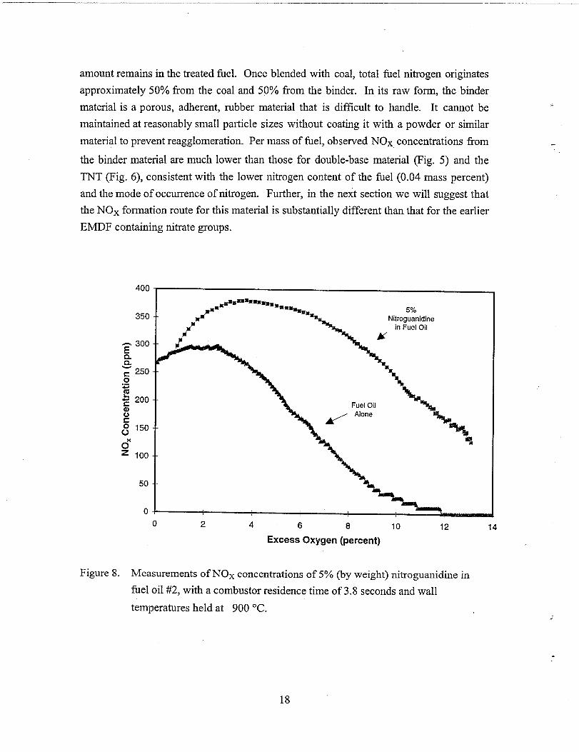
Figure 8 shows NOX data from the combustion of an emulsion of 5% (by weight)
nitroguanidine in fiel oil #2, compared with NOX data from firing the fhel oil alone. When
fired alone, the fiel oil was fired using the positive displacement feeder. Nitroguanidine,
the structure of which is shown in Figure 1, has only a single N02 group, two NH groups,
and an NH2 group, and is thus very different from the previous two fuels. Combustion of
both the double-base propellant (Fig. 5) and the 5% TNT fuel (Fig. 6) shows that the
nitrate groups are readily converted to NOX. However, the direct nitrate conversion to
NOX is somewhat less efficient in the case of nitroguanidine; if only the N02 on the
nitroguanidine molecule were converted to NO, the resulting concentration would be 713
ppm when nitroguanidine is f~ed at 2% excess 02. If all of the fiel nitrogen were
converted into NOX, the resulting concentration would be 2,850 ppm in the product
gases, which is far above both the equilibrium and the measured value. In this case, the
peak measured value of NOX concentration is roughly 380 ppm, which is roughly half of
the nitrate-bound nitrogen, or 13% of the total freed nitrogen. These lower levels of
conversion of nitrogen to NOX suggest that more traditional nitrogen chemistry routes are
dominant for nitroguanidine, consistent with the smaller fraction of fiel-bound nitrogen
present as N02 in this material.
Figure 9 illustrates NOX data for polybutadiene rocket binder material mixed with coal atT
a 65:35 mass ratio. The rocket binder material has no N02 groups; the small amount of
fbel nitrogen present in the fuel is in the form of ammonium perchlorate residual. Thee. intent is to remove all of the NH4C104 during the pretreatment, but inevitably a small
17
amount remains in the treated fuel. Once blended with coal, total fiel nitrogen originates
approximately 50°/0 from the coal and 50°/0 from the binder. In its raw form, the binder
material is a porous, adherent, rubber material that is difficult to handle. It cannot be .
maintained at reasonably small particle sizes without coating it with a powder or similar
material to prevent reagglomeration. Per mass of fuel, observed NOX concentrations from
the binder material are much lower than those for double-base material (l?ig. 5) and the
TNT (Fig. 6), consistent with the lower nitrogen content of the fuel (0.04 mass percent)
and the mode of occurrence of nitrogen. Further, in the next section we will suggest that
the NOX formation route for this material is substantially different than that for the earlier
EMDF containing nitrate groups.
400
350
oxz 100
50
T
I‘Bmm~,=*
=%,u 5%
\
Nitroguanidinein Fuel Oil
K
LFuel Oil
,.- Alone I
o
0 2 4 6 8 10 12 14
Excess Oxygen (percent)
Figure 8. Measurements of NOX concentrations of 5’% (by weight) nitroguanidine in
fiel oil #2, with a combustor residence time of 3.8 seconds and wall
temperatures held at 900 “C.
18

Influence of Aluminum on Combustion Process
R The polybutadiene material is impregnated with flakes of aluminum to increase the
specific impulse of the propellant. Experiments in both the MFC and the CCL indicate
* that aluminum particle temperatures are extremely high during rocket binder combustion.
2000
6z
400
0!o 2 4 6 8 10 12 14 16 18 20
Excess Oxygen (percent)
Figure 9. NOX emissions from the polybutadiene rocket propellant binder material
mixed in a 65:35 mass ratio with coal, as a function of exit 02 concentration
and atomizing air to combustion air flow rates.
In the CPI we have an optical temperature measurement system that is calibrated
up to 1700 ‘C. Single particle combustion experiments were conducted in environments
with oxygen concentrations ranging from 10/002 to 20°/0 02. Under all conditions, the
,particle temperature exceeded the upper limit of our diagnostic. During 12% 02*. experiments in”the CPI, the particles melted through the alumina mat used to hold them.
The A1203 melting point is approximately 2000 ‘C, depending on crystalline structure.
s At 6% 02, the temperature was again higher than 1700 “C, but the particles did not melt
19

through the mat. Coating of particles with coal seemed to reduce their temperatures, but
never below 1700 ‘C. Observations at the remaining oxygen concentrations were made in
the MFC and particle temperatures were very high judging from particle emission, but
particles were not stationary during individual shutter cycles so no reliable temperature
measure could be made.
These high temperatures are believed to induce significant NOX formation through
the thermal formation mechanism. Experimental evidence of this is found by blending
varying ratios of coal and EMDF and analyzing the trend in the NOX data, shown in
Figure
0“z
10.
1400
1200
1000
800
600
400
200
0
❑
70%Coal / 30%rocket binder
A 10U% Coal /O% rocket binder
Figure 10. 1
1
15 16 17 18 19
Excess Oxygen (percent)
Measured NOX concentrations with changes in coal content for a blend of
?olybutadiene rocket binder-derived EMDF and coal.
Coal, which in this case contains about 0.75% fuel nitrogen, is the dominant fhel nitrogen-
containing portion of the blend. The only fuel nitrogen in the EMDF is in trace amounts
associated with residual ammonium perchlorate. If fuel nitrogen is the primary source of
NOX, increases in coal content should increase NOX. The observed trend is the opposite
(Fig. 8), supporting the supposition that the dominant formation mechanism for NO,
20
+

during combustion of rocket motor binder is thermal. These data were obtained at high
oxygen concentrations (low particle loadings) to mimimize complications of changing*
flame structure with changes in blend ratio. At these high oxygen concentrations, there is
no well-define flame front or f~eball, and hence combustionh
individual particles. NOX is believed to form primarily due to
surrounding the aluminum-containing particles.
occurs mainly around
the high temperatures
Our results also indicated that molten aluminum particles exist in flows well afler
1.5 s of residence time. This sustained presence of molten material presents some
deposition threat to a boiler system. In addition, the large amount of inorganic material in
the fiel (the binder is 60% aluminum by weight) could overwhelm particulate cleanup
systems if a high percentage of this EMDF were fired in a boiler. Model predictions of
metal-containing energetic material cofiring conclude that the behavior of ash is the
limiting factor in the amount of energetic material that can be blended with coal for the
particular system considered (Li, Sheldon et al. 1995). The potential for particle
deposition and damage to grates or other equipment from aluminum are concerns in the
reapplication of energetic materials as fiels, but this issue can be managed by blending the
aluminum-containing EMDF with other fiels and by judiciously choosing the boiler
design and operating conditions with which to treat the material. Carefid management of
the fiel on a grate or in a kiln or combustion in suspension, as in an entrained-flow
system, should prevent damage to systems at commercial scale.
NOX Control Strategies
Due to the high levels of NOX generated by EMDF combustion, it is crucial to
demonstrate that commonly used NOX control measures such as staged combustion,
reburning, selective non-catalytic reduction (SNCR) and selective catalytic reduction
(SCR) will be able to adequately reduce the NOX concentrations. This requires that the
nitrogen from the fuel be converted to the gas-phase relatively early in the combustion
process, as each of these methods rely on controlling the gas-phase chemistry to reduce
the NOX formation (as in the case of staged combustion), to convert NOX already formed
to N2 (as in SNCR and SCR), or both (as in reburying). We have chosen to demonstrate
NOX control using staged combustion, the simplest method of the four. Staged
combustion works by burning the fuel in two distinct stages. The first stage is burned
fhel-rich; the lack of excess oxygen in this stage promotes the fhel-bound nitrogen to form
N2 instead of NO, but also leaves a significant portion of the carbon not fully reacted (i.e.
as CO instead of C02, for example). At the beginning of the second stage, excess air is
21

injected, and the second stage burns fiel-lean. This completes the conversion of carbon to
C02 while keeping the temperatures low, thus not promoting thermal NOX formation. A
question at the outset of this investigation was whether or not the first stage would be
effective in converting the fiel-bound nitrogen to N2, when the nitrogen was present in
the form of nitrates.
To look at the effect of chemistry on NOX concentrations, a series of axial NOX
measurements from ftig toluene and 5°/0 TNT in toluene were taken. As expected for
both fiel mixtures, nitrogen oxide concentrations peak in the high-temperature flame
region and then decrease toward their equilibrium value in the cooled gases downstream.
For all of the TNT runs the NOX concentrations near the flame exceed the range of the
meter (1500 ppm). Figure 11 illustrates axial NOX concentration data from toluene
combustion, which are qualitatively similar to the TNTholuene NOX data, at various
excess oxygen concentrations.
1600
1400
oxz 400
200
Upper limit of NOX. . . . . . . . . . . .. . . . . . . . . . . . . . . . . . . . . .detection = 1500 ppm
. . . . . . . . . . . . . . . . . . . . . . . . . . . . . . . . . . . . . . . . . . . . . . . . . . . . . . . . . . . . . .
/
Detector Saturated
Y5% Excess Oz
12% Excess 02
(on axis)
vo0 2 4 6 8 10 12
Distance Downstream of Injection (ft)
Figure 11. Axial NOX concentration data from toluene combustion at various excess
oxygen concentrations, normalized to 3°/0 excess oxygen.
22
*
We do not expect significant radial gradients in the NOX concentration, despite the fact
that the Reynolds number is fairly low (1 500), as the fuel spray is sufficiently dispersed.
The data for l% and 3’%excess oxygen fall almost exactly on top of each other, while the
data for 12% excess oxygen shows nearly zero measured NOX along the entire length of
the combustor. Under all conditions the nitrogen oxide concentrations decrease
monotonically following the high concentrations in the flame as the gases approach the
wall temperature (900 “C). At higher excess oxygen concentrations less NOX is formed in
the toluene flame, primarily due to lower flame temperatures. However, at the higher
excess oxygen concentrations the NOX removal rate also decreases, as the excess oxygen
lowers the rate of removal reactions such as NO + NO => N2 + 02 by Le Chatelier’s
principle. These measurements show the effect of equivalence ratio on both the NOX
production and the rate of NOX removal, both of which are important for understanding
the staged burning technique. The fact that virtually no NOX is formed at the 12°/0 excess
02 condition shown in Figure 11 shows that the lower temperatures associated with lean
combustion prevent the formation of thermal NOX.
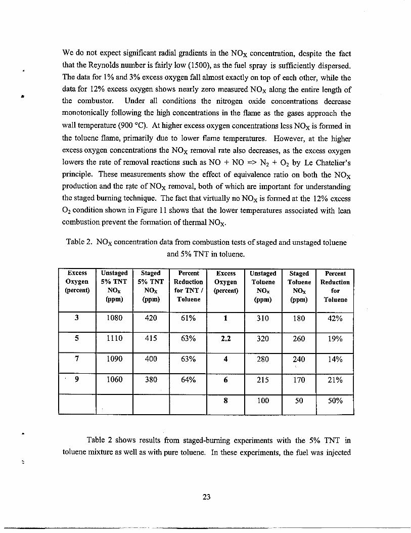
Table 2. NOX concentration data from combustion tests of staged and unstaged toluene
and 5°/0TNT in toluene.
Excess Unstaged Staged Percent Excess Unstaged Staged Percent
Oxygen 5’%0 TNT 5% TNT Reduction Oxygen Toluene Toluene Reduction
(percent) NOX NOX for TNT I (percent) NOX NOX for
(ppm) @pm) Toluene (ppm) (ppm) Toluene
3 1080 420 61’%0 1 310 180 42%
5 1110 415 63% 2.2 320 260 19%
7 1090 400 63% 4 280 240 14%
“9 1060 380 64’XO 6 215 170 2170
8 100 50 5070
Table 2 shows results from staged-burning experiments with the 5% TNT in
toluene mixture as well as with pure toluene. In these experiments, the fbel was injected&
23

at the top of the combustor, air was injected 1.8 meters downstream of the fiel injection
(1.4 seconds residence time), and gas measurements were taken 3.66 meters downstream
of the fuel injection. In all cases, the first stage was run at a constant (fhel-rich)
equivalence ratio of 1.3 and the amount of air injected into the second stage was varied.
The variation of air flowrate to the second stage means that the residence time in the
second stage changes somewhat, but visual observations would suggest that much of the
important chemistry takes place at the beginning of the second stage, in the first 0.5 meter
after secondary air injection, where the fuel burns out. Data corrected to 3°/0 oxygen are
shown for a given excess oxygen concentration at the bottom of the combustor, either
with or without air staging. For both fiels there is a marked decrease in the NOX levels
associated with staged combustion. For the pure toluene mixture the fractional decrease
in NOX concentration is greatest at the highest and lowest excess oxygen concentrations,
in keeping with the fact that most of the NOX is thermally generated; at 8°/0excess oxygen
concentration the staging reduces the NOX by a factor of 2, to a value of 50 ppm. For the
5?40TNT in toluene mixture the effect of staged combustion remained relatively constant
across a range of excess air values, showing in all cases nearly a threefold reduction in NO-
X over the unstaged values. This indication of significant NOX reduction via staging
demonstrates that this and related combustion process techniques will be able to
successfully mitigate the NOX emissions for EMDF, as they do for traditional fuels.
Other Issues
In addition to NOX issues and the behavior of aluminum, the possible formation of
air toxics is an issue for the combustion of energetic material-derived fiels. Air toxics are
conveniently discussed in the categories of inorganic and organic toxics and are delineated
in the 1990 amendment to the Clean Air Act (1989). Inorganic toxics of relevance to
combustion of energetic material derived fuels include beryllium, lead, and trace or
impurity amounts of other toxic inorganic. We have analyzed representative samples of
energetic materials for their total inorganic concentrations using nuetron activation
analysis (NAA). The concentrations are near or below detection limits for all of the
compounds and samples analyzed thus far, none of which include either lead or beryllium
as intentionally added materials. EMDFs containing either lead or beryllium in more than
impurity concentrations (ppm or less) are poor candidates for use as fuels.
Organic air toxics of principal concern include chlorinated aromatic hydrocarbons
in the forms of dioxins, furans, polychlorinated biphenyls
There is a possibility of the formation of these compounds
(PC13S), or their precursors.
when fuels including residual
._.
.
24

chlorine are used, such as binders from ammonium perchlorate-based rocket motors.
Because chlorinated aromatic compounds are rare in the fuel, the formation of theR
compounds, if any, would occur as combustion gases cool in the post-flame environment.
This issue has been addressed for incineration of these materials (Biagioni Jr. 1994), but@
has not been addressed in combustion or power generation systems. In Biagioni’s work,
the total production of firans and dioxins was below regulatory limits. We anticipate
similar results for power generating combustion systems and are continuing work in this
area to validate our conjecture.
CONCLUSIONS
The potential for reapplication of excess energetic materials as boiler fiels has
been economically and experimentally explored. The economics suggest that the cost of
such disposal techniques could be approximately equivalent to the cost of constructing
and operating the facility that removes the material and desensitizes it. Revenues gained
from power generation and chemical recovery are approximately equal to expenses of
boiler modifications and operation and maintenance of new feedlines.
One of the primary combustion issues surrounding EMDF is the formation of
pollutants, especially NOX. In the near-term, the success of EMDF as supplemental
boiler fhels depends in large part on the degree to which proven NOx-control combustion
technologies can be applied to reduce emissions. NOX emissions from combustion of
EMDF containing bound nitrate groups are notably higher than from combustion of
traditional fiels with similar nitrogen contents. The data suggest that thermal
decomposition of the EMDF leads to direct, quantitative formation of NOX from the fhel
nitrogen bound in nitrate groups. We have shown that staged burning effectively reduced
the NOX levels in our pilot-scale system, demonstrating that the NOX formed from
EMDF should be treatable by the same down-stream treatment techniques as are effective
with other fiels. Thus, we expect that were EMDF blended with traditional fhels in a
10% blend, for example, NOX emissions from EMDF would not be prohibitive if staged
combustion or a similar technique such as reburning, SCR, or SCNR were applied.
A second important combustion-related issue for EMDF containing energetic
metals such as aluminum is the extremely high temperatures we found the aluminum-
containing particles to reach in our experiments. Aluminum particles attain temperatures
in excess of 2000 “C, well above the melting point of aluminum, and remain at high
25

temperatures for 1.5 s or more, which is long compared to residence times available in the
furnace sections of most commercial boilers. We found that on a per-mass-of-fiel basis,
NOX emissions from rocket propellant binders containing aluminum are much lower than
for EMDF containing nitrate groups, but still are appreciable. The data suggest much
greater contributions from thermal mechanisms, likely due to these hi@ paficle
temperatures. The potential for particle deposition and damage to grates or other
equipment from aluminum is a concern in the reapplication of energetic materials as fiels,
but we believe that this issue can be managed by blending the EMDF with other fuels and
by judiciously choosing the boiler design and operating conditions with which to treat the
material. Careful management of the fiel on a grate or in a kiln or combustion in
suspension may prevent damage to commercial-scale systems. The ash formed after
complete combustion is benign and should not pose a problem for any combustor except
in quantity.
ACKNOWLEDGMENTS
Funding for this work was provided by Sandia National Laboratories’ Laboratory-
directed Research and the US Governments Strategic Environmental Research and
Development Program (SERDP). Contributions in the form of energetic materials for
testing, desensitization of such materials, and laboratory characterization and
transportation certification were made by Indian Head Naval Surface Warfare Center
(Indian Head), Thiokol Corp., Alliant TechSystems, and Global Environmental Solutions.
The authors gratefully acknowledge Tim Dunn (Indian Head), Louis Kanaras (SERDP and
US Army Environmental Center, Aberdeen Proving Ground), Jim Persoon (Alliant
TechSystems), Kevin Farnsworth (Global Environmental Solutions), and John Slaughter
and Bill Munson (Thiokol Corp.) for their financial support, technical comments, and
cooperation in obtaining energetic materials.
The authors also acknowledge the contributions of many colleagues at Sandia, most
notably Allen Robinson, Joel Lipkin, Jack Swearengen, Donald Hardesty, and Howard
Hirano, in managing this project and critiquing our results,
REFERENCES
(1989). Federal Register: Part III; Air Contaminants.
Arbuckle, J. (1996). Conventional Ammunition Demilitarization Program. 4th
Global Demil Symposium, Sparks, NV.
26

Behrens Jr., R. (1990). “Thermal Decomposition of Energetic Materials:
Temporal Behaviors of the Rates of Formation of the Gaseous Pyrolysis Products from
Condensed-Phase Decomposition of Octahydro-1 ,3,5,7-tetranitro-l 357 -tetrazocine.”3999
Journal of Physical Chemistry 94(17): 6706-6718.
Behrens Jr., R. and S. Bulusu (1991). “Thermal Decomposition of Energetic
Materials: 2, Deuterium Isotope Effects and Isotopic Scrambling in Condensed-Phase
Decomposition of Octahydro- 1,3,5,7-tetranitro-l 357 -tetrazocine.” Journal of Physical999?
Chemistry 95(15): 5838-5845.
Behrens Jr., R. and S. Bulusu (1992). “Thermal Decomposition of Energetic
Materials. 3. Temporal Behaviors of the Rates of Formation of the Gaseous Pyrolysis
Products from Condensed-Phase Decomposition of l,3,5-Trinitrohexahydro-s-triazine.”
Journal of Physical Chemistry 96(22): 8877-8891.
Behrens Jr., R. and S. Bulusu (1992). “Thermal Decomposition of Energetic
Materials. 4. Deuterium Isotope Effects and Isotopic Scrambling (H/D, 13C/1 80,
14N/15N) in Condensed-Phase Decomposition of l,3,5-Trinitrohexahydro-s-triazine.”
Journal of Physical Chemistry 96(22): 8891-8897.
Biagioni Jr., J. R. (1994). “Development of an Environmentally Acceptable
Thermal Treatment Alternative for Energetic Material.” Hazardous Waste and Hazardous
Materials 11(1): 217-226.
Blixrud, C. M. (1996). Demilitarization in the Former Soviet Union. 4th Global
Demil Symposium, Sparks, NV.
Cor, J. J. and M. C. Branch (1995). “Structure and Chemical Kinetics of Flames
Supported by Solid Propellant Combustion.” Journal of Propulsion and Power 11(4):
704-716.
Huizinga, M. (1996). Industry/Government Panel on Conventional Ammunition
Demilitarization. 4th Global Demil Symposium, Sparks, NV.
Li, B. W., M. S. Sheldon, et al. (1995). Feasibility of Cofiring Waste Solid Rocket.Propellants with Coal. Joint Meeting of the American Flame Research Foundation and the
Western States, Central States, and Mexican Sections of the Combustion Institute, San+
Antonio, TX.
27

Melius, C. F. (1988). The Gas-Phase Chemistry of Nitramine Combustion. 25th
JANNAF Combustion Meeting.
Melius, C. F. (1990). Thermochemical Modeling: II Application to Ignition and
Combustion of Energetic Materials. Chemistry and Physics of Energetic Materials. S. N.
Bulusu. Norwell, MA, Kuwer Academic: 51-78.
Miller, J. A. and C. T. Bowman (1989). “Mechanism and Modeling of Nitrogen
Chemistry in Combustion.” Progress in Energy and Combustion Science 15:287-338.
Myler, C. A., W. M. Bradshaw, et al. (1991). “Use of Waste Energetic Materials
as a Fuel Supplement in Utility Boilers.” Journal of Hazardous Materials 26:333-342.
Shah, D. S. (1994). Analysis of Propellants, Explosives, and Pyrotechnics Co-
Combustion in Fossil Fuel and Biomass Boilers as Means of Resource Recovery and
Recycle, White Paper, Sandia National Laboratories.
Sierra (1996). Personal Communications with Sierra Army Depot Staff.
Steele (1996). Solid Rocket Motor Contained Burn Process. 4th Global Demil
Symposium, Sparks, NV.
Wheeler, J. (1996). Opening Remarks. 4th Global Demil Symposium, Sparks, NV.
Wilcox, J. L. (1996). OB/OD Emissions Characterization. 4th Global Demil
Symposium, Sparks, NV.
28

UNLIMITED RELEASEINITIAL DISTRIBUTION
Ms. Alice AtwoodPhysical ScientistEngineering Sciences DivisionResearch DepartmentChina Lake, CA 93555-6001
Dr. Michael BermanAFOSRAFosmcBoiling AFB, DC 20332
Dr. Thomas BoggsNaval Weapons CenterCode 389China Lake, CA 93555
Dr. Surya N. BulusuARDECSMCAR-AEE-WWDover, NJ 07801-5001
Dr. Robert D. ChapmanNaval Air Warfare CenterCode 464220DChina Lake, CA 93555
Dr. Ronald L. DerrNaval Weapons CenterCode 389China Lake, CA 93555
John DowNaval Surface Warfare CenterIndian Head DivisionEnergetic Mat. Res. & Tech. Dpt.Indian Head Division, NSWCIndian Head, MD 20640-5035
Dr. David S. DownsARDECSMCAR-AEE-BDover, NJ 07801-5001
Timothy J. DunnNaval Surface Warfare CenterIndian Head DivisionEnergetic Mat. Res. & Tech. Dpt.Indian Head Division, NSWCIndian Head, MD 20640-5035
Doug ElstrodtNaval Surface Warfare CenterCode 9130Energetic Materials Chemistry DivisionIndian Head, MD 20640-5035
Dr. Robert A. FiferBallistic Research Laborato~SLCBR-IB-IAberdeen Proving Ground, MD 21005-5066
Brad ForthBallistic Research Laborato~SLCBR-IB-IAberdeen Proving Ground, MD 21005-5066
Dr. Arpad A. JuhszBallistic Research LaboratorySLCBR-IB-BAberdeen Proving Ground, MD 21005-5066
Louis KanarasUS Army Env. CenterEnv. Technology DivisionTech. Demon. & Transfer BranchAberdeen Proving Ground, MD 21010-5401
Dr. Solim S. KwakDemil Technology OfficeDefense Ammunition Center & SchoolSIOAC-TDSavanna, IL 61074-6939
Dr. J.A. LannonU.S. ARDECDover, NJ 07801-5001
Dr. Donald LiebenbergU.S. Office of Naval Research800 N. Quincy St.Arlington, VA 22217
Dr. David M. MannU.S. Army Research OfficePO Box 12211Research Triangle Park, NC 27709-2211
29

Walter MarxNaval Surface Warfare CenterIndian Head DivisionEnergetic Mat. Res. & Tech. Dpt.Indian Head Division, NSWCIndian Head, MD 20640-5035
Dr. Ingo W. MayBallistic Research Laborato~SLCBR-113-BAberdeen Proving Ground, MD 21005-5066
Dr. Robert L. McKenney, Jr.Energetic Materials Branch
Englin Air Force Base, FL 32542-5434
Dr. Richard S. MillerOffice of Naval Research800 North Quincy St.Arlington, VA 22217
Dr. Tim ParrNaval Air Warfare CenterCode C02392China Lake, CA 93555-6001
Betsy RiceBallistic Research LaboratorySLCBR-IB-IAberdeen Proving Ground, MD 21005-5066
Dr. Robert W. ShawU.S. Army Research OfficePO BOX 12211Research Triangle Park, NC 27709
Mr. Benjamin StokesTechnical Officer-Propulsion EffectsUSNATO/ISPSC 81 BOX 16APO, AE 09724
Rose Tesce-RodiguezBallistic Research LaboratorySLCBR-IB-IAberdeen Proving Ground, MD 21005-5066
James Q. WheelerDemil Technology OfficeDefense Ammunition Center & SchoolSIOAC-TDSavanna, IL 61074-6939
Merrill Beckstead, ProfessorBrigham Young UniversityChemical Engineering Dpt.350 Clyde BuildingProvo, UT 84602
Professor Melvyn C. BranchUniversity of ColoradoDepartment of Mechanical Eng.Boulder, CO 80309-0427
Professor M. Quinn BrewsterUniversity of IllinoisDept. of Mech. and Indus. Eng.Urbana, IL 60801
Professor Thomas B. BrillUniversity of DelawareDepartment of ChemistryNewark, DE 19711
Professor Thomas LitzingerThe Pennsylvania State UniversityDepartment of Mechanical Eng.University Park, PA 16802
Candace MoreyCornell University125 N. Quarry St. Apt #3Ithaca, NY 14850
Professor Jimmie C. OxleyDepartment of ChemistryNew Mexico Institute of Mining andTechnologySOCOrrO,NM 87801
Jerry ColeEnergy & Environmental Research18 MasonIrvine, CA 92718
Dr. Marc DeFourneauxProject ManagerNIMICInternational StaffNATO-1 110Brussels, Belgium
Kevin FarnsworthGlobal Environmental Solutions, Inc.4100 South 8400 WestAnnex 16
,.
Magna, UT 84044-0098
30

Stan Harding ,Reaction Engineering International “77 West 200 SouthSuite 210Salt Lake City, UT 84101
Leon HydeThiokolPO BOX689MS 130Birgham City, UT 84302-0689
Kathy MiksThiokol CorporationMS 243Brigham City, UT 84302
Bill MunsonThiokol CorporationMS 300Brigham City, UT 84302
John SlaughterThiokol CorporationMS 300Brigham City, UT 84302
Hap StonerTPL, Inc.3768 Hawkins St. NEAlbuquerque, NM 87109
Dr. Larry WaterkmdAcurex Corp.Environmental Systems Division485 Clyde AvePO Box 1044Mountain View, CA 94039
Cesar PrenedaUniversity of CaliforniaLawrence Liverrnore National Laboratories7011 East Ave.Livermore, CA 94550
L-282 R. Atkins
L-282 J. Maienschein
L-282 C.O. Pruneda
MS0828 R.D, Skocypec, 1102
MS 1454 A.M. Renlund, 1514
MS 1452 J. G. Harlan, 1552
MS 1454 L.L. Bonzon, 1554
MS0188 C. Meyers, 4523
MS9001 T.O. Hunter, 8000Attn: 8100 M.E. John
8200 L.A. West8400 R.C. Wayne8800 P.E. Brewer
MS9056
MS9163
MS9052
MS9052
MS9052
MS9052
MS9052
MS9052
MS9052
MS9052
MS9052
MS9052
MS9105
MS0834
MS0834
MS9021
MS9021
MS0899
MS9018
L. Theme, 8120
W. Bauer, 8302
S.W. Allendorf, 8361
R. Behrens, 8361
L.L. Baxter, 8361
S.G. Buckley, 8361
D.R. Hardesty, 8361
M.M. Lunden, 8361
S.F. Rice, 8361
J.R. ROSS, 8361
G.C. Sclippa, 8361
C. Shaddix, 8361
H. Hirano, 8419
K.L. Erickson, 9112
M.L. Hobbs,9112
(5)
(lo)
Technical CommunicationsDepartment, 8535, for OSTI
Technical CommunicationsDepartment, 8535/TechnicalLibrary, MS0899, 13414
Technical Library, 13414 (4)
Central Technical Files, 8523-2