Embed Size (px)
Citation preview


Compiled by
Committee of State Road Authorities
Funded by
South African Roads Board
Published by
The Department of Twnsport P 0 Box 415
ET0 oo@ 1 Republic of South Africa
PRINTED SEPTEMBER 1994

t the rate at which new infor
ion rather than t ner cannot be ex
odd become impractical. Cons r
es each dealing articular subject or relat
CSRA Gu~deiines for the hydraulic des~gn and mamtenance of rwer crossbngs Volume 11, 1994, Committee of State Road Authorhs. South Afr~ca

1.4.1 General
2.33 General
2.4.1 General mntages of continuous decks
2.4.3 Advantages of simply supported decks 2.4.4 Floatation
31 I Introduction 31.2 Responsibility for investigations 3.1.3 Purpose of investigation
CSRU Guideiines for the hydraulic design and maintenance of river crossings Voiurne i l , 1994. Committee of State Road Authorities, South Africa

3.1.4 lnformation required by the designer
(i) General (i i) Spread footings (iii) Piled foundations
(iv) Caisson foundations (v) Approach embankments
33.5 Information required by contractor
(9 Spread footings (ii) Piled and caisson foundations (iii) Approach embankments
33.6 Investigation techniques Remote sensing Geophysical methods Bar-eholes and trialholes (a) Purpose (b) Definitions (c) Choice of equipment (d) Safety of personnel (e) Spacing and depth (f) Records (g) Profile descriptions
Field and laboratory testing
(a) General (b) Shear strength (c) Compressibility tests (d) Heave and collapse mowments (e) Depth of historical scour
(f) Frequency of testing 3.1.7 Foundation investigation reports and contract documents
0 ) Foundation investigation report (ii) Contract documents
3.2.1 General 3.2.2 Design methods 3.2.3 Spread footings
(0 Global behaviour (ii) Selection of pile type
(a) Oscillator piles
jb) Driven tube piles
CSRA Guidelines for the hydraulic design and maintenance of river crossings Volume 11, 1994, Committee of State Road Authorities, South Africa.
(c) Precast concrete piles (d) Underslurry piles (e) Auger piles (f) Forum bored piles
(g) Driven displacement (Franki type) piles
(h) Augercast piles
(i) Caisson piles (or permanently cased bored piles)
(iii) Supervision of installation (iv) Pile capacity design
(a) Ultimate friction design parameters (1) Cohesionless soils (2) Cohesive soils
(b) Ultimate end bearing in soil (1) Cohesionless soils (2) Cohesive soils
(3) Rock end bearing and socket capabilities (v) Pile layout or arrangement (vi) Negative skin friction (vii) Scour and scour depths (viii) Modulus of horizontal subgrade reaction
(a) Cohesive soils (b) Cohesionless soils
(ix) Load and integrity testing of piles (a) Load test (b) Nuclear back-scatter integrity testing
(c) Diamond coring of the shaft and rock (d) Sonic integrity testing
3.2.5 Caissons
0) General (ii) Types of caissons
(a) Pneumatic caissons
(c) Cylinders (d) Open caissons
CSW Guidelines for the hydrau!ic design and maintenance of river crossings
Volume 1 1 , 1924, Committee oi Stale Road Authorit~es, South Africa.

CSRA Gu~clelines for the hydraiii~c design and maintenance oi river crossings
Volume 11, 1994, Commitlee of Siale %ad Authorities, South Aiiica.

OLOG
eneral considerations
Introduction
Lowlevel structure types Foundation parameters
1. I nlroduction
3. ta base for river bridges 4. speclion of river bridges 5. 6. 3. Appendices
CSRA Guidelines tor the hydraulic design and maintenance of river crossings Volume l1 1994 Committee of State Road Authordies South Afrtca

1. l ntroduction 2. Scope 3. Level I risk assessment 4. Level II risk assessment 5. Risk management 6. References 7. Appendices
1. l ntroduction 2. Legislation 3. Legal aspects of designing for a definite flood 4. Court judgements 5. Professional liability
CSHA Guidelines for the hydraulic design and maintenance of river crossings Volume 11, 1994, Committee of State Road Authorities, South Africa.

Symbols not included or varying from those given in this list are of minor importance or are used in s \I?/here they occur, they are adequately explained in the text.
Width of contact (diameter of pile)
Undrained shear strength
ase diameter
Ultimate bond stress between wall of pile and rock
Modulus of horizontal subgrade reaction (cohesioniess soils)
Moduius of horizontal subgrade reaction (cohesive soils)
Standard penetration readings (blows per 300 mm)
Constant of horizontal subgrade reaction
Unconfined compressive strength
Point resistance of Dutch probe
Unconfined compressive strength
Depth below ground
CS!% Guideli~ies for the hydraulic desigri and rnalntenance 01 river crossings
Volume l!. 1994, Cornniittee of State Road Authorities, South Africa.

At times of high flow, several effects come into play and in the event of failure, it is seldom possible to attribute failure to a single cause.
Research done during 1990 on 58 bridge failures in southern Africa since 1902, mainly rail carrying, revealed causes and modes of failure as listed in Sections 1.2 and 1.3 below. Ten failures occurred during 7959, eight occurred during the 1984 Domoina cyclone and five occurred during 1987.
lnadequate bridge openings and inadequate foundations were respeclively the most and second most common direct or contributory causes of failure.
A further common direct cause of failure, noticeably in Natal, m s the location of bridges to take advantage of shallow founding material at the expense of good hydraulic alignment. In such cases flood waters impinged directly on an approach embankment washing it away and in some cases portions of
the bridge as well.
A common contributory cause of failure was debris collection. To a lesser extent contributory causes of
failure were found to be structural design and construction errors.
The most common mode of failure was found to be pier damage or loss (with associated effects on decks), followed by embankment washaways, abutment damage or loss, and displacement of decks.
General
Certain failures could have been averted, had structural shortcomings as listed below been correctly designed and constructed.
B Shallow pile founding due to under-estimation of scour depths and severe limitations in
construction equipment in the earlier years.
W Inadequate bending strength of piles and caissons due to inadequate cognizance taken of scour depth and/or hydrodynamic forces aggravated by debris collection.
a Inadequate restraint and/or lack of air escape vents which resulted in dislodging of decks. (Beam and slab decks particularly prone)
m Inadequate concreting in a caisson due to construction difficulties.
CSRA Guidelines for the hydrauiic design and maintenance of river crossings Volume !l, 1SY4, Committee of State Road Authorities, South Africa.

1-2
P* Inadequate reinforcing steel in a caisson due to a design shortcoming.
M Incorrectly positioned caisson due to obstructions encountered during construction
B inadequate verticai steel in multipie column piers with capping beams which caused bending
failure a4 connections between columns and capping beams and between colurnns and bases.
B Foundations founded on boulders thought eo be bedrock
S Uneven founding of a large caisson which resulted in tilting of the caisson
0986(I).hs CSRA Gu~delines for the hydraulic deslgn and maintenance of rlver crossings
Volume 11, 1994, Comminee of State Road Authorities, South Ahca.

Guidelines on the required hydraulic opening, the location of the bridge, protection works, channel training works, siting relative to embankments, effects of skew, etc. are given in Section 5 Volume I "Hydraulics, Hydrology and Ecologv". This section deals exclusively with components of the bridge.
Pier alignment should correspond as closely as possible with the direction of river flow at the maximum design flow. Supports comprising multiple columns should be used with caution and with the approval of the client as debris collects therein, reducing waterway opening and increasing scour and
hydrodynamic forces. Wall type supports are advocated for this application unless such a configuration adversely affects the flow pattern. If multiple columns are used the minimum clear spacing should be
FIGURE 2.1 : RIVER PIER CONFIGURATIONS
It should be borne in mind thaJ increase in pilecap width will increase scour depth. For this reason the
width selected must be considered together with scour depth to arrive at the most economical solution. (Section 4 of Volume I "Hydraulics, Hydrology and Ecology")
CSRA.Guidel~nes for the hydraulic design and rnmtenance of river crossings
Volume 1 1 , 1994, Con:rniltee of Slate Woad Author~ties, Sou:h Atr!ca

Floatation or buoyancy forces arising from hollow piers must be taken into account when considering overall bridge stability.
The pier ends should be rounded to reduce drag forces and reduce tendency for debris to collect. Drag coefficients for various edge treatments are given in Section 6 of Volume I , "Hydraulics, Hydrology and Ecology".
General
Too many independent and individual requirements influence the selection of abutments to allow meaningful directives to be given. However, some guidelines are given below:
B Spillthrough abutments are undesirable for river structures, unless it can be shown that minimal erosion of the spillthrough material will occur and that the embankment settlements and movements will be within acceptable limits.
S Perched abutments founded in fill should be used only when there is no danger of the
embankment being washed away, i.e., where the flood level is low. This condition may arise when the grade line is dictated by the road geometry. When perched abutments on piles are selected, the system must be stable under flood action, without the surrounding embankment and without live load. The drag-down effect of settling embankments must be taken into account in the design of the raked piles.
a Wingwalls are preferred to return walls unless it can be shown that return walls provide a more economical solution and that the approach embankments will be safe under the action of design flood.
General
Bridge decks commonly used for river bridges fall into two broad categories, namely continuous and simply supported. If adequate support is assured by spread footings on rock or adequate piles socketed into rock, continuous decks are preferred. If there should be doubt about the adequacy of support such as suspect piles, uncertainty about founding stratum, etc. simply supported decks should be considered to facilitate reinstatement in the event of a washaway.
Advantages of continuous decks
The advantages of continuous decks are the following :
M Superior aesthetics.
B Improved rideability.
CSRA Guideiines for the hydraulic design and maintenance of river crossings Volume 11, 1993, Commiitee of State Road Authorities, South Africa.

S Reduced maintenance of joints.
B Reduced risk during construction where construction options such as incremental launching and
balanced cantilever construction methods (which do not require support from the ground or reduce the available hydraulic opening during construction) are used.
R Cost savings in most cases.
2.4.3 Advantages of simply supported decks
The advantages of simply supported decks are the following :
Shorter delays to effect reinstatement if loss of supporl leads to structural failure of the d ~ k during or after construction.
W Decreased risk if decks are supported from ground during construction.
W Convenient configuration for use of precast beams.
2.4.4 Floatation
Decks should be designed to minimise the effects of floatation if liable to be inundated. Beam and slab decks and other deck configurations which will trap air under flood conditions shall be provided with air escape openings (vents) to all compartments. As a general guide the area of the vertical escape openings should be not less than 0,01 O h of the plan area of air trapping compartments. Air escape openings must be placed at high points in compartments to ensure thar all air may escape. Holes need not all be
through the deck as continuity of air escape paths may be attained by providing horizontal openings through webs and/or diaphragms directly below the deck slab. Drainage downspouts located in air tmpping compartments will serve a dual function by allowing air escape as well.
CSFLS Gu.delines for the hydfaulic design and rnalntenance of river crossings \!olurne 11, IS%%, Cornmlt!ee of State Road Authorities, Soulh Africa.

Introduction
Section 3.1 sets out the minimum requirements for foundation investigations for river bridges and is primarily aimed at:
m designers who stipulate the requirements for site investigations,
B geotechnical engineers and engineering geologists who undertake the investigations, and
those responsible for the drawing up of contract documents.
Chapter 3 does not provide details of investigation methods or laboratory tests. However, references are
provided where appropriate.
Responsibility for investigations
Foundation investigations should be carried out by geotechnical engineers (registered professional engineers) or engineering geologists (normally registered natural scientists) who are experienced in the type of work envisaged.
The individual or company appointed to undertake the work should be covered by a Professional Indemnity insurance policy, the value of which should be commensurate with the scope of the work.
conditions.
This document provides guidelines only and does not attempt to prescribe how the investigation should
be undertaken.
Purpose of investigation
Foundation investigations for river bridges have two major purposes:
~ n i The investigations will assist the designer in the selection of foundation types, the preparation of foundation designs and the design of approach fills.
$51 The investigations will provide guidance to the contractor in the pre tion of his tender and for the planning and execution of the work.
The consequences of a poor site investigation are the inappropriate selection of foundation types, inadequate foundation designs, settlement problems and claims arising from unforeseen ground
CSRA Guidel~nes for the hydraulic design and maintenance of river crossings Volume ll, 1984, Committee of Stare Road Aulhorities, South Africa.
3.1.4 Information required by the designer
The foundation investigation report should provide clear guidance for the design en ineer; enabling him to select the most appropriate foundation types for the bridge. The investigation parameters required for the design of the proposed foundations and approach embankments.
The more important requirements are given below:
General
Recommendation as to the appropriate foundation type. Any aspects of the site conditions requiring special design consideration.
Spread footings
Expected depth of founding and nature of founding material. Nature of overburden and stability of foundation excavations. Depth of water table and date measured. Allowable bearing pressures at likely alternative levels. Compressibility of founding material for calculation of foundation settlements. Heaving chamcteristics. Depth of general scour as deduced from material characteristics. Requirements for the inspection and approval of founding material.
Piled foundations
Recommendations as to most appropriate pile type(s). Depth of water table and date measured. Expected pile founding depth, nature of founding material and required confi umtion at pile toe i.e. end bearing, socketed or underreamed. Design parameters for the assessment of pile capacity Consistency/compressibility of material through which the piles are installed for assessment of subgrade reaction. Compressibility of founding stratum for assessment of pile group settlement. Extent of any expansive material and heave forces likely to be exerted on pile shafts. Depth of general scour as deduced from material characteristics. Presence and type of obstructions. Aggressiveness of groundwater. Requirements for the inspection and approval of founding material. Rock classifications in accordance with Table 61 1311 of the CSRA Standad ecifications in order
that quantities may be scheduled accurately and to enable the resident e new to assess the
conditions for payment purposes.
CSRA Guidelines for the hydraulic design and maintenance of river crossings Voiume l!, 1994, Committee of Slate Road Authorities, South Africa.

Caisson foundations
Recommendations as to the most appropriate caisson type(s). Depth of water table and date measured.
Allowable bearing pressure. Requirements for the inspection and approval of founding material. Expected caisson founding depth, nature of founding material and required configuration at the base i.e. end bearing or socketed. Design parameters for the assessment of caisson capacity. Consistency/compressibility of material through which the caissons are installed. Compressibility of founding stratum for assessment of settlement. Extent of any expansive material and heave forces likely to be exerted on caissons. Depth of geneml scour as deduced from material characteristics. Presence and type of obstructions. Rock classifications in accordance with Table 61 1311 of the CSRA Standard Specifications in order
that quantities may be scheduled accurately and to enable the resident engineer to assess the conditions for payment proposes.
Approach embankments
Shear strength of founding soils for assessment of safe side-slopes. Compressibility of founding soils for assessment of settlement embankment and need for pre- loading. Restrictions on mte of construction to allow dissipation of excess pore water pressure. Magnitude of downdrag forces on piles due to settlement of the embankment and founding soils.
3.1.5 Information required by contractor
The foundation investigation report, together with an inspection of the site, should provide the contractor with sufficient information to reasonably anticipate any problems which may occur during the execution of the works in accordance with the specified requirements. This will enable the contractor to submit a realistic price for the execution of the work and to select the most appropriate equipment and construction techniques.
The more important requirements are given below:
(i) Spread footings
B Nature and depth of founding stratum. a Depth of water table, date measured, and expected rate of inflow. S Nature and consistency of material to be excavated. I Opinion should also be expressed on the stability of open excavations and the need for temporary
lateral support.
CSRA Guidelines for the hydraulic design and maintenance of rfver crossings Vol~irne li, 1994, Cornmittet- of State Road Authorities, South Africa.

(ii) Piled and caisson foundations
Nature, depth and hardness of founding stratum. Nature and consistency of the material through which piles or caissons must be installed with
particular reference to boulders or other obstructions. In the case of augured piles, the expected stability of the sidewalls of the auger hole and need For
casing. Depth of water table, date measured and expected rate of water inflow. Special requirements for cleaning of pile holes eg. hand cleaning of bottom of hole or removal of
Nature and hardness of socket material. Trafficability of site and access for piling and caisson installation equipment. Clear description of equipment used for site investigation, drilling rates and diameter of hole.
(iii) Approach embankments
Source and properties of borrow material. B Trafficability of site for construction equipment.
3.1.6 Investigation techniques
The investigation for river bridges normally takes place in a number of phases. These phases include a
desk study and site visit, route/site selection, preliminary field work, detailed investigation and verification of conditions during construction. In certain instances, the process may be iterative prior to final sits
selection and commencement of detailed investigation.
The investigation techniques available fall broadly into four categories, namely remote sensin geophysical methods, direct investigation by means of boreholes/triaiholes and fie1 These techniques are described below.
(i) Remote seming
The most commonly employed form of remote sensing is the study of aerial photographs and photo mosaics. Such photo interpretation normally forms an important part of the route/site selection phas of the investigation.
Aerial photographs, photo mosaics and ortho-photos complement topographical and geological maps of the area and provide planners and designers with an overview of the route or site being investigated Overlapping aerial photographs studied through a stereoscope can provide deraile information with
regard to geological features (faults, dykes, geological boundaries, etc.), soil types and drainage oflecn not apparent even in the field.
This information is valuable not only for site selection but also in the planning of a geotechnical investigation.
CSUA Guidelines for the hydraulic design and maintenance of river crossings Volume It, 1994, Committee of State Road Authorities, South Africa.

Other forms of remote sensing include infrared thermal scanning which can be of assistance in dolomitic areas and satellite imagery.
(ii) Geophysical methods
eophysical methods in common use include seismic, electrical resistivity, electro-magnetic and gravimetric surveys. Of these, the seismic survey is the most common.
Seismic surveys are capable of detecting the location of interfaces at which changes in seismic wave velocity occur and of measuring the seismic wave velocity in the various strata. These surveys provide information on the rockhead topography and an indication of the hatdness and hence excavatability of the rock. Geophones may be placed under water on the river bed permitting the determination of rockhead topography across the river. The results of a seismic sun1ey should be viewed as an indication or approximation of the subterranean topography and must always be confirmed by direct investigation.
lectromagnetic and electrical resistivity surveys are generally used to detect dykes or boundaries between materials with different electric/magnetic properties. Gravimetric surveys are generally used only in dolomitic areas.
(iii) Boreholes and trialholes
(a) Purpose
The purpose of boreholes and trialholes is to permit visual examination and testing of the in situ material or of samples recovered from such holes.
(b) Definitions
The term borehole commonly refers to small diameter holes drilled using rotary core drilling or percussion drilling techniques from which cores or chip samples are recovered. Trial holes generally include shallow backactor test pits or la e diameter auger holes, both of which may be profiled in situ.
(c) Choice of equipment
In most instances, there are definite ad ntages to be gained from usin of type and capacity, for the investigation as will be used for the construction of th
example, where au red piles are to be installed, it is preferable to include the use auger rig similar to t which will be used for the installation of piles, in the site inves where circumstances permit. This will provide a direct indication of the problems likel during construction. Conversely, the use of a bachcror for the excavation of te advantages on a site where shallow spread footings are envisaged. Rotary core rilling is often the most suitable method of investigation below water level.
C S M Guidelines for the hydraulic design and maintenance of river crossings \/olun,e 11, 1894. Gomminee of mate Road Authorities, South Africa.
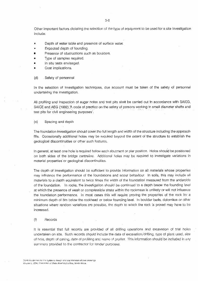
Other important factors dictating the selection of the type of equipment to be used for a site investigation include:
I Depth of water table and presence of surface water. m Expected depth of founding.
Presence of obstructions such as boulders. Type of samples required.
R In situ tests envisaged. H Cost implications.
(d) Safety of personnel
In the selection of investigation techniques, due account must be taken of the safety of personnel undertaking the investigation.
All profiling and inspection of auger holes and test pits shall be carried out in accordance with SAIEG, SAlCE and AEG (1992) 'R code of practice on the safety of p small diameter shafts and
test pits for civil engineering purposes".
(e) Spacing and depth
The foundation investigation should cover the full length and width of the structure including the approach fills. Occasionally additional holes may be required beyond the extent of the structure to establish the geological discontinuities or other such features.
In general, at least one hole is required below each abutment or pier position. Holes should be positioned on both sides of the bridge centreline. Additional holes may be required to investigate variations in material properties or geological discontinuities.
The depth of investigation should be sufficient to provide information on all materials whose properties may influence the performance of the foundations and scour behaviour. In soils, this may include ali materials to a depth equivalent to twice times the width of the foundation measured from the underside of the foundation. In rocks, the investigation should be continued to a depth below the founding level at which the presence of weak or compressible strata within the rockmass is unlikely or will not influence the foundation performance. In most cases this will require proving the properties of the rock for a minimum depth of 3m below the rockhead or below founding level. In boulder beds, dolomites or other situations where random variations are possible, the depth to which the rock is proved may have to be increased.
(f) Records
It is essential that full records are provided of all drilling operations and excavation of trial holes undertaken on site. Such records should include the date of excavation/drilling, type of plant used, size of hole, depth of casing, date of profiling and name of profiler. This information should be included in any summary provided to the contractor for tender purposes.
CSRA Guidelines for the hydmuiic design and maintenance of river crossings Voiume !l, 1994, Committee of State Road Authorities, South Africa.

(g) Profile descriptions
Soil and rock profiles must be described in accordance with guides compiled by SAIEG, SAlCE and AEG (1 992). The use of non-standard terminology can be misleading and give rise to misunderstandings and claims.
Specifications regarding core drilling, percussion drilling, test pitting and augering are published in CSRA (1 992) Standard Specifications for Drilling Investigations.
Wherever possible, the origin of the material should be clearly indicated. In particular, a clear distinction should be made between transported and residual soils. The pebble marker at the base of the transported profile should be identified where present. As an initial assessment it may be assumed that general scour is unlikely to occur in the residual material below the pebble marker unless the flow of the river is significantly altered by the construction of the bridge (Section 4 of Volume I "Hydraulics, Hydrology and Ecology"). Any evidence of recent erosion and deposition of material should also be noted to assist in the assessment of the likely depth of scour.
Where auger holes are drilled to provide information likely to be used for an augured pile contract, the geotechnical engineer or engineering geologist can, with minimal additional effort, provide much information which will be of value to the piling contractor in the preparation of his tender. This information includes an accurate description of the type of auger rig used, the type of teeth fitted to the flight, the rate of drilling particularly near the bottom of the hole, the total drilling time, reasons for stopping the hole (water inflow, refusal, etc.) and the nature of refusal encountered (whether abrupt or gradual). Additional observations to be made during profiling include collapse of s idml ls, depth over which occurs, thickness of sidewall smear and sidewall roughness.
An accurate description of the soil profile using standard terminology is often the most valuable part of a site investigation report.
(iv) Field and laboratory testin
(a) General
The most important design parameters are the shear strength and compressibility of the founding material. These two parameters facilitate the computation of bearing capacity and settlement respectively, The properties of the material above founding level are also important in so far as they affect the shaft friction of piled foundations and the stability of excavations during construction. In certain instances, the corrosivity of the ground and ground water may also be okimportance.
Refer to Tables 6.1 S and 6.1.2 in Appendix 6.1 which provide details of laboratory tests on soils and rocks methods. References are provided in Tables 6.1 .l and 63.2 for fu&her information.
CSfiA Guideiines for the hydraulic design and mainlenance of river crossings Voiume il. 1994, Committee of State Road Authorities, South Africa.

(b) Shear strength
Wirh faz/ exceptions, the direct determination of shear strength tests are carried out in the laboratory,
Where the material being tested is rock, such tests include unconfined compressive strength or point load tests conducted on intact specimens of rock core. However, it must be remembered that the weaker (and hence more critical) layers in the material may not be recovered intact, giving rise to non-representative sampling in which only the stronger portions of the material are tested.
In the case of soils, shear box and triaxial tests are the most common methods of shear strength determination. For the determination of bearing capacity or the long term stability of approach fills, effective (drained) strength parameters are required. In the case of soft clays, the undrained unconsolidated shear strength will govern the stability of fills and excavations during construction.
The most common field test used for the direct determination of shear strength of mainly soft cohesive soils is the shear vane. Such tests may be carried out from the surface using a tripod mounted vane and torque head or in a trial hole using a hand-held shear vane.
In situ tests also provide an indirect measure of the shear strength or bearing capacity of the material, usually based on empirical correlations. Such tests include standard penetration tests (SPT's), dynamic or static cone penetration tests (CPT's) and pressure meter tests.
(c) Compressibility tests
Compressibility of the founding soils may be determined either in situ or in the laboratory.
In the case of rocks, field tests include Goodman jack or pressuremeter tests in NX size rotary core boreholes or plate load tests in auger holes or test pits. Laboratory tests on rocks normally comprise unconfined compressive strength tests in which the vertical and horizontal strain of the specimen is measured by means of strain gauges.
Soil cornpressibility may be determined in the field by means of horizontal plate load tests in auger holes or pressuremeter testing in rotary core boreholes. Laboratory tests include one dimensional consolidation testing in an oedometer or a triaxial consolidation. In both these tests, the rate of consolidation can also be determined. Larger test specimens can be accommodated in the Rowe cell.
As with the determination of shear strength, in situ tests can provide an indirect measurement of compressibility based mainly on empirical correlations. Such tests include SPT's and CPT's.
(d) Heave and collapse movements
Where expansive soils are encountered, heave of the overburden can exert significant uplift forces on pile shafts. Grading and indicator tests or double oedometer tests are frequently used to identify expansive materials and to quantify the amount of heave expected. The magnitude of the uplift forces will depend on the shear strength of the material at natural moisture content rather than in a saturated condition. Such shear strength determination may be carried out either in the triaxial or shear box test.
CSRA Guidelines for the hydraulic des~gn and maintenance of river crossings Volume il, 1994, Committee of Sale Road Authorities, South Africa.

Where expansive soils are investigated, the minimum information to be provided should include grading and indicator test results, in situ density and rncisture content. These should be supplemented with oedometer test results and shear strength test results as necessary.
In some instances, the soils above the water table may exhibit a marked change in stiffness as the moisture content increases. A typical example is soils with a collapsible grain structure which will settle significantly on saturation. In such cases, the results of in situ tests at natural moisture content may produce misleading results. Oedometer tests are normally used in the identification of collapsible soils. In situ densities and moisture contents may also be of assistance but are not reliable indicators.
(e) Depth of historical scour
Apart from the identification of the origin of soils as discussed in Section 3.1.6 (iii)(g), there are f indicators of the likely depth to which general scour had occurred. Nevertheless, careful logging of soil profiles and certain field tests such as cone penetration tests may assist in identifying features which indicate the base of depositional episodes in the transported soil profile. These features include layers of gravel or coarse sand often accompanied by abrupt changes in permeability. Such coarse layers can often be detected by penetrometer refusal on gravel or from samples retrieved from standad penetration tests. Changes in permeability can be detected by piezo-cone penetration tests in which the pore water pressure generated by advancing the cone into the soil is measured.
(f) Frequency of testing
The frequency of testing is left to the discretion of the geotechnical engineer or the engineering geologist.
It is recommended that sufficient tests be undertaken to confirm the relevant properties of each soil horizon which could have a material effect on the performance of the foundations except where the properties can be ascertained by visual observation or experienced judgement. Nevertheless, where a particular property of the material (such as shear strength or compressibility) is critical to the performance of the foundations, it is recommended that at least three tests to determine this property be undertaken on each material type concerned in order to ensure that a representative result is obtained.
3.1.7 Foundation investigation reports and contract documents
(i) Foundation investigation report
The foundation investigation report should accurately reflect the conditions on the site taking due account
of the information required by both the designer and the contractor given in Sections 3.1.4 and 3.1.5. In certain instances, two separate reports may be issued for the designer and contractor.
The foundation investigation report must include the following essential information:
The terms or reference and purpose for which the investigation was conducted (eg whether for planning purposes, foundation design, etc.)
I The precise location of the site.
CSRA Guidelines for the hydrauiic design and maintenance of rlver ciosslngs
Volume il, 1994, Committee of State Road Authorities, South Africa.

A description of the site including regional geology, vegetation, topography and other general features.
A description of the field work giving details of the type of equipment used, problems experience and any other information which may be relevant.
A description of the typical soil/rock profile in each soil/rock zone identifying potential problems which may arise from this profile.
Concise recommendations for the design and construction of foundations and approach fills in particular with regard to scour.
Detailed profile record sheets and the full results from any laboratory and field tests.
Scale drawings showing the location of all testholes and physical features of the site includin setting out points. Wherever possible, the co-ordinates and collar elevations of all testholes shoul be given.
Reference to the method of classification of materials used.
Where information from the site investigation report is summarised on the drawings, all relevant information should be given, including the date of drilling, type of equipment used and any notes given on the original profile log sheets. Particular care should be taken not to omit information regarding the water table. Even where such a summary is given, the full site investigation report should be made available to the contractor at the time of tender.
(ii) Contract documents
It is recommended that the site investigation report be made an integral part of the contract documents. It is undesirable to limit the validity of the report by means of a disclaimer in the contract docume Such disclaimers negate the very purpose for which the investigation was conducted, namely to provld reliable information on which the design would be based and the work be priced and executed. it is preferable to provide in the contract documents a means whereby any deviation from the conditions described in the report can be measured and paid for in a fair and equitable manner,
Insistence that each tenderer verify the findings of the investigation during the tender period results in
unnecessary duplication of effort and is often unreasonable and impractical. Where the contractor is
required to take full responsibility for the ground conditions and their effect on the works as may be the case in certain design and construct contracts, an item should be provided in the contract documents for the carrying out of a further site investigation by the contractor after award of the contract. Provision should be made for Full payment of this contingency in the contract documents.
In the case of design and construct contracts or where alternative foundation designs are permined, full details must be given of the design standards to be met, the loads exerted on the foundations, permissible settlements and the like. Failure to provide such information may lead to the receipt of tender designs based on widely varying assumptions severely complicating the task of adjudicating tenders.
CSW Guidelines for the hydraulic design and maintenance of river crossings Volume 11, 1894, Commitlee of State Road Authorities, South Africa

Summary
The purpose of a site investigation is to provide an accurate assessment of the conditions on the site to facilitate the design, pricing and execution of the work. In order to achieve this objective, it is essential that the work is carried out in a competent manner, soil profiles are described using standard terminology, the results are reported in full and the validity of the information is not disclaimed.
General
Foundations for bridges fall in three broad categories viz. spread footings, piles and caissons. Spread
footings are preferred where they are capable of providing adequate support and can be installed more economically than piled foundations or caissons. Caissons were used extensively in the early years of this century but have lost favour as piling methods and equipment have improved. Caissons should
however always be considered as they provide suitable and economical founding solutions under certain circumstances.
An important consideration in designing river bridges is that of scour. There is ample evidence to suggest that certain bridge failures in South Africa were due to deep scour around pier foundations combined with inadequate founding. This occurred on some of the older structures which were founded too shallow due to the inability of the piling equipment or caissons used to penetrate deeper.
It is thus extremely important to determine the likely scour depth around the pier foundations. The
assessment of scour depth is covered in Volume 1 "Hydraulics, Hydrology and Ecology".
It is essential that foundations are located below expected scour depths or on stable rock. Where foundations are located below the scour depth on material other than stable rock, foundation movements must be within limits that can be tolerated by the structure without distress and impairing its functions.
In the rare case of approach embankments not being in any danger from flood action, spread footings
may be placed within the embankment, provided that allowance is made for settle
Design methods
Ultimate limit state methods for design are generally accepted for the design of bridges, excluding the foundations. The most recent codes generally used in South Africa for foun
S 0160 are based on the working load concept.
The Transportation Research Board Publication 343 (1991) incorporates manuals for the design of various foundation types based on limit state methods and serves as a useful introduction to this design.
ed that the working load concept for the design of foundations is used until the and/or South African codes incorporate the limit state methods.
CSRA Guidel~nes fo: the hydraulic design and maintenance of river crossings Volume il, 1994, Cornminee of State Road Authorities, South Africa.

3.2.3 Spread footings
Careful considerations must be given to the nature of the material at the founding level as well as underlying layers. In particular, the following aspects must be borne in mind:
I Erodability of material at founding level and below. m Nature and extent of rock fractures and bedding planes.
Soft layers below proposed founding level. B Possibility that boulders may be mistaken for bedrock. I Dip of inclined or jointed strata toward exposed faces and discontinuities in strata.
It is not possible to give universally applicable allowable bearing pressures due to the vast variation in conditions and circumstances which apply at different sites. Presumed bearing values which may be used for different categories of foundation materials for initially proportioning foundations are given in (1 986) Refer Table 6.2.1. in Appendix 6.2.
Spread footings on rock should preferably render the structure stable without the use of stressed ground anchors or dowels. If stressed ground anchors can not be avoided, they should be designed to permit checking of residual load in the future. Corrosion resistant dowels may be used provided that the necessary anchorage is assured in the bedrock. Abutments and piers anchored into rock are known to have overturned together with the attached rock, the thickness of which was approximately equal to the dowel embedment length.
3.2.4 Pile foundations
(i) Global behaviour
The glcbal behaviour of piled foundations with their environment should be considered before sbafiin detail design and calculations.
An understanding of the precise interaction of a pile foundation and its environment is still rudimentav, and a designer has to rely heavily on his past experience and observation of the satisfactory performance of similar installations. Fortunately, a considerable body of expertise has been built up wer the years in
the practical design of pile foundations. Nonetheless, oc~asions do occur when there is doubt about the probable performance of a pile foundation, in which case alternative assessments and calculations for favourable and unfavourable assumptions such as degrees of fixity, subgrade reaction, inaccuracy of installation and scour depths are catered for.
The whole foundation system should be sketched before the design is commenced. Pile groups are sometimes designed with consideration being given only to the arrangement of the piles at the cap, with lengths selected independently thereof to provide the necessary bearing capacity, What appears a sensible arrangement of piles at the cap can look totally different if the piles are drawn to full length as illustrated in Figure 3.1.
CSRA Guidelines for Ihe hydraulic design and maintenance of river crossings Volume l!, 1994, Comminee of Slate Road Authorities, South Africa.

FIGURE 3.1 : PlLE LAYOUT
The piles can be spaced at the cap and appear likely to distribute the load to the substratum; while in fact they unnecessarily concentrate the loads at depth. Where piles are not socketed in rock a bridge support may be more efficiently supported by a fan arrangement of piles than by a group with all central piles veflical and edge ones raked as illustrated in Figure 3.2.
FIGURE 3.2 : PlLE LAYOUTS
CSRA Guidelines tor the hydraulic deslgn and maintenance of river crossings Volume il, 1994. Committee of State Road Aulhor~t~es, South Africa.

The pattern of group displacement needs to be considered card~liiy, paa-ticuiariy if the group includes piles of different rakes as shown in Figure 3.3. A pile group under a vertical bad rnay cause differential settlement in the substratum and the outer piles wiahh a pile group may bear in gmund lhal seeales Iess than piles beneath the centre and thus be subjected to much greater and bending kmds. f%iItm
of such piles has been known to take place.
FIGURE 3.3 : DIFFERENTIAL SEVLEMENT
Settlement of an embankment behind an abutment with piles raked backwads can subject these piles to severe bending (Figure 3.4). For this reason back raking piles under an e bankmen1 is db3-l
discouraged. The effects of relative seElemenl between ground and ve h 4 piles are likely m severe and more easily predicted.
FIGURE 3.4 : BACK RAKING PILES ON ABUTME
CSRA Guidelines for the hydraulic design and maintenance of river crossings
Volume 11. 1994, Committee of State Road Authorities, South Africa.

The most serious deficiency of many methods of pile group analyses for abutments is that they do not cater for the influence of lateral loading on the piles caused by the embankment behind. It may in certain instances be reasonable to assume that a dense upper stratum could resist horizontal forces on the fronts of piles, but if the upper stratum is soft, then unfavourable active pressures may be applied on the backs of the piles (Figure 3.5). Even when the ground is firm the strain under the embankment in the region of the piles may cause the ground to displace forwards relative to a stiff pile group. It is usually only
possible during design to make qualitative assessments of the limits of ground stiffness for which passive resistance or active loading are relevant from considerations of the global displacements.
FIGURE 3.5 : HORIZONTAL LOADING ON ABUTMENT PILES
It is advisable to study global behaviour when selecting the factors of safety appropriate for pile design. In a large pile group some variation of pile capacity must be expected and a sub-standard pile is unlikely of itself to jeopardise t t s performance of the group. ut if failure of an isolated foundation as shown in Figure 3.6 could lead to progressive failure of the bridge then a higher factor of safety should be adopted.
FIGURE 3.6 : FAILURE F PILES UNDER AN ISOMTED FOUNDATION
CSRA Guidelines for the hydraulic design and maintenance of river crossings Volume 11, 1994, Commitlee of State Road Authorities, South Africa.

If there is an underlying deposit of weak soil such as soft clay, which will not support, with a reasonable margin of safety, the weight of the soil behind a i l without exceeding t formation on which it is placed, a deep-seated or base failure may occur.
the failure arc passes be1 the tips of foundation them ineffective, is shown in Figure 3.7(a). A deep-seated failure, where piles deposit into a firm d te bearing capacity, is illustrated in Figure 3.7(b). I the load due to the aring stresses in the soft deposit which exceeds i strength. It is therefore unstable and failure will occur along an arc through t pile foundation can resist the lateral thrust it receives from the soft deposit, as figure, in addition to the lateral thrust introduced by the retaining wall. This thrust would commonly exceed the flexu er of piles it is feasible to provide.
.7(a) exist, some solution other than nt might provide a solution or the bridge
cation for the abutment. If parallel retaining walls a
comments concerning the founda er case it may be economi
the firm deposit. If this ak soil, will be large.
designed to carry a thrust which piles could not resist.
TIPS OF PILE (b) FLE
CSPA Guidelines for the hydraulic design and maintenance of r b r crossings Volume 11, 1994, Committee of State Road Authorities, South Africa

Piling contractors are the greatest source of experience on the installation of their types of pile and designers should seek their advice early on in the design process. It has to be appreciated that commercial considerations can influence contractor's advice. However, those offering a wide range of pile types may be able to advise without prejudice on the most appropriate solution. It will be
advantageous to have recourse to an independent expert during the tender period, to assist in the selection of alternative pile designs and verification of associated specifications.
(iij Selection of pile type
Selection of a pile type is an aspect of bridge design for which most designers find it necessary to consult a specialist. Extensive experience is necessary to assess the suitability of the various types of pile for installation in different ground conditions. The choice is influenced not only by cost but also by the nature of the soil and groundwater conditions, the type of plant used, the competence of the contractor and access to the site. The installation process can increase the strength of some soils and decrease the strength of others. The selection may even not be straightforward to an expert, if he does not have experience in the use of identical piles under similar conditions, and he may well request a trial installation to confirm his choice.
There are at present eight pile types that are regularly used in South Africa. These are listed hereunder in the order of their general suitability, for bridge foundations. In addition to these eight, the Caisson pile (or permanently cased large diameter bored piles) has been used on a number of river bridges in the past but is not widely used at present because of the high cost of the permanent casing. As it has its uses it has been included for completeness. Particular sub-surface conditions may rule out the suitability of one or more of the pile types. A detailed description of these pile types is given by Braatvedt (1986).
Oscillator Piles Driven Tube Piles Precast Piles Underslurry Piles Auger Piles Forum Bored Piles Driven displacement (Franki type) piles Augercast Piles Caisson pile
ored cast in situ large diameter Driven cast in situ medium diameter Cl iven pre-formed small diameter Bored or augered cast in situ large diameter Augered cast in situ full range Bored cast in situ small diameter Driven cast in situ medium diameter
Augered cast in situ medium diameter Bored cast in situ large diameter.
All of these pile types could theoretically be used for river bridges. However, in practice the subsurface material typically found on river bridge sites will limit the choice considerably. Client bodies furthermore also have their own requirements which limit the choice of pile type. In the following examination of the various systems the ositive and negative features of each system with regard to river bridge foundations are summarised.
(a) Oscillator piles
This is the pile type most often used in South Africa for major river bridges which are prone to scour problems.
CSRA Guidelines for the hydraulic design and maintenance of river crossings Volume 11, 1994, Committee of State Road Authorities, South Africa.

The positive features are:
a The diameters available are in the range 900 to 1500 mm. These sizes can accommodate the
large moments and shear forces.
The syste tion through most sub-strata obstructions such as boulder an layers.
S The system is suitable for the forming of a rock socket for increasin
The installation of these pi1 e accomplished un M be accommodated if required. 0 chieved with the system.
The depth capacity of the system is considerable (piles up to 65 m deep have been installe
ative features are:
The cost of these piles is relatively high.
The system is not suited for foundin in cohesionless soils below the le as the associate installation disturbance of the founding material will result in a rastic reduction in the end bearin component of the pile's capacity.
The pile diameters that are available with the oscillator system are related to the size of t casing. These are 1080, 1200 an 1500 mm outside diameter. As the temporary casi thickness of 50 mm the resulting pile diameter is 100 mm less than the outside diameter. I casing is not used, the pile iameter will be equal to the outsi e diameter of the tempora
The range of permanent casin
S 00 or 950 mm dia for the 10 0 mm temporary casing size. S 1000 or 1050 mm dia for the 1200 mm temporary casing size. M m dia for the 1500 mm temporary casing size.
It shall be noted that casings with iameters smaller than the I r limit will be inade within the temporary casing while casin S with diameters larger than the upper limit wi clearance to the temporary casing.
The oscillator pile is ca le of penetrating all soil types obstructions. Th the harder they are e more difficult and
using explosives.
Penetration into the bedrock depend on the hardness of the rock and the amount of fracturi weathering of the for an unconfined compression stren th (ucs) of less than which is classified as a very soft rock ( 1) or a soft rock (R2) can be socketed into fairly
CSRA Guidelines for the hydraulic design and maintenance of river crossings Volume 11, 1894, CommMee of Sate b a d Authorities, South Africa

irrespective of the amount of fracturing. Socket lengths in these grades of rock of up to 4 to 5 pile diameters can be achieved.
Penetration into medium hard rock (R3) with a ucs of 10 to 25 MPa also presents little difficulty with the more fractured rock being easier to penetrate. Socket lengths should be limited to 1,5 pile diameters or 2 metres whichever is the lesser if the rock is massive, and 2,5 pile diameters or 4 m if the rock is fractured.
When the rock is classified as hard rock (R4) with a ucs of between 25 and 70 MPa, socket penetration will depend to an even greater extent on the fracturing of the rock. Rock types such as sandstone, dolerite, granite and quarlzite are difficult to penetrate if they are in a massive state. In these
circumstances the socket length should be limited to 1,O pile diameters or 1,5 m whichever is the lesser. If the rock is heavily fractured, penetration is achieved much more readily and a longer socket length of say 1,5 to 2,O pile diameters with a maximum of 3 m can be used.
In very hard rock (R5) with a ucs in excess of 70 MPa which has little if any fracturing, penetration will prove very difficult. Socket lengths should not exceed 0,5 pile diameters and the alternative method of using dowels as described hereunder should be considered in these circumstances, However, if the rock is fractured a socket length of 1 ,O piie diameter or 1,5 m, whichever is the lesser, can be achieved without using special techniques.
With the alternative dowel anchoring, the surface of the rock shall be levelled off within the temporary casing area and whereafter the pileshaft shall be constructed with drilling sleeves cast into the concrete for the subsequent drilling of the dowel holes. Once the concrete has hardened the dowel holes shall be drilled into the be rock and the dowel bars grouted into the holes. The dowels shall be designed to resist the applied loads.
Explosives can be used :o facilitate the penetration of a pile socket into vary hard rock. Severe shattering can occur from blasting and therefore the use of explosives should be used with caution.
Normally a self compacting concrete is used and because of the high slump, the m imum 28 day cube strength that can be achieved is limited to 35 MPa. Concrete cover is normally 75 mm.
The reinforcing comprises a cylindrical cage with main bars of 25 or 32 mm diameter. The transverse bars vary between 8 to 12 mm in diameter and are either in the form of conventional circular hoops or spirals. Sufficient circular hoops shall be provided to stiffen the cage to facilitate lifting at one end into the vertical position without permanent distortion of the cage.
(b) riven tube piles
There are a number of major bridges in South Africa that are founded on this piie type which has since the introduction of the oscillator pile, been overlooked. It can provide an excellent foundation for a river bridge and is often less expensive than the oscillator pile.
CSRA Guidelines for the hydraulic design and maintenance of river crossings Volume 11, 1894, Committee of State Roed Authorities, South Africa

The positive features are:
The pile can be installed to considerable depths. Depths in excess of 50 m have been achieved.
The internal bore of the pile can be inspected prior to placing the concrete.
The concrete in the pileshaft can be placed in the dry and thus higher strength concrete ca used. There is generally better control of the concreting with a resulting better quality of pile
The pile is driven to a "set" calculated to provide the required capacity. This avoids the pm the adequacy of the founding conditions as is the case with bore
the pile is a driven displacement type, the shaft friction generated contributes apprecia the pile$ bearing capacity
rovides a good solution where piles are to be founde table. In these conditions bo er from reduced friction a caused by disturbance of the sand.
E Raking piles of up to 1 in 4 can be achieved with the system.
The negative features are:
The ability of the pile to penetrate a particular soil stratum is often difficult to assess at the desi stage and the presence of boulders and cobbles makes the assessment even more difficult. However, experience has sh n that where the matrix between the boul ers and cobbles is not dense the pile will pe etrate such layers. In sandy materials penetration over the upper 15 m c
e diameter of the pile is limited to a maximum of 600 mm.
I the system utilizes a thick ermanent casing the cost per meter ten
The diameter of t ile can vary between 250 and 600 mm. sed on the standard tube sizes available. The mini
h the onus on the contractor to adopt the thickness
The toe end of the tube is closed o ith a steel plate of which the thickness thereof should not b than 4 percent of the piie diamete d the outside diameter thereof should be 20 mm larger than outside diameter of the tube. A rock penetmting point with locating gusset plates can be welded to th
in penetrating boulder and cobble layers. A rock point is essential when foundi
d once the first section has asings can be butt t the use of an outer collar splice is preferable. This collar is we1
CSRA Guidelines for the hydraulic design and maintenance of river crossings Volume 11, 1994, Committee of State Road Authorities, South Africa

the collar, lined up and a fuil penetration fillet weld made between the collar and the casing to ensure continuity of axial and bending strength.
The quality and workmanship in the manufacture of the casing is extremely important and shall be in accordance with a recognised specification. Random ultrasonic and/or X-ray tests shall be carried out
on the welds. Experience has shown that the barrel type tube construction has been more reliable than the spiral welded type. Barrels of up to 9 m in length can be handled by the installation rig thus limiting the number of circumferential welds.
The reinforcing cages are fabricated as for those in oscillator piles. Main bars are typically either 25 mm diameter or 32 mm diameter with the lateral tie being an R 8 spiral with half pile diameter pitch. As the cage is small in diameter, stiffening rings will only be necessary for the heavier cages.
40 MPa concrete can be accomplished in the shafts of these piles. The concrete cover over the reinforcement tie bars varies generally between 50 and 75 mm.
(c) Precast concrete piles
Because of the slenderness of these piles they are normally only suited to river bridges where scour is not likely to be very significant. In such cases the precast pile can provide a very economical foundation solution.
The positive features are:
High rate of production which results in shorter construction times.
High quality pile shaft provided it is not damaged during driving.
ointed rock shoes can key into sloping faces where the rock classification is R2
or softer.
Jointed piles can be installed to considerable dep-h. (Depths of 50 to 60 m have been achieved).
Precast piles have a good penetrating ability provided there are no la e boulders or other large obstructions present. Cobble layers can be penetrated provided the matrix is not dense or cemented.
Loads are resisted by friction and end bearing. Precast piles need not be founded on rock and are often founded in a dense sand layer.
Precast piles can be installed to a rake of up to 1 in 4.
CSRA Guidelines for the hydraulic design and maintenance of riwr crossings Volume 11. 1984, Commlnee of Slate %ad Authorities, South Africa.

3-22
The negative features are:
Non-jointed piles are limited in length to about 15 m.
H The piles are relatively slender with the result that limited shear and moment can be resiste
H There may be concern about corrosion resistance of the pile joints especially if the piles are designed to resist tensile forces.
The pile len e determined prior to installation. Unforeseen changes in the foun levels can result in excessive S or alternatively
C Pileshatts can fracture during drivin
Size and cross-section (square, hexagonal or round) preferences vary be en contractors. The most common available cross sectional areas are 60 000, 90 000 and 120 000 square millimetres with the most common shape being square.
al steel reinforcing in precast piles is normally in excess of 1 percent of the cross-sectional ing and driving purposes. The main bar size is 16, 20 or 25 mm and high tensile steel is iral at 100 to 150 mm centres reducing to 50 mm centres at the section ends is typical.
The shaft stresses in precast piles under working loads, is generally 16,5 Pa when used in buil foundations. For river bridges there are grounds to suggest that this shoul e limited to 12 MPa. The concrete in the piles should have a minimum 28-day cube strength of 50 MPa.
(d) Underslurry piles
This piietype was introduced to South Africa in 1975 and has not been used on ntany brid because of the fact that raking piles cannot be achieved with this system.
hile a detailed description of this system is given in Braatvedl (1986), it is im ortant to note that piles are split into two groups. The Auger underslurry piles which are excavated using conventional a rigs whereas the BarreEe is excavat.4 using a special rab. With the former the pileshatls are ci and the latter rectangular or special shapes comprising rectangular components.
The positive features are:
Vertical pileshafts of lar e cross sectional area can be instailed to consi 42 m.
The cost of supporting the excavation using bentonite slurry is generally much less than that of
The physical dimensions of the arette type of pile are suited to resist large horizontal loads.
CSRA Guidelines for the hydrauiic design and maintenance of river crossings Volume 11, 1994, Committee of State Road Authorities, South Africa.

B! otary rock drilling can be used down a bentonite slurry supported excavation for forming rock
sockets. Considerable depths of penetration into rock can be achieved.
The negative features are:
B Only vertical piles can be installed.
S The system is regarded as having a poor penetration ability without the assistance of drilling equipment. It is thus not suited to sub-strata which have a proliferation of boulders although cobbles in a loose matrix can be penetrated.
B The formation of a rock socket is not achieved easily and is not normally attempted unless the rock is soft enough so that it can e drilled using an auger rig. Harder rocks can be drilled with rotary rock drilling equipment. The formation of rock sockets on Barette type piles is even more difficult and should only be attempted in exceptional circumstances.
ith the auger underslurry pile the sizes are normally those used with conventional auger piles with a minimum size of 900 mm diameter and a maximum of 1500 mm. Larger sizes can be achieved in ideal soil conditions. The depth of these piles is limited to a maximum of 42 m with the equipment presently available in the country.
arette piles are rectangular in shape and can vary in size from 2200 by 600 mm to 2200 by 1200 mm for a single pass of the grab. Longer panels and shaped panels can be constructed in a manner similar to that used in the construction of a diaphragm wall. The depth of Barette piles is not limited as the grab is cable suspended.
einforcing cages for the circular piles are as for the oscillator pile. For Barette piles the cage is rectangular with longit~dinal and distribution steel on both of the longer sides. To stiffen the cage, diagonal bracing bars similar in shape to shear steel are used. These bars should be kept well clear of the centre of the cage so as to allow unrestricted passage for the tremie pi
The concrete used generally attains a-minimum 28-day cube stren Par - --
This is one of the most widely used pile types in South Africa as it provides an economical solution especially in the interior of the country where the soils are gene Ily cohesive and where there is an absence of a water table. The pileshafts are excavated with an auger rig and under the abwementioned circumstances lateral support to the excavation need normally not be prwided. Auger piles are normally not suitable for use in river beds due to the frequent
resence of shallow ter tables and the cohesionless nature of many river substrata. In exceptional eases where the substrata contains some clay and the water table is very deep, auger piles could be considered.
CSAA Guidelines for the hydraulic design and maintenance of river crossings Volume 11. 1994, Committee of State Road Authorities, South Africa.

The positive features are:
A fast and economical piling system.
B The system has a great flexibility in the size of pile which can vary from 150 to 2000 mm in diameteK
m ke of up to l in 4 can be installed.
Auger rigs can penetrate the softer rocks (classification R2 and softer) so good end bearin form of a rock socket can be achieved in most cases.
S eters greater than 750 mm loose material at the toe of the pile can be remove hand in order that the end bearing of the pile is not impaired.
m The concrete can be placed in the dry with the resulting better control of this operation.
The negative features are:
The system is most suit to soil conditions where the pile excavation will not colia Temporary casings can be used where local collapse occurs but this will tend to render the system less economical. It is sometimes difficult to forecast beforehand whether the pile excavations will collapse or not.
Auger rigs cannot drill through the hard boulders larger than about half the pile diameter or wit a least dimension of 300 mm, whichever is the lesser dimension. These have to be rem special techniques which are best executed in the dry. If boulders are present and there is a risk of the hole collapsing, the oscillator pile is preferred.
One of the major advantages of the Auger system is the flexibility with the size of the pile. The dia can range from 150 to 2000 mm. For river bridges, however, the normal sizes are 750, 900, 10 1350 and 1500 mm. Most truck mounted auger rigs can drill to 36 m depth but there are crane auger rigs in the country that can drill up to 42 m deep. Auger piles with a diameter of less than 7 are not recommended for river bridges as they cannot be cleaned out adequately prior to conc
Auger piles can be installed to a maximum rake of one in four, It is advisable, however, to limit the dept of raked auger piles to about 15 it is not possible to prevent the auger tending to dip over the lo lengths and more inclined rakes. g raking auger piles tend to have a egree of curvature in the caused by dipping of the auger.
The installation of temporary casings on a rake is also difficult especially if the ke is more inclined t one in eight. Under conditions of collapsing soils in conjunction with raking piles it is advisa an oscillator type of pile rather than the auger pile.
le of drilling into the softer rocks i.e. cl
end bearing component of the pile capacity at a wor
5 MPa if refusal of a Williams Digger is achieved. Penetmtion into harder rock can b
CSRA Guidelines for the hydraulic design and maintenance of river crossings Volume 11, 1094, Commiliee of State Road Authorities, South Africa.

where the rock has natuml planes of weakness or fractures. Friction on the sides of a socket can greatly increase the pile's bearing capacity. (Section 3.2.4(iii)).
The reinforcing steel cages are made up as for the cages for the oscillator piles. Concrete strengths in excess of 40 MPa at 28 days can be attained if the concrete is placed in the dry.
(fj Forum bored piles
'This is a smaller diameter (410 and 600 mm) bored cast in situ type of pile which can either be socketed into soft rock (R2) or can be founded in soil by forming an enlarged base. The system is suitable for use on smaller river bridges.
The positive features are:
M The equipment is light, so establishment costs are low. It is thus suited to small river bridges in remote areas.
B The small rig can be manoeuvred into difficult access and low headroom situations. The system
has thus been used in the past to underpin existing footings or to extend existing piled foundation on bridge widenings.
S A rock socket or enlarged base can be formed to resist uplift forces.
S As the system makes use of a temporary casing, the presence of a water table is normally not a problem in cohesive materials. However, the presence of clean sand below t
licate the installation as it is difficult to seal the casing against the inflow o sand. The pile can normally e installed successfully pravided that there is a final cohesive layer in which the casing can form a seal.
R The reinforcing cage can be extended into the enlarged base and thus these piles can resist ble tensile forces.
The negative features are:
W The diameter of the pile is limited to 600 mm.
B The system has a depth limitation of about 12 m.
88 For reasons stated above, the system is not suited to substrata comprising clean sand below the irectly overlying hard rock.
B Some authorities are not in favour of the shaft concrete coming into contact with the saturated soil on extraction of the temporary piling tube as is the case with this pile type.
pile sizes available which are 410 and 600 mm diameter but the former is the more common size. The working load for the two sizes is 600 and 1000 kN respectively.
CSRA Guidelines for the hydraulic design and maintenance of river crossings
Volume 11, 1094, Committee ot State Road Authorlt~es. South Africa.

(g) Driven displacement (Franki type) piles
This is one of the most widely used piling systems in the country and there are a number of bri founded on this pile type. Its use on river bridges is not very common for reasons stated below under negative features. The Franki pile system is the most common of this type used in South Africa.
The positive features are:
The pile is formed with an enlarged base. The action of enlarging the base in the ground results in the end bearing capacity being far superior to that of most other pile types not founded on rock. The system is thus ideally suited to shallow founding in softer ground especially sandy material.
The reinforcing cage can be extended into the enlarged base and thus these piles can resist considerable tensile forces.
The piles can be raked at up to 1 in 4.
The negative features are:
E Some authorities are not in favour of the unset shaft concrete coming into contact with the saturated soil on extraction of the temporary piling tube as is the case with this pile type.
The system has a depth limitation of 15 m.
The size range is 41 0,520 and 61 0 mm diameter for working loads of 750,1200 and 1600 k
As this is a driven pile, the substrata must be suited to the driving of piles. In non-collapsing ground conditions the pile can be predrilled to achieve the founding depth and to spee up the installatior~ process. In dense sands water and air jetting can be used to facilitate penetration.
This pile type can also be installed in what is known as the Franki precast composite pile in which a
precast shaft is used in combination with an enlarged base. This technique has been used in cases where the client or engineer is concerned about unset concrete coming into contact with saturated soil in W
there could be ground water movement. These piles perform very well in compression ut the connection between the precast shaft and the enlarged base cannot resist tension.
(h) Augercast piles
This piling system is least suited to river bridge work. The system is very operator- limited control on aspects such as cover to the reinforcement. Decompression of satu soils occurs during the drilling operation which reduces the friction bearing component in these su Where possible these piles should be founded on rock where end bearing capacity is not affecte drilling operation.
nge of pile sizes is 300 to 750 mm with 300, 400, 500, 600, 750 mm being the most common sizes. Depths of u to 20 m can be achieved. The pile rakes should be limited to one in six.
CSRA Guidelines for the hydraulic design and maintenance of river cmssings Voldme 11, 1894, Committee of State Road Authorities, South Africa.

A sandlcement grout is used in the pileshafts for these piles in lieu of concrete. The main reasons for this are that grout can more readily be pumped through the hollow stem auger than concrete and it is easier to place the reinforcing cage into grout than into concrete. The working stress on these pile shafts is normally limited to 6 MPa.
(i) Caisson piles (or permanently cased bored piles)
This name can be confusing but the term is used to refer to large diameter pi!es with a permanent casing. The system and the method of forming these piles is described by
The positive features are:
S Large pile diameters can be achieved.
S In certain substrata such as impermeable clay a seal against water inflow can be formed between the permanent casing and the founding substratum. Such a seal will allow the casing to be de- watered and the socket in the founding substratum to be inspected prior to concreting the shaft.
The permanent steel casing can be utilized to contribute to the overall strength of the pile.
W By using a telescopic casing configuration great pile depths of the order of 80 m can be achieved.
I Bending moment and shear force resistance are higher than those possible with other piles of equimlent size due to the permanent casing and the higher concrete strengths which are attained when casting the concrete in dry conditions.
m The piles can be ked up to 1 in 4.
The negative features are:
h cost of this pile when a thick lled permanent casing is used
The permanent casing can be damaged in the rocess of driving it throug oulders layers and other hard obstructions. If there is a predominance of boulders in the subst then an oscillator type of pile is most likely the better choice.
iie diameters 900, 1000, 1200, 1350 and 1500 mm are the most common. The 28 day concrete cube strength in the pileshafts is normally a 35 MPa or lower but 40 MPa can be aMained if the concrete is placed in the dry.
ided by the cash itudinal reinforcing bars tied together with helical d welded hoops formed from 35 x 6 mm mild steel strips spaced at 2 m centres. rable subsurface conditions from a corrosion and abrasion point of vi he level of oxygen replenishment over zones where the river flow velocity is less
n flood) the outside diameter of the casin
CSRA Guidelines for the hydraulic design and maintenance of rivar crossings Volume 11, 1994, Committee of State Road Authorities, South Africa.

less when calculating the stresses in the pile. An assessment shall be made of the corrosion and a conditions and a suitable sacrificial layer allowed for in the design to account for loss of cross-section.
(iii) Supervision of installation
The importance of vigilant supervision of installation to ensure that the designer's requirements are met
cannot be stressed too strongly.
(iv) Pile capacity design
Most piles used on river bridges are founded on rock and are therefore predominantly end hearin Frictional resistance capacity can however be a substantial component in certain cases and there are no grounds for ignoring it, except in cases of scour. In some cases it may prove economical to found a bridge on friction piles which have little or no end bearing capacity
To enable the designer to make a rough assessment of a pile's bearing capacity, some design pa are given in Tables 3.1, 3.3 and 3.4. These are ultimate friction and end bearing values to which a factor of safety of between 2,5 and 3,O should be applied to arrive at allowable working loads. Braadvedt (1 986) page l48 for a bearing capacity formula.
(a) Ultimate friction design parameters
(1) Cohesionless soils
Design parameters for ultimate skin friction stresses are given in Table 3.1.
Oscillator Piles (uncased) (cased)
Driven Tube Piles Precast Piles Underslurry Piles
Auger Piles Forum Bored Piles Driven Displacement Piles Augercast Piles Caisson Piles
qc/180 or 3 N Nil qc/120 or 4 N qc/120 or 4 N qc/180 or 3 N with a maximum of 70 kPa qc/180 or 3 N qc/l 80 or 3 N qc/lOO or 5 N q,/180 or 3 N qc/180 or 3 N
N = Standard Penetration readings (blows per 300 mm) q, = Point resistance of Dutch Probe (kPa)
E FRICTION STRESSES FOR DIFFE
CSPA Guideiines for the hydraulic design and maintenance of riwr crossings Volume 11, 1994, Committee of State Road Authorities, South Africa.

(2) Cohesive soils
Ultimate skin friction stresses are normally related to the undrained shear strength of the soil (Cu). If the erndrained shear strength has been determined as part of the foundation investigation then the factors from Table 3.3 below can be applied to the measured values to arrive at the skin Friction values. If the
undrained shear strength has not been measured then very approximate values can be obtained from Table 3.2.
Soft normally consolidated clays §PT N values 1 to 5 5 N t o 6 N
Stiff normally consolidated clays SPT N values 6 to 12 6 N t o 8 N
Very stiff overconsolidated clays SPT N values 15 to 50
-
GTH DERIVED FROM SPT N VALUES
Using the simple method, according to Tomlinson (1987) of applying an alpha reduction factor to the undmined shear strengths the ultimate friction stresses may be obtained from Table 3.3. For more
detailed information on alpha factors refer to Tomlinson (1987).
Oscillator Piles (uncased) (cased)
Driven Tube Piles Precast Piles Underslurry Piles Auger Piles Forum Bored Piles Driven displacement Piles Augercast Piles Caisson Piles
ESSES FOR DIFFERENT PILE TYPE
CSW Guidelines for the hydraulic design and mainlenance of river crossings Volume 11, 1994, Committee of Sate Road Authorities, South Africa

It is advisable to limit the ultimate friction in cohesive soils to 100 kPa.
(b) Ultimate end bearing in soil
When deciding on end bearing design parameters for piles it is important to consider the strengt soil not only at the founding level but also at least four base diameters above and below the base. For soils that are improving in strength with depth the rule of averaging the soil strength parameters by 4D above the base and 1 D below the base has been found to give a more realistic assessment of end bearing capacity. On the other hand, if the soil strength decreases below the base of the pile, then the avemgirr should be based on 4D below and 1 D above.
The concept of averaging is illustrated for the last example mentioned above: Take the average value of the soil strength parameter under consideration (SS) between the foundation level and a depth of 1 D and multiply by four giving 4SS,. Take the average value of SS between d I D and 2D and multiply by three giving 3SS,. Take the average value of SS between de and multiply by WO giving 255,. Take the average value of SS between depths 3D'and 4D and m by one giving SS,. Take the average value of SS between the foundation level and 1D above the foundation level and multiply by 2 giving 2SS,, then
SS = B, + 3SS, + 2SS, + SS" + 2SS5 12
(1) Cohesionless soils
Bored piles for river bridges are very seldom founded in cohesionless material because of the decompression that can occur when excavating below the ter table. For this reason only the ultimate design stress for driven piles are given in Table 3.4.
Driven Tube Piles Precast Piles Forum Bored Piles (with expanded base) Driven displacement Piles (with expanded base)
TABLE 3.4 : ULTl TRESSES FOR DRIVEN PILE
(2) Cohesive soils
With driven piles it is unlikely that there would be any loss of end bearing capacity in cohesive soils caused by the remoulding of the soil displaced in the driving process. Certain checks such as drivin obtain a second set 4 letion of the installation will normally indicate reduction of capacity has occurred.
CSRA Guidelines for the hydraulic design and maintenance of river crossings Volume 11, 1994, Committee of State b a d Authorities, South Africa.

Because of the cohesive nature of the soil, it is assumed that, with bored piles, the material of the Founding substratum will not be disturbed if due care is exercised. To achieve good end bearing the surface must also be thoroughly cleaned and loose material removed.
Under these circumstances the ultimate end bearing stress can be taken as 4 3 times the unconfined compression strength (ucs) of the soil or 9 times the undrained shear strength (Cu).
(3) Rock end bearing and socket capabilities
Provided the contact with the rock is clean and the rock is sound the ultimate end bearing for a pile base can be calculated using an ultimate stress of 4,5 times the unconfined compression strength of the rock. if the quality of the rock is not sound due to fracturing, weathering and tahe presence of bedding planes then the above figure may have to be reduced to allow for the effects these discontinuities may cause.
The majority of augered and bored piles for river bridges are not founded on the surface of the rock but are socketed into the rock. Where the strength of the rock is such as to allow sockets to be formed economically, the use of sockets is recommended. The side friction in the socket can increase the bearing capacity of the pile considerably.
The ultimate end bearing design stress for a rock socket is the same as that for a pile founded on rock as given above. The curve given in Figure 6.3.1 in Appendix 6.3 taken from Williams, Johnston and Donald can be used to determine the ultimate side friction stress from the unconfined compression strength of the rock. These values may have to be reduced if the rock is not intact and the sidewalls are not rough. Guidance can be obtained from Rock-socketed piles: G Davies. Figure 6.3.1 has been used to calculate the safe socket capacities (allowing for end bearing as well as side friction) given in the tables in Appendix 6.5. A factor of 3 has been used to calculate these safe socket capacities which should be used as initial assessment only.
(v) Pile layout or arrangement
An important consideration is the intersection of piles either above or below the cut-off level. Below the cut-off level the shafts of the piles should be kept a reasonable distance apart so that piles do not intersect within the same vertical plane. Intersection above the ground must also be considered when the cut-off level is well below the level from which the piles are instaled.
Site accessibility and working space for piling equipment must be assessed when deciding on pile layouts. When using raking piles, it must be borne in mind that with most piling systems the piling rig must be positioned on the line of the axis of the pile with the pile raking away from the rig. The required width of a piling platform will thus double if there are both forward and backward raking piles.
egative skin friction
In many cases involving river bridges the approach fills are of considerable height and the material over which the fill is placed is of a compressible nature. In these cases the abutment piles can be subjected to negative skin friction (downdrag). On long piles these forces can be large and should be taken into account in the design of the piles. Negative skin friction can be taken as 70 percent of the ultimzte
CSRA Guidelines for the hydraulic design and maintenance of river crossings Volume 11, 1994, Commitlee of State Road Aulhorilies, South Africa.

positive friction over the depth in which consolidation will take place, as a rough indication. It takes less than 3 mm differential movement to generate the ultimate negative skin friction in clays and silts and about 20 to 25 mm differential movement in sands.
(vii) Scour and scour depths
Where the scour depth is greater than 12 pile diameters below the pilecap soffit level, the slenderness of the pile must be considered in the structural design of the pileshaft. It thus follows that larger diamet piles must be used for the cases with the largest scour depths.
Using the caisson pile described earlier, larger pile diameters are feasible and, in fact, two major brid are founded on 1500 mm diameter caisson type piles. The thick wall permanent casing also contributes considerably to the overall strength of the section. The cost of the caisson pile is unfortunately high due to the cost of the permanent casing.
(viii) Modulus of horizontal subgrade reaction
Most computer programs for designing pile groups such as those supporting river piers which are subject to large horizontal loading require a modulus of horizontal subgrade reaction as part of the input data. This parameter is covered widely in texts on soil mechanics of which Evaluation of coefficients of subgrade reaction: Terzaghi K (1955) is the most important.
(a) Cohesive soils
In cohesive soils the modulus of horizontal subgrade reaction can be regarded as constant with d for a homogeneous soil. The metricated values quoted in Terzaghi K (1955) for clays for a pile 1000
in diameter are given in Table 3.5.
tion 1 Undrained Shear I Modulus of Horizontal 1 I I strength C,, (kPa) I
TAb SUBGRADE REACTION IN COH
From this table it can be seen that the modulus of horizontal subgrade reaction in k equal to 64 Cu. Cu is approximately equal to 5 N to 6 for soft to firm normali
to 10 N to 12N for very stiff overconsolidated clays, where N is the SPT
CSRA Guideiines for t h e hydraulic design and maintenance of river crossings Volume ii, 1094, Committee of State Road Authorities, Solrth Africa

(La) Cohesionless soils
According to Terzaghi K (1955) the modulus of horizontal subgmde reaction can be regarded as increasing linearly with depth in a homogeneous sand, and accordingly introduced the concept of a constant of horizontal subgrade reaction as follows:
where
M = Modulus of horizontal subgrade reaction (kN/m3) Nh = Constant of horizontal subgrade reaction z = depth below ground level (m)
8 , = width of contact = diameter of the pile (m)
Figure 6.4.1 in Appendix 6.4 gives two curves for the constant of horizontal subgrade reaction Nh for sands of different relative densities. The lower one is from Terzaghi K (1955) and the higher one from
eese et al (1974). The Terzaghi K (1955) values are regarded as conservative and those of Reese et al are preferred. These are both for a pile 1000 mm in diameter. By using the constants of subgrade reaction from this diagram and the above formula the coefficient of horizontal subgmde reaction can be calculated for different pile diameters, depths and sand densities.
Soil surrounding a pileshaft can have its properties altered during the installation process and this could also change the modulus. The modulus could also be changed by scour action. Fortunately designs are not too sensitive to changes in the modulus. The axial load on the pile is hardly affected at all and the moment increases only slightly by halving of the modulus. The pilecap deflection on the other hand, is significantly affected by ~hanges in modulus and a sensitivity analysis sk,ould be carried out if this method of analysis is used. Computer programmes are available that are well suited to estimate pile group deflections and these should be used where deflections are to be estimated accurately.
(ix) Load and integrity testing of piles
At present there are four acceptable methods to establish the adequacy of individual piles, viz
BS Load test.
@ Nuclear back-scatter integrity test. BB Sonic integrity test.
Diamond cores of shaft and rock.
The first mentioned method tests the load carrying capacity and the remainder establish the quality of the concrete. The last mentioned alsc establishes the quality of the rock and the quality of the material at the concrete and rock interface.
CSRA Guidelines for the hydraulic design and maintenance of river crossings Volume 11, 1994, Committee of State Road Authorities, South Africa

(a) Load test
On major river bridges, where the pile diameter as well as the loads on the piles are large, a load rest is an expensive and in some cases an impractical form of testing. However, it is feasible to load test a piie to 10 MN using available equipment. Loads larger than this will need specially manufactured equi and will thus render the cost even higher.
A further disadvantage is that dissipation of the skin friction component occasioned by scour appreciable depths cannot be simulated and load tests will exhibit load capacities which are higher those applicable under scour conditions.
For small piles a load test is more feasible and less costly an thus this type of test is relatively CO
Refer CSRA (1987) Standard Specifications for Road and rks, clause 61 13(a) for lo requirements.
The reaction for the load test can be provided by either kentledge, anchor piles or cable anchors. In the normal course of events, there is no reason why either of these systems should be preferred over th others. The choice should be left to the contractor to select the most economical method. If there is likely to be more than one load test, then the kentledge method may be cheaper as the establishme costs can be spread over the number of tests. The use of cable anchors is generally the most expensive form of providing reaction.
The load is applied using a hydraulic jack and the monitoring of the pressure in the jack normally forms the sole method of measuring the applied load. For this reason the jack should be calibrated prior to carrying out the test. Where more than one jack is used, they should be fed from a common hyd line and all the jacks should be calibrated before testing commences. Great care should be taken to ensure, as far as possible, that an axial load is applied to the piie.
Measurement of the deflection of the head of the pile is achieved using either deflectometers or level readings but preferably both. The deflectometers should be fixed to a rigid frame supp points well away from the pile. A timber frame is recommended as it is less prone to tem variations. The precise level readings are normally taken on millimetre scale rules fixed on eithe the pile. These level readings are a good back-up to the deflectometers in case the latter are d
Testing shall be in acconlance with the requirements of the specification applicable to the partic project.
(b) uclear back-scatter integrity testing
Phis form of test is available in South Africa and has been used on a number of recently CO
bridges. The system uses a nuclear isotope which is lowered down sleeves cast into the sha The recording device registers the amount of back-scatter from the surroun g concrete and is thus to indicate the density of the concrete. This is compared to base data deri or to that measured in a S ial reference pile which is cast with S
CSRA Guidelines for the hydraulic design and maintenance of river crossings Volume 11, 1994, Committee of State Road Authorities, South Africa.

(c) Diamond coring of the shaft and rock
Diamond coring of the pileshaft is not normally carried out as a routine method of integrity testing. It is sometimes resorted to when there is some doubt about the integrity of a particular pile or where the diamond coring of the contact between the pileshaft and the rock is carried out as a routine check. A sleeve is cast into the pile such that the toe of the sleeve is about a metre off the bottom of the pile to reduce on the drilling cost to ensure that the drill toe does not wander outside the diameter of the pile and to speed up the process. The drill rig can then be set up at a later stage to drill through the one metre of shaft into the rock up to the desired depth to check the contact and the quality of the rock beneath the toe of the pile.
(d) Sonic integrity testing
There are two different systems available in South Africa for carrying out sonic integrity testing.
The one is known as sonic logging and involves lowering a transmitter and a receiver down two separate Roles cast into the pile shaft. The transmitter emits a signal which passes through the concrete and is received by the receiver. If four pipes are cast into the pile then a total of six tests can be made. Only the concrete on the path between transmitter and receiver will be examined for defects. The instrument has to be calibrated in a similar way to that of the nuclear back-scatter system. Sonic logging is one of the more reliable systems for integrity testing of large diameter piles.
The other system involves the striking of the head of the pile with a hammer and measuring the reflected waves using a sensing device which is hand- held against the surface of the concrete. The signal is recorded in the memory of the instrument and may be plotted when required.
le to perform and can be carried out on any pile after the concrete has aged at least five days. The only preparaiion needed is exposing of sound concrete at the head of the pile.
The method has the following limitations:
PJ The reflected wave from the toe of the pile can only be recorded if the pile length is less than about 40 to 60 pile diameters.
m Only major defects will be indicated.
This test can be a useful additional source of integrity information. It is an inexpensive test and in excess of 100 piles can be tested in a day with a single set of equipment. Piles need very little preparation for testing. The majority of bridge piles should be within the depth confidence range of the system:
3.2.5 Caissons
(i) General
Caissons have lost favour in this country as piling equipment and techniques improved, es the introduction of oscillator bored piles.
CSWi Guidelines for the hydraulic design and maintenance of river crossings Volume 11, 1994, Committee of Sate Road Authorities, South Africa

Advantage of caissons over piled foundations:
Large obstructions such as boulders and buried concrete are more easily removed.
Caissons can be used to good effect in deep water for the construction of spread footings where t provision of working platforms and associated other work is not possible or very expensive.
Disadvantages of caissons over piled foundations:
B Installation procedure is normally slower.
H Higher risk involved due to possibility of larger, more expensive components sticking and/or tilein during sinking o
Sealing at the cuRing edge against ingress of water is difficult in all materials except im clays.
Depth of operation is less than that for piles and is generally limited to about 30 m.
Careful considerations must be given to the nature of the material at the founding level as well as underlying layers. In particular, the foil ing aspects must be borne in mind:
Erodability of material at founding level and below. B Nature and extent of rock fractures and bedding planes. H Soft layers below proposed founding level.
Possibility that boulders may be mistaken for bedrock. Dip of inclined or jointed strata t m r d exposed faces and discontinuities in st
It is not possible to give universally applicable allamble bearing pressures due to the vast variation in conditions and circumstances which apply at different sites. Presumed bearing values which may be use for different categories of foundation materials for initially proportioning foundations are given in (1986). Refer Table 6.2.1 in Appendix 6.2.
Caissons on rock should preferably render the structure stable without the use of stressed ground anc or dowels. If stressed ground anchors can not be avoided, they should be corrosion resistant an designed to permit checking of residual load in the future.
Corrosion resistant d Is may be used provided that the necessary anchorage is assured in the be
Caissons fall into four broad categories viz pneumatic caissons, box caissons, cylinders and s caissons.
CSRA Guidelines for the hydraulic design and maintenance of river crossings Volume li. 1994, Committee of State Road Authorities, South Africa.

(a) Pneumatic caissons
The essentiai feature of the pneumatic caisson is the air filled chamber in which workmen may carry out excavation procedures. The air pressure approximately equals the corresponding hydrostatic pressure of the water in the ground. A roof is provided near the lower end of the caisson to form a working chamber and air locks are provided above the roof to the surface to allow access for workmen, materials, equipment and mucking operations.
vanlages of the system are:
Work under submerged conditions is eliminated which permits unhindered viewing and improved conditions for the removal of obstructions as well as accurate assessment of founding conditions.
Air pressures may be adjusted to assist with the sinking process.
The disadvantages of the system are:
88 Extremely high costs. Specialised equipment is required and workmen have to work under stringently controlled regulations which require reduced working hours and recovery times after working under enhanced pressures. Also, additional service personnel such as lock tenders, gauge tenders, compressor operators, specially trained medical attendants, fitters etc are required.
Depth of operation is limited by the air pressure in the chamber under which workmen may operate, usually about 30 m below water level.
This method is used only when all other methods are not feasible and due to its rare use does not warrant further description here. Foundation Engineering: Leonards (1 962) should be consulted for details and additional information.
(b) Box caissons
Box caissons are provided with floors at the lower ends, thus creating buoyant structures which may be floated into place. The system has limited application as pre-prepared bearing surfaces are required which are extremely difficult to prepare under water.
(c) Cylinders
Cylinders are open ended single thin walled tubes with singular openings and are generally sunk by the addition of kentledge, by jacking d n or by impact. The combination of the relatively light cylinder an
laced on top of the cylinder result in a high centre of gravity. Cylinders are therefore plumb while sinking and staging is normally necessary to ensure successful sinking.
CSRA Guidelines for the hydraulic design and maintenance of rimr crossings Volume 11, 1994, Comrnlnee of State Road Authorities, South Africa

d structures with sin
CSRA Guidslines for the hydraulic design and mainlensnce of river ciasalngs Volume 11, 1894, Gonminee of State Road Authorities, South Africa.

tructut-a;dl design shall be carried out in accordance with the requirements of TMH 7 Parts 1, 2 and 3.
Hydraulic forces and associated load factors are discussed in Section 6 of Volume l, "Hydraulics, Hydrology and Ecology". It will be noted that a range of possible coefficients applicable to the load
formulae result in appreciable variations in forces. Users of these guidelines should consult later literature to obtain more refined information which will become available from experimental work presently under -
cts
When considering overturning effects on piled structures the depth of scour must be taken into account to ensure that the full overturning effect of the hydraulic forces acting on the deck, piers, abutments and exposed piles or caissons will be resisted. Refer, Section 6 of Volume I, "Hydraulics, Hydrology and Ecology".
icular attention should be paid to:
The combined effects of bending and axial loads together with vibration of the unsupported pile lengths.
m The additional bearing stresses at the undersides of the pile/caisson resulting from hydraulic loads.
S Resistance to pull out of piles.
H Floatation forces resulting from hollow piers and air trapped in or under decks.
Decks may be subject to the combined effects of horizontal and vertical load due to the action of floodwater.
Resistance to horizontal forces should be provided by mechanical means such as uni-directional bearin dowels, keys between the deck undersides and substructures or upstand Ils on the substructu provided on the downstream side of the substructures.
Beam and slab decks and other deck configurations which could trap air under flood conditions should be provided with air escape openings (vents) to all compartments. As a general guide the area of the vertical escape openings should not be less than 0,01% of the plan area of air trapping compartments. Air escape openings shall be placed at the high point of each compartment. Holes need not all be through the deck as continuity of air escape paths may be attained by providing horizontal openings through webs andlor diaphragms directly below the deck slabs. Drainage downspouts located in air trapping compartments will serve a dual function by allowing air escape as well.
CSRA Guidelines for the hydraulic design and maintenance of river crossings Volume 11, 1994, Committee of State b a d Author~ties, South Africa

Appropriate measures should be taken with voided decks if the flood
sagit of eh@ deck. Air vents s!?ouId be considered together with aperri
of water and mpI release when flood
sures are not taken to revent uplift, the
CSRA Guidelines for the hydraulic design and mnintenmce oi riwr crossings Volume 11, 1994, Cornrnittee of State Road Authorities, South Africa.

Akroyd TNW (1957) Laboratory testing in soils engineering. Soil Mechanics Ltd. London.
Bishop AW (1948) A large shear bm for testing sands and gravels. Proceedings 2nd International Conference on Soil Mechanics and Foundation Engineering, Rotterdam. Sub Section lie
ishop AW and Henkel DJ (1962) The measurement of soil properties in the triaxial test. Edward Arnold,
London.
owles JE (1982) Foundation Analysis and Design. McGraw - Hill Book Company.
raatvedt IH (1986) Guide :o Piling and Foundation Systems. 2nd Edition. Frankipile South Africa (Pty) Ltd.
5930 (1981) Code of practice for site investigations. British Standards Institution, London.
1377 (1 975) Methods of test for soils for civil engineering purposes. British Standards Institution, London.
BS8004 (1 986) Code of practice for foundations (Formerly CP 2004)
Clark GB (1966) Deformation moduli of rocks. ASTM Special Technical Publication No 402: Testing techniques for rock mechanics.
Clemens SP (Editor) (1986) Use of in situ tests in geotechnical engineering. Proceedings Special Conference, lacksburg. ASCE, N
RA (1987) Standaru' Speciiications for Road and Bridge work. The CSRA Secretariat, NITRR, Pretoria.
CSRA (1 993) Standard Specifications for Subsurface Investigations. Published by the for the Committee of State Road Authorities.
Rock-socketed piles.
de Fleuriot E (1991) An assessment of flood damage to certain major river bridges in southern Africa. Annual Transportation Conference, Pretoria.
epartment of the Environment UK (1979) Building Research stablishment Report. ridge Foundations and Substructures.
and Petty S (l 968). welling characteristics of rock. Water
win MC (Editor) (l 9 3) In silu testing for geotechnical investigations. AA Balkema,
oodman RE, Van TK and Heuze FE (1968) The measurement of rock deformability in boreholes. Proceedings 10th Symposium Rock Mechanics. (Intersociety CommiMee on Rock Mechanics), Texas.
CSRA Guidel~nes for the hydrauiic design and malntenance of rlver crossings Volume 11, 1994, Committee of State Road Author~ttes, South Africa.

Hawkes I and Mellor M (1970). Uniaxial testing in rock mechanics laboratories. Engineering Geology. 4,
Elsevier.
Hoek E (1977) Rock mechanics laboratory testing in the context of a consulting engineering organisation: lnternational Journal of Rock Mechanics, Mining Science and Geomechanics. Abst. Vol 14 (22).
Perganon Press, G.B.
Huntington W H (1957). Earth pressures and retaining walls. John Wiley and Sons Inc., London.
lnternational Society Rock Mechanics (1979) Suggested merhods for determining water content, porosjfy, density, absorption and related properties and swelling and slake-durability index properties. lnternational Journal Rock Mechanics and Mining Science Vol 16.
Jennings JE, Brink ABA and Williams AA6 (1973). Revised guide to soil profiling for civil engineering purposes in South Africa. The Civil Engineering in South Africa, January 1973.
Leonanls G (1962). Foundation Engineering. MC Graw-Hill Civil Engineering Series.
Marsland A (1971) The shear strength of stiff fissured clays. Proceedings Roscoe Memorial Symposium, Cambridge University.
Menanl L (1 965) Regles pour le calcul de la force portante et du tassement des foundations en function des resultats pressiometriques. Proceedings 6th International Conference oil Mechanics Foundation Engineering, Montreal.
Penman ADM (1960) A study of the response times of various types of piezometers. Proceedings Conference Pore Pressure and suction in soils, Butterworth, London.
Reese LC, Cox WR and Koop FDC. (1 974) Analysis of Laterally Loaded Piles in Sand. Proceedings 6th O Technical Conference, Houston, Texas. 1974 Paper 2080: 473 to 483.
arden LA (1 966) New consolidation cell. Geotechnique Vol. 16
S 01 60 (1 980) Design of foundations for buildings.
S 1200 F Specifications for Piles.
SAKE & NlTRR (1978) Course in in situ testing in boreholes. Pretoria, March 1978.
SAIEG, SAlCE and AEG (1992) A guide to soil profiling for civil engineering purposes.
G (1 992) A guide to core logging for civil engineering purposes.
SAIEG, SAlCE and AE (1 992) A guide to percussion borehole logging.
CSWI Guidelines for the hydraulic design and maintenance of river crossings Volume 11, 1994, Committee of State Road Authorities, South Africa.
AlCE and AEG (1992) A code of practice on the safely of persons working in small diameter shafts and test pits for civil engineering purposes.
t G (1972) The penetrometer and soil exploration. Dwelopment in Geotechnical Engineering. Elsevier, msterdam.
uth African Group of the Association of Engineering Geologists (1 978). Core Loggin Committee. A guide to core logging for rock engineering. Symposium on Exploration for Rock En eering. Johannesburg,
member 1978.
(1 955). Evaluation of Coefficients of Subgrade Reaction. Geotechnique, ecember 1955 5 (4) 257 to 326.
1 (1979) Standard methods of testing road construction materials.
1 (1 986) Standard methods of testing road construction materials. ITRR - CSIR, Pretoria.
6 (1 984) Special methods for testing roads. NlTRR - CSIR. Pretoria
7 Code of Practice for the des bridges and culverts in South frica, Parts 1, 2 and 3,
Tomlinson MJ (1987). Pile Design and Construction Practice. Palladium Publishers, London.
nuals for the design of bridge foundations.
DL (1976) State of the art report. Penetration testing in South Penetration lestin
iliiams AF, Johnston IW and Donald l . The design of Socketed Piles in Weak Rock. Proce Conference on Structures found on Rock, Sydney
Wmth CP (1 977) The use of s clays. Ground Engineering, Vol 1 O(6).
late tests for the measurement of modulus and bearing capae 1s. The Civil rica, September 1984.
CSAA Guidelines for the hydraulic design and maintenance of h r cmssings Volume It, 1994, Cornmlnee of %ate Road Authorities, South Africa

TEST SAMPLE TYPE
D
D
REFERENCES
Grading Analysis (a) Sieving Granular soils and gravels
Cohesive and fine grained soils
Cohesive and fine grained soils
Usually carried out in conjunction with Atterberg limit tests to give an indication of the soil behaviour and to classify the soil.
Plastic limit, liquid limit, plasticity index and linear shrinkage. Give indication of soil behaviour.
TMH 1 (1986)
(b) Sedimentation
TMH 1 (1986) TMH 1 (1979)
Atterberg Limits
Moisture Content Soils or rocks Frequently carried out as part of other tests. Required for determination of degree of saturation.
TMH 1 (1986) SS 1377 (1975)
Specific Gravity Soils or rocks Used in conjunction with other tests such as density, moisture content and sedimentation.
TMH 1 (1986) BS 1377 (1975)
Bulk Density Soils May be carried out on undisturbed samples in the lab. Cohesionless soils must be tested in situ. Used with above two tests to determine degree of saturation and void ratio.
TMH 1 (1986) SS 1377 (1975)
Triaxial Compression (a) Undrained unconsolidated Saturated, normally consolidated
clays Undrained shear strength (Phi =O). Short term stability. In fissured clays, sample size has a significant effect.
Effective strength parameters (c', Phi').
Bishop & Henkel (1 962) Marsland (1971)
(b) Consolidated undrained with p.w.p measurements
Saturated normally consolidated clays. Partially saturated clays (soaked)
Bishop & Henkel (1 962) Akroyd (1957)
(c) Consolidated drained Clayey sands, sandy, clays, silts.
Partially saturated clays (soaked) Effective strength parameters (c', Phi') Long term stability.
Bishop & Henkel (1 962) Akroyd (1 957)
Direct Shear Box: (a) Immediate Saturated clayey sands, silts and
clays Undrained shear strength. Triaxial tests generally preferred.
Akroyd (1957)
(b) Drained Clayey sands, sandy clays and silt
Effective strength parameters (c', Phi'). Akroyd (1957)
Akroyd (1957) Bishop (1948) DN or saturated sands Angle of shearing resistance (cl=O).
Unconfined Compressive Strength
One dimensional Consolidation
Saturated intact clays Simple and rapid substitute for undrained triaxial test.
Akroyd (1957)
Cohesive and fine grained soils Gives measure of compressibility, pre- consolidation pressure and coefficient of consolidation.
Akroyd (1957)
Triaxial Consolidation Cohesive and fine grained soils. Recompacted sands
Triaxial consolidation gives measure of elastic modulus.
Akroyd (1957) Bishop & Henkel (1 962)
Fbwe Cell Consolidation Zohesive and fine grained soils Fbwe cell uses larger samples and confining
pressure may be varied.
U = undisturbed R = Remoulded I = lnsitu
CSRA Guidelines for the hydraulic design and maintenance of river crossings Volume 11, 1994, Committee of State Road Authorities, South Africa.

I Point b a d Test 1 Isotropic rocks
Gives indication of strength, modulus of elasticity and degree of weathering.
Indicates moisture sensitivity of rock and possible volume changes.
Quick and cheap indicator of rock strength. Useful aid to core logging.
Strength of intact rock. Upper limit for jointed rock mass strength. Widely used for predicting bearing capacity and skin friction. Gives elastic properties of "intact" rock core. This will over estimate modulus of jointed rock.
As above. Only weak rocks may be tested with commonly available equipment.
Gives shear strength along discontinuities or of intact sofi rocks.
C = Core Sample L = Lump Sample I = In situ
LE 6.1 .l continued :
Int Soc Rock Meeh (1 979)
Duncan et ai (1968)
Hoek (1977)
Hoek (1977) Hawkes & Meilor (1 970) Clark (1966)
Hoek (1977)
Hoek (1 977)
CSRA Guidelines for the hydraulic design and malntenmce of h e r crossings Volume 11, 1994, Committee of Sate Road Authorities, South Africa

TEST REMARKS
Performed generally at 1 3 m intervals in boreholes. in rocks, the penetration may be recorded for a given number of blows (say 4 sets of 20 blows). Disturbed sample obtained for identification. Gives indication of consistency/relative density of soil. Results correlated to many soil properties and empirical desian methods.
Webb (1976) SAICE & NITRR (1978) Sanglerat (1972) Ervin (1983)
Standard Penetration Test (SPT)
Mainly sands and weak rocks. Also used on other soils
Dynamic Cone or Dynamic Spoon Test
Most soils Performed by driving cone or spoon with no intermediate drilling or reaming of hole. Not as widely accepted as SPT test but cheaper to perform. Disturbed sample obtained from spoon test. Results correlated with SPT results.
Gives point resistance (cone) and total resistance (cone and friction sleeve). Results correlated with bearing capacity and compressibility.
W b b (1976) SAICE & NlTRR (1978) Sanglerat (1 972) Ervin (1983)
TMH6 (1984) W b b (1976) SAICE & NlTRR (1978) Sanglerat (1972) Ervin (1983)
Loose granular soils and soft to firm clays
Static Cone Test (Dutch Probe)
Piezocone Tip resistance, sleeve resistance and dynamic pore pressure are measured while continuously driving the probe into the ground.
Pressuremeters may either be inserted into boreholes, be driven into the ground in a stoned casing or be self boring. Results give indication of elastic modulus and soil strength.
Jack inserted into NX sized borehole. Rock loaded by curved plates and deformations measured. May be installed in horizontally drilled holes and rotated to determine degree of anisotropy. Results give indication of elastic modulus of in situ rock mass.
Saturated, loose, granular soils and soft to firm clays
Clemence (ED) (1986)
Pressuremeter Soils and weak rocks SAICE & NlTRR (1 978) Menard (1965) Windle & Wroth (1977) Ervin (1983)
Goodman et al (1968) Goodman Jack Soft to hard rocks
Piezometer All soils and rocks Used to determine ground water pressure at various depths in the ground. In permeable ground, standpipe piezometers are used but in impermeable conditions or where rapid response is require, hydraulic, pneumatic or electric ~eizometers are used.
SAGE & NlTRR (1978) BS 5930 (1 981) Penman (1 960)
Saturated cohesive soils Vane Shear Test Normally restricted to saturated clays with an undrained shear strength of less than 100 kPa. This method can give peak and residual undrained shear strengths.
SAICE & NlTRR (1978) SS 5930 (1981) Ervin (1983)
Ervin (1983) Wrench (1984)
Plate Bearing Test Moist soils and soit rocks. Generally above water table
Test performed in trench or auger hole by jacking circular plates against the soil/rock. May be carried out horizontally (across width of hole) or vertically (jacking against a kentledge). Size of plate depends on hole size and stiffness of material generally 75 - 300 m m for horizontal tests and 200 - 1000 m m to vertical test.
CSAA Guldellnes for the hydraulic design and maintenance of riwr crossings Volume 11, 1994, Commitlee of %ate Road Authorities, South Africa.

(see 1.2.3 and 1.2.4)
NOTE: These values are for preliminarv desian Durposes onlv, and mav need alteration upwards or downwards, No addition has been made for the depth of (I
Category
Rocks
Non-cohesive soils
Cohesive soils
Types of rocks and soils
bedment'of the foundation (see'2.1.2.3.2 and 2.1.2.i.3).
3 Strong igneous and gneissic rocks in sound condition
Strong limestones and strong sandstones
Schists and slates
Strong shales, strong mudstones and strong siltstones
Dense gravel, or dense sand and gravel
Medium dense gravel, or medium dense sand and gravel
Loose gravel, or loose sand and gravel
Compact sand
Medium dense sand
Loose sand
Very stiff boulder clays and hard clays
Stiff clays
Firm clays
Soft clays and silts
Very soft clays and silts
Peat and organic soils
Made ground or fill
Presumed allowable bearing value (kPa)
Value depending on degree of looseness
Not applicable
Not ao~licable
Not applicable
Remarks
These values are based on the assumption that the foundations are taken down to unweathered rock. For weak, weathered and broken rock, see 2.2.2.3.1 .l2
Width of foundation not less than 1 m. Groundwater level assumed to be a depth not less than below the base of the foundation. For effect of relative density and groundwater level, see 2.2.2.3.2
Group 3 is susceptible to long-term consolidation settlement (see 2.1.2.3.3). For consistencies of clays, see table 5
See 2.2.2.3.4
See 2.2.2.3.5
ers in this table refer to 8004 and not to these
TABLE 6.2.1 : PRESUM TATlC
CSRA Guidelines for the hydraulic design and maintenance of river crossings Volume 11, 1994, Committee of State Road Authorities. South Africa.

CSRA Guidelines for the lydmulic design and maintenance of r i m crossings voiurne 11, 1994, Committee of State Road Authorities, South Africa.

CSfW Guidelines for the hydraulic design and maintenance of river crossings Volume il. 1994, Committee of State Road Authorltles, South Africa.

/ UCS of the Rock jkPaJ l
*Side resistance reduction 0,43 0,27 0,22 0,175 035 013 03 l 03 03
End Bearing Factor 4,5 4,5 4,5 4,5 4,5 4,5 4,5 4 3 4 5
Socket Depth (m) Diams Safe Socket Capacity kN I
UCS of the Rock (Wa)
"Side resistance reduction factor
End Bearing Factor
Socket Depth (m) Diams
0
0 5
1
2
2 5
3
375
4
4,s
5
5,s
6
Safe Socket Capacity kN
Shaft stress assumed to be limited to 8 MPa Max PiIe Load 3534 IcN at 8 MPa shaft stress
CSW Guidelines for the hydrauiic design and maintenance of river crossings Volume 11, 1994, Committee of Stale Road Authorities, South Africa.
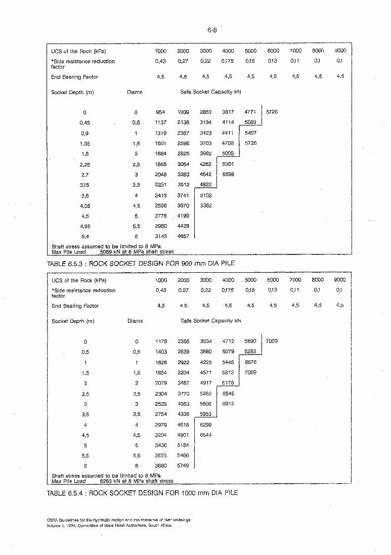
UCS of the Rock (kPa)
*Side resistance reduction factor
End Bearing Factor
Socket Depth (m)
2000 3000 4000 5000
0,27 0,22 0375 035
4,5 43 4,5 4,5
Safe Socket Capacity kN
Shaft stress assumed to be limited to 8 MPa. Max Pile Load 5089 kN at 8 MPa shaft stress
TABLE 6.5.3 : ROCK SOCKE3 DESIGN FOR 900 mm DIA PILE
UCS of the Rock (kPa)
*Side resistance reduction factor
End Bearing Factor
Socket Depth (m) Diams
0
0 3
1
195
2
2,s
3
3,5
4
485
5
5,5
6
Safe Socket Capacity kN
Shaft stress assumed to be limited to 8 MPa Max Pile Load 6283 kN at 8 MPa shaft stress
FOR 1000 mm DIA PILE
CSRA Guidelines for the hydraulic design and maintenance of river cmssings Volume 11, 1994, Cornmitiee of State Road Authorities, South Africa.

UCS of the Pock (kPa)
"Side resistance reduction factor
End Bearing Factor
Socket Depth (m) Diams
1000 2000 3000 4000 5000
0,43 0,27 0,22 0,175 015
4,5 4,5 4,5 45 4,5
Safe Socket Capacity kN
Shaft stress assumed to be limited to 8 MPa Max Pile Load 9048 kN at 8 MPa shaft stress
TABLE 6.5.5 : ROCK OCKET DESIGN FOR 1200 mm DIA PILE
UCS of the Rock (kPa)
*Side resistance reduction factor
End Bearing Factor
Socket Depth (m) Diams
2000 3000 4000
0,27 0,22 0,175
4'5 4,5 4,5
Safe Socket Capacity kN
8588
9256
9924
10592
11260
Shaft stress assumed to be limited to 8 MPa Wax Pile Load l1451 kN at 8 MPa shaft stress
R 1350 mm DIA PIL
CSRA Guidelines for the hydraulic design and maintenance of river crossings Volume 11, 1994, Committee of State Road Authorities, South Africa

UCS of the Rock (kPa)
*Side resistance reduction factor
End Bearing Factor
Socket Depth (m) Diams Safe Socket Capacity kN
Shaft stress assumed to be limited to 8 MPa. Mat Pile Load 14137 kN at 8 MPa shaft stress
Calculate socket depth required to resist a working load of 12000 k is 3000 kPa.
Initially select a 1350 m dia pile. Read down column headed UCS 3000 kPa u read horizontally to 4'5 m or 3 pile diameters. Check
whether a 1200 mm diameter pile will suffice. By following the same procedure it will be fou indicating a shaft stress in excess of 8 MPa will be crossed and a 1200 mm diameter pile will t
suitable.
CSRA Guidelines for the hydiaulic design and maintenance of river crossings Volume 11, 1994, Committee of State Road Authorities, South Africa