Embed Size (px)
Citation preview

Physics Procedia 74 ( 2015 ) 191 – 198
Available online at www.sciencedirect.com
1875-3892 © 2015 The Authors. Published by Elsevier B.V. This is an open access article under the CC BY-NC-ND license (http://creativecommons.org/licenses/by-nc-nd/4.0/).Peer-review under responsibility of the National Research Nuclear University MEPhI (Moscow Engineering Physics Institute)doi: 10.1016/j.phpro.2015.09.187
ScienceDirect
Conference of Fundamental Research and Particle Physics, 18-20 February 2015, Moscow, Russian Federation
The prototype of GAMMA-400 apparatus A.I. Arkhangelskiya,*, I.V. Arkhangelskajaa, M.D. Kheymitsa, M.F. Runtsoa,
S.I. Suchkovb, N.P. Topchievb, Yu.T. Yurkina aNational Research Nuclear University MEPhI (Moscow Engineering Physics Institute), Kashirskoe highway 31, Moscow, 115409, Russia
bP.N. Lebedev Physical institute of the Russian Academy of Sciences, Leninskij Prospekt 53, Moscow, 119991, Russia
Abstract
Scientific project GAMMA-400 (Gamma-Astronomy Multifunction Modules Apparatus) relates to the new generation of space observatories for investigation of cosmic -emission in the energy band from ~20 MeV up to several TeV, electron/positron fluxes from ~1 GeV up to ~10 TeV and cosmic-ray nuclei fluxes with energies up to ~1015 eV by means of GAMMA-400 gamma-telescope represents the core of the scientific complex. The investigation of gamma ray bursts in the energy band of 10 keV–15 MeV are possible too by means of KONUS-FG apparatus included in the complex. For -rays in the energy region from 10 to 100 GeV expected energy resolution changes from ~3% to ~1% and angular resolution from ~0.1% to ~ 0.01% respectively, /protons rejection factor is ~5·105. The GAMMA-400 satellite will be launched at the beginning of the next decade on the high apogee orbit with following initial parameters: apogee altitude ~300000 km, perigee altitude ~500 km, rotation period ~7 days, inclination to the equator plane 51.4º. The active functioning interval will be 7-10 years. The scientific complex will have next main technical parameters: total weight ~4100 kg, power consumption ~2000 W, information quote 100 GByte/day. During the project development, the prototype of apparatus was created for working-off of the main apparatus construction units in laboratory conditions. The main distinctive features of the prototype are presented.
© 2015 The Authors. Published by Elsevier B.V. Peer-review under responsibility of the National Research Nuclear University MEPhI (Moscow Engineering Physics
Institute).
Keywords: electromagnetic calorimeter; gamma-telescope; dark matter; cosmic gamma-ray emission; prototype; space observatory
1. Introduction
Space project GAMMA-400 [1-3] is intended for measurements of characteristics of cosmic gamma-emission in
* Corresponding author. Tel.: +7-495-788-56-99.
E-mail address:[email protected]
© 2015 The Authors. Published by Elsevier B.V. This is an open access article under the CC BY-NC-ND license (http://creativecommons.org/licenses/by-nc-nd/4.0/).Peer-review under responsibility of the National Research Nuclear University MEPhI (Moscow Engineering Physics Institute)

192 A.I. Arkhangelskiy et al. / Physics Procedia 74 ( 2015 ) 191 – 198
the energy band from ~20 MeV up to several TeV, electron/positron fluxes from ~1 GeV up to ~10 TeV and cosmic-ray nuclei fluxes with energies up to ~1015 eV by means of GAMMA-400 gamma-telescope [4-8] represents the core of the scientific complex. Within the framework of this project, which has now expanded internationally, the design and construction of a precision gamma-ray telescope is being carried out. The investigation of gamma ray bursts over virtually the entire celestial sphere in the energy band of 10 keV–15 MeV are possible too by means of KONUS-FG apparatus in simultaneous operation with the GAMMA-400 gamma-telescope. For -rays in the energy region from 10 to 100 GeV expected energy resolution changes from ~3% to ~1% and angular resolution from ~0.1% to ~ 0.01% respectively, /protons rejection factor is ~5·105.
The GAMMA-400 space observatory will be launched on the NAVIGATOR service platform designed by Lavochkin Association at the beginning of the next decade on the high apogee orbit with following initial parameters: apogee altitude ~300000 km, perigee altitude ~500 km, rotation period ~7 days, inclination to the equator plane 51.4º. After approximately half a year the orbit will evolve into an almost circular orbit with radius of ~150000 km, i.e. the observatory will fully leave the Earth’s radiation belts. The expected lifetime will be more then 7 years. The planned scientific complex main technical parameters are: total weight ~4100 kg, power consumption ~2000 W, information quote 100 GByte/day.
Precision investigations of -ray emission from Galactic Center, Crab, Vela, Cygnus, Geminga and other regions will be performed, as well as diffuse -ray emission, along with measurements of high-energy e-/e+ and nuclei fluxes. Furthermore, it will study gamma ray bursts and -ray emission from the Sun during periods of solar activity.
2. GAMMA-400 apparatus structure
GAMMA-400 apparatus can be subdivided into two main parts: GAMMA-400 scientific complex and NAVIGATOR service platform systems directly providing the operation of scientific complex.
GAMMA-400 scientific complex consists of the following systems:
gamma-telescope GAMMA-400 [4-8]; gamma ray burst monitor KONUS-FG (four directional detectors and two spectrometric detectors); two magnetometers (M1, M2) for measuring the magnetic field [9]; two star sensors (SS1, SS2) for determining the GAMMA-400 axes with accuracy of approximately 5", functioning as a more precise double of service platform NAVIGATOR ones; Scientific Complex Telemetry System (SCTS); Scientific Data Acquisition System (SDAS) [10]; Pulse Commands and Power Supply System (PCPSS).
Functional diagram of GAMMA-400 scientific complex including interconnection channels within complex and across it and NAVIGATOR service platform systems is shown at Fig. 1. Gamma-telescope GAMMA-400 represents the core of the scientific complex providing the most part of scientific goals of the project. Its physics scheme is shown at Fig. 2. KONUS-FG, magnetometers, star sensors and SCTS carry out the helper functions. SDAS and PCPSS constitute the scientific service systems providing control and communication between units inside the scientific complex from one hand and scientific complex as a whole and service platform NAVIGATOR systems from the other hand.
The gamma-telescope GAMMA-400 includes following subsystems and detectors:
anticoincidence system (AC: ACtop – top detector and AClat – four lateral detectors AClat1–AClat4) [11]; lateral calorimeter detectors (LD – four detectors LD1–LD4); time-of-flight system (TOF – two detectors S1, S2); scintillation detectors of calorimeter (SDC – two detectors S3, S4); converter-tracker (C – four towers C1–C4); position-sensitive calorimeter (position-sensitive converter-calorimeter CC1, total-absorption calorimeter CC2); neutron detector (ND) [12, 13]; system of triggers and counting signals formation (ST) [14, 15].

A.I. Arkhangelskiy et al. / Physics Procedia 74 ( 2015 ) 191 – 198 193
Fig. 1. Functional diagram of GAMMA-400 apparatus.
Fig. 2. Physical scheme of GAMMA-400 gamma-telescope. All presented dimensions (in mm) are reference.

194 A.I. Arkhangelskiy et al. / Physics Procedia 74 ( 2015 ) 191 – 198
3. The prototype of GAMMA-400 apparatus
The main goal of the prototyping of GAMMA-400 scientific complex was try-out of the construction and information structure of the basic units of the scientific complex systems such as detectors assembly, power supplies, data processing and system control. The choice of suitable electronic component base, taking into account requirements of high reliability and radiation hardness of designed equipment was the very important task too. Of course, the composition of the prototype does not fully conform to the real apparatus and reproduces only main distinctive features of it.
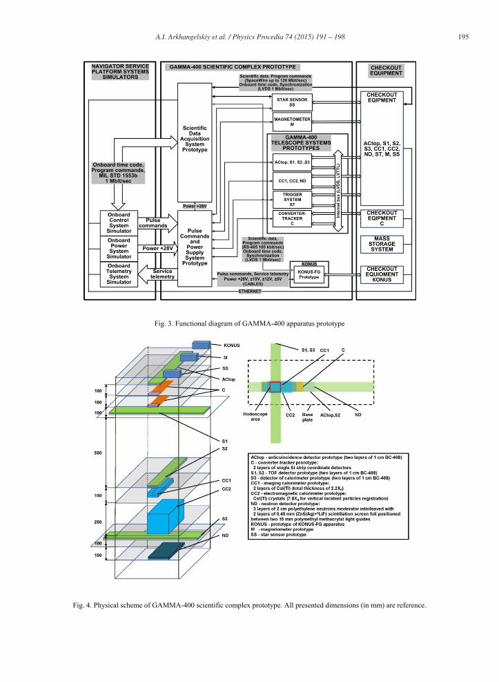
The prototype of GAMMA-400 apparatus can be subdivided into three main parts (see Fig. 3):
the set of NAVIGATOR service platform systems simulators for testing the interfaces between satellite platform and scientific complex including: o onboard control system simulator, providing issue of program commands (16-bit control codes for “thin”
adjustment of scientific measuring systems) and onboard time code (32-bit serial code of event registration moment in UTC) through multiplexed data channel (MIL-STD-1553B) into SDAS prototype. Pulse control commands (either voltage pulse with duration ~0,1 0,3 sec with amplitude equals for satellite power or “dry-contacts” – switch on/switch off) issue is performed too;
o onboard power supply simulator, providing powered of scientific complex prototype and monitoring of energizing circuits parameters during prototype assembly testing;
o onboard telemetry system simulator, providing automatic check of service telemetry parameters; GAMMA-400 scientific complex prototype, including following prototypes: o gamma-telescope GAMMA-400 prototype; o gamma-ray burst monitor KONUS-FG electronics block prototype (made by Ioffe Physical Technical
Institute, St. Petersburg, Russia); o magnetometer (M) prototype (LEMI-038, made by Lviv Centre of Institute for Space Research, Ukraine [16]); o star sensor (SS) information interface simulator; o scientific data acquisition system (SDAS) prototype; o pulse commands and power supply system (PCPSS) prototype; the set of checkout equipment for monitoring the scientific complex functionality and storing testing results. Different checkout equipment devices are interconnected with each other, SDAS prototype and mass storage system by Ethernet 10/100 Mbit/sec interfaces.
The prototype of gamma-telescope GAMMA-400 includes following telescope subsystems prototypes (Fig. 4):
anticoincidence system prototype(AC: ACtop – top detector); time-of-flight system prototype (TOF – two detectors S1, S2); scintillation detector of calorimeter prototype (SDC – one detector S3) [17]; converter-tracker prototype (C – two silicon-strip single coordinate ladders); position-sensitive calorimeter prototype (two detectors CC1, CC2); neutron detector (ND) prototype; system of triggers and counting signals formation (ST) prototype.
The construction of ACtop, TOF and SDC prototypes is similar. Each of them consists of two layers of individual segments with dimensions of 1200x120x10 mm3 for ACtop and 1000x100x10 mm3 for S1-S3 made of polyvinyltoluene scintillator -408. Each segment is viewed from opposite shortest butt-ends by two blocks consists of six silicon photomultipliers (SiPM) SensL MicroFB-60035-SMT mounted on PCB. The signals from SiPM blocks of individual detectors arrive to the set of front-end electronics for subsequent processing in checkout equipment and ST prototype. The pair of detectors ACtop, S2 are oriented perpendicularly relative to another pair S1, S3 forming the hodoscope area of 100x100 mm2 for performing the measurements by means of cosmic muons registration. The distance between TOF detectors S1 and S2 of LTOF=500 mm conforms to the value in the real gamma-telescope configuration for verification of TOF system functionality.
A.I. Arkhangelskiy et al. / Physics Procedia 74 ( 2015 ) 191 – 198 195
Fig. 3. Functional diagram of GAMMA-400 apparatus prototype
Fig. 4. Physical scheme of GAMMA-400 scientific complex prototype. All presented dimensions (in mm) are reference.

196 A.I. Arkhangelskiy et al. / Physics Procedia 74 ( 2015 ) 191 – 198
The converter-tracker (C) prototype (made by Istituto Nazionale di Fisica Nucleare, Italy) consists of two single silicon-strip coordinate ladders. Each ladder is made by 4 single-sided, AC-coupled, 410-μm thick, 95×95 mm2 silicon strip detectors with an implant pitch of 121 μm and a read-out pitch of 242 μm (one floating strip every two read-out strips). The strip bias is via polysilicon resistors of nominal value 40 M . The detectors are fabricated on high-resistivity ( 4 k ·cm), n-doped, 6” silicon wafers by Hamamatsu PK. The silicon detector ladder is read-out by three 128-channels front-end ASICs TAA1, manufactured by Integrated Detector Electronics AS. Each channel features a folded-cascode charge sensitive preamplifier, a CR-RC shaper, a sample-and-hold circuit and a threshold discriminator. The threshold is unique for the 128 channels, with a 3-bit trimming DAC per channel for fine threshold adjustment. The read-out of the channels is via an analog multiplexer with a maximum clock frequency of 10 MHz. The power consumption is around 500 μW/channel. The noise measured for a full ladder is about 1000 e- rms for each channel. The readout sequence is generated by a VME Sequencer (INFN TS made) while an ADC Board provides the analog output digitization with a 12 bit AD9220 chip. The digitized data are sent to a VME Input/Output register that hosts a FPGA responsible of the zero suppression allowing a data taking rate of 1 kHz. The readout system is a standard VME system controlled by a SBS (Bit3) model 620 bridge optically linked to a PC running the Linux operating system. The trigger signal is generated by ST prototype from the hodoscope consists of ACtop and S1-S3 scintillation detectors. The conditioning of the trigger signal is provided by a custom VME board (the trigger board) and the signals are then sent to a VME Control Board to generate the DAQ trigger and the readout sequence; the board is also responsible of the ASICs configuration before the start of the run. The signals of the detector under test are digitized by ADC board and sent to the Control Board.
The position-sensitive calorimeter (CC) prototype consists of two layers of CsI(Tl) scintillation crystals (two crystals in each layer) with dimension of 333×50×20 mm3 (CC1 imaging detector) and a block of sixteen 36×36×430 mm3 CsI(Tl) scintillators (CC2 electromagnetic calorimeter). All scintillators are being viewed by mounted on PCB blocks of four (in CC1) or two (in CC2) silicon photomultipliers SensL MicroFB-60035-SMT from two opposite shortest end-butts of scintillation crystals. The front-end electronics of each SiPM blocks includes special circuits for thermostabilization of SiPM gain. The signals from SiPM blocks of individual crystals are amplified and arrive to the set of base-line restorers, discriminators, analogue multiplexors and analogue to digital converters for subsequent processing by checkout equipment. The energy thresholds for all discriminators and a number of other electronics parameters can be changed by means of control commands from SDAS prototype through SpaceWire channel. Digitized spectral information from position-sensitive calorimeter prototype issues to checkout equipment by means of 100 Mbit/sec LVDS channel. The trigger signal for CC prototype is generated by ST prototype from the hodoscope consists of ACtop and S1-S3 scintillation detectors. Information interface between SDAS and CC prototypes is provided by two PCI-based transceivers - SpaceWire/PCI and LVDS/PCI included in checkout equipment composition.
The neutron detector prototype consists of three layers of 2 cm thick polyethylene neutrons moderator interleaved with two layers of 0.45 mm (ZnS(Ag)+6LiF) scintillation screen foil (manufactured by Scintacor Ltd.) positioned between two 15 mm thick polymethyl methacrylate (PMMA) light guides with dimension of 1000×100 mm2. Total detection module size is 1000×100×120 mm3. All light guides are being viewed by mounted on PCB blocks of ten silicon photomultipliers SensL MicroFB-60035-SMT from two opposite shortest end-butts of light guides. The front-end electronics of each SiPM blocks includes special circuits for thermostabilization of SiPM gain. The signals from SiPM blocks of individual crystals are amplified and arrive to the set of base-line restorers, discriminators and counters for subsequent processing by checkout equipment. The energy thresholds for all discriminators and a number of other electronics parameters can be changed by means of control commands. The temporal profile of neutrons count rate in neutron detector prototype issues to checkout equipment. The trigger signal for ND prototype is generated by ST prototype from the hodoscope consists of ACtop and S1-S3 scintillation detectors. Information interface between SDAS and ND prototypes is provided by SpaceWire/PCI transceiver included in checkout equipment composition.
The system of triggers and counting signals formation (ST) prototype represents the system of program controlled digital delay lines, counters and units for master triggers signals formation from any combination of input digital and analogue pulses. The trigger signals for converter-tracker C, position-sensitive calorimeter CC, scintillation detector of calorimeter SDC and neutron detector ND prototypes are generated by ST prototype from the hodoscope consists of ACtop and S1-S3 scintillation detectors. ST prototype consists of two modules – the

A.I. Arkhangelskiy et al. / Physics Procedia 74 ( 2015 ) 191 – 198 197
trigger board and the control unit. The trigger board represents the FPGA-based program controlled block capable to generate four different trigger signals from any combination of eighth input digital signals simultaneously. In addition, the analogue unit consists of the set of program controlling amplifiers, comparators and multiplexors included in this block for trigger signals formation from up to sixteen analogue signals. The computational core of the ST prototype control unit is the single board industrial processor module Vortex VX86-6042 [18] connected to the trigger board through half size ISA bus. Information interface between SDAS and ND prototypes is provided by Ethernet 10/100 Mbit/sec interface and SpaceWire/PCI transceiver included in checkout equipment composition.
Scientific data acquisition system (SDAS) prototype carries out the following main functions: the data acquisition from measuring systems of scientific complex prototype through two SpaceWire and one RS-485 channels; preliminary data processing of scientific information and storage it in nonvolatile mass memory (4 GByte total); scientific information transfer into mass storage unit through Ethernet 10/100 Mbit/sec interface; control information reception from onboard control system simulator through multiplexed data channel (MIL-STD-1553B), its decoding and transfer into scientific complex prototype; generating onboard time code and synchronization signals for measuring systems of scientific complex prototype. Logical model of SDAS prototype processing module loads in Stratix IV Altera FPGA and fully implements the main real SDAS functionality [10].
Pulse commands and power supply system (PCPSS) prototype consists of program controlled by onboard control system simulator relay switchboard and the set of secondary power supply units permits commutation and powering of scientific complex prototype systems by the set of high-stable voltages of ±5V, ±12V and ±15V converted from +28V of onboard power supply system simulator. PCPSS prototype secondary power supply units utilize MOR2805S, MOR2812S, MCH2815D, FMCE-1528 and FMSA-461 DC/DC converters (Crane Aerospace & Electronics) and providing total electric power of 2000 W.
4. Conclusions
During the GAMMA-project development, the prototype of apparatus was created. Experimental working-off of the main construction units in laboratory conditions has justified the engineering solutions and electronic elemental base selection for design of scientific complex equipment. In particular: common information structure and construction of scientific complex, front-end electronics design for SiPM-based particles detectors circuits, SpaceWire and Serial RapidIO interfaces realization for high-speed information transfer, applicability of selected construction and experimental methods for gamma-telescope tracking system, power and controlling systems design, and so on. The results were obtained on this stage of project have allowed to proceed to the next stages of GAMMA-400 scientific complex design and preparation.
References
[1]Topchiev N.P., Galper A.M., Bonvicini V. et al. The GAMMA-400 experiment: Status and prospects. Bull. Russ. Acad. Sci. Phys. 2015;79(3):417–420.
[2]Galper A.M., Adriani O., Arkhangelskaja I.V. et al. Status of the GAMMA-400. Advances in Space Research 2013; 51:297-300. [3]Galper . ., Arkhangelskaja I.V., Arkhangelskiy A.I. et al. Space gamma-observatory GAMMA-400: current status and perspectives.
Physics Procedia. 2015; This procedia volume. [4]Galper A.M., Adriani O., Aptekar R.L. et al. Characteristics of the GAMMA400 Gamma-Ray Telescope for Searching for Dark Matter
Signatures. Bull. Russ. Acad. Sci. Phys. 2013;77(11):1339–1342. [5]Galper A.M., Adriani O., Aptekar R.L. et al. Design and performance of the GAMMA-400 gamma-ray telescope for dark matter searches. AIP
Conf. Proc. 2013;1516: 288-292. [6]Ginzburg V.L., Kaplin V.A., Runtso M.F. et al. Advanced GAMMA-400 -ray telescope for recording cosmic -rays with energies up to 3
TeV. Bull. Russ. Acad. Sci. Phys. 2009;73(5):664-666. [7]Leonov . ., Galper . ., Arkhangelskaja I.V. et al. Physical performance of the GAMMA-400 gamma-ray telescope. Angular resolution,
proton and electron separation. Physics Procedia. 2015; This procedia volume. [8]Kheymits M.D., Arkhangelskaja I.V., Arkhangelskiy A.I. et al. Method to reconstruct incident low-energy gamma-ray direction in GAMMA-
400 gamma-ray space telescope. Physics Procedia. 2015; This procedia volume. [9]Khyzhniak E.V., Arkhangelskaja I.V., Chasovikov E.N. et al. Magnetometer application for GAMMA-400 telescope switching into the mode
with increased low energy charged particles intensity registration. Physics Procedia. 2015; This procedia volume. [10]Bobkov S.G., Serdin O.V., Arkhangelskiy A.I. et al. The unification of space qualified integrated circuits by example of international space
project GAMMA-400. Physics Procedia. 2015; This procedia volume.

198 A.I. Arkhangelskiy et al. / Physics Procedia 74 ( 2015 ) 191 – 198
[11]Runtso .F, Arkhangelskiy A.I, Arkhangelskaja I.V et al. The distinctive features of anticoincidence detector system of the GAMMA-400 gamma-ray telescope. Physics Procedia. 2015; This procedia volume.
[12]Gnezdilov I.I., Dedenko G.I., Ibragimov R.F. et al. Optimization of the neutron detector design based on the 6LiF/ZnS(Ag) scintillation screens for the GAMMA-400 space observatory. Physics Procedia. 2015; This procedia volume.
[13]Gnezdilov I.I., Mukhin V.I.. The distribution of neutron absorbing time in the neutron detector of the GAMMA-400 space observatory. Physics Procedia. 2015; This procedia volume.
[14]Arkhangelskaja I.V., Arkhangelskiy A.I., Chasovikov E.N. et al. The system of counting and triggers signals formation for gamma-telescope GAMMA 400. Physics Procedia. 2015; This procedia volume.
[15]Arkhangelskaja I.V., Murchenko A.E., Chasovikov E.N. et al. Gamma-telescopes Fermi/LAT and GAMMA-400 trigger systems event recognizing methods comparison. Physics Procedia. 2015; This procedia volume.
[16]http://www.isr.lviv.ua. [17]Naumov P.P., Naumov P.Yu., Runtso M.F. et al. Software for control and measuring instrumentation of GAMMA-400 gamma-telescope fast
scintillator detector system. Physics Procedia. 2015; This procedia volume. [18]VX86-6042: Embedded Half-SizeVortex86™ AIO SBC Manual No. IUM6042000-01 Ver.1.2 Rev. 4. ICOP Technology Inc. 2006.