Embed Size (px)
Citation preview
ISSN 2572-4975 (Print), 2572-4991 (Online)
325
The properties of bolted joint assembly with contact
stiffness
Bowen Hou, Yadong Sun, Wei Sun, Wei Zhang*1
School of Mechanical Engineering, Dalian University of Technology,Dalian 116024 PR China
Abstract: In this paper, the real surface bolt connection model considering the
contact characteristics of the joint surface is established by using the finite
element simulation method. There is a non-linear segment in the initial stage of
the angular preload curve. Flange model and two bolts mutual model under real
contact surface are established. The contact characteristics of the joint surface
will enhance the influence of bolt interaction. Considering comprehensively,
cross tightening is the most suitable method in Wheel Disk Connection Structure.
Keywords: Threaded Fasteners; Contact stiffness; Torque-angle tightening;
finite element analysis; Bolt interaction; Tightening sequence;
1 Introduction
As a critical basic component, bolt plays a crucial role in the mechanical industry.
The advantages of bolt connection are simple structure, reliable connection, convenient
assembly and so on. With the development of science and technology, mechanical
equipment is developing towards precision, complexity and intelligence, and the
accuracy of bolt assembly is also improved. The quality of bolt connection assembly
has an important influence on the key performances of assembly component especially
disk structures such as the dynamic stiffness dispersion, structural stability and
durability. The improper assembly of disc bolts or excessive dispersion of preload will
lead to poor neutrality, deviation of centroid line and asymmetry of radial stiffness of
the disc, which will lead to excessive vibration of the whole machine and high cycle
Corresponding author([email protected])
International Journal of Smart Engineering, Volume 2, Issue 4, 2018
ISSN 2572-4975 (Print), 2572-4991 (Online)
326
fatigue of the connecting components during the operation of the equipment, thus
reducing the safety and reliability of the equipment. [1-7]
The uniformity of wheel disc bolt load is mainly determined by two factors: one is
the accuracy of tightening preload of single bolt, the other is the influence of loading
bolt between the former and the latter during sequential loading process, that is the
elastic interaction of both bolts. The contact characteristics of the joint surface will
affect the stiffness of the joint surface, so the above factors will affect the uniformity of
the bolt load at the same time. Greenwood [8] et al. put forward the stress-deformation
relationship of the surface micro-convex body by studying the micro-contact
mechanism of the interface. Nassar [9] et al. studied the influence of bolt stiffness and
connector stiffness on the single bolt torque angle method, but did not consider the
contact stiffness caused by the contact characteristics of the joint. FUKUOKA [10]
studied the stiffness of bolted connections under real contact surfaces, but only
considered the contact stiffness between the connectors. In 1969, Campen [11] first
proposed that subsequent loading bolts would change the loads of loaded bolts, that is,
there was elastic interaction between bolts. Bibel [12] proposed that the elastic
interaction was affected by flange size, joint and gasket stiffness, bolt number, bolt size
and length, and tightening method and sequence. Bouzid [13] et al. proposed an elastic
interaction model, in which the stiffness of gaskets and bolts was increased, which was
verified by finite element analysis. But they did not consider the contact stiffness of the
joint when they studied the elastic interaction of bolts.
In this paper, the theoretical model of contact stiffness of the joint surface is
established according to the contact characteristics of the joint surface. The real surface
bolt connection model considering the contact characteristics of the joint surface is
established by using the finite element simulation method. At the same time, the ideal
surface bolt connection model without considering the contact characteristics of the
joint surface is established as a comparison. The tightening effect of the contact
characteristics of the joint surface on the bolt torque method and the torque angle
method is studied. The influence of process and contact characteristics of joint surface
on the elastic interaction of two adjacent bolts. By establishing the six-bolt flange model
of real contact surface, the dispersion of pretension force, the deformation relationship
and neutrality of the connecting parts of the disc bolt connection structure under
different tightening orders are studied.
International Journal of Smart Engineering, Volume 2, Issue 4, 2018
ISSN 2572-4975 (Print), 2572-4991 (Online)
327
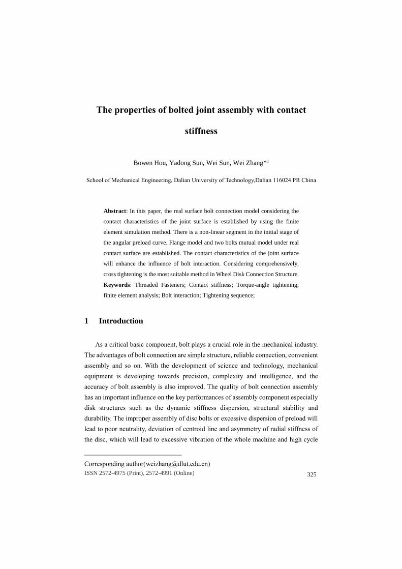
2 Contact stiffness model of bolted joints
Figure 1 Relation between Contact Stress of joint Surface and Deformation of Micro-convex
Body
The contact stiffness of the interface is caused by the elastic-plastic deformation of
the micro-convex body on the contact surface under the action of contact force. As
shown in the red line of Fig. 1, the contact stiffness of the joint surface is formed by
contact and mosaic of the micro-convex body of the joint surface. When the contact
stress reaches the critical stress, the deformation of the micro-convex body increases
slowly and tends to be stable. The relationship between contact stress and deformation
of micro-convex body is shown in Fig. 1.
International Journal of Smart Engineering, Volume 2, Issue 4, 2018
ISSN 2572-4975 (Print), 2572-4991 (Online)
328
The joint of bolted connection structure consists of two parts: the support joint of the
connector and the thread joint. The contact stiffness of the joint has a very significant
influence on the tightening process and the clamping force of the assembly. The contact
stiffness of the interface can be defined as:
𝐾 =𝐹
𝜁
Where F is the applied pretension force and 𝜁 is the deformation of the interface. As
shown in Figure 1, when the contact stress is less than the critical stress, it can be
defined as:
𝜁 = c𝑝𝑚
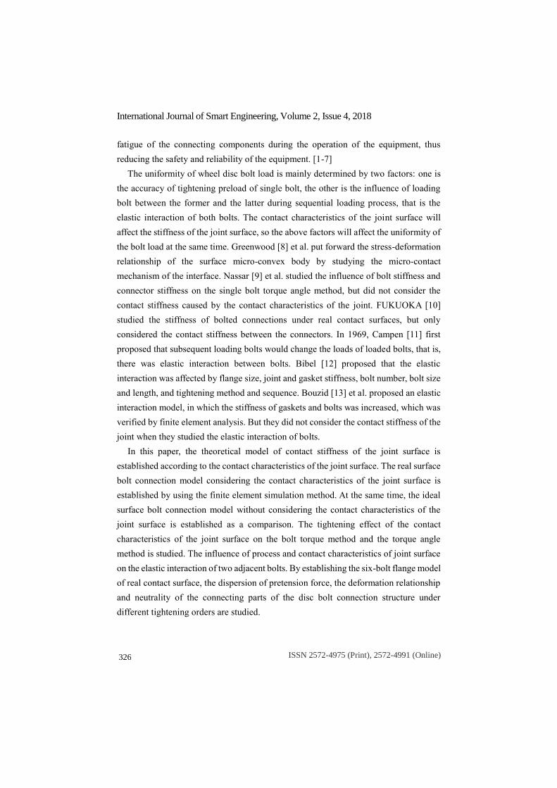
where p is the pressure of the interface, c and m are the fitting coefficients of the
pressure and deformation of the interface, which are determined by the surface
roughness of the interface. According to the experimental study of TANIGUCHI [14],
the variation of c and m with the surface roughness is shown in Fig. 2, which can be
expressed as follows:
c = 0.0674𝑅𝑚𝑡 + 0.413
m = 0.0155𝑅𝑚𝑡 + 0.155
Figure 2 Fitting Coefficient of Pressure Deformation
Taking a rotor bolt connection structure as an example, the roughness of bolt head
contact surface is 𝑅𝑎 1.6, converted into 𝑅𝑧standard roughness of 6.3 μm, the surface
roughness of the other side joints is 𝑅𝑎 3.2, converted into 𝑅𝑧 standard roughness of
12.5 μm , the total roughness of 18.8 μm , so 𝑅𝑚𝑡 = 18.8μm , can be calculated as
follows:
During the tightening process, the average stress of the bolt head under the initial
preload is as follows:
International Journal of Smart Engineering, Volume 2, Issue 4, 2018
ISSN 2572-4975 (Print), 2572-4991 (Online)
329
𝑝ℎ𝑑 =4𝐹𝑠
𝜋(𝐵2 − 𝐷𝑖2)
= 80.48MPa
Therefore, the initial deformation 𝜁𝑠 is calculated as follows:
𝜁𝑠 = c𝑝ℎ𝑑𝑚 = 0.0119μm
During the tightening process, the average stress of the bolt head under the target
clamping force is:
𝑝ℎ𝑑 =4𝐹
𝜋(𝐵2 − 𝐷𝑖2)
= 203.90MPa
The calculation of final deformation ζ
𝜁 = c𝑝ℎ𝑑𝑚 = 0.0180μm
Therefore, the contact surface stiffness of bolt head:
𝑘ℎ𝑑 =𝐹 − 𝐹𝑠
𝜁 − 𝜁𝑠
× 1000 = 3.7537e6 N/mm
Similarly, the surface roughness of bolt threads is 𝑅𝑎 0.8, converted into 𝑅𝑧
standard roughness of 6.3 μm, the surface roughness of the other side joints is 𝑅𝑎
1.6, converted into 𝑅𝑧standard roughness of 6.3 μm, the sum of total roughness is 12.6
μm.
Thread contact surface stiffness:
𝑘ℎ𝑑 = 4.5401e6 N/mm
According to the above principle, in order to realize the simulation analysis
considering contact characteristics, the real contact surface modeling can use the known
mechanical properties of the real contact surface to cut a thin layer on the joint surface
of the model and endow it with approximate properties as an alternative material. The
scale of the micro-convex body on the contact surface is Micro nano scale and the
model size is millimeter. The mesh of the contact surface must be fine enough to obtain
the real surface characteristics. The mechanical properties of the micro-convex body
have been referred by many literatures. Therefore, the contact characteristics can be
simulated by the Multilinear Isotropic Hardening method. This method is suitable for
material in plastic stage, when the stress-strain curve is non-linear. At this time, the
deformation of the micro-convex body is regarded as plastic deformation. For the
surface roughness, 25 μm is chosen, the critical surface pressure is 10 MPa, and the A
value is 10 nm. The relationship between the deformation and stress of the material is
as follows
𝛿 = 2.0980𝑝0.5(𝑝 < 𝑝𝑐)
𝛿 = 0.01𝑝 + 7.3163(𝑝 ≥ 𝑝𝑐)
International Journal of Smart Engineering, Volume 2, Issue 4, 2018
ISSN 2572-4975 (Print), 2572-4991 (Online)
330
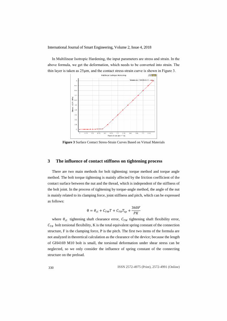
In Multilinear Isotropic Hardening, the input parameters are stress and strain. In the
above formula, we get the deformation, which needs to be converted into strain. The
thin layer is taken as 25μm, and the contact stress-strain curve is shown in Figure 3.
Figure 3 Surface Contact Stress-Strain Curves Based on Virtual Materials
3 The influence of contact stiffness on tightening process
There are two main methods for bolt tightening: torque method and torque angle
method. The bolt torque tightening is mainly affected by the friction coefficient of the
contact surface between the nut and the thread, which is independent of the stiffness of
the bolt joint. In the process of tightening by torque-angle method, the angle of the nut
is mainly related to its clamping force, joint stiffness and pitch, which can be expressed
as follows:
θ = 𝜃𝑐𝑙 + 𝐶𝑇𝑀𝑇 + 𝐶𝑇𝐵𝑇𝑡𝑝 +360𝐹
𝑃𝐾
where 𝜃𝑐𝑙 tightening shaft clearance error, 𝐶𝑇𝑀 tightening shaft flexibility error,
𝐶𝑇𝐵 bolt torsional flexibility, K is the total equivalent spring constant of the connection
structure, F is the clamping force, P is the pitch. The first two items of the formula are
not analyzed in theoretical calculation as the clearance of the device; because the length
of GH4169 M10 bolt is small, the torsional deformation under shear stress can be
neglected, so we only consider the influence of spring constant of the connecting
structure on the preload.
International Journal of Smart Engineering, Volume 2, Issue 4, 2018
ISSN 2572-4975 (Print), 2572-4991 (Online)
331
Assuming that the whole connecting system is connected in series with several
springs, the equivalent total spring coefficient can be expressed as:
1
𝐾=
1
𝐾𝐵
+1
𝐾𝐶
+1
𝐾𝑇𝐻
+1
𝐾𝑚𝑡ℎ𝑑
+1
𝐾𝑚𝑡𝑡ℎ
+1
𝐾𝑚𝑡𝑐
+1
𝐾𝑚𝑡𝑛
where 𝐾𝐵 is the spring constant of the bolt, 𝐾𝐶 is the spring constant of the
connecting part, 𝐾𝑇𝐻 is the spring constant of the thread pair.
𝐾𝑚𝑡ℎ𝑑,𝐾𝑚𝑡𝑡ℎ,𝐾𝑚𝑡𝑐,𝐾𝑚𝑡𝑛 are the contact stiffness of the bolt head joint, the thread
joint, the connecting part joint and the nut end joint respectively.
There are two factors affecting the non-linear section of tightening by torque-angle
method: 1. the surface roughness of the joints; 2. the non-linearity of stress and strain
on the real contact surface. In order to study the relationship between contact stiffness
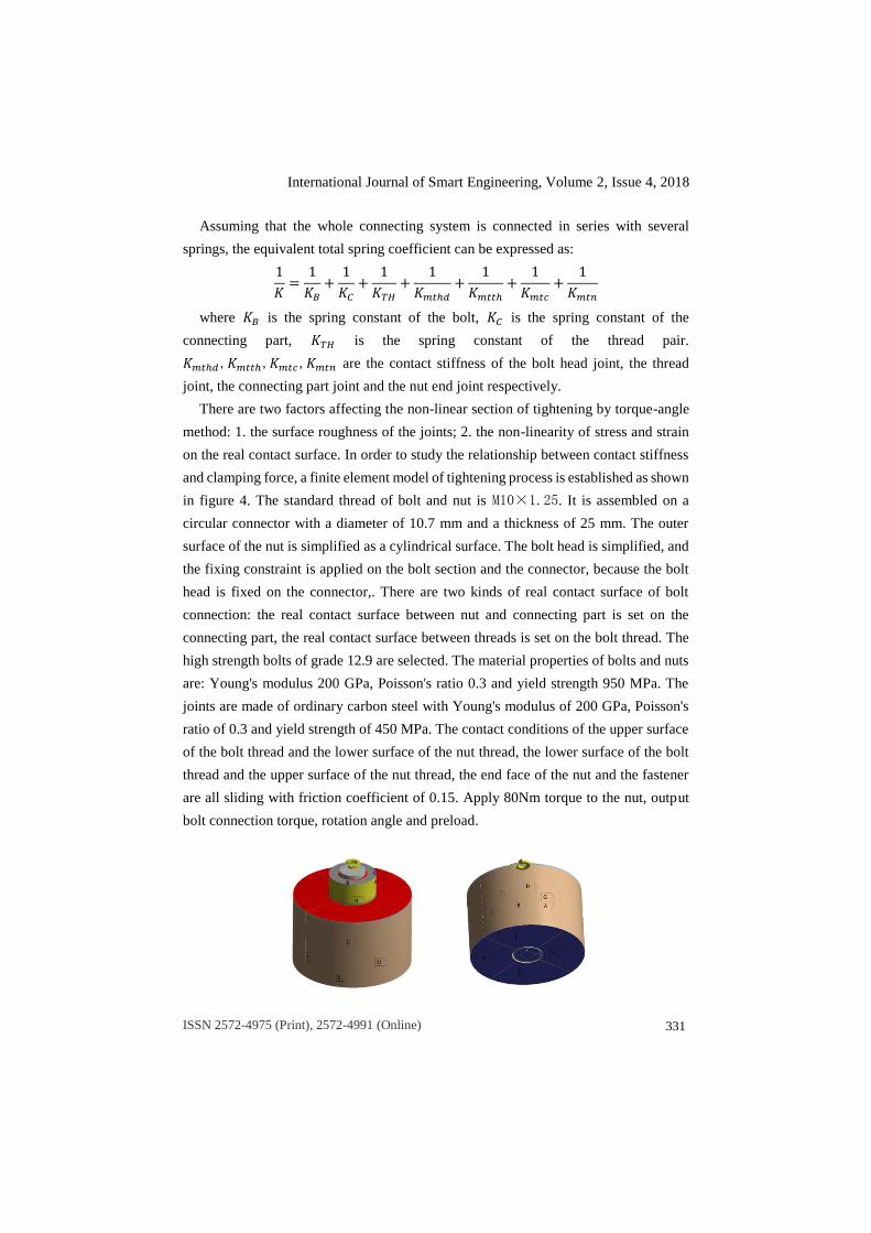
and clamping force, a finite element model of tightening process is established as shown
in figure 4. The standard thread of bolt and nut is M10×1.25. It is assembled on a
circular connector with a diameter of 10.7 mm and a thickness of 25 mm. The outer
surface of the nut is simplified as a cylindrical surface. The bolt head is simplified, and
the fixing constraint is applied on the bolt section and the connector, because the bolt
head is fixed on the connector,. There are two kinds of real contact surface of bolt
connection: the real contact surface between nut and connecting part is set on the
connecting part, the real contact surface between threads is set on the bolt thread. The
high strength bolts of grade 12.9 are selected. The material properties of bolts and nuts
are: Young's modulus 200 GPa, Poisson's ratio 0.3 and yield strength 950 MPa. The
joints are made of ordinary carbon steel with Young's modulus of 200 GPa, Poisson's
ratio of 0.3 and yield strength of 450 MPa. The contact conditions of the upper surface
of the bolt thread and the lower surface of the nut thread, the lower surface of the bolt
thread and the upper surface of the nut thread, the end face of the nut and the fastener
are all sliding with friction coefficient of 0.15. Apply 80Nm torque to the nut, output
bolt connection torque, rotation angle and preload.
International Journal of Smart Engineering, Volume 2, Issue 4, 2018
ISSN 2572-4975 (Print), 2572-4991 (Online)
332
Figure 4 Finite Element Model for Tightening Process of Bolted Connections
Considering Real Contact Characteristics
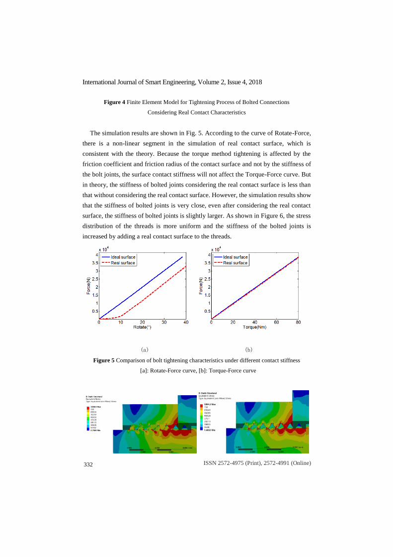
The simulation results are shown in Fig. 5. According to the curve of Rotate-Force,
there is a non-linear segment in the simulation of real contact surface, which is
consistent with the theory. Because the torque method tightening is affected by the
friction coefficient and friction radius of the contact surface and not by the stiffness of
the bolt joints, the surface contact stiffness will not affect the Torque-Force curve. But
in theory, the stiffness of bolted joints considering the real contact surface is less than
that without considering the real contact surface. However, the simulation results show
that the stiffness of bolted joints is very close, even after considering the real contact
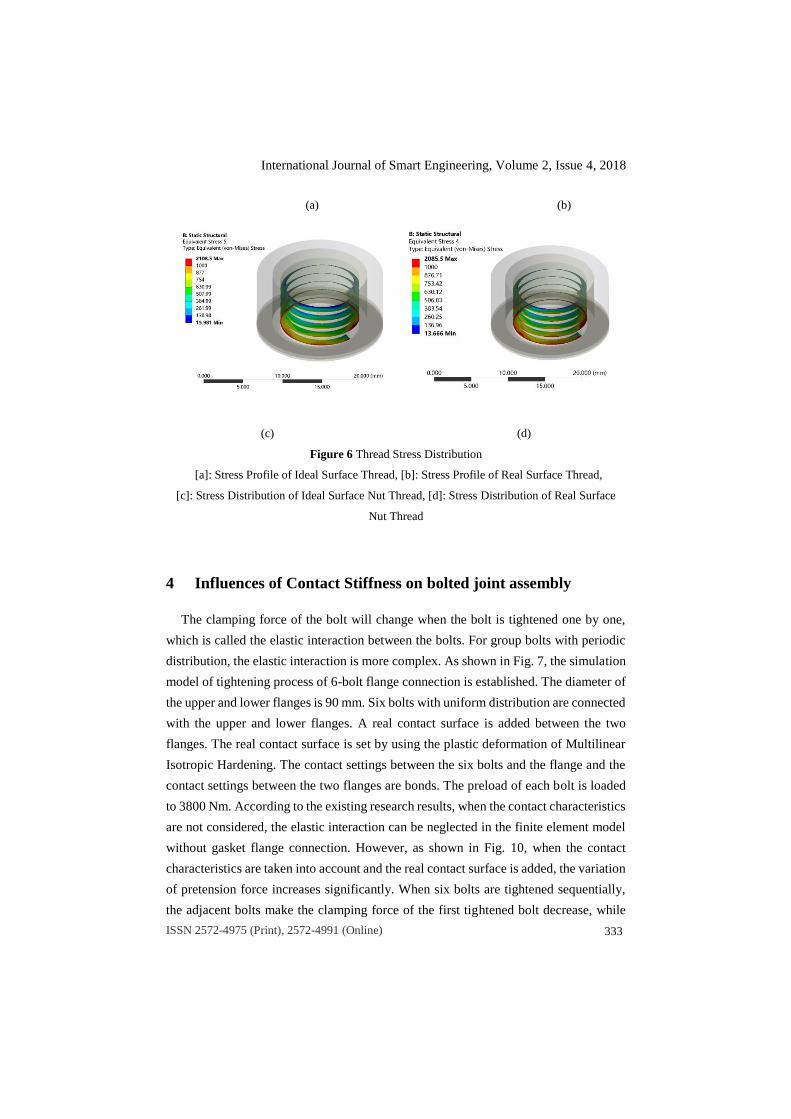
surface, the stiffness of bolted joints is slightly larger. As shown in Figure 6, the stress
distribution of the threads is more uniform and the stiffness of the bolted joints is
increased by adding a real contact surface to the threads.
(a) (b)
Figure 5 Comparison of bolt tightening characteristics under different contact stiffness
[a]: Rotate-Force curve, [b]: Torque-Force curve
International Journal of Smart Engineering, Volume 2, Issue 4, 2018
ISSN 2572-4975 (Print), 2572-4991 (Online)
333
(a) (b)
(c) (d)
Figure 6 Thread Stress Distribution
[a]: Stress Profile of Ideal Surface Thread, [b]: Stress Profile of Real Surface Thread,
[c]: Stress Distribution of Ideal Surface Nut Thread, [d]: Stress Distribution of Real Surface
Nut Thread
4 Influences of Contact Stiffness on bolted joint assembly
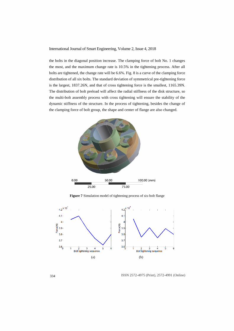
The clamping force of the bolt will change when the bolt is tightened one by one,
which is called the elastic interaction between the bolts. For group bolts with periodic
distribution, the elastic interaction is more complex. As shown in Fig. 7, the simulation
model of tightening process of 6-bolt flange connection is established. The diameter of
the upper and lower flanges is 90 mm. Six bolts with uniform distribution are connected
with the upper and lower flanges. A real contact surface is added between the two
flanges. The real contact surface is set by using the plastic deformation of Multilinear
Isotropic Hardening. The contact settings between the six bolts and the flange and the
contact settings between the two flanges are bonds. The preload of each bolt is loaded
to 3800 Nm. According to the existing research results, when the contact characteristics
are not considered, the elastic interaction can be neglected in the finite element model
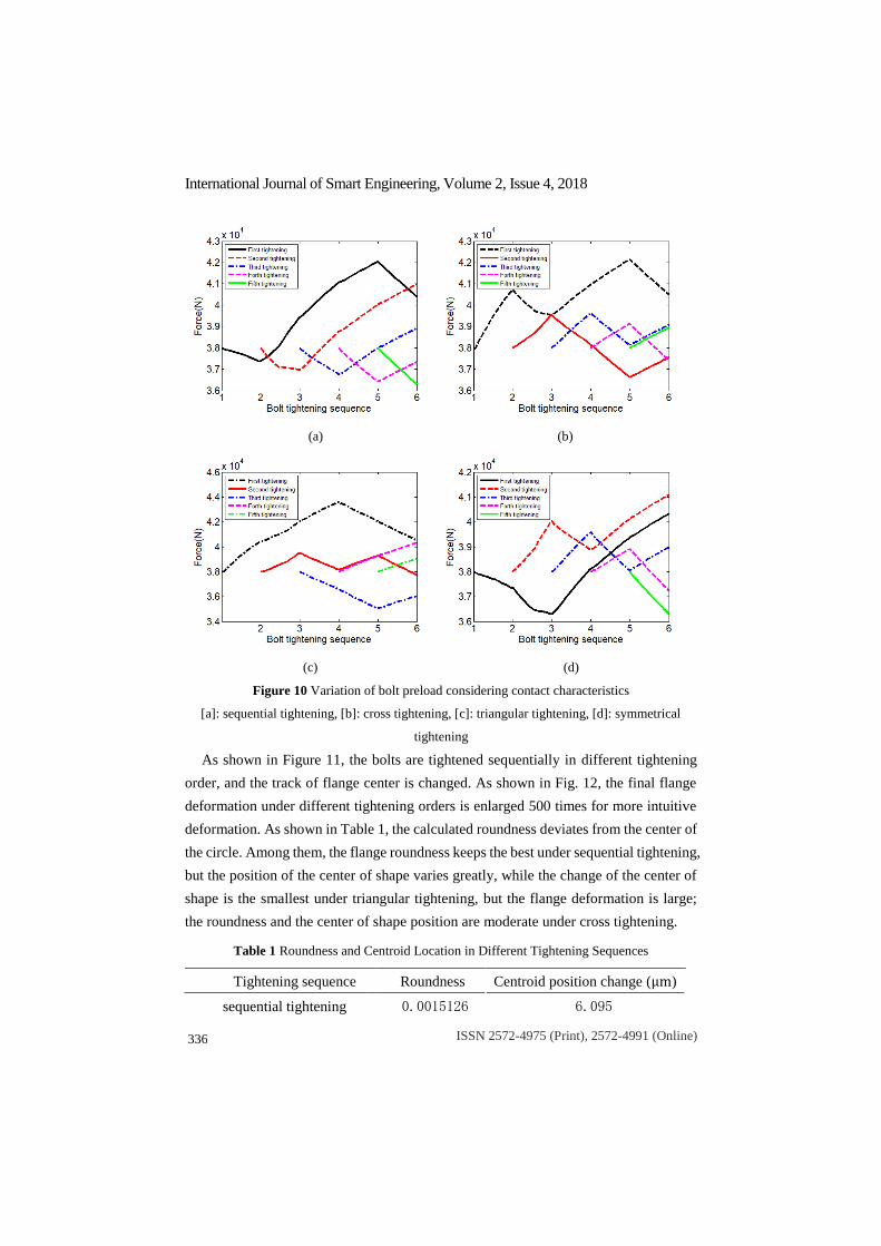
without gasket flange connection. However, as shown in Fig. 10, when the contact
characteristics are taken into account and the real contact surface is added, the variation
of pretension force increases significantly. When six bolts are tightened sequentially,
the adjacent bolts make the clamping force of the first tightened bolt decrease, while
International Journal of Smart Engineering, Volume 2, Issue 4, 2018
ISSN 2572-4975 (Print), 2572-4991 (Online)
334
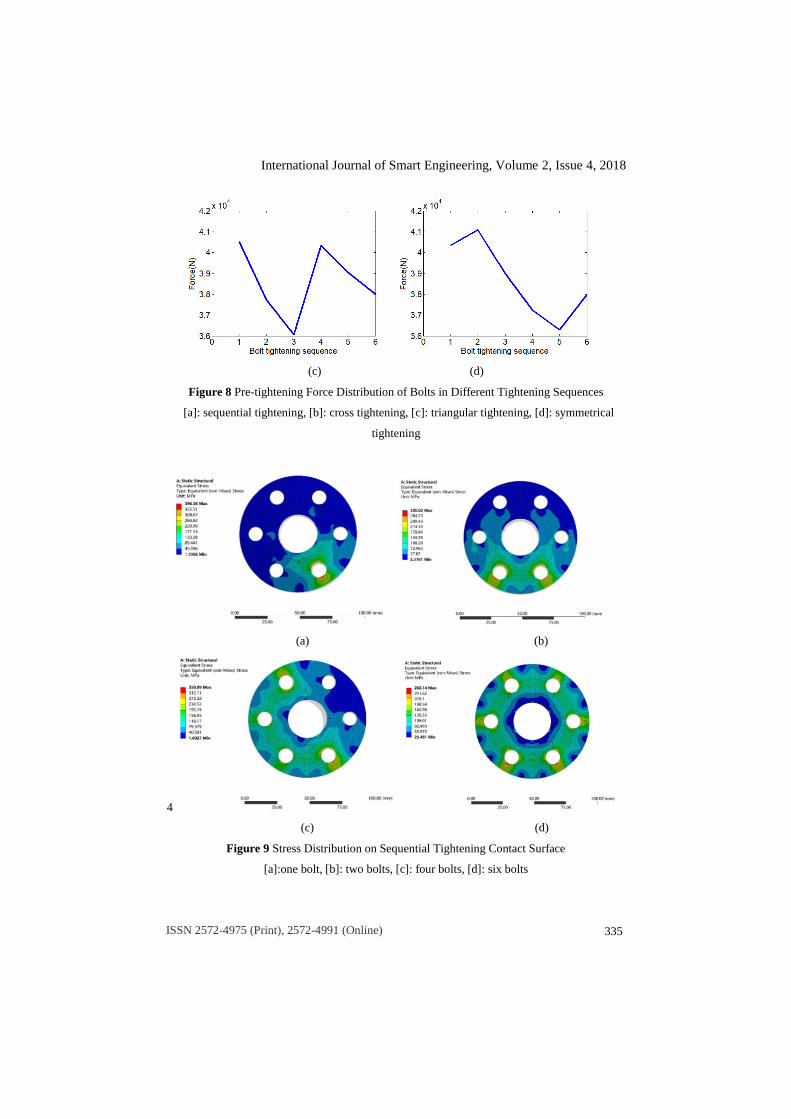
the bolts in the diagonal position increase. The clamping force of bolt No. 1 changes
the most, and the maximum change rate is 10.5% in the tightening process. After all
bolts are tightened, the change rate will be 6.6%. Fig. 8 is a curve of the clamping force
distribution of all six bolts. The standard deviation of symmetrical pre-tightening force
is the largest, 1837.26N, and that of cross tightening force is the smallest, 1165.39N.
The distribution of bolt preload will affect the radial stiffness of the disk structure, so
the multi-bolt assembly process with cross tightening will ensure the stability of the
dynamic stiffness of the structure. In the process of tightening, besides the change of
the clamping force of bolt group, the shape and center of flange are also changed.
Figure 7 Simulation model of tightening process of six-bolt flange
(a) (b)
International Journal of Smart Engineering, Volume 2, Issue 4, 2018
ISSN 2572-4975 (Print), 2572-4991 (Online)
335
(c) (d)
Figure 8 Pre-tightening Force Distribution of Bolts in Different Tightening Sequences
[a]: sequential tightening, [b]: cross tightening, [c]: triangular tightening, [d]: symmetrical
tightening
(a) (b)
4
(c) (d)
Figure 9 Stress Distribution on Sequential Tightening Contact Surface
[a]:one bolt, [b]: two bolts, [c]: four bolts, [d]: six bolts
International Journal of Smart Engineering, Volume 2, Issue 4, 2018
ISSN 2572-4975 (Print), 2572-4991 (Online)
336
(a) (b)
(c) (d)
Figure 10 Variation of bolt preload considering contact characteristics
[a]: sequential tightening, [b]: cross tightening, [c]: triangular tightening, [d]: symmetrical
tightening
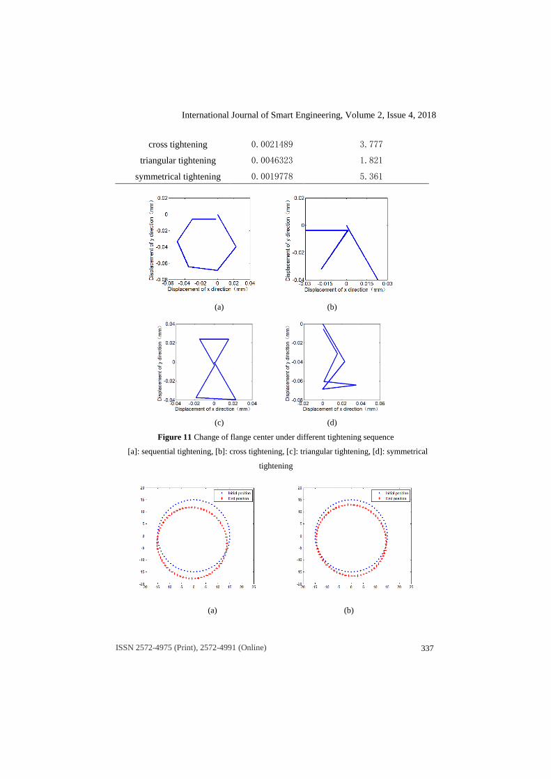
As shown in Figure 11, the bolts are tightened sequentially in different tightening
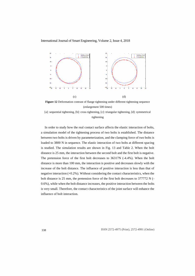
order, and the track of flange center is changed. As shown in Fig. 12, the final flange
deformation under different tightening orders is enlarged 500 times for more intuitive
deformation. As shown in Table 1, the calculated roundness deviates from the center of
the circle. Among them, the flange roundness keeps the best under sequential tightening,
but the position of the center of shape varies greatly, while the change of the center of
shape is the smallest under triangular tightening, but the flange deformation is large;
the roundness and the center of shape position are moderate under cross tightening.
Table 1 Roundness and Centroid Location in Different Tightening Sequences
Tightening sequence Roundness Centroid position change (μm)
sequential tightening 0.0015126 6.095
International Journal of Smart Engineering, Volume 2, Issue 4, 2018
ISSN 2572-4975 (Print), 2572-4991 (Online)
337
cross tightening 0.0021489 3.777
triangular tightening 0.0046323 1.821
symmetrical tightening 0.0019778 5.361
(a) (b)
(c) (d)
Figure 11 Change of flange center under different tightening sequence
[a]: sequential tightening, [b]: cross tightening, [c]: triangular tightening, [d]: symmetrical
tightening
(a) (b)
International Journal of Smart Engineering, Volume 2, Issue 4, 2018
ISSN 2572-4975 (Print), 2572-4991 (Online)
338
(c) (d)
Figure 12 Deformation contrast of flange tightening under different tightening sequence
(enlargement 500 times)
[a]: sequential tightening, [b]: cross tightening, [c]: triangular tightening, [d]: symmetrical
tightening
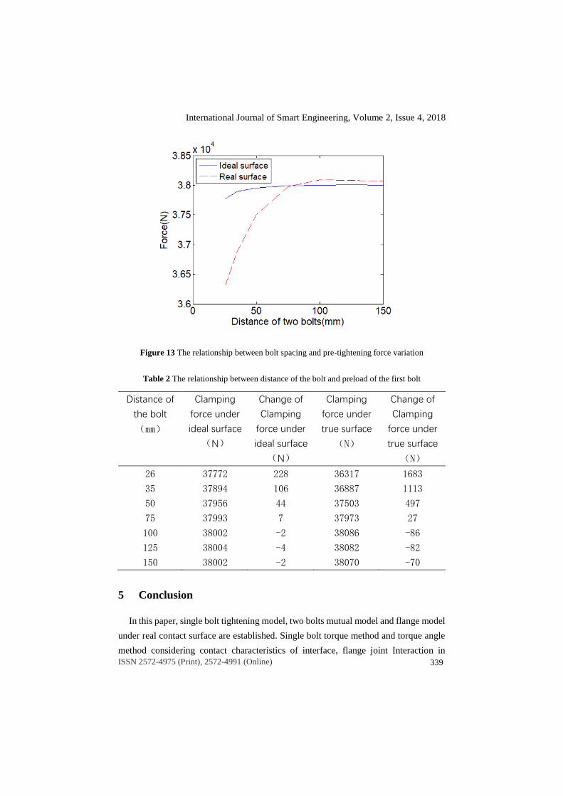
In order to study how the real contact surface affects the elastic interaction of bolts,
a simulation model of the tightening process of two bolts is established. The distance
between two bolts is driven by parameterization, and the clamping force of two bolts is
loaded to 3800 N in sequence. The elastic interaction of two bolts at different spacing
is studied. The simulation results are shown in Fig. 13 and Table 2. When the bolt
distance is 25 mm, the interaction between the second bolt and the first bolt is negative.
The pretension force of the first bolt decreases to 36317N (-4.4%). When the bolt
distance is more than 100 mm, the interaction is positive and decreases slowly with the
increase of the bolt distance. The influence of positive interaction is less than that of
negative interaction (+0.2%). Without considering the contact characteristics, when the
bolt distance is 25 mm, the pretension force of the first bolt decreases to 377772 N (-
0.6%), while when the bolt distance increases, the positive interaction between the bolts
is very small. Therefore, the contact characteristics of the joint surface will enhance the
influence of bolt interaction.
International Journal of Smart Engineering, Volume 2, Issue 4, 2018
ISSN 2572-4975 (Print), 2572-4991 (Online)
339
Figure 13 The relationship between bolt spacing and pre-tightening force variation
Table 2 The relationship between distance of the bolt and preload of the first bolt
Distance of
the bolt
(mm)
Clamping
force under
ideal surface
(N)
Change of
Clamping
force under
ideal surface
(N)
Clamping
force under
true surface
(N)
Change of
Clamping
force under
true surface
(N)
26 37772 228 36317 1683
35 37894 106 36887 1113
50 37956 44 37503 497
75 37993 7 37973 27
100 38002 -2 38086 -86
125 38004 -4 38082 -82
150 38002 -2 38070 -70
5 Conclusion
In this paper, single bolt tightening model, two bolts mutual model and flange model
under real contact surface are established. Single bolt torque method and torque angle
method considering contact characteristics of interface, flange joint Interaction in
International Journal of Smart Engineering, Volume 2, Issue 4, 2018
ISSN 2572-4975 (Print), 2572-4991 (Online)
340
Different Tightening Sequences are studied. The conclusions are summarized as
follows:
(1) Through the stress-deformation relationship of the micro-convex body on the
contact surface, the stiffness of the contact surface is studied Taking a bolt from a rotor
as an example, the standard roughness of the contact surface of the bolt head is 12.5
micron, the standard stiffness of the contact surface of the bolt head is 3.7537e6N/mm,
the standard roughness of the surface of the bolt thread is 6.3 micron, and the stiffness
of the contact surface of the bolt head is 4.5401e6N/mm.
(2) In the process of tightening single bolt by torque-angle method, due to the contact
stiffness of the contact surface, there is a non-linear segment in the initial stage of the
angular preload curve, while the torque method tightening is affected by the friction
coefficient of the contact surface, so the contact stiffness has little effect on the torque
preload curve. Under the real contact surface, the stress distribution of bolt thread is
more uniform than that of ideal surface.
(3). The different tightening sequence of flange bolts will affect the uniformity of
clamping force and assembly accuracy. Among them, the centroid offset of sequential
tightening is the largest, offset is 6.1 μm , but flange deformation is the smallest,
roundness is 0.0015. The centroid offset of triangular tightening is the smallest, offset
is 3.8 μm, but flange deformation is the largest, roundness is 0.0045. The standard
deviation of discrete value of symmetrical tightening preload is the largest, 1837.26N,
and that of cross tightening preload is the smallest, 1165.39N. Considering
comprehensively, cross tightening is the most suitable method in Wheel Disk
Connection Structure.
(4). The contact characteristics of the joint surface will enhance the influence of bolt
interaction. Considering the contact characteristics of the joint surface, when the bolt
distance is 25 mm, the negative interaction occurs. The preload of the first bolt
decreases to 36317 N (-4.4%), while the positive interaction occurs when the bolt
distance is more than 100 mm. The preload of the first bolt increases to 38086 (+0.2%).
In this paper, the influence of contact characteristics of joint surface on assembly
accuracy of bolt connection is discussed from two aspects of single bolt tightening and
bolt interaction. In practical engineering applications, there is no absolutely smooth
ideal surface, so we should consider the effect of the contact stiffness of the real contact
surface. Contact stiffness will make the first half of the angular preload curve of single
bolt tighten appear non-linear, but has little effect on the torque preload curve. This is
also because we will not tighten the bolt by angle method alone in engineering
International Journal of Smart Engineering, Volume 2, Issue 4, 2018
ISSN 2572-4975 (Print), 2572-4991 (Online)
341
application, but by torque-angle method. Contact stiffness will enhance the elastic
interaction between bolts, so in the bolt tightening of Wheel Disk Connection Structure,
tightening order determines the accuracy of assembly. Cross tightening method is
recommended to achieve the balance of assembly stiffness and accuracy.
6 Acknowledgement
The research is supported by National Natural Science Foundation of China (Grant
No. 51605074 and Grant No. 51605072), Natural Science Foundation of Liaoning
Province of China (Grant No. 20180551006)
7 References
1 Shuguo L , Yanhong M , Dayi Z , et al. Studies on dynamic characteristics of the joint in
the aero-engine rotor system[J]. MECHANICAL SYSTEMS AND SIGNAL
PROCESSING, 2012, 29(none):120-136.
2 Motosh N. Development of design charts for bolts preloaded up to the plastic range[J].
Journal of Engineering for Industry, 1976, 98(3): 849-851.
3 Nassar S A , Elkhiamy H , Barber G C , et al. An Experimental Study of Bearing and
Thread Friction in Fasteners[J]. Journal of Tribology, 2005, 127(2):1097-1114.
4 Wu Z , Nassar S A , Yang X . Nonlinear Deformation Behavior of Bolted Flanges Under
Tensile, Torsional, and Bending Loads[J]. Journal of Pressure Vessel Technology, 2014,
136(6):061201.
5 Marc-Antoine B , Kamran B . Analytical lump model for the nonlinear dynamic response
of bolted flanges in aero-engine casings[J]. Mechanical Systems and Signal Processing,
2019, 115:14-28.
6 Zhiming Q , Jizhen L , Luanying Z , et al. A Simplified Nonlinear Dynamic Model for
Once-through Boiler Units[J]. Journal of Chinese Society of Power Engineering, 2013,
331(2):325-344.
7 Nerilli F , Marino M , Vairo G . A Numerical Failure Analysis of Multi-bolted Joints in
FRP Laminates Based on Basalt Fibers[J]. Procedia Engineering, 2015, 109:492-506.
International Journal of Smart Engineering, Volume 2, Issue 4, 2018
ISSN 2572-4975 (Print), 2572-4991 (Online)
342
8 Greenwood J A, Williamson J B P. Contact of Nominally Flat Surfaces[J]. Proceedings of
the Royal Society of London. 1966, 295(1442): 300-319.
9 Nassar S A, Yang X. Novel Formulation of the Tightening and Breakaway Torque
Components in Threaded Fasteners[J]. Journal of Pressure Vessel Technology, 2006,
129(4):147-160.
10 Fukuoka T. Evaluation of the Tightening Process of Elastic Angle Control Method and
Proposal of a Practical Tightening Operation[J]. Nippon Kikai Gakkai Ronbunshu C
Hen(Transactions of the Japan Society of Mechanical Engineers Part C)(Japan), 2006,
18(4): 1370-1377.
11 Van Campen D H. A SYSTEMATIC BOLT-TIGHTENING PROCEDURE FOR
REACTOR VESSEL FLANGES.[J]. 1969
12 Bibel, Ezell. Bolted flange assembly: Preliminary elastic interaction data and improved
bolt-up procedures[J]. Welding Research Council Bull, 1996, 408(408).
13 Bouzid A H, Nechache A. An Analytical Solution for Evaluating Gasket Stress Change in
Bolted Flange Connections Subjected to High Temperature Loading[J].
14 Taniguchi,T.,et al.,1983,Treatment of Contact Surfaces in Structural Analysis[J]. Trans.
Jpn. Soc. Mech Eng.(in Japanese),Vol.49,No.443,pp1282-1288