Embed Size (px)
Citation preview
518
ISSN 0040-6015, Thermal Engineering, 2006, Vol. 53, No. 7, pp. 518–525. © Pleiades Publishing, Inc., 2006.Original Russian Text © A.G. Tumanovskii, M.N. Gutnik, V.D. Vasil’ev, L.V. Bulysova, M.M. Gutnik, 2006, published in Teploenergetika.
Gas-turbine power units (GTUs) operating at gastemperatures of 1100–1300
°
C upstream of the turbinehave been developed and extensively employed in Rus-sia and other countries; units with temperatures of1300–1500
°
C at the turbine inlet are under develop-ment and operation testing; means and possibilities offurther increasing temperature to 1600–1800
°
C arestudied.
One of the main problems involved in the develop-ment of advanced GTUs is that of developing low-tox-icity combustors which, along with high economic andoperating performance, must be characterized by mini-mal concentrations of harmful substances (nitrogenoxides, products of incomplete combustion) in a widerange of variation of process parameters.
As is demonstrated by the results of kinetic calcula-tions, a decrease in emission to 3–8 ppm of NO
x
is pos-sible during combustion of lean homogeneous mixturesof natural gas and air at temperatures
t
g
= 1400–1500
°
C, pressures of 1.5–2.0 MPa, and residence time
τ
res
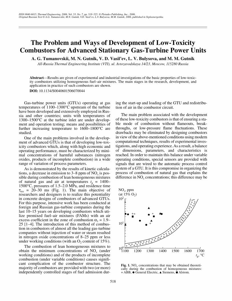
= 20–30 ms (Fig. 1). The main objective ofresearchers and designers is to realize this potentialityin concrete designs of combustors of advanced GTUs.For this purpose, intensive work has been conducted atforeign and Russian gas-turbine companies during thelast 10–15 years on developing combustors which uti-lize premixed fuel–air mixtures (FAMs) with an airexcess coefficient in the zone of combustion
α
1
= 1.9–25 [1–4]. The introduction of this method of combus-tion in combustors of almost all the leading gas-turbinecompanies without injection of water or steam resultedin nitrogen oxide concentrations of 8–25 ppm or lessunder working conditions (with an O
2
content of 15%).The combustion of lean homogeneous mixtures to
obtain the minimum concentrations of NO
x
(underworking conditions) and of the products of incompletecombustion (under variable conditions) causes signifi-cant complication of the combustor structure. Themajority of combustors are provided with two (or more)independently controlled stages of fuel admission dur-
ing the start-up and loading of the GTU and redistribu-tion of air in the combustor circuit.
The main problem associated with the developmentof these low-toxicity combustors is that of ensuring a sta-ble mode of combustion without flameouts, break-throughs, or low-pressure flame fluctuations. Thesedrawbacks may be eliminated by designing combustorsin view of the above-mentioned conditions using moderncomputational techniques, results of experimental inves-tigations, and operating experience. As a result, a balanceof dimensions, parameters, and characteristics isreached. In order to maintain this balance under variableoperating conditions, special sensors are provided withsignals that are wired to the automatic process controlsystem of a GTU. It is this compromise in organizing theprocess of combustion of natural gas that explains thedifference in NO
x
concentrations; this difference may be
The Problem and Ways of Development of Low-Toxicity Combustors for Advanced Stationary Gas-Turbine Power Units
A. G. Tumanovskii, M. N. Gutnik, V. D. Vasil’ev, L. V. Bulysova, and M. M. Gutnik
All-Russia Thermal Engineering Institute (VTI), ul. Avtozavodskaya 14/23, Moscow, 115280 Russia
Abstract
—Results are given of experimental and industrial investigations of the basic properties of low-toxic-ity combustors utilizing homogeneous fuel–air mixtures. The main stages in the research, development, andapplication in practice of such combustors are shown.
DOI:
10.1134/S0040601506070044
10
1
10
0
1100
NO
x
, ppm
t
g
, °C
10
2
1200 1300 1400 1500 1600 1700
(at 15% O
2
)
Fig. 1.
NO
x
concentrations that may be obtained theoreti-cally during the combustion of homogeneous mixtures:+ ABB,
�
General Electric,
�
Siemens,
�
Alstom.
THERMAL ENGINEERING
Vol. 53
No. 7
2006
THE PROBLEM AND WAYS OF DEVELOPMENT OF LOW-TOXICITY COMBUSTORS 519
attained and has in fact been attained by leading foreigncompanies for stationary GTUs (see Fig. 1).
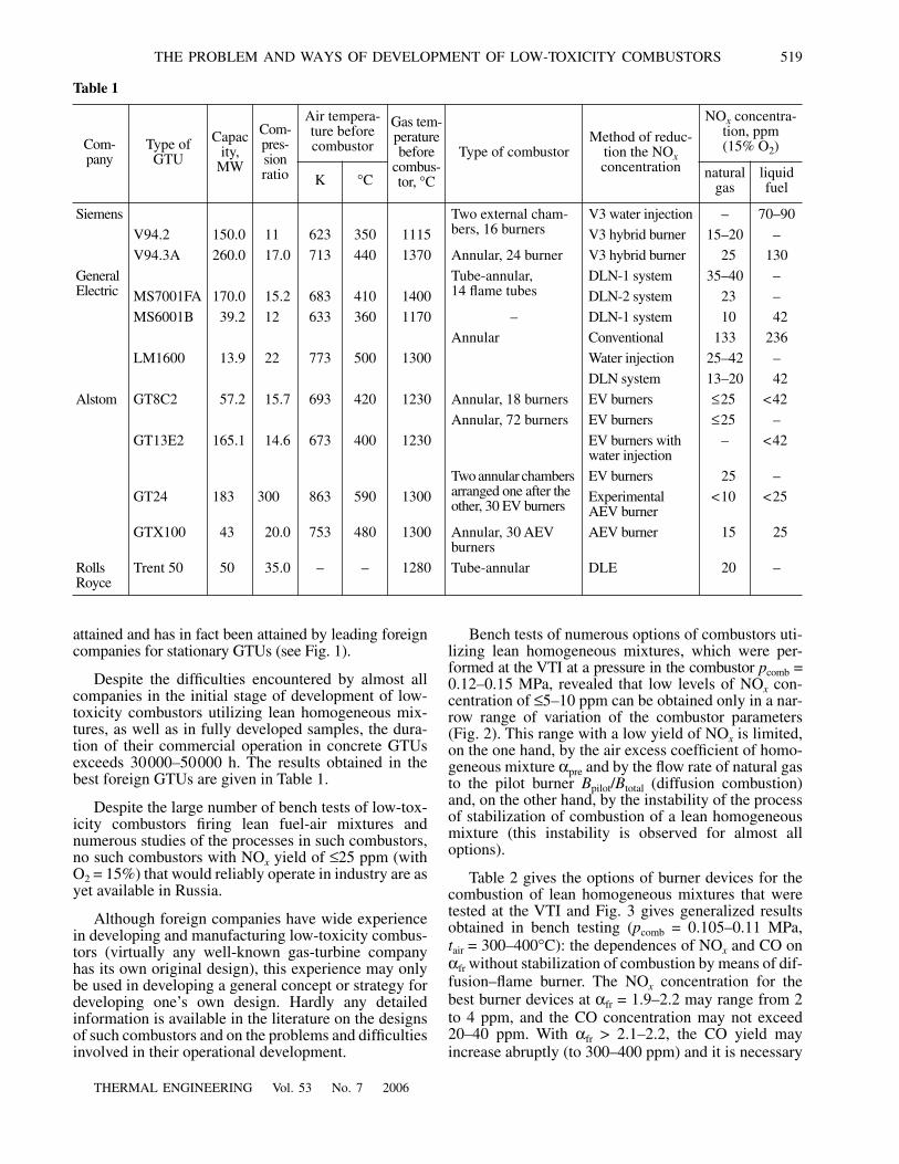
Despite the difficulties encountered by almost allcompanies in the initial stage of development of low-toxicity combustors utilizing lean homogeneous mix-tures, as well as in fully developed samples, the dura-tion of their commercial operation in concrete GTUsexceeds 30000–50000 h. The results obtained in thebest foreign GTUs are given in Table 1.
Despite the large number of bench tests of low-tox-icity combustors firing lean fuel-air mixtures andnumerous studies of the processes in such combustors,no such combustors with NO
x
yield of
≤
25 ppm (withO
2
= 15%) that would reliably operate in industry are asyet available in Russia.
Although foreign companies have wide experiencein developing and manufacturing low-toxicity combus-tors (virtually any well-known gas-turbine companyhas its own original design), this experience may onlybe used in developing a general concept or strategy fordeveloping one’s own design. Hardly any detailedinformation is available in the literature on the designsof such combustors and on the problems and difficultiesinvolved in their operational development.
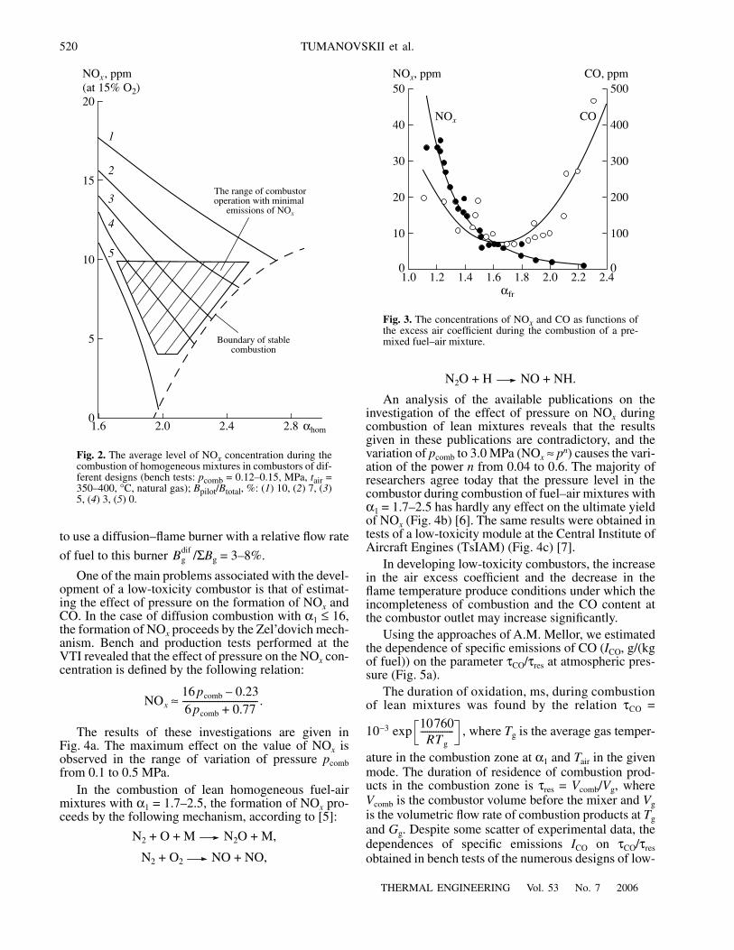
Bench tests of numerous options of combustors uti-lizing lean homogeneous mixtures, which were per-formed at the VTI at a pressure in the combustor
p
comb
=0.12–0.15 MPa, revealed that low levels of NO
x
con-centration of
≤
5–10 ppm can be obtained only in a nar-row range of variation of the combustor parameters(Fig. 2). This range with a low yield of NO
x
is limited,on the one hand, by the air excess coefficient of homo-geneous mixture
α
pre
and by the flow rate of natural gasto the pilot burner
B
pilot
/
B
total
(diffusion combustion)and, on the other hand, by the instability of the processof stabilization of combustion of a lean homogeneousmixture (this instability is observed for almost alloptions).
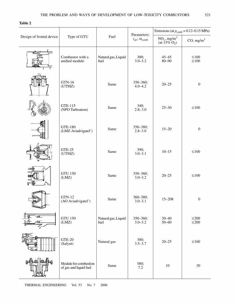
Table 2 gives the options of burner devices for thecombustion of lean homogeneous mixtures that weretested at the VTI and Fig. 3 gives generalized resultsobtained in bench testing (
p
comb
= 0.105–0.11 MPa,
t
air
= 300–400
°
C): the dependences of NO
x
and CO on
α
fr
without stabilization of combustion by means of dif-fusion–flame burner. The NO
x
concentration for thebest burner devices at
α
fr
= 1.9–2.2 may range from 2to 4 ppm, and the CO concentration may not exceed20–40 ppm. With
α
fr
> 2.1–2.2, the CO yield mayincrease abruptly (to 300–400 ppm) and it is necessary
Table 1
Com-pany
Type ofGTU
Capacity,
MW
Com-pres-sion ratio
Air tempera-ture beforecombustor
Gas tem-perature before
combus-tor,
°
C
Type of combustorMethod of reduc-
tion the NO
x
concentration
NO
x
concentra-tion, ppm(15% O
2
)
K
°
C naturalgas
liquid fuel
Siemens Two external cham-bers, 16 burners
V3 water injection – 70–90
V94.2 150.0 11 623 350 1115 V3 hybrid burner 15–20 –
V94.3A 260.0 17.0 713 440 1370 Annular, 24 burner V3 hybrid burner 25 130
GeneralElectric
Tube-annular,14 flame tubes
DLN-1 system 35–40 –
MS7001FA 170.0 15.2 683 410 1400 DLN-2 system 23 –
MS6001B 39.2 12 633 360 1170 – DLN-1 system 10 42
Annular Conventional 133 236
LM1600 13.9 22 773 500 1300 Water injection 25–42 –
DLN system 13–20 42
Alstom GT8C2 57.2 15.7 693 420 1230 Annular, 18 burners EV burners
≤
25 <42
Annular, 72 burners EV burners
≤
25 –
GT13E2 165.1 14.6 673 400 1230 EV burners with water injection
– <42
Two annular chambers arranged one after the other, 30 EV burners
EV burners 25 –
GT24 183 300 863 590 1300 Experimental AEV burner
<10 <25
GTX100 43 20.0 753 480 1300 Annular, 30 AEV burners
AEV burner 15 25
Rolls Royce
Trent 50 50 35.0 – – 1280 Tube-annular DLE 20 –
520
THERMAL ENGINEERING
Vol. 53
No. 7
2006
TUMANOVSKII et al.
5
01.6
NO
x
, ppm
1
2
3
4
5
2.0 2.4 2.8
10
15
20
α
hom
(at 15% O
2
)
The range of combustor
Boundary of stablecombustion
operation with minimal emissions of NO
x
Fig. 2.
The average level of NO
x
concentration during thecombustion of homogeneous mixtures in combustors of dif-ferent designs (bench tests:
p
comb
= 0.12–0.15, MPa,
t
air
=350–400,
°
C, natural gas);
B
pilot
/
B
total
, %: (
1
) 10, (
2
) 7, (
3
)5, (
4
) 3, (
5
) 0.
to use a diffusion–flame burner with a relative flow rate
of fuel to this burner /
Σ
B
g
= 3–8%.
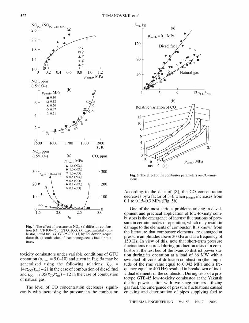
One of the main problems associated with the devel-opment of a low-toxicity combustor is that of estimat-ing the effect of pressure on the formation of NO
x
andCO. In the case of diffusion combustion with
α
1
≤
16,the formation of NO
x
proceeds by the Zel’dovich mech-anism. Bench and production tests performed at theVTI revealed that the effect of pressure on the NO
x
con-centration is defined by the following relation:
The results of these investigations are given inFig. 4a. The maximum effect on the value of NO
x
isobserved in the range of variation of pressure
p
comb
from 0.1 to 0.5 MPa.In the combustion of lean homogeneous fuel-air
mixtures with
α
1
= 1.7–2.5, the formation of NO
x
pro-ceeds by the following mechanism, according to [5]:
N
2
+ O + M N
2
O + M,
N
2
+ O
2
NO + NO,
Bgdif
NOx
16 pcomb 0.23–6 pcomb 0.77+----------------------------------.≈
N
2
O + H NO + NH.
An analysis of the available publications on theinvestigation of the effect of pressure on NO
x
duringcombustion of lean mixtures reveals that the resultsgiven in these publications are contradictory, and thevariation of
p
comb
to 3.0 MPa (NO
x
≈
p
n
) causes the vari-ation of the power
n
from 0.04 to 0.6. The majority ofresearchers agree today that the pressure level in thecombustor during combustion of fuel–air mixtures with
α
1
= 1.7–2.5 has hardly any effect on the ultimate yieldof NO
x
(Fig. 4b) [6]. The same results were obtained intests of a low-toxicity module at the Central Institute ofAircraft Engines (TsIAM) (Fig. 4c) [7].
In developing low-toxicity combustors, the increasein the air excess coefficient and the decrease in theflame temperature produce conditions under which theincompleteness of combustion and the CO content atthe combustor outlet may increase significantly.
Using the approaches of A.M. Mellor, we estimatedthe dependence of specific emissions of CO (
I
CO
, g/(kgof fuel)) on the parameter τCO/τres at atmospheric pres-sure (Fig. 5a).
The duration of oxidation, ms, during combustionof lean mixtures was found by the relation τCO =
10−3 exp , where Tg is the average gas temper-
ature in the combustion zone at α1 and Tair in the givenmode. The duration of residence of combustion prod-ucts in the combustion zone is τres = Vcomb/Vg, whereVcomb is the combustor volume before the mixer and Vgis the volumetric flow rate of combustion products at Tgand Gg. Despite some scatter of experimental data, thedependences of specific emissions ICO on τCO/τresobtained in bench tests of the numerous designs of low-
10760RTg
---------------
50
01.0
NOx, ppm
αfr
1.2 1.4 1.6 1.8 2.0 2.2 2.4
40
30
20
10
500
0
400
300
200
100
CO, ppm
NOx CO
Fig. 3. The concentrations of NOx and CO as functions ofthe excess air coefficient during the combustion of a pre-mixed fuel–air mixture.
THERMAL ENGINEERING Vol. 53 No. 7 2006
THE PROBLEM AND WAYS OF DEVELOPMENT OF LOW-TOXICITY COMBUSTORS 521
Table 2
Design of frontal device Type of GTU Fuel Parameters:tair ; αcomb
Emissions (at pcomb = 0.12–0.15 MPa)
NOx, mg/m3
(at 15% O2) CO, mg/m3
Combustor with aunified module
Natural gas, Liquid fuel
300;3.0–3.2
45–4580–90
≤100≤100
GTN-16(UTMZ) Same 350–360;
4.0–4.2 20–25 0
GTE-115(NPO Turboatom) Same 340;
2.8; 3.0 25–30 ≤100
GTE-180(LMZ-Aviadvigatel’) Same 350–380;
2.8–3.0 15–20 0
GTE-25(UTMZ) Same 390;
3.0–3.1 10–15 ≤100
GTU 150(LMZ) Same 350–360;
3.0–3.2 20–25 ≤100
GTN-12(AO Aviadvigatel’) Same 360–380;
3.0–3.1 15–208 0
GTU 150(LMZ)
Natural gas, Liquid fuel
350–360;3.0–3.2
30–4050–60
≤200≤200
GTE-20(Salyut) Natural gas 380;
3.5–3.7 20–25 ≤100
Module for combustion of gas and liquid fuel Same 580;
7.2 10 30
522
THERMAL ENGINEERING Vol. 53 No. 7 2006
TUMANOVSKII et al.
toxicity combustors under variable conditions of GTUoperation (αcomb = 5.0–10) and given in Fig. 5a may begeneralized using the following relations: ICO =14(τCO/τres) – 21 in the case of combustion of diesel fueland ICO = 7.35(τCO/τres) – 12 in the case of combustionof natural gas.
The level of CO concentration decreases signifi-cantly with increasing the pressure in the combustor.
According to the data of [8], the CO concentrationdecreases by a factor of 3–6 when pcomb increases from0.1 to 0.15–0.3 MPa (Fig. 5b).
One of the most serious problems arising in devel-opment and practical application of low-toxicity com-bustors is the emergence of intense fluctuations of pres-sure in certain modes of operation, which may result indamage to the elements of combustor. It is known fromthe literature that combustor elements are damaged atpressure amplitudes above 30 kPa and at a frequency of150 Hz. In view of this, note that short-term pressurefluctuations recorded during production tests of a com-bustor at the test bed of the Ivanovo district power sta-tion during its operation at a load of 86 MW with aswitched-off zone of diffusion combustion (the ampli-tude of the rms value equal to 0.042 MPa and a fre-quency equal to 400 Hz) resulted in breakdown of indi-vidual elements of the combustor. During tests of a pro-totype GTE-45 low-toxicity combustor at the Yakutskdistrict power station with two-stage burners utilizinggas fuel, the emergence of pressure fluctuations causedcracking and deterioration of pipes supplying fuel to
2.6
2.2
1.8
1.4
1.0
NOpair/NOpair = 0.1 MPa
12345
NOx, ppm(15% O2)
6
4
2
0
30
20
10
0
300
200
100
01.5 2.0 2.5 3.0
αfr
NOx, ppm(15% O2) CO, ppm
0 0.2 0.4 0.6 0.8 1.0 1.2pcomb, MPa
pcomb, MPa
1500 1600 1700 1800 1900
0.100.120.200.470.71
pcomb, MPa1.6 (NOx)1.0 (NOx)1.0 (CO)0.5 (NOx)0.5 (CO)0.1 (NOx)0.1 (CO)
T, K
Tair = 700–740 K
(b)
(c)
(a)
Fig. 4. The effect of pressure on NOx: (a) diffusion combus-tion ((1) GT-100–750; (2) GTK-3; (3) experimental com-bustor, liquid fuel; (4) GT-25-700; (5) by Zel’dovich’s equa-tion); (b, c) combustion of lean homogeneous fuel-air mix-tures.
120
80
40
1 5 9 13 τCO/τres
pcomb ≈ 0.1 MPa
ICO, kg
Diesel fuel
Natural gas
(a)
(b)
12
10
8
6
4
2
010
63 0.3
0.1
Relative variation of CO
mspcomb, MPa
Fig. 5. The effect of the combustor parameters on CO emis-sions.
THERMAL ENGINEERING Vol. 53 No. 7 2006
THE PROBLEM AND WAYS OF DEVELOPMENT OF LOW-TOXICITY COMBUSTORS 523
the burners, as well as of some elements of the coolingsystem of the flame tube.
In numerous recent studies, attempts have beenmade to theoretically and experimentally estimate theranges in which pressure fluctuations arise in low-tox-icity combustors and to determine the acoustic proper-ties of these combustors. However, the use of these esti-mates enables one to obtain only qualitative data on thefrequencies and amplitudes of pressure oscillations.
In the majority of studies, concrete methods ofincreasing the stability of combustion are investigated.Such methods largely involve:
(i) variation of the natural frequencies of the com-bustor and of the method of fuel delivery to this com-bustor;
(ii) variation of the ratio of fuel flow rates betweendiffusion-flame and homogeneous burners;
(iii) sequential (portion-wise) admission of a leanfuel–air mixture along the combustor circuit;
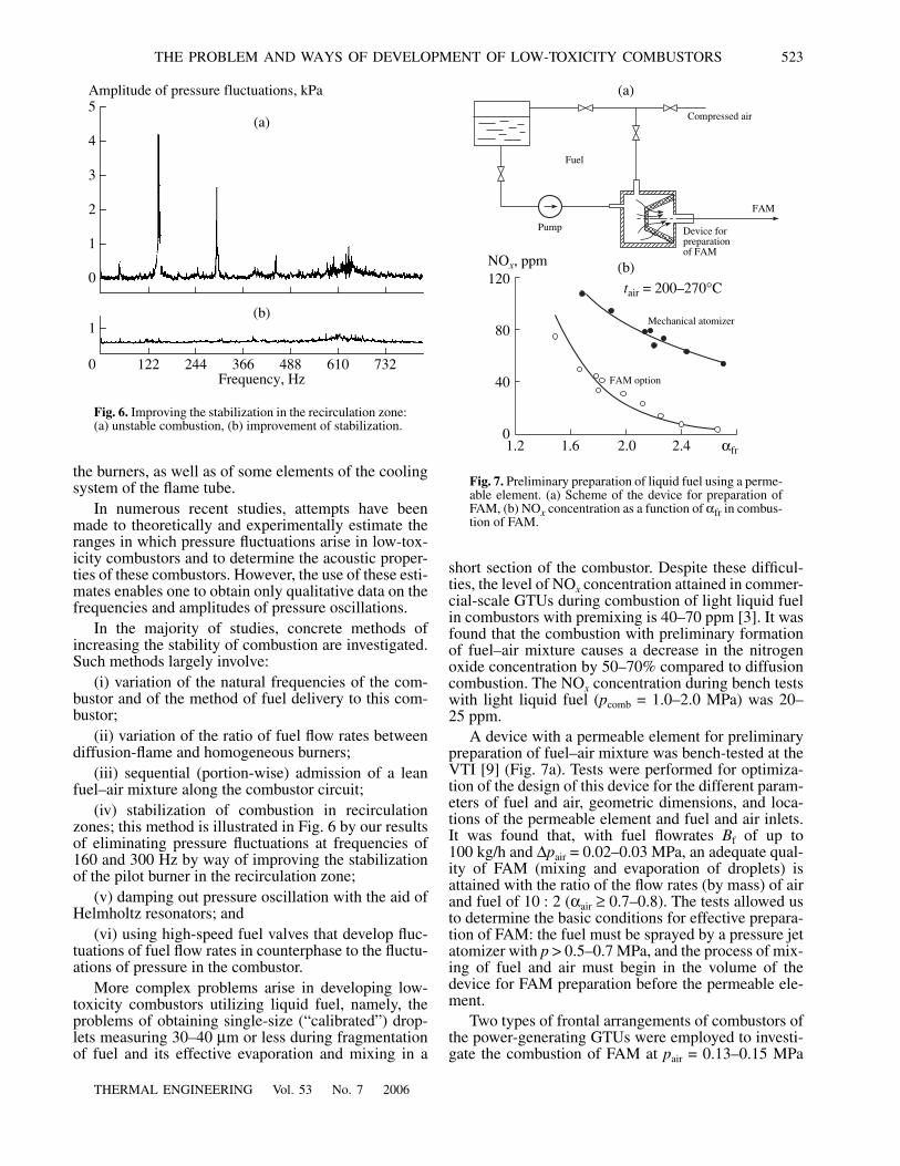
(iv) stabilization of combustion in recirculationzones; this method is illustrated in Fig. 6 by our resultsof eliminating pressure fluctuations at frequencies of160 and 300 Hz by way of improving the stabilizationof the pilot burner in the recirculation zone;
(v) damping out pressure oscillation with the aid ofHelmholtz resonators; and
(vi) using high-speed fuel valves that develop fluc-tuations of fuel flow rates in counterphase to the fluctu-ations of pressure in the combustor.
More complex problems arise in developing low-toxicity combustors utilizing liquid fuel, namely, theproblems of obtaining single-size (“calibrated”) drop-lets measuring 30–40 µm or less during fragmentationof fuel and its effective evaporation and mixing in a
short section of the combustor. Despite these difficul-ties, the level of NOx concentration attained in commer-cial-scale GTUs during combustion of light liquid fuelin combustors with premixing is 40–70 ppm [3]. It wasfound that the combustion with preliminary formationof fuel–air mixture causes a decrease in the nitrogenoxide concentration by 50–70% compared to diffusioncombustion. The NOx concentration during bench testswith light liquid fuel (pcomb = 1.0–2.0 MPa) was 20–25 ppm.
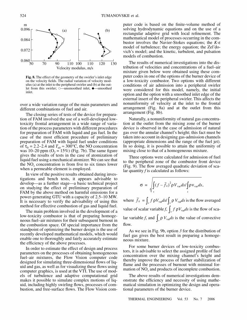
A device with a permeable element for preliminarypreparation of fuel–air mixture was bench-tested at theVTI [9] (Fig. 7a). Tests were performed for optimiza-tion of the design of this device for the different param-eters of fuel and air, geometric dimensions, and loca-tions of the permeable element and fuel and air inlets.It was found that, with fuel flowrates Bf of up to100 kg/h and ∆pair = 0.02–0.03 MPa, an adequate qual-ity of FAM (mixing and evaporation of droplets) isattained with the ratio of the flow rates (by mass) of airand fuel of 10 : 2 (αair ≥ 0.7–0.8). The tests allowed usto determine the basic conditions for effective prepara-tion of FAM: the fuel must be sprayed by a pressure jetatomizer with p > 0.5–0.7 MPa, and the process of mix-ing of fuel and air must begin in the volume of thedevice for FAM preparation before the permeable ele-ment.
Two types of frontal arrangements of combustors ofthe power-generating GTUs were employed to investi-gate the combustion of FAM at pair = 0.13–0.15 MPa
1
0 122Frequency, Hz
244 366 488 610 732
(b)
5(a)
Amplitude of pressure fluctuations, kPa
4
3
2
1
0
Fig. 6. Improving the stabilization in the recirculation zone:(a) unstable combustion, (b) improvement of stabilization.
NOx, ppm120
80
40
01.2 1.6 2.0 2.4
Mechanical atomizer
tair = 200–270°C
αfr
FAM option
(b)
(a)
Fuel
Pump Device for
FAM
Compressed air
preparationof FAM
Fig. 7. Preliminary preparation of liquid fuel using a perme-able element. (a) Scheme of the device for preparation ofFAM, (b) NOx concentration as a function of αfr in combus-tion of FAM.
524
THERMAL ENGINEERING Vol. 53 No. 7 2006
TUMANOVSKII et al.
over a wide variation range of the main parameters anddifferent combinations of fuel and air.
The closing series of tests of the device for prepara-tion of FAM involved the use of a well-developed low-toxicity frontal arrangement in a wide range of varia-tion of the process parameters with different proceduresfor preparation of FAM with liquid and gas fuel. In thecase of the most efficient procedure of preliminarypreparation of FAM with liquid fuel under conditionsof τfr = 2.2–2.4 and Tair ≈ 300°C, the NO concentrationwas 10–20 ppm (O2 = 15%) (Fig. 7b). The same figuregives the results of tests in the case of atomization ofliquid fuel using a mechanical atomizer. We can see thatthe NOx concentration is from five to six times lowerwhen a permeable element is employed.
In view of the positive results obtained during inves-tigations and bench tests, it appears advisable todevelop—as a further stage—a basic technical projecton studying the effect of preliminary preparation ofFAM by the above method on harmful emissions for apower-generating GTU with a capacity of 2.5–10 MW.It is necessary to verify the advisability of using thismethod for effective combustion of gas and liquid fuel.
The main problem involved in the development of alow-toxicity combustor is that of preparing homoge-neous fuel–air mixtures for their subsequent burnout inthe combustion space. Of special importance from thestandpoint of optimizing the burner design is the use ofrecently developed mathematical models, which wouldenable one to thoroughly and fairly accurately estimatethe efficiency of the above processes.
In order to estimate the effect of design and processparameters on the processes of obtaining homogeneousfuel–air mixtures, the Flow Vision computer codedesigned for simulating three-dimensional flows of liq-uid and gas, as well as for visualizing these flows usingcomputer graphics, is used at the VTI. The use of mod-els of turbulence and adaptive computational gridmakes it possible to simulate complex motions of liq-uid, including highly swirling flows, processes of com-bustion, and free-surface flows. The Flow Vision com-
puter code is based on the finite-volume method ofsolving hydrodynamic equations and on the use of arectangular adaptive grid with local refinement. Themathematical model of processes occurring in the com-bustor involves the Navier-Stokes equations; the K-εmodel of turbulence; the energy equation; the Zel’do-vich’s model; and the kinetic, turbulent, and pulsationmodels of combustion.
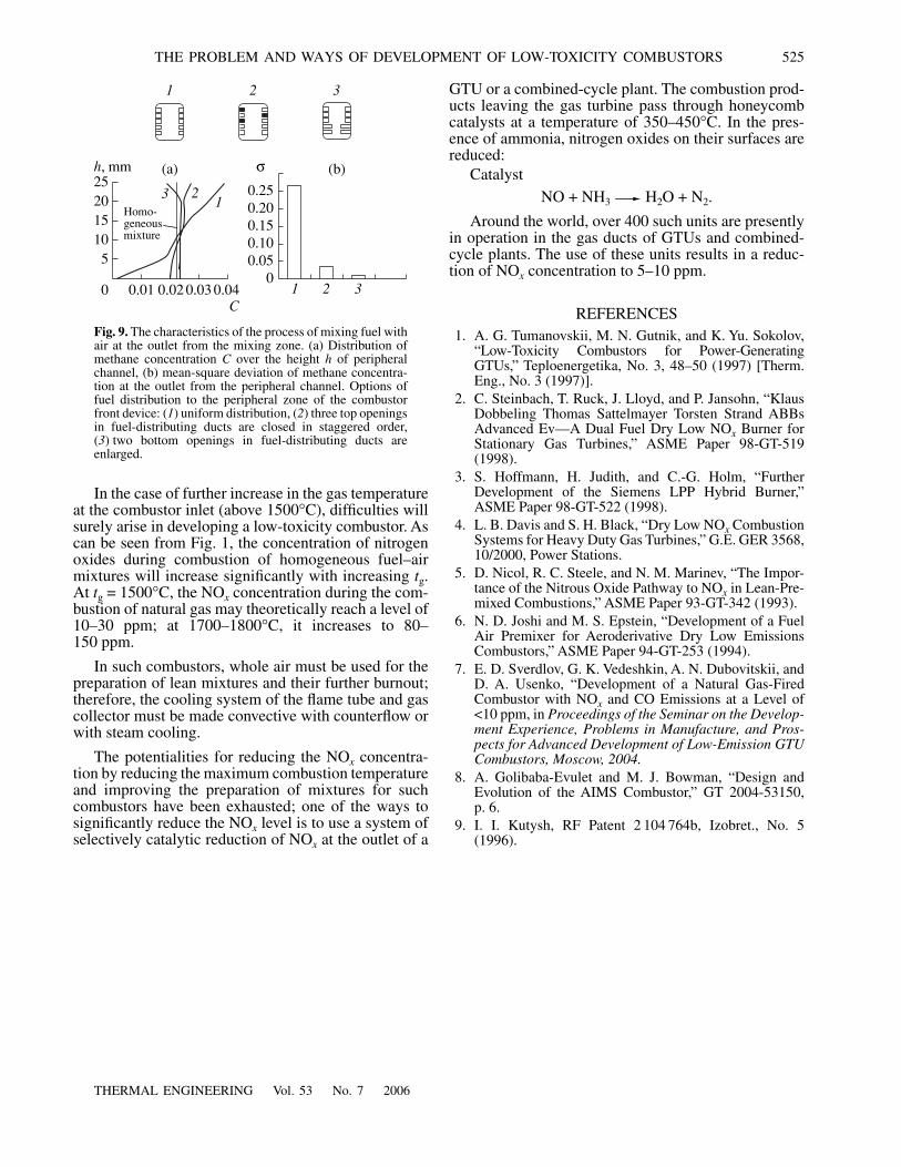
The results of numerical investigations into the dis-tribution of velocities and concentrations of a fuel–airmixture given below were obtained using these com-puter codes in one of the options of the burner device ofa low-toxicity combustor. Two options with differentconditions of air admission into a peripheral swirlerwere considered for this model, namely, the initialoption and the option with a smoothed inlet edge of theexternal insert of the peripheral swirler. This affects thenonuniformity of velocity at the inlet to the frontalarrangement (Fig. 8a) and at the outlet from thisarrangement (Fig. 8b).
Naturally, a nonuniformity of natural gas concentra-tion at the outlet from the mixing zone of the burnerdevice is observed in the case of admission of naturalgas over the annular channel’s height; this fact must betaken into account in designing gas-admission channels(appropriate dimensions and the range of the fuel jet).In so doing, it is possible to attain the uniformity ofmixing close to that of a homogeneous mixture.
Three options were calculated for admission of fuelto the peripheral zone of the combustor front device(Fig. 9). The flow averaged quadratic deviation of sca-lar quantity f is calculated as follows:
where = ρVvards/ Vvards is the flow averaged
value of scalar variable f, ρVvards is the flow of sca-
lar variable f, and Vvards is the value of convective
flow.
As we see in Fig. 9b, option 3 for the distribution offuel gas gives the best result in preparing a homoge-neous mixture.
For some burner devices of low-toxicity combus-tors, it is advisable to select the assigned profile of fuelconcentration over the mixing channel’s height andthereby improve the process of further stabilization offlame and the processes of burnout with minimal for-mation of NOx and products of incomplete combustion.
The above results of numerical investigations dem-onstrate the efficiency and necessity of using mathe-matical simulation in optimizing the design and opera-tional parameters of the burner device.
σ f f k–( )2ρVvar s/ ρνvar sd
s
∫d
s
∫ ,=
f k fs∫ ρ
s∫f
s∫ρ
s∫
0.096
0.06050
m
Velocity modulus, m/s
0.084
0.072
70 90 110 100
(a)
110 120 130
(b)
Fig. 8. The effect of the geometry of the swirler’s inlet edgeon the velocity fields. The radial variation of velocity mod-ulus (a) at the inlet to the peripheral swirler and (b) at the out-let from this swirler; �—unsmoothed inlet, �—smoothedinlet.
THERMAL ENGINEERING Vol. 53 No. 7 2006
THE PROBLEM AND WAYS OF DEVELOPMENT OF LOW-TOXICITY COMBUSTORS 525
In the case of further increase in the gas temperatureat the combustor inlet (above 1500°C), difficulties willsurely arise in developing a low-toxicity combustor. Ascan be seen from Fig. 1, the concentration of nitrogenoxides during combustion of homogeneous fuel–airmixtures will increase significantly with increasing tg.At tg = 1500°C, the NOx concentration during the com-bustion of natural gas may theoretically reach a level of10–30 ppm; at 1700–1800°C, it increases to 80–150 ppm.
In such combustors, whole air must be used for thepreparation of lean mixtures and their further burnout;therefore, the cooling system of the flame tube and gascollector must be made convective with counterflow orwith steam cooling.
The potentialities for reducing the NOx concentra-tion by reducing the maximum combustion temperatureand improving the preparation of mixtures for suchcombustors have been exhausted; one of the ways tosignificantly reduce the NOx level is to use a system ofselectively catalytic reduction of NOx at the outlet of a
GTU or a combined-cycle plant. The combustion prod-ucts leaving the gas turbine pass through honeycombcatalysts at a temperature of 350–450°C. In the pres-ence of ammonia, nitrogen oxides on their surfaces arereduced:
CatalystNO + NH3 H2O + N2.
Around the world, over 400 such units are presentlyin operation in the gas ducts of GTUs and combined-cycle plants. The use of these units results in a reduc-tion of NOx concentration to 5–10 ppm.
REFERENCES1. A. G. Tumanovskii, M. N. Gutnik, and K. Yu. Sokolov,
“Low-Toxicity Combustors for Power-GeneratingGTUs,” Teploenergetika, No. 3, 48–50 (1997) [Therm.Eng., No. 3 (1997)].
2. C. Steinbach, T. Ruck, J. Lloyd, and P. Jansohn, “KlausDobbeling Thomas Sattelmayer Torsten Strand ABBsAdvanced Ev—A Dual Fuel Dry Low NOx Burner forStationary Gas Turbines,” ASME Paper 98-GT-519(1998).
3. S. Hoffmann, H. Judith, and C.-G. Holm, “FurtherDevelopment of the Siemens LPP Hybrid Burner,”ASME Paper 98-GT-522 (1998).
4. L. B. Davis and S. H. Black, “Dry Low NOx CombustionSystems for Heavy Duty Gas Turbines,” G.E. GER 3568,10/2000, Power Stations.
5. D. Nicol, R. C. Steele, and N. M. Marinev, “The Impor-tance of the Nitrous Oxide Pathway to NOx in Lean-Pre-mixed Combustions,” ASME Paper 93-GT-342 (1993).
6. N. D. Joshi and M. S. Epstein, “Development of a FuelAir Premixer for Aeroderivative Dry Low EmissionsCombustors,” ASME Paper 94-GT-253 (1994).
7. E. D. Sverdlov, G. K. Vedeshkin, A. N. Dubovitskii, andD. A. Usenko, “Development of a Natural Gas-FiredCombustor with NOx and CO Emissions at a Level of<10 ppm, in Proceedings of the Seminar on the Develop-ment Experience, Problems in Manufacture, and Pros-pects for Advanced Development of Low-Emission GTUCombustors, Moscow, 2004.
8. A. Golibaba-Evulet and M. J. Bowman, “Design andEvolution of the AIMS Combustor,” GT 2004-53150,p. 6.
9. I. I. Kutysh, RF Patent 2 104 764b, Izobret., No. 5(1996).
h, mm252015105
0 0.01 0.02 0.03 0.04C
(a)
123
Homo-
1 2 3
(b)σ0.250.200.150.100.05
0
1 2 3
mixturegeneous
Fig. 9. The characteristics of the process of mixing fuel withair at the outlet from the mixing zone. (a) Distribution ofmethane concentration C over the height h of peripheralchannel, (b) mean-square deviation of methane concentra-tion at the outlet from the peripheral channel. Options offuel distribution to the peripheral zone of the combustorfront device: (1) uniform distribution, (2) three top openingsin fuel-distributing ducts are closed in staggered order,(3) two bottom openings in fuel-distributing ducts areenlarged.