Embed Size (px)
Citation preview
The Practical Design Approach to Coatings and Liners for the Rehabilitation of Cylindrically-Shaped Manhole Structures
EXECUTIVE SUMMARY
The lack to date of an industry produced design standard for coatings and linings used in the renewal of sanitary sewer manholes by the manufacturers/suppliers of these technologies has created a desire within the engineering community to find a methodology, or methodologies, which can develop this needed engineering skillset. This paper presents a pragmatic discussion regarding uses for coatings and linings with respect to buried structures and gets back to the basics by defining them with respect to their in place performance.
Further, this paper presents a soil-structure interaction discussion on the likely lateral loading regime for a cylindrically-shaped vertical shaft based on the significant amount of experimental and empirical (field) research that has been accumulated on them by the geotechnical engineering community. What this en-gineering specialist segment has found is that for the case of the cylindrically-shaped vertical shaft struc-ture the true lateral earth pressure does not increase linearly with depth as the Rankine theory would suggest; but, rather, the lateral earth pressure increases up to a point with depth and then appears to increase very little, if at all, for the subsequent depth of the installation. This point is reached approxi-mately when the value of h/r (depth/radius of structure) reaches eight. This drastic reduction of up to 80% from the Rankine theory's lateral loading value is thought to be brought as the result of a very small amount of subsidence in the backfill surrounding the cylindrical structure and the very beneficial results of the three-dimensional arching that subsequently takes place. This leaves the engineer to address the dominant design loading coming from any external hydrostatic pressure coming from any groundwater present around the cylindrical structure which does increase linearly with depth below the elevation of the phreatic surface (or water table).
The paper then presents a practical approach to designing the wall thickness of coatings and liners based upon the site specific environment of the subject manhole structure and the in situ performance require-ments of the manhole renewal technique for resetting the service life cycle. As a subset of the design approach effort, the paper reviews and subsequently dismisses the premise by at least one manufacturer that the equation X1.1 of the ASTM F1216 design appendix A is an appropriate solution for determining the required thickness for coatings and linings installed in vertically oriented cylindrical shafts.
By the corrosion protection industry's definition (NACE) of coatings and liners; a coating is a material that is applied up to 0.125 inches in thickness that develops an adhesive bond with surface of the material to be protected. When a material has been applied to a thickness of more than 0.125 inches it is designated to be a liner; whether it is in a bonded or an un-bonded condition.
Selection of a cementitious mortar liner material is first based upon the pH of the wall surface and whether the routine operating condition of the manhole will be one of immersion service. In a CML only applica-tion, a minimum wall thickness of 0.50-inches can be used for shallow manholes (0-5 feet in depth) and a minimum wall thickness of 0.75-inches should be used for intermediate depth manholes (greater than 5
Page 1 of 18
feet but less than 15 feet in depth); and deeper manholes should receive a minimum wall thickness of 1.00-inches. The measurement basis of this thickness is from the peaks of the roughened surface to the finished level of the mortar surface.
Selection of a polymeric coating material historically is based upon the material(s) used in the construction of the manhole and its surface profile. A minimum wall thickness of 0.100-inches is recommended for new construction applications; and a minimum thickness of 0.125-inches for renewal of existing structures.
Un-bonded shell-type liners such as cured-in-place thermosetting resin systems using a prefabricated tube material for its placement and spray-on lining systems such as polyurethanes and polyureas can be used when the dampness of the wall surface can be brought into compliance with the manufacturers' stated requirements. The minimum wall thickness required for this type of liner is based upon the site specific varying geometry of the manhole's cylindrical shape (i.e. local variations in radii), the profile of the hydro-static loading (it's increasing with depth), and the stiffness of the liner material (relating to its stability and whether failure is by flexural wall buckling or by wall shear). Given the large number of commercially available materials and their varying stiffness properties it is incumbent on the manufacturer of these systems to publish a design guide based upon the wall thickness solution fitting their specific material formulations, the end conditions created by their recommended installation practice, and the type of fail-ure mode that is expected to occur with them. For vertically oriented cylindrical shells, the design case number 6 in the referenced table 13.2 of Roark's Formulas for Stress and Strain provides a good basis for design for liners whose failure occurs in flexural buckling; however, in its current form this solution needs further refinement to reflect the true buckling resistance considering the casing effect of the existing wall structure.
The engineer in specifying a coating or a liner for the renewal of a cylindrical manhole structure using either a cementitious mortar system or an epoxy resin system need only specify the wall thickness re-quired using the above stated parameters. No site specific wall thickness design is warranted. However, when choosing to use a polymeric lining system where the cylindrical shell is likely to be un-bonded with the host manhole structure; a site specific wall thickness design is required in order to ensure that the stability of the cylinder's geometry is assured for the design life of the stated improvement to the manhole structure.
INTRODUCTION
The practical engineering design approach to finding the necessary wall thickness of a coating or a liner installed for the renewal of an existing circular manhole structure must be, by necessity, tied closely to the interactive performance properties of the coating or liner system with the manhole and the load(s) deemed likely to be acting on this structure.
While no true structural failing of these systems have been reported to date (only installation failures) as evidenced by this author's review of the literature, this paper has been prepared to address the engineer-ing community's concerns and/or confusion that has occurred due to at least one of the lining system manufacturer's recommendation being to use a wall thickness design theory borrowed from the pipe lin-ing industry (the non-mandatory Design Appendix A of the ASTM Standard F 1216) without, in this author's
Page 2 of 18
opinion, a properly done engineering consideration of the underlying technical basis for using said equa-tion(s) and their obvious lack of applicability to the wall thickness analysis of a liner installed in an existing cylindrically-shaped vertical shaft.
DEFINING THE DIFFERENCES BETWEEN COATINGS AND LINERS
When one peruses the various manufacturers' literature they will find the terms coating and lining being used almost interchangeably as it pertains to pipes and other buried structures even though these are really two different methodologies. This clouding of the definitions for coatings and liners has resulted from how these terms are used by the different segments of the engineering community's technical liter-ature base. Setting these definitions back to what they should be is paramount to developing a sound engineering approach to each of these rehabilitation techniques; as one design approach will not neces-sarily work for both of these categories due to their in place performance differences. Recognizing the differences in these two rehabilitation methods and defining the design loading scenarios pertinent to each allows the engineering community to deliver cost-effective solutions for the renewal of these im-portant infrastructure components. Presented below are this author's recommended definitions of these two renewal categories.
Coating – A coating is a liquid, liquefiable solid, or mastic composition that, after application to a surface, is converted into a solid protective, decorative, or functional adherent film. In the case of being applied to the interior and/or exterior wall surface of a buried structure it is a relatively thin membrane that is dominated by in plane forces only (i.e. tensile or compressive), if any.
Liner – A liner is a sleeve or shell structure inside of the main structural component. It can be either bonded or un-bonded with the host structure's wall surface. Because of its thickness it is subject to both out-of-plane (bending) and in-plane (tensile) reactions. In the un-bonded case it must be designed to with-stand the load(s) that can or likely will come onto it from the environmental conditions acting on the host structure.
Membrane forces can develop in a coating as a consequence of deflection in the host structural element and can significantly influence the response of the host structure to load. Membrane forces have a stress stiffening effect; if tensile they effectively increase the flexural rigidity, and when compressive they de-crease it.
Shells and shell theory tell us that:
• The geometry of a shell is defined by its thickness and its mid-surface, which is a curved surface in space.
• Load is carried in the shell by a combination of membrane action and bending action • A thin shell can be very strong if membrane action dominates, in the same way that a wire can
carry a great load in tension but only a small load in bending. • No shell is completely free of bending stresses. They appear at or near point loads, line loads,
reinforcements, junctures, change of curvature and supports.
Page 3 of 18
• Any concentration of load or geometrical discontinuity can be expected to produce bending stresses which often are much larger than membrane stresses, but quite localized.
When bond strength with the existing structure's wall surface is a stated performance parameter for the coating or liner, it must be addressed in the technical design information of the product in order for the engineer to properly consider its role in the design of the required film or wall thickness. Bond strengths are typically stated in terms of the adhesive material having good lap-shear strength or good peel strength or both. Both of these bond strengths are derived by the manufacturer's formulation of the proposed polymeric material and subsequent qualification based testing.
MANHOLE REHABILITATION MATERIALS, TECHNIQUES OF THEIR INSTALLATION, AND PERFORMANCE
The design of the renewal of an existing manhole structure is evaluated for achieving the following; water-tightness (I/I elimination and preservation of the soil envelope), corrosion protection (isolation of the manhole wall from further deterioration due to the harsh environmental conditions present), and any required restoration of the wall surface (sometimes referred to as re-profiling of the wall surface). The rehabilitation methods commercially available to the design engineer at present to address these perfor-mance requirements are:
• Polymeric Coatings o Epoxy resins o Fiber-reinforced epoxy resins o Polyurethane resins o Polyurea resins
• Engineered Cementitious Liners o Portland cement mortars o Microsilica mortars o Calcium aluminate mortars
• Composite Liner/Coating Systems (i.e. epoxy resin coating over cementitious liner) • Shell Liner Systems (non-bonded sleeve type liner; such as CIPP, Polyurea, and Polyurethane)
o Cured-in-Place thermoset resin liners o Polyurethane resins o Hybrid polyurea resins o Polyurea resins
Epoxy Coatings --
Epoxy coatings have long been employed by engineers to protect buried tanks, access structures, and piping systems from potential negative reactions to the fluids being stored or transported within them and/or to provide an impermeable membrane to the exterior surface of these structures to protect them against corrosion. In manhole renewal, the epoxy coating is generally employed as a protective membrane to arrest further deterioration of the existing structure while also serving as a water-tight barrier to groundwater intrusion. Because the structure is already buried in the ground, the coating must be suffi-ciently adhered to the interior wall surface to perform these two renewal functions.
Page 4 of 18
Epoxy coating materials for manhole renewal work are cured by either an amine curing agent or a poly-amide curing agent. The amine epoxies produce a hard, tightly bonded, chemical resistant (alkali, acid, and solvent) barrier, but some formulations can be somewhat sensitive to moisture and temperature dur-ing their application. Polyamide epoxies produce a superior resistance to water and salt solutions, but they do not produce the chemical resistance of the amine epoxies. Both of these epoxy types cure by chemical reaction.
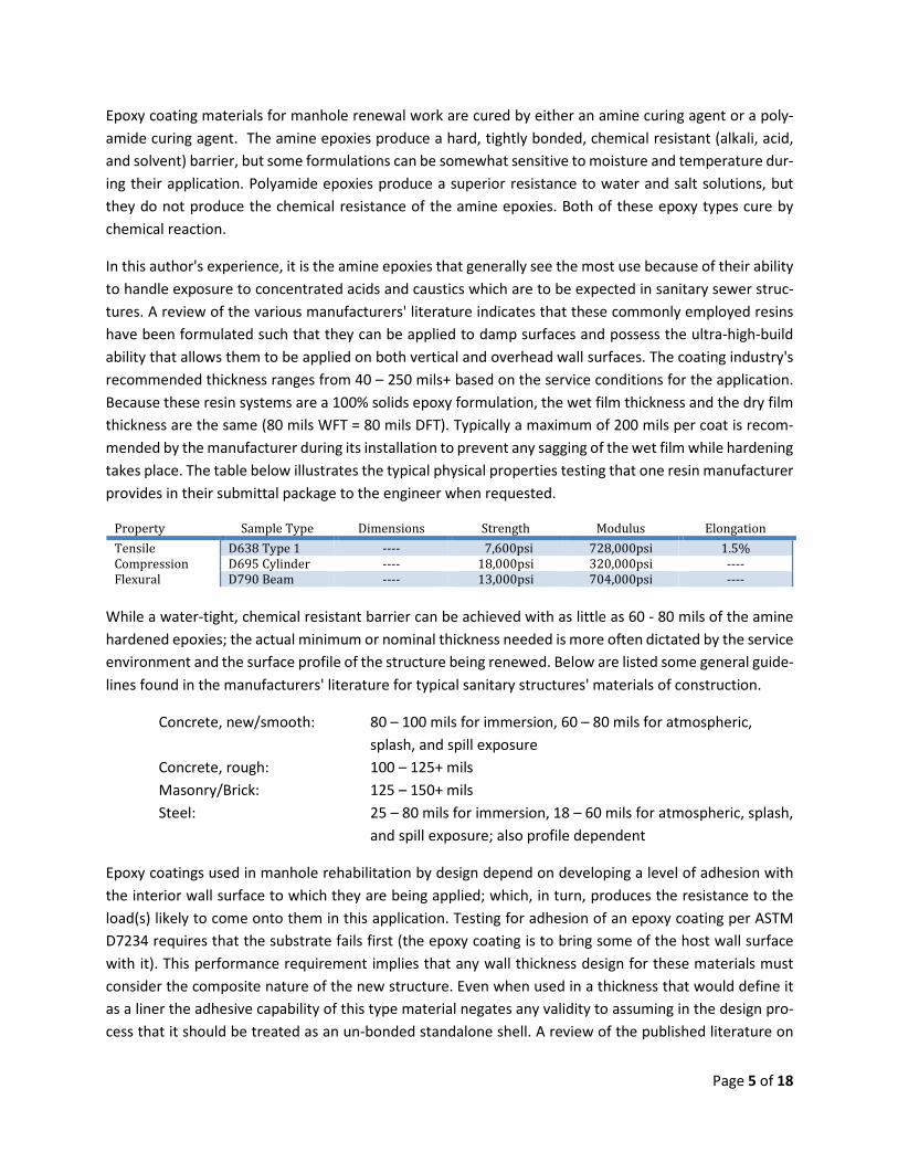
In this author's experience, it is the amine epoxies that generally see the most use because of their ability to handle exposure to concentrated acids and caustics which are to be expected in sanitary sewer struc-tures. A review of the various manufacturers' literature indicates that these commonly employed resins have been formulated such that they can be applied to damp surfaces and possess the ultra-high-build ability that allows them to be applied on both vertical and overhead wall surfaces. The coating industry's recommended thickness ranges from 40 – 250 mils+ based on the service conditions for the application. Because these resin systems are a 100% solids epoxy formulation, the wet film thickness and the dry film thickness are the same (80 mils WFT = 80 mils DFT). Typically a maximum of 200 mils per coat is recom-mended by the manufacturer during its installation to prevent any sagging of the wet film while hardening takes place. The table below illustrates the typical physical properties testing that one resin manufacturer provides in their submittal package to the engineer when requested.
Property Sample Type Dimensions Strength Modulus Elongation Tensile D638 Type 1 ---- 7,600psi 728,000psi 1.5% Compression D695 Cylinder ---- 18,000psi 320,000psi ---- Flexural D790 Beam ---- 13,000psi 704,000psi ----
While a water-tight, chemical resistant barrier can be achieved with as little as 60 - 80 mils of the amine hardened epoxies; the actual minimum or nominal thickness needed is more often dictated by the service environment and the surface profile of the structure being renewed. Below are listed some general guide-lines found in the manufacturers' literature for typical sanitary structures' materials of construction.
Concrete, new/smooth: 80 – 100 mils for immersion, 60 – 80 mils for atmospheric, splash, and spill exposure
Concrete, rough: 100 – 125+ mils Masonry/Brick: 125 – 150+ mils Steel: 25 – 80 mils for immersion, 18 – 60 mils for atmospheric, splash,
and spill exposure; also profile dependent
Epoxy coatings used in manhole rehabilitation by design depend on developing a level of adhesion with the interior wall surface to which they are being applied; which, in turn, produces the resistance to the load(s) likely to come onto them in this application. Testing for adhesion of an epoxy coating per ASTM D7234 requires that the substrate fails first (the epoxy coating is to bring some of the host wall surface with it). This performance requirement implies that any wall thickness design for these materials must consider the composite nature of the new structure. Even when used in a thickness that would define it as a liner the adhesive capability of this type material negates any validity to assuming in the design pro-cess that it should be treated as an un-bonded standalone shell. A review of the published literature on
Page 5 of 18
epoxy adhesion performance in actual sanitary sewer service environments has found that this adhesive strength typically achieves or exceeds a value of 500 psi. In contrast, laboratory testing yielded adhesive strengths approaching 2000 psi. Therefore, a practical design approach would be to assume in the design process that the adhesive strength of the coating should be 500 psi. This is equivalent to an in place per-formance against an external hydrostatic pressure head of 1154 feet.
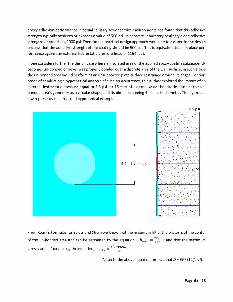
If one considers further the design case where an isolated area of the applied epoxy coating subsequently becomes un-bonded or never was properly bonded over a discrete area of the wall surface; in such a case the un-bonded area would perform as an unsupported plate surface restrained around its edges. For pur-poses of conducting a hypothetical analysis of such an occurrence, this author explored the impact of an external hydrostatic pressure equal to 6.5 psi (or 15 feet of external water head). He also set the un-bonded area's geometry as a circular shape, and its dimension being 4-inches in diameter. The figure be-low represents the proposed hypothetical example.
From Roark's Formulas for Stress and Strain we know that the maximum lift of the blister is at the center
of the un-bonded area and can be estimated by the equation ℎ𝑚𝑚𝑚𝑚𝑚𝑚 = 𝑝𝑝𝑟𝑟04
64𝐷𝐷 ; and that the maximum
stress can be found using the equation; 𝜎𝜎𝑚𝑚𝑚𝑚𝑚𝑚 = 3(1+𝑣𝑣)𝑝𝑝𝑟𝑟02
8ℎ2.
Note: In the above equation for hmax that D = Et3/ (12(1-ν2).
6.5 psi
Page 6 of 18
A 0.125 inch thick epoxy coating (the minimum industry recommended thickness for this application) after 50-years or more of continuous exposure to an external hydrostatic pressure of 6.5psi would exhibit, at the most, a maximum blister height of 0.04 inches (or 1.0 mm); and a maximum tensile stress of approxi-mately 811 psi. The tensile strain in the "blister" for this level of stress calculates to be 0.02%; versus the 1.5% strain that is this particular resin's failure in tension. Investigating the design philosophy that thicker is better, 0.250 inches of that same epoxy at the same level of external pressure and size of defect has a maximum blister height of less than 0.006-inches; or eight times smaller.
Given the performance combination of the adhesion, the tensile, and the flexural strength inherent in the epoxy resin systems engineered for service in the subject manhole rehabilitation application, it is reason-able to conclude that the coating industry's minimum recommended film thickness of 0.125 inches (125 mils) is more than a sufficient coating thickness to produce an environmental barrier for the existing wall structure and have the needed structural capability to adequately resist any external hydrostatic head; and that any greater thickness would technically be based solely upon one's desired level of cosmetic repair to the manhole wall surface (re-profiling).
Engineered Cementitious Linings --
Cementitious Lining of manholes is a cost-effective readily available solution often employed to structur-ally reinforce the existing wall section and make the structure water-tight. This current generation of en-gineered cementitious materials can come in a variety of formulations; the three dominant commercially available forms being the Type I Portland cement based mixes, Type II Portland cement based mixes, and the calcium aluminate cement based mixes. These are specially formulated fiber reinforced cement based mortar systems engineered for underground sewer structure applications. The pH of the environment along with the corrosion chemistry that is creating that pH is used to select the appropriate base cement for the renewal of the structure. The cementitious lining process uses either a hand-held low pressure sprayer followed by trowelling or a centrifugal casting tool to place the mortar onto the wall surface.
John Pitt (Iowa State University) presented a paper at the 1995 No-Dig in Toronto on Centrifugal Cast Mortar for In Situ Manhole Rehabilitation that analyzed the performance of a commercially available en-gineered cementitious liner material in a manhole structure. His National Science Foundation supported project consisted of developing a listing of the mortar's properties, structural testing of the system, and development of a wall thickness design recommendation for the subject system. The subject system was a centrifugally applied Type I Portland cement based cementitious mortar mix that produced a relatively dense liner when compared to the older technique of pneumatically casting the liner material (i.e. shot-crete or gunnite). Field constructability of the mortar mix and its application method were demonstrated using more than 900 lined manholes to validate the conclusions reached in the project's report. High-lighted in the report was the renewal of a circular brick sanitary sewer manhole in Ottawa, Illinois. This structure was eighteen (18) feet deep and forty-eight (48) inches in diameter below the cone section. Typical of many potential rehabilitation projects, the brick was fairly sound, but the mortar in the joints was soft or missing. Some signs of lost ground or soil piping around the manhole was also observed; along with groundwater inflow. A 0.75 inch thick coating of mortar was applied to this and ten (10) other similar structures in the area. The results of three years of observing these eleven (11) structures were that the
Page 7 of 18
applied thickness of the mortar was indeed adequate in resolving the previously found in situ performance defects of these brick structures.
The structural performance testing of the cementitious mortar lining included both non-axisymmetric, moment inducing horizontal loads such as was thought could occur as a result of vehicular traffic passing near the structure; and axisymmetric loading using hydraulic pressure to determine the ultimate capacity in ring compression (or elastic instability). The axisymmetric test was performed to simulate horizontal loads resulting from groundwater or from lateral soil pressures with the liner in a completely un-bonded to the host structure condition. In this axisymmetric testing, three one inch thick rings were loaded exter-nally to a maximum pressure of 80 psi at which point the seals in the test setup failed. Without any of the three rings failing at this point, this demonstrated that the one inch thick cementitious ring was capable of more than 185 feet of external hydrostatic head; at least in the short-term.
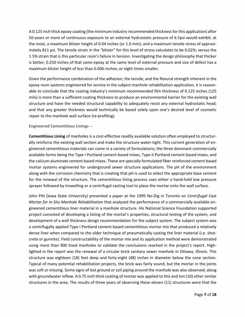
In the report, Pitt stated that the shell thickness required to resist a moment inducing load can be de-creased rapidly to a depth of two feet below the pavement. This conclusion was based upon his assump-tion of the manhole acting as an unbraced structure, and neglected the likelihood that the cover and frame might in fact offer additional resistance to the lateral stress induced by vehicular traffic. Shown below is the figure from Pitt's report graphically representing the horizontal load versus depth with con-sideration given for the impact of any improvements present on the surface (i.e. type of pavement). The plots for ratios of E/Esoil of 100, 50, 10, and 1 are for concrete pavement, asphalt pavement, gravel surface, and no paving, respectively.
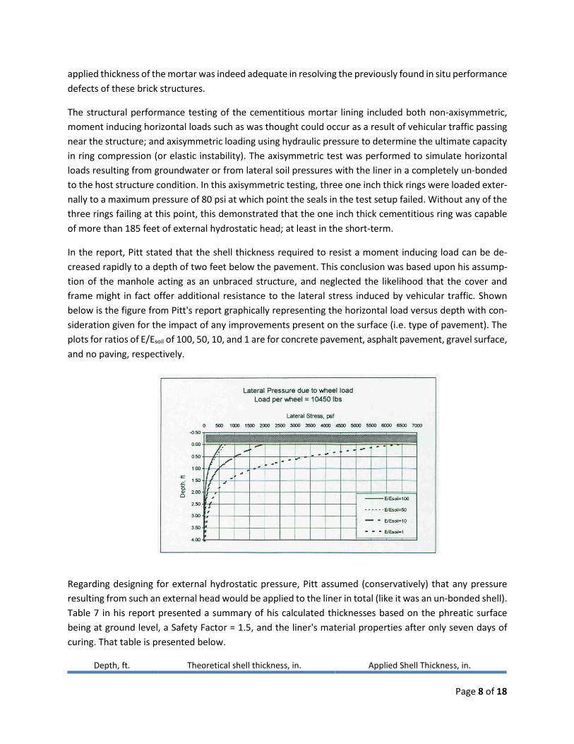
Regarding designing for external hydrostatic pressure, Pitt assumed (conservatively) that any pressure resulting from such an external head would be applied to the liner in total (like it was an un-bonded shell). Table 7 in his report presented a summary of his calculated thicknesses based on the phreatic surface being at ground level, a Safety Factor = 1.5, and the liner's material properties after only seven days of curing. That table is presented below.
Depth, ft. Theoretical shell thickness, in. Applied Shell Thickness, in.
Page 8 of 18
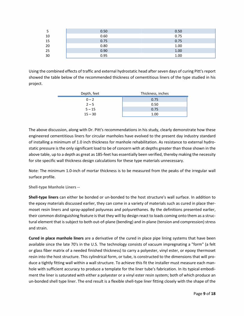
5 0.50 0.50 10 0.60 0.75 15 0.75 0.75 20 0.80 1.00 25 0.90 1.00 30 0.95 1.00
Using the combined effects of traffic and external hydrostatic head after seven days of curing Pitt's report showed the table below of the recommended thickness of cementitious liners of the type studied in his project.
Depth, feet Thickness, inches 0 – 2 0.75 2 – 5 0.50
5 – 15 0.75 15 – 30 1.00
The above discussion, along with Dr. Pitt's recommendations in his study, clearly demonstrate how these engineered cementitious liners for circular manholes have evolved to the present day industry standard of installing a minimum of 1.0 inch thickness for manhole rehabilitation. As resistance to external hydro-static pressure is the only significant load to be of concern with at depths greater than those shown in the above table, up to a depth as great as 185-feet has essentially been verified, thereby making the necessity for site specific wall thickness design calculations for these type materials unnecessary.
Note: The minimum 1.0-inch of mortar thickness is to be measured from the peaks of the irregular wall surface profile.
Shell-type Manhole Liners --
Shell-type liners can either be bonded or un-bonded to the host structure's wall surface. In addition to the epoxy materials discussed earlier, they can come in a variety of materials such as cured in place ther-moset resin liners and spray-applied polyureas and polyurethanes. By the definitions presented earlier, their common distinguishing feature is that they will by design react to loads coming onto them as a struc-tural element that is subject to both out-of-plane (bending) and in-plane (tension and compression) stress and strain.
Cured in place manhole liners are a derivative of the cured in place pipe lining systems that have been available since the late 70's in the U.S. The technology consists of vacuum impregnating a "form" (a felt or glass fiber matrix of a needed finished thickness) to carry a polyester, vinyl ester, or epoxy thermoset resin into the host structure. This cylindrical form, or tube, is constructed to the dimensions that will pro-duce a tightly fitting wall within a wall structure. To achieve this fit the installer must measure each man-hole with sufficient accuracy to produce a template for the liner tube's fabrication. In its typical embodi-ment the liner is saturated with either a polyester or a vinyl ester resin system; both of which produce an un-bonded shell type liner. The end result is a flexible shell-type liner fitting closely with the shape of the
Page 9 of 18
inside surface of the manhole. Inherent with this flexibility and the lack of an adhesive connection with the wall surface is the tendency for the shell structure to creep under any sustained pressure such as an external hydrostatic pressure coming onto it from groundwater intrusion through the existing manhole wall structure.
For a thin-walled cylindrical shell, the liner's thickness must be sufficient enough to resist the sustained external hydrostatic loading. Significant variation in the radii of the existing manhole's cylindrical shape must be accounted for in the analysis of the shell to address the corresponding increased potential for wall buckling. Also, one must consider the length of the liner (vertically) and whether the end terminations are free or fixed. By definition, a short length shell is one where the ratio of its radius to its thickness is greater than 10 (r/t > 10); which should be true for all standard dimension access shafts or manholes. And finally, the analysis must be made with due consideration of the resistance to buckling that is provided by the shell's tightness of fit by the manhole itself. This will be discussed more detail later in this paper.
Polyurethane chemistry is complex, but the basics are relatively easy to understand. Polyurethane mate-rials are formed by reacting a polyol (an alcohol with more than two reactive hydroxyl groups per mole-cule) with a diisocyanate or a polymeric isocyanate in the presence of suitable catalysts and additives. Because of the variety of diisocyanates and the wide range of polyols that can be used to produce a poly-urethane, the material can be produced to meet the needs for specific applications.
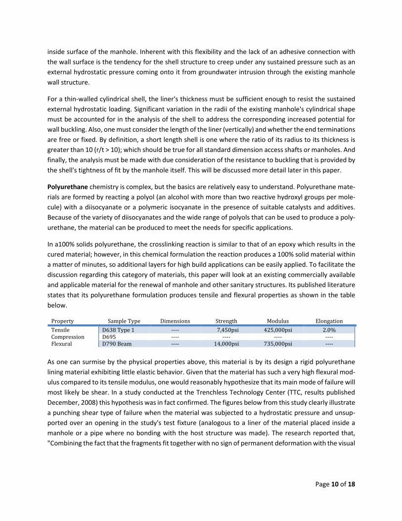
In a100% solids polyurethane, the crosslinking reaction is similar to that of an epoxy which results in the cured material; however, in this chemical formulation the reaction produces a 100% solid material within a matter of minutes, so additional layers for high build applications can be easily applied. To facilitate the discussion regarding this category of materials, this paper will look at an existing commercially available and applicable material for the renewal of manhole and other sanitary structures. Its published literature states that its polyurethane formulation produces tensile and flexural properties as shown in the table below.
Property Sample Type Dimensions Strength Modulus Elongation Tensile D638 Type 1 ---- 7,450psi 425,000psi 2.0% Compression D695 ---- ---- ---- ---- Flexural D790 Beam ---- 14,000psi 735,000psi ----
As one can surmise by the physical properties above, this material is by its design a rigid polyurethane lining material exhibiting little elastic behavior. Given that the material has such a very high flexural mod-ulus compared to its tensile modulus, one would reasonably hypothesize that its main mode of failure will most likely be shear. In a study conducted at the Trenchless Technology Center (TTC, results published December, 2008) this hypothesis was in fact confirmed. The figures below from this study clearly illustrate a punching shear type of failure when the material was subjected to a hydrostatic pressure and unsup-ported over an opening in the study's test fixture (analogous to a liner of the material placed inside a manhole or a pipe where no bonding with the host structure was made). The research reported that, "Combining the fact that the fragments fit together with no sign of permanent deformation with the visual
Page 10 of 18
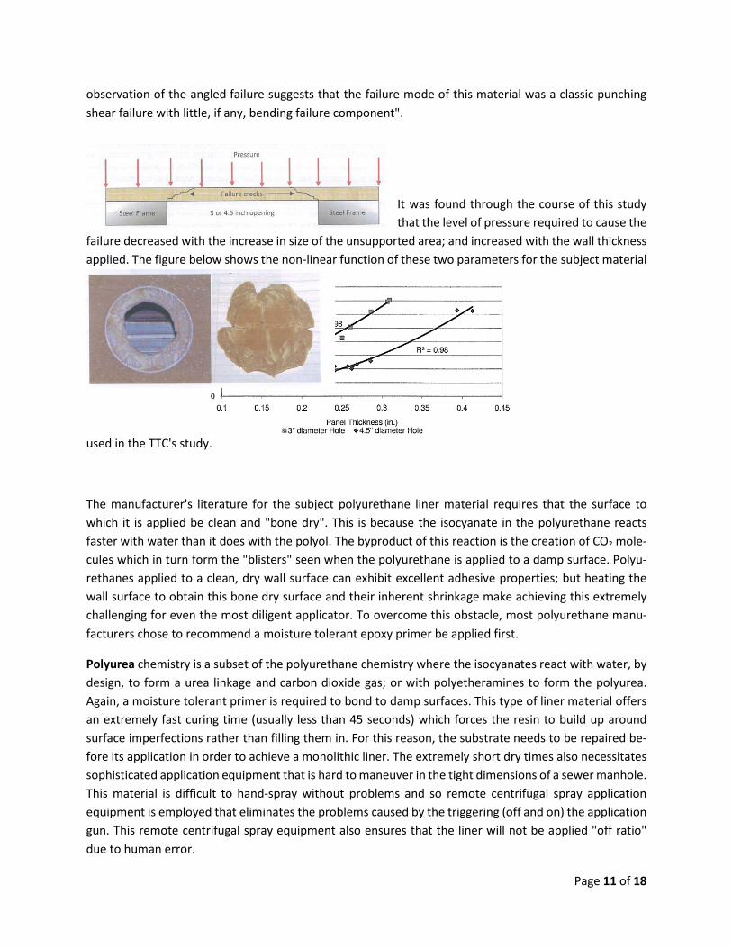
observation of the angled failure suggests that the failure mode of this material was a classic punching shear failure with little, if any, bending failure component".
It was found through the course of this study that the level of pressure required to cause the
failure decreased with the increase in size of the unsupported area; and increased with the wall thickness applied. The figure below shows the non-linear function of these two parameters for the subject material
used in the TTC's study.
The manufacturer's literature for the subject polyurethane liner material requires that the surface to which it is applied be clean and "bone dry". This is because the isocyanate in the polyurethane reacts faster with water than it does with the polyol. The byproduct of this reaction is the creation of CO2 mole-cules which in turn form the "blisters" seen when the polyurethane is applied to a damp surface. Polyu-rethanes applied to a clean, dry wall surface can exhibit excellent adhesive properties; but heating the wall surface to obtain this bone dry surface and their inherent shrinkage make achieving this extremely challenging for even the most diligent applicator. To overcome this obstacle, most polyurethane manu-facturers chose to recommend a moisture tolerant epoxy primer be applied first.
Polyurea chemistry is a subset of the polyurethane chemistry where the isocyanates react with water, by design, to form a urea linkage and carbon dioxide gas; or with polyetheramines to form the polyurea. Again, a moisture tolerant primer is required to bond to damp surfaces. This type of liner material offers an extremely fast curing time (usually less than 45 seconds) which forces the resin to build up around surface imperfections rather than filling them in. For this reason, the substrate needs to be repaired be-fore its application in order to achieve a monolithic liner. The extremely short dry times also necessitates sophisticated application equipment that is hard to maneuver in the tight dimensions of a sewer manhole. This material is difficult to hand-spray without problems and so remote centrifugal spray application equipment is employed that eliminates the problems caused by the triggering (off and on) the application gun. This remote centrifugal spray equipment also ensures that the liner will not be applied "off ratio" due to human error.
Page 11 of 18
Pure polyureas typically have the lowest permeability of the resins discussed in this paper; however, their use in sanitary sewer manholes is problematic because they offer only moderate resistance to concen-trated acids.
Fleury (2013) in his presentation at the annual Texas CMOM workshop on rehabilitation coatings stated that the maximum adhesion achieved in the field with the polyurea materials in his experience was in the range of 200 – 250 psi; compared with a maximum adhesion value for sprayed applied epoxy coatings in the 900 – 1000 psi he saw with the epoxy materials. He went on to recommend that any coating or liner application be required to meet a minimum adhesion level of 250 psi.
REVIEW OF ANY CURRENT DESIGN METHODS BEING EMPLOYED
Presently, the only design method being actively promoted for determining the necessary wall thickness of a coating or liner in a manhole structure is to use the design equations found in the design appendix A of the ASTM standard F1216 for cured in place pipe type lining systems; specifically, equation X1.1 (the partially deteriorated or hydrostatic buckling load only). A research for literature validating this approach revealed only one paper by Bradley (Bradley et al., not published) in which the authors took Timoshenko and Gere's equation for deriving the critical pressure to buckle a thin-walled cylinder subjected to a uni-form pressure along its length and through a series of algebraic manipulations rearranged it to a form that looked the same as equation X1.1 of the referenced design appendix (once one added in the variables for the ovality (C), the enhancement factor (K), and the safety factor (N)). What was glaringly missing from their work was the handling of the portion of Timoshenko and Gere's equation that addressed the number of buckling lobes; (n2 – 1). These unsubstantiated additions and omissions seriously negate the authors' conclusion that equation X1.1 is applicable to a vertically-oriented, cylindrically-shaped, encased thin shell. The use of the empirically derived values for the modifier variables for ovality and structural en-hancement are unsubstantiated by any empirical data when the cylindrical lining is in the vertical orientation.
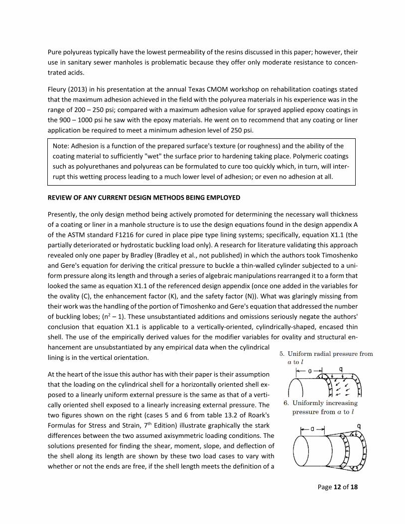
At the heart of the issue this author has with their paper is their assumption that the loading on the cylindrical shell for a horizontally oriented shell ex-posed to a linearly uniform external pressure is the same as that of a verti-cally oriented shell exposed to a linearly increasing external pressure. The two figures shown on the right (cases 5 and 6 from table 13.2 of Roark's Formulas for Stress and Strain, 7th Edition) illustrate graphically the stark differences between the two assumed axisymmetric loading conditions. The solutions presented for finding the shear, moment, slope, and deflection of the shell along its length are shown by these two load cases to vary with whether or not the ends are free, if the shell length meets the definition of a
Note: Adhesion is a function of the prepared surface's texture (or roughness) and the ability of the coating material to sufficiently "wet" the surface prior to hardening taking place. Polymeric coatings such as polyurethanes and polyureas can be formulated to cure too quickly which, in turn, will inter-rupt this wetting process leading to a much lower level of adhesion; or even no adhesion at all.
Page 12 of 18
long or a short shell, along with the other parameters. In this author's opinion, the deformation's slope and the magnitude of the deformation at the bottom are very important design parameters for un-bonded flexible shell-type liners. The long-term water-tightness at the manhole bench depends on the engineer's designing of a sealing area that will remain intact for the designated design life period.
In light of the numerous errors found in the paper by Bradley et al. which invalidate its finding that the ASTM F1216 equation X1.1 is a valid extension of Timoshenko and Gere's buckling solutions for a vertically oriented shell and the accepted solutions within the Roark's reference for the specialized conditions for a liner where the lateral hydrostatic pressure is linearly increasing with depth leads one to the conclusion that one cannot confidently design the wall thickness for a cylindrically-shaped, flexible un-bonded shell type lining placed in a vertically oriented structure using equation X1.1 of the ASTM F1216 design appen-dix A.
LOADING(S) ON BURIED CYLINDRICAL SHAFTS
Analogous to the design of liners for buried pipes, the lateral earth load acting on the existing manhole structure is not going to be the same loading as that required of the structure during its initial installation and soil consolidation period. The initial lateral earth loading is used to predict the stress in the structure from the backfilling process and subsequent subsidence, if any, of the soil over the first twelve months. Presented below is a summarization of the significant amount of study that has gone into cylindrical-shaped vertical shafts that can be applied directly to a cylindrical-shaped manhole structure; which, in turn, can assist the practicing engineer in developing the true design parameters controlling the wall thick-ness design for rehabilitative coatings and liners.
A review of the available technical literature on the subject indicated that numerous research efforts con-ducted to determine the lateral earth pressure acting on cylindrical-shaped shafts and retaining walls has demonstrated that the axisymmetric active earth pressure distribution does not increase linearly with depth as it does in long straight vertical walls under plain strain conditions. Further, these investigative efforts showed that the earth pressure was found, in fact, to decrease rapidly when a small "wall move-ment" was induced. For cohesionless soils the wall movement needed to establish the active earth pres-sure condition was estimated to be 2.5% of the shaft's radius (Tobar and Meguid, ASCE 2011); with the measured reduction in pressure reaching as much as 80% of the initial value, in contrast to a reduction of approximately 40% predicted using the classical earth theories (PH=γhK0; per Rankine).
Geotechnical engineers traditionally have calculated the active earth pressure against vertical shafts and walls using the Rankine theory; where Rankine assumed that the distribution of active earth pressure exerted against the wall would be triangular in shape. However, many experimental results (Tsagareli, 1965; Matsuo et al., 1978; Fang and Ishibashi, 1986) have shown that the distribution of active earth pressure acting on a wall depends on the mode of wall movement and is in fact non-linear; which is dif-ferent from the assumption made by Rankine. This non-linearity of the active earth pressure distribution has been determined to be the result from the horizontal soil arching effects around the shaft (Handy, 1983). In these three dimensional arching effects, the lateral earth pressure acting on a circular type ver-tical shaft is less than that for other types (i.e. square or rectangular shaped shafts). Results reported by
Page 13 of 18
Kim (Kim et al. 2013) obtained from full-scale field testing done on cylindrical shafts confirmed the follow-ing conclusions:
1. The magnitude and distribution of the lateral earth pressure acting on a vertical circular shaft is not linear with increasing depth.
2. The impact of the coupled three-dimensional arching effect significantly reduces the lateral earth pressure acting on the shaft. The maximum reduction is approximately 80%. Therefore, a com-monly used method like the Rankine theory for calculating the lateral pressure on these type structures can substantially overestimate the lateral pressure in real world situations.
3. The arching effect is generally more significant for deep excavation depths than for shallow exca-vation depths.
The take-away from the research cited in the above discussion is that the cylindrically shaped manhole structure over time can lose almost all of the lateral earth pressure that was acting on it at the time of its installation. A seemingly insignificant amount of consolidation of the soil around the manhole enables a significantly distressed (visually speaking) manhole wall to maintain its structural stability by virtue of this reduction in the lateral earth pressure. Renewal of the manhole structure from the inside will not disrupt this current state of equilibrium and thus the most likely load to come onto the liner after its installation is going to be that of any external hydrostatic pressure from groundwater in the soil for the portion of the liner that is below the level of the phreatic surface. To presume that the lateral earth pressure would come onto the liner would only be possible with a significant movement (change in shape) of the manhole wall which is considered highly unlikely.
Therefore, from a practical design perspective, a cylindrical-shaped manhole's structural renewal (or preservation) requires only that the coating or liner be capable of resisting the external hydrostatic pres-sure in the ground surrounding the manhole structure.
MANHOLE REHABILITATION THICKNESS DESIGN
The rational engineering process for a manhole's rehabilitation must begin with an analysis of the current condition state of the remaining wall section, verifying the stability of the soil envelope around the man-hole structure, and determining the issues present that must be addressed in the design of the liner. In all but perhaps the rarest of cases the engineer will find that a condition of stability exists; otherwise, it would be in a dynamic state of collapsing (i.e. falling in). This state of stability implies that the soil-structure interaction system is currently carrying the loads that are acting on it. Once this condition of structural stability of the existing system is concluded, the coating or liner will be designed to address the environ-mental and structural performance requirements it will need to address predicated on its particular per-formance regime.
The order of selection of the material(s) to be used in the rehabilitation should be based first upon the required in situ performance parameters arrived at from the condition assessment process and secondly on the cost of the applicable renewal techniques. Costing of the alternatives must employ the required design life and the estimated service life of the applicable techniques.
Page 14 of 18
Examples of in situ performance parameters are
• Corrosion barrier – A coating or liner is required to isolate the existing manhole from the corrosive elements in the atmosphere or in the fluid flowing in the pipes the manhole supports in order to minimize or arrest any further deterioration of this structural element.
• Infiltration/inflow barrier – A coating or liner is required to arrest further groundwater intrusion either by gravity flow through the soil into openings and voids in the wall structure or by pressure due to the location (elevation) of the phreatic surface (water table).
• Structural enhancement – A coating or liner is required to mend the wall structure. Typically done for brick manholes where a substantial amount of the masonry is missing and it is desired to "fix" the bricks in their current position to assure a long-term renewal is accomplished.
A practical manhole rehabilitation design engineering effort consists of the following steps:
1. Assess the current condition on both the inside and outside of the manhole a. Type of construction b. Level of any wall loss c. Corrosive gases found within the manhole's environment d. pH of the wall surfaces e. Evidence of microbiological corrosion organisms f. Condition of the soil surrounding the manhole structure
i. Noticeable settlement – current or past events ii. Type of backfill material likely used
iii. Signs of the soil of the backfill type on the bench of the manhole g. Observed infiltration through the wall
i. Depth to the phreatic water surface ii. Characterization of any observed water entering through the manhole wall
1. Weeper 2. Dripper 3. Runner 4. Gusher (indicates hydrostatic pressure)
h. Surface conditions i. Live load
ii. Type of pavement iii. Evidence of freeze-thaw action distress
2. Analyze the conditions found and define the needed performance parameters of the rehabilita-tion system(s) to be employed
a. Design life requirements b. Service life expected; how and when will additional work be required
3. Select the applicable rehabilitation solutions based on their estimated wall thickness and; a. Performance parameter requirements b. Cost of the applicable alternatives
i. Design Life requirements
Page 15 of 18
ii. Estimated Service Life of the alternative c. Selection of the most cost-effective rehabilitation solution(s)
4. Confirm the wall thickness parameters of the selected cost-effective alternative(s) 5. Establish the quality assurance testing parameters to ensure the design will be achieved in the
field by the contractor. This is communicated within the technical specifications.
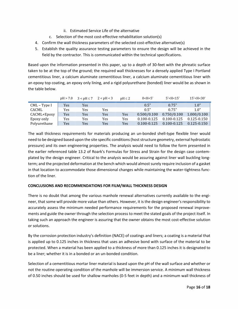
Based upon the information presented in this paper, up to a depth of 30-feet with the phreatic surface taken to be at the top of the ground; the required wall thicknesses for a densely applied Type I Portland cementitious liner, a calcium aluminate cementitious liner, a calcium aluminate cementitious liner with an epoxy top coating, an epoxy only lining, and a rigid polyurethane (bonded) liner would be as shown in the table below.
pH > 7.0 3 < pH ≤ 7 2 < pH < 3 pH ≤ 2 0<H<5' 5'<H<15' 15'<H<30'
CML – Type I Yes Yes 0.5" 0.75" 1.0" CACML Yes Yes Yes 0.5" 0.75" 1.0" CACML+Epoxy Yes Yes Yes Yes 0.500/0.100 0.750/0.100 1.000/0.100 Epoxy only Yes Yes Yes Yes 0.100-0.125 0.100-0.125 0.125-0.150 Polyurethane Yes Yes Yes Yes 0.100-0.125 0.100-0.125 0.125-0.150
The wall thickness requirements for materials producing an un-bonded shell-type flexible liner would need to be designed based upon the site specific conditions (host structure geometry, external hydrostatic pressure) and its own engineering properties. The analysis would need to follow the form presented in the earlier referenced table 13.2 of Roark's Formulas for Stress and Strain for the design case contem-plated by the design engineer. Critical to the analysis would be assuring against liner wall buckling long-term; and the projected deformation at the bench which would almost surely require inclusion of a gasket in that location to accommodate those dimensional changes while maintaining the water-tightness func-tion of the liner.
CONCLUSIONS AND RECOMMENDATIONS FOR FILM/WALL THICKNESS DESIGN
There is no doubt that among the various manhole renewal alternatives currently available to the engi-neer, that some will provide more value than others. However, it is the design engineer's responsibility to accurately assess the minimum needed performance requirements for the proposed renewal improve-ments and guide the owner through the selection process to meet the stated goals of the project itself. In taking such an approach the engineer is assuring that the owner obtains the most cost-effective solution or solutions.
By the corrosion protection industry's definition (NACE) of coatings and liners; a coating is a material that is applied up to 0.125 inches in thickness that uses an adhesive bond with surface of the material to be protected. When a material has been applied to a thickness of more than 0.125 inches it is designated to be a liner; whether it is in a bonded or an un-bonded condition.
Selection of a cementitious mortar liner material is based upon the pH of the wall surface and whether or not the routine operating condition of the manhole will be immersion service. A minimum wall thickness of 0.50 inches should be used for shallow manholes (0-5 feet in depth) and a minimum wall thickness of
Page 16 of 18
0.75 inches should typically suffice for intermediate depth manholes (greater than 5 feet but less than 15 feet in depth); and deeper manholes should typically receive a minimum wall thickness of 1.00 inches. The basis for the measurement of this thickness shall be from the peaks of the roughened surface to the finished level of the mortar surface.
Selection of a polymeric coating material is based upon the material(s) used in the construction of the manhole and its surface profile. For epoxy coatings, a minimum wall thickness of 0.100 inches is recom-mended for new construction (pre-cast concrete) and a minimum thickness of 0.125 inches for renewal of existing structures.
Un-bonded shell-type liners such as cured-in-place thermosetting resin systems using a prefabricated tube material for its placement and spray-on lining systems such as the quick-curing polyurethanes and poly-ureas can be used when the dampness of the wall surface can be brought into compliance with the man-ufacturers' stated requirements (or a suitable moisture tolerant epoxy primer is used). The minimum wall thickness required for this type of liner is based upon the site specific varying geometry of the manhole's cylindrical shape (i.e. local variations in radii), the profile of the hydrostatic loading (it's increasing with depth), and the stiffness of the liner material (relating to its stability and whether failure is by flexural wall buckling or by wall shear). Given the large number of commercially available materials and their varying stiffness properties it is incumbent on the manufacturer of these systems to publish a design guide based upon the wall thickness solution fitting their specific material formulations, the end conditions created by their recommended installation practice, and the type of failure mode that is expected to occur. For ver-tically oriented cylindrical shells, the design case number 6 in the referenced table 13.2 of Roark's Formu-las for Stress and Strain provides a good basis for design for liners whose failure occurs in flexural buckling; however, in its current form this solution needs further refinement to reflect the true buckling resistance considering the casing effect of the existing wall structure.
The engineer in specifying a coating or a liner for the renewal of a cylindrical manhole structure using either a cementitious mortar system or an epoxy resin system need only specify the wall thickness re-quired using the above stated parameters. No site specific wall thickness design is warranted. However, when choosing to use a polymeric lining system where the cylindrical shell is likely to be un-bonded with the host manhole structure; a site specific wall thickness design is required in order to ensure that the stability of the cylinder's geometry is assured for the design life of the stated improvement to the manhole structure.
REFERENCES
Application Guidelines for Raven Lining Systems (2009) downloaded from www.rls
Bradley, S.W., Bradley, W.L., and Johnson, D.H. (written sometime between 1995 and 2000) On the use of ASTM F1216 for the design of manhole liners. Not Published, pp. 1-5.
Fang, Y., Ishibashi, I. (1986) Static earth pressures with various wall movements. ASCE Journal of Ge-otechnical Engineering, 112, 3, pp. 317-333.
Page 17 of 18
Fleury, M., (2013) Rehabilitation coatings – the secret to a successful installation. CMOM 2013 (Austin, TX), 49 slides.
Handy, R.I., (1983). The arch in soil arching. ASCE Journal of Geotechnical Engineering, 111, 3, pp. 302-318.
Kim, K.Y., Lee, D.S., Cho, J., Jeong, S.S., and Lee, S. (2013) The effect of arching pressure on a vertical cir-cular shaft. Tunneling and Underground Space Technology, 37, pp. 10-21.
Matsuo, M., Kenmochi, S., Yagi, H. (1978) Experimental study on earth pressure of retaining wall by field tests. Soil Foundations, 18, 3, pp. 27-41.
Pitt, J.M. (1995) Centrifugal cast mortar for in situ manhole rehabilitation. Conference Proceedings for the 1995 NASTT No-Dig Conference, pp. 1 – 27.
Steward, E.J. (2008) Strength and Deformation testing of rigid polyurethane spray-on coating under in-ternal pressure. A Practicum presented in partial fulfillment of the requirements of the degree Master's of Civil Engineering. College of Engineering and Science, Louisiana Tech University, 28 pages.
Sprayroq US brochure (Version 3 – March 2012) downloaded from www.sprayroq.com
Tobar, T. and Meguid, M.A. (2011) An experimental study of the earth pressure distribution on cylin-drical shafts. ASCE's Journal of Geotechnical and Geoenvironmental Engineering, 137, 11, pp. 1121-1125.
Tsagareli, Z.V. (1965) Experimental investigation of the pressure of a loose medium on retaining walls with a vertical back face and horizontal backfill surface. ASCE Journal of Soil and Mechanical Foundation Engineering, 91, 4, pp. 197-200.
Young, W.C., Budynas, R.G. (2002) Roark's formulas for stress and strain. The seventh edition published by the McGraw-Hill Companies, Inc., pp. 601-607.
Page 18 of 18