Embed Size (px)
Citation preview

Global Edge 2011 Demonstration Guide Last Update: Friday, April 22, 2011
Copyright © 2011 Logic Design Corporation – All Rights Reserved
161 West Wisconsin Avenue, Suite 2E Pewaukee, WI 53072-3468 Phone: 262-695-1300 Fax: 262-695-1313 Web Site: www.ldcglobal.com
1
Demonstration Guide
Confidential
Global Edge® 2011 – Automated Workflow The Power to Succeed in a Global Market
Global Edge® is a Registered Trademark of Logic Design Corporation All Rights Reserved.

Global Edge 2011 Demonstration Guide Last Update: Friday, April 22, 2011
Copyright © 2011 Logic Design Corporation – All Rights Reserved
161 West Wisconsin Avenue, Suite 2E Pewaukee, WI 53072-3468 Phone: 262-695-1300 Fax: 262-695-1313 Web Site: www.ldcglobal.com
2
Table of Contents
Demonstration Outline ......................................................................................................................................................................................................... 3 PowerPoint Presentation .................................................................................................................................................................................................3 1.00: Automated Workflow..............................................................................................................................................................................................3 Open Discussion / Review...............................................................................................................................................................................................3
Demonstration Products Illustrated .................................................................................................................................................................................... 4 Sheet Metal Cabinet Body ...........................................................................................................................................................................................4 Sheet Metal Cabinet Body (Component Drawings) ..................................................................................................................................................4
Web Handler / Utility Cabinet...........................................................................................................................................................................................4 1.00: Automated Workflow .................................................................................................................................................................................................. 5
1.01: Automated CAD Drawing Analysis .......................................................................................................................................................................5 1.02: Automated Routing Generation ............................................................................................................................................................................9 1.03: Automated Sales Quote Generation / Product Configuration..........................................................................................................................19 1.04: Automated CAD Drawing Generation / ERP Interface ......................................................................................................................................26 1.05: Advanced Bill of Materials Management............................................................................................................................................................32

Global Edge 2011 Demonstration Guide Last Update: Friday, April 22, 2011
Copyright © 2011 Logic Design Corporation – All Rights Reserved
161 West Wisconsin Avenue, Suite 2E Pewaukee, WI 53072-3468 Phone: 262-695-1300 Fax: 262-695-1313 Web Site: www.ldcglobal.com
3
Demonstration Outline
Global Edge® 2011 – Automated Workflow software is the world's most advanced quoting system for the sheet metal fabrication industry. Global Edge 2011 – Automated Workflow automates and significantly speeds up the time it normally takes to design, quote and configure custom products. In addition, Global Edge 2011 – Automated Workflow automates the analysis of existing CAD drawings and determines the best and most cost effective routings to produce parts. Global Edge 2011 – Automated Workflow incorporates innovative software technology that helps reduce the cost of short-run products to that of massed produced products by reducing labor intensive design and engineering tasks associated with the quoting process from hours to minutes. The following demonstration outline / timeline that will illustrate the time savings that can be achieved utilizing the Global Edge® 2011 – Automated Workflow: PowerPoint Presentation
Duration: 10 Minutes Elapsed Time: 0:10 1.00: Automated Workflow
1.01: Automated CAD Drawing Analysis 1.02: Automated Routing Generation 1.03: Automated Sales Quote Generation / Product Configuration 1.04: Automated CAD Drawing Generation / ERP Interface 1.05: Advanced Bill of Materials Management
Duration: 30 Minutes Elapsed Time: 0:40 Open Discussion / Review
Duration: 20 Minutes Elapsed Time: 1:00

Global Edge 2011 Demonstration Guide Last Update: Friday, April 22, 2011
Copyright © 2011 Logic Design Corporation – All Rights Reserved
161 West Wisconsin Avenue, Suite 2E Pewaukee, WI 53072-3468 Phone: 262-695-1300 Fax: 262-695-1313 Web Site: www.ldcglobal.com
4
Demonstration Products Illustrated
Sheet Metal Cabinet Body
DEMO PART #: SLD-CABINET-BODY
Sheet Metal Cabinet Body (Component Drawings)
SLD-CABINET-BODY SLD-CABINET-BODY-WRAP SLD-CABINET-BOTTOM SLD-CABINET-TOP SLD-HORZ-DIVIDER
SLD-SPINE-CENTER SLD-SPINE-CORNER-LEFT SLD-SPINE-CORNER-RIGHT SLD-VERT-DIVIDER-BOTTOM SLD-VERT-DIVIDER-TOP
Web Handler / Utility Cabinet
DEMO PART #: SLD-WEB-HANDLER

Global Edge 2011 Demonstration Guide Last Update: Friday, April 22, 2011
Copyright © 2011 Logic Design Corporation – All Rights Reserved
161 West Wisconsin Avenue, Suite 2E Pewaukee, WI 53072-3468 Phone: 262-695-1300 Fax: 262-695-1313 Web Site: www.ldcglobal.com
5
1.00: Automated Workflow
1.01: Automated CAD Drawing Analysis
The Global Edge system includes advanced functionality for rapid and automated configuration of Sales Quotes. This starts with software functionality that automates the process of analyzing a sheet metal part to provide the necessary information to determine how the sheet metal part needs to be fabricated. The following is an illustration of the steps to import a sheet metal part drawing:
1.01.01: Launch "Document Interface" with Desktop Icon:
Document Interface Screen

Global Edge 2011 Demonstration Guide Last Update: Friday, April 22, 2011
Copyright © 2011 Logic Design Corporation – All Rights Reserved
161 West Wisconsin Avenue, Suite 2E Pewaukee, WI 53072-3468 Phone: 262-695-1300 Fax: 262-695-1313 Web Site: www.ldcglobal.com
6
1.01.02: Select “Import” – option then select “Part DXF Files” option – this will display the "Drawing Import" screen:
Drawing Import Screen
The Global Edge – Drawing Import screen provides an easy method to import 2D DXF Sheet Metal Parts. The purpose of this functionality is to import the drawing attribute information into the Global Edge Engineering Data Warehouse for the purpose of Automated Routing Generation. Once a sheet metal part is imported, information such as: Part Height, Part Width, Part Perimeter, Number of Folds, Number of Hems, Number of Cutouts, and Cutout Perimeter is then stored in the Global Edge system. The Global Edge software includes functionality to automatically produce routings and selecting the proper machines on the shop floor based on the capabilities and parameters of the available machines.
Global Edge 2011 Demonstration Guide Last Update: Friday, April 22, 2011
Copyright © 2011 Logic Design Corporation – All Rights Reserved
161 West Wisconsin Avenue, Suite 2E Pewaukee, WI 53072-3468 Phone: 262-695-1300 Fax: 262-695-1313 Web Site: www.ldcglobal.com
7
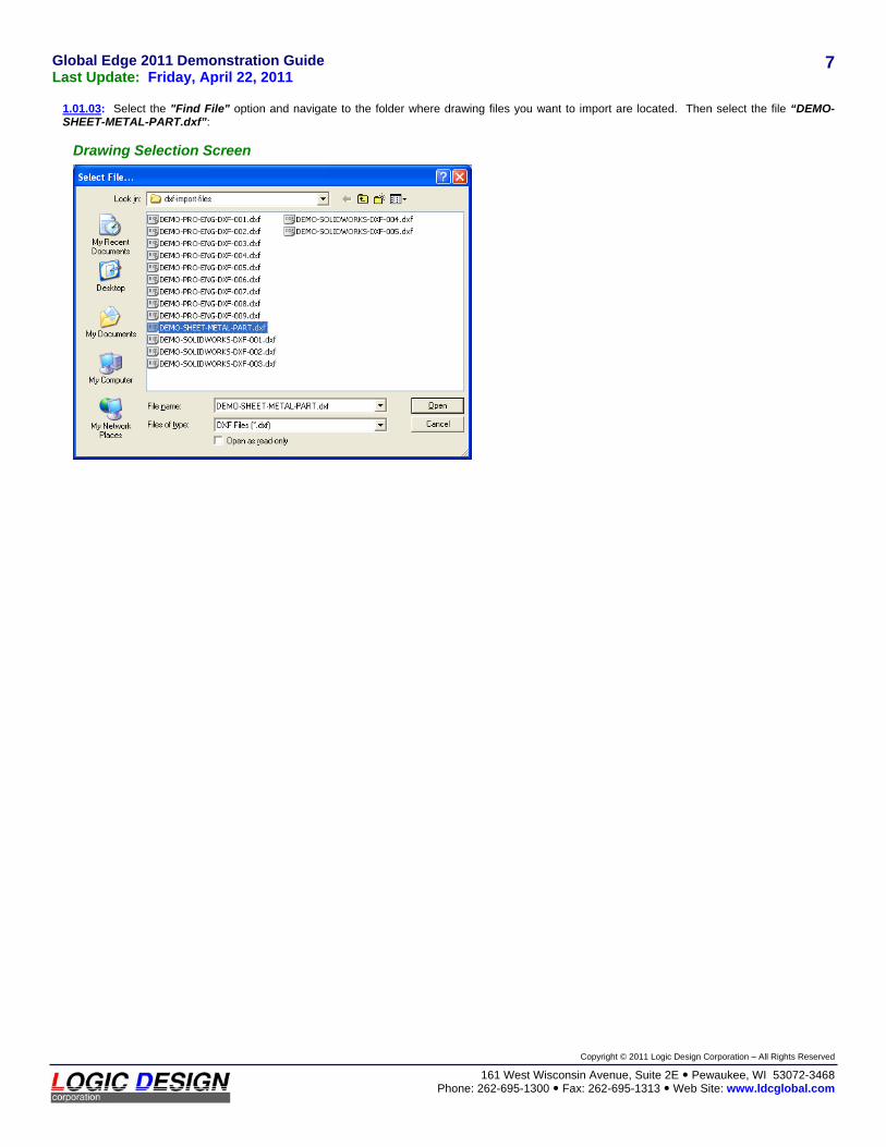
1.01.03: Select the "Find File" option and navigate to the folder where drawing files you want to import are located. Then select the file “DEMO-SHEET-METAL-PART.dxf”:
Drawing Selection Screen

Global Edge 2011 Demonstration Guide Last Update: Friday, April 22, 2011
Copyright © 2011 Logic Design Corporation – All Rights Reserved
161 West Wisconsin Avenue, Suite 2E Pewaukee, WI 53072-3468 Phone: 262-695-1300 Fax: 262-695-1313 Web Site: www.ldcglobal.com
8
1.01.04: On the Global Edge – Drawing Import screen and select “SHT” in “Sheet Metal” field. Select “NS-CRS” in the “Material” field and select “20 GA.” in the “Thick” field, and select “QUOTE-STD” in the “Configuration” field. Then select the “Import” option. Once the drawing importation is complete, an image of the imported DXF file is displayed on the bottom portion of the screen:
Drawing Import Screen
Once the DXF Sheet Metal Parts is imported, information such as: Part Height, Part Width, Part Perimeter, Number of Folds, Number of Hems, Number of Cutouts, and Cutout Perimeter is displayed on the above screen form and stored in the Global Edge system. The Global Edge software includes functionality to automatically produce routings and selecting the proper machines on the shop floor based on the capabilities and parameters of the available machines.

Global Edge 2011 Demonstration Guide Last Update: Friday, April 22, 2011
Copyright © 2011 Logic Design Corporation – All Rights Reserved
161 West Wisconsin Avenue, Suite 2E Pewaukee, WI 53072-3468 Phone: 262-695-1300 Fax: 262-695-1313 Web Site: www.ldcglobal.com
9
1.02: Automated Routing Generation
The Global Edge system includes functionality for Automated Routing Generation. Once attribute information is available for a sheet metal part, the Global Edge software can utilize this information to automatically generate routings and cost roll-ups for the part based on user defined routing configuration rules. This process can be set-up as an interactive user process up to a fully automated process based on shop floor machine parameters and machine availability. The following is an illustration of the steps to generate routings and cost roll-ups:
1.02.01: Once a DXF drawing has been imported using the DXF Drawing Importation process, the next step is to execute the Global Edge Configurator on the imported part. Select the “Engineering” option on the Global Edge Main System Menu:
Main System Menu
1.02.02: This will display the “Engineering Management” menu, and then select the “BOM / Product Configuration” option:
Engineering Management Menu

Global Edge 2011 Demonstration Guide Last Update: Friday, April 22, 2011
Copyright © 2011 Logic Design Corporation – All Rights Reserved
161 West Wisconsin Avenue, Suite 2E Pewaukee, WI 53072-3468 Phone: 262-695-1300 Fax: 262-695-1313 Web Site: www.ldcglobal.com
10
1.02.03: Select the “Find” option followed by the “Part” option and retrieve PART NUMBER (“DEMO-SHEET-METAL-PART”) that was imported in the previous section. Select the “Configurator” option on the PART menu to display the CONFIGURATOR menu. Then select the “Configure” option to display the following menu:
Part Master Screen

Global Edge 2011 Demonstration Guide Last Update: Friday, April 22, 2011
Copyright © 2011 Logic Design Corporation – All Rights Reserved
161 West Wisconsin Avenue, Suite 2E Pewaukee, WI 53072-3468 Phone: 262-695-1300 Fax: 262-695-1313 Web Site: www.ldcglobal.com
11
1.02.04: Prior to execution of the Configurator on the displayed part, the following part dimension values were imported utilizing the “Automated CAD Drawing Analysis” functionality (refer to Page 5):
DIM # DIMENSION NAME DIM TYPE DIM UOM OPTION
1 Part_Length Numeric Inches Imported Value
2 Part_Width Numeric Inches Imported Value
3 Thickness Numeric Inches Imported Value
4 Part_Perimeter Numeric Inches Imported Value
5 Round_Holes Numeric Imported Value
6 Round_Sizes Numeric Imported Value
7 Obround_Holes Numeric Imported Value
8 Obround_Sizes Numeric Imported Value
9 Rectang_Holes Numeric Imported Value
10 Rectang_Sizes Numeric Imported Value
11 Other_Holes Numeric Imported Value
12 Other_Sizes Numeric Imported Value
13 Num_Cutouts Numeric Imported Value
14 Cutout_Perimeter Numeric Inches Imported Value
15 Up_Bends Numeric Imported Value
16 Int_Up_Bends Numeric Imported Value
17 Down_Bends Numeric Imported Value
18 Int_Down_Bends Numeric Imported Value
19 Fold_Count Numeric Imported Value
20 Hem_Count Numeric Imported Value
21 Extrude_Count Numeric Imported Value
22 Bend_Radius Numeric Inches Imported Value
23 Material_Type Character Imported Value
1.02.05: Select the “Yes” option to configure the displayed part. Once the Configurator starts executing, the following “Configurator Dimension” screen form is displayed to answer the first Configurator prompt:
Configurator Dimension Screen

Global Edge 2011 Demonstration Guide Last Update: Friday, April 22, 2011
Copyright © 2011 Logic Design Corporation – All Rights Reserved
161 West Wisconsin Avenue, Suite 2E Pewaukee, WI 53072-3468 Phone: 262-695-1300 Fax: 262-695-1313 Web Site: www.ldcglobal.com
12
1.02.06: The following are the Configurator Prompts that have been defined for demonstration purposes:
DIM # DIMENSION NAME DIM TYPE DIM UOM OPTION
24 Embossed_Part? Character Prompted
1 Yes - (Forces Turret)
2 No
25 Hem_On_Part? Character Prompted
1 Yes - (Forces Press Brake)
2 No
26 Folded_Part_Height Numeric Inches Prompted
27 Incl_Panel_Bender? Character Prompted
1 Yes
2 No - (Forces Press Brake)
28 Edge_Quality: Character Prompted
1 Class-A-Automatic
2 Class-B-Automatic
3 Class-C-Automatic
4 Class-D-Automatic
5 Class-A-Manual
6 Class-B-Manual
7 Class-C-Manual
8 Class-D-Manual
29 Scrat_Free_2_Side? Character Prompted
1 Yes - (Forces Turret)
2 No
30 Deburr_2_Side? Character Prompted
1 Yes
2 No
31 Deburr_After_Form? Character Prompted
1 Yes
2 No
32 Weld_Part? Character Prompted
1 Yes
2 No
33 Paint_Part? Character Prompted
1 Yes
2 No
34 Turret_Laser Character Calculated
1 Turret
2 Laser
35 PressBrk_PanelBend Character Calculated
1 Press-Brake
2 Panel-Bender
3 Both

Global Edge 2011 Demonstration Guide Last Update: Friday, April 22, 2011
Copyright © 2011 Logic Design Corporation – All Rights Reserved
161 West Wisconsin Avenue, Suite 2E Pewaukee, WI 53072-3468 Phone: 262-695-1300 Fax: 262-695-1313 Web Site: www.ldcglobal.com
13
1.02.07: The next step is to select the Optional Components (Hardware Options) that will be included with the part being configured. To select an item on the Options List, enter the letter “X” in the left-most field, and then enter the quantity of the part in the Quantity (QTY) field. When done, select “OK” to continue execution of the Configurator:
Options List Screen
1.02.08: The next step is to select the Optional Components (Purchased Component Options) that will be included with the part being configured. To select an item on the Options List, enter the letter “X” in the left-most field, and then enter the quantity of the part in the Quantity (QTY) field. When done, select “OK” to continue execution of the Configurator:
Options List Screen

Global Edge 2011 Demonstration Guide Last Update: Friday, April 22, 2011
Copyright © 2011 Logic Design Corporation – All Rights Reserved
161 West Wisconsin Avenue, Suite 2E Pewaukee, WI 53072-3468 Phone: 262-695-1300 Fax: 262-695-1313 Web Site: www.ldcglobal.com
14
1.02.09: The next step is to select the Optional Components (Other Charges Options) that will be included with the part being configured. To select an item on the Options List, enter the letter “X” in the left-most field, and then enter the quantity of the part in the Quantity (QTY) field. When done, select “OK” to continue execution of the Configurator:
Options List Screen
1.02.10: The next step in the configuration process is to select the necessary Deburring operations within the defined “Shear-Cut Group”. The Configurator will display the following screen form that includes the Deburring options to select from. Highlight the process you would like to select and then select the “F6” Key to toggle to the sequence order required. You can select multiple processes on this screen form and determine the order of those processes by toggling the Sequence Number (SEQ #) using the “F6” Key. When done selecting the processes you want and the order, select the “OK” option to proceed:
Routing Selection Screen

Global Edge 2011 Demonstration Guide Last Update: Friday, April 22, 2011
Copyright © 2011 Logic Design Corporation – All Rights Reserved
161 West Wisconsin Avenue, Suite 2E Pewaukee, WI 53072-3468 Phone: 262-695-1300 Fax: 262-695-1313 Web Site: www.ldcglobal.com
15
1.02.11: The next step in the configuration process is to select the necessary Forming operations within the defined “Forming Group”. The Configurator will display the following screen form that includes the Forming options to select from. Highlight the process you would like to select and then select the “F6” Key to toggle to the sequence order required. You can select multiple processes on this screen form and determine the order of those processes by toggling the Sequence Number (SEQ #) using the “F6” Key. When done selecting the processes you want and the order, select the “OK” option to proceed:
Routing Selection Screen
1.02.12: As the Configurator executes, the Routing-Selection screen to display the group of Other Operations is displayed. Highlight the process you would like to select and then select the “F6” Key to toggle to the sequence order required. You can select multiple processes on this screen form and determine the order of those processes by toggling the Sequence Number (SEQ #) using the “F6” Key. When done selecting the processes you want and the order, select the “OK” option to proceed:
Routing Selection Screen

Global Edge 2011 Demonstration Guide Last Update: Friday, April 22, 2011
Copyright © 2011 Logic Design Corporation – All Rights Reserved
161 West Wisconsin Avenue, Suite 2E Pewaukee, WI 53072-3468 Phone: 262-695-1300 Fax: 262-695-1313 Web Site: www.ldcglobal.com
16
1.02.13: The next step in the configuration process is to select whether or not the process “FINAL-INSPECT” is included with the part. If this process is included with the part, you will need to enter the Units Per Hour in the “UNITS/HOUR” field. If this process is not included with the part, simply leave the “UNITS/HOUR” field blank. After either entering a factor or leaving the “UNITS/HOUR” field blank, select the “OK” option to continue execution of the Configurator:
Configurator Prompt Screen
1.02.14: The next step in the configuration process is to select whether or not the process “PACKAGE” is included with the part. If this process is included with the part, you will need to enter the Units Per Hour in the “UNITS/HOUR” field. If this process is not included with the part, simply leave the “UNITS/HOUR” field blank. After either entering a factor or leaving the “UNITS/HOUR” field blank, select the “OK” option to continue execution of the Configurator:
Configurator Prompt Screen

Global Edge 2011 Demonstration Guide Last Update: Friday, April 22, 2011
Copyright © 2011 Logic Design Corporation – All Rights Reserved
161 West Wisconsin Avenue, Suite 2E Pewaukee, WI 53072-3468 Phone: 262-695-1300 Fax: 262-695-1313 Web Site: www.ldcglobal.com
17
1.02.15: As the Configurator executes, the Routing-Selection screen to display the group of Other Operations is displayed. Highlight the process you would like to select and then select the “F6” Key to toggle to the sequence order required. You can select multiple processes on this screen form and determine the order of those processes by toggling the Sequence Number (SEQ #) using the “F6” Key. When done selecting the processes you want and the order, select the “OK” option to proceed:
Routing Selection Screen
1.02.16: When the Configurator is done executing, the following screen is displayed:
Configurator Dimension Screen

Global Edge 2011 Demonstration Guide Last Update: Friday, April 22, 2011
Copyright © 2011 Logic Design Corporation – All Rights Reserved
161 West Wisconsin Avenue, Suite 2E Pewaukee, WI 53072-3468 Phone: 262-695-1300 Fax: 262-695-1313 Web Site: www.ldcglobal.com
18
1.02.17: Select the “BOM” option to display the first level of the Bill of Materials of the configured part:
Assembly Components Screen
1.02.18: Return to the PART menu which will then display updated costs for the current part after the Configurator was executed on that part:
Part Master Screen

Global Edge 2011 Demonstration Guide Last Update: Friday, April 22, 2011
Copyright © 2011 Logic Design Corporation – All Rights Reserved
161 West Wisconsin Avenue, Suite 2E Pewaukee, WI 53072-3468 Phone: 262-695-1300 Fax: 262-695-1313 Web Site: www.ldcglobal.com
19
1.03: Automated Sales Quote Generation / Product Configuration
The Global Edge system includes functionality for Automated Sales Quote Generation / Product Configuration. The Global Edge software includes a powerful product configuration engine that makes it possible to quickly produce Sales Quotes for simple-to-complex products based on user definable product configuration rules. The Global Edge software also includes the option of automatic CAD Drawing Generation. This process can be set-up as an interactive user process up to a fully automated process based on the level of defined product configuration rules. The following is an illustration of the steps to generate a sales quote and the automated configuration of a product including cost roll-ups:
1.03.01: Select "Sales & Quote" on Main Menu, and then select “Prospect / Quote Management” option. Select "Find" option, and then retrieve PROSPECT #: "####":
Prospect Maintenance Screen
1.03.02: Select "Sales-Quote" option, and then select “Add” option to generate Sales Quote for displayed prospect record:
Sales Quote Listing Screen

Global Edge 2011 Demonstration Guide Last Update: Friday, April 22, 2011
Copyright © 2011 Logic Design Corporation – All Rights Reserved
161 West Wisconsin Avenue, Suite 2E Pewaukee, WI 53072-3468 Phone: 262-695-1300 Fax: 262-695-1313 Web Site: www.ldcglobal.com
20
1.03.03: Select “Standard Quote Configuration” format on Sales Quote Format Selection screen:
Sales Quote Format Selection Screen
1.03.04: Select "Update" option, and then fill in Sales Quote Header screen with appropriate information:
Sales Quote Header Screen

Global Edge 2011 Demonstration Guide Last Update: Friday, April 22, 2011
Copyright © 2011 Logic Design Corporation – All Rights Reserved
161 West Wisconsin Avenue, Suite 2E Pewaukee, WI 53072-3468 Phone: 262-695-1300 Fax: 262-695-1313 Web Site: www.ldcglobal.com
21
1.03.05: Select "Items" option – then select “Add” option to a quote item to Sales Quote. Enter the Part Number of DXF CAD Drawing that was imported previously imported (“DEMO-SHEET-METAL-PART“). After entering a valid Part Number in the PART # field, fill in the remainder of the screen form with the proper information such as adding to the part description on the six descriptive lines located below the PART # field. Use the TAB key to move to the next data field. In the PRICE Method field, select “Cost-Plus” from the drop-down menu. In the FACTOR field, enter a factor as to what percentage the part should be marked up on the Sales Quote from the cost. Enter a factor of 1.0 if there is no markup on the part. In the QUANTITY field, enter the quantity of parts to include on the Sales Quote:
Sales Quote Item Screen
1.03.06: For multiple price quantities, select the “F10-Quantity” option of right-hand menu to display the following “Quantity-Pricing” screen tab and fill in the various Quantity Prices in the QUANTITY field you want to appear on the Sales Quote:
Sales Quote Quantity Pricing Screen

Global Edge 2011 Demonstration Guide Last Update: Friday, April 22, 2011
Copyright © 2011 Logic Design Corporation – All Rights Reserved
161 West Wisconsin Avenue, Suite 2E Pewaukee, WI 53072-3468 Phone: 262-695-1300 Fax: 262-695-1313 Web Site: www.ldcglobal.com
22
1.03.07: When done on the above screen form, select the “OK” option followed by answering “Yes” to the “Update Record” prompt. This will return you to the previous screen tab. Then select “OK” on “Quote-Item” screen tab which will display the following menu options (QUOTE-ITEM Menu):
Sales Quote Item Screen
1.03.08: Return to QUOTE menu to display the “Quote-Header” screen.
Quote Header Screen

Global Edge 2011 Demonstration Guide Last Update: Friday, April 22, 2011
Copyright © 2011 Logic Design Corporation – All Rights Reserved
161 West Wisconsin Avenue, Suite 2E Pewaukee, WI 53072-3468 Phone: 262-695-1300 Fax: 262-695-1313 Web Site: www.ldcglobal.com
23
1.03.09: Select “Add” option to add an additional quote item to the Sales Quote. Enter PART #: “SLD-CABINET-BODY” to execute Sheet Metal Cabinet Configuration:
Quote Header Screen
1.03.10: Select “OK” – then select “New” option – then enter PART # and description – then select “Yes” to generate the Sheet Metal Cabinet Configuration:
Part Numbering Screen

Global Edge 2011 Demonstration Guide Last Update: Friday, April 22, 2011
Copyright © 2011 Logic Design Corporation – All Rights Reserved
161 West Wisconsin Avenue, Suite 2E Pewaukee, WI 53072-3468 Phone: 262-695-1300 Fax: 262-695-1313 Web Site: www.ldcglobal.com
24
1.03.11: Enter the following Configuration Parameters:
Body_Height: MIN: 024.000000 Inches thru MAX: 060.000000 Inches Interval: 0.010000 Inches Body_Width: MIN: 026.000000 Inches thru MAX: 150.000000 Inches Interval: 0.010000 Inches Body_Depth: MIN: 010.000000 Inches thru MAX: 024.000000 Inches Interval: 0.010000 Inches Post_Height: MIN: 008.000000 Inches thru MAX: 020.000000 Inches Interval: 0.010000 Inches
Configuration Dimension Input Screen
1.03.12: When Configuration is done generating the configured part, answer “Yes” to add configured part as an item the current Sales Quote:
Sales Quote Item Screen

Global Edge 2011 Demonstration Guide Last Update: Friday, April 22, 2011
Copyright © 2011 Logic Design Corporation – All Rights Reserved
161 West Wisconsin Avenue, Suite 2E Pewaukee, WI 53072-3468 Phone: 262-695-1300 Fax: 262-695-1313 Web Site: www.ldcglobal.com
25
SAMPLE SALES QUOTE
QTY. QUOTED UOM DESCRIPTION TAX UNIT QUOTE
5.00
EXTENDED
each
DEMO-SHEET-METAL-PART
N
69.3458
346.73
** PAYMENT SCHEDULE ** QUOTE SUB-TOTAL: SALES TAX:
FREIGHT:
346.73 0.00
75.00
1184
QUOTE # REV #
QUOTE DATE VALID THRU
01/05/2011 02/04/2011
SHIP VIA
BEST WAY
PAY TERMS
NET 30 DAYS
SALES REP.
Michael S. Anderson
TOOL & DIE SUPPLY COMPANY 3455 S. Milford Parkway Chicago, IL 60606-4444 United States of America
TOOL & DIE SUPPLY COMPANY3455 S. Milford Parkway Chicago, IL 60606-4444 United States of America
SUBMITTED TO:
2000 Industrial Blvd. Milwaukee, WI 53201 Phone: 262-695-1300 Fax: 262-695-1313 www.ldcglobal.com
PRICE QUOTATION
CUST ID: CONTACT:
E-MAIL: PHONE:
FAX:
1001 Jim Smith, Purchasing Agent [email protected] 666-444-2433 666-444-2434
PAGE: 001
SHIP TO:
QUOTE TOTAL: $421.73
DAYS2SHIP
10
PART #
Demonstration Sheet Metal Part

Global Edge 2011 Demonstration Guide Last Update: Friday, April 22, 2011
Copyright © 2011 Logic Design Corporation – All Rights Reserved
161 West Wisconsin Avenue, Suite 2E Pewaukee, WI 53072-3468 Phone: 262-695-1300 Fax: 262-695-1313 Web Site: www.ldcglobal.com
26
1.04: Automated CAD Drawing Generation / ERP Interface
The Global Edge system optionally includes a powerful CAD Interface that provides bi-directional integration between your CAD drawings and your ERP / Business System. The Global Edge software provides innovative functionality that will automatically configure and generate 3D CAD Drawings based on user parameters for Simple-to-Complex products. The following is an illustration of the Automated CAD Drawing Generation capabilities incorporated into the Global Edge system:
1.04.01: Select “Documents” option to display the CAD drawings that were generated during the configuration process. Select “Launch” option to launch Assembly Drawing File into CAD Editor:
Document Listing Screen
1.04.02: As CAD Documents are checked out of the Global Edge Document Vault, they are displayed in the below screen:
Document Control Screen

Global Edge 2011 Demonstration Guide Last Update: Friday, April 22, 2011
Copyright © 2011 Logic Design Corporation – All Rights Reserved
161 West Wisconsin Avenue, Suite 2E Pewaukee, WI 53072-3468 Phone: 262-695-1300 Fax: 262-695-1313 Web Site: www.ldcglobal.com
27
1.04.03: Once the CAD Documents are checked out of the Global Edge Document Vault, they are launched into the CAD Editor:
Global Edge CAD Interface

Global Edge 2011 Demonstration Guide Last Update: Friday, April 22, 2011
Copyright © 2011 Logic Design Corporation – All Rights Reserved
161 West Wisconsin Avenue, Suite 2E Pewaukee, WI 53072-3468 Phone: 262-695-1300 Fax: 262-695-1313 Web Site: www.ldcglobal.com
28
1.04.04: Select the Global Edge CAD Interface ”Rebuild” option to rebuild the CAD Template to reflect the Configuration that was generated in previous steps:
Global Edge CAD Interface (Before Drawing Rebuild)
Global Edge CAD Interface (After Drawing Rebuild)

Global Edge 2011 Demonstration Guide Last Update: Friday, April 22, 2011
Copyright © 2011 Logic Design Corporation – All Rights Reserved
161 West Wisconsin Avenue, Suite 2E Pewaukee, WI 53072-3468 Phone: 262-695-1300 Fax: 262-695-1313 Web Site: www.ldcglobal.com
29
1.04.05: Select the Global Edge CAD Interface ”Model Explorer” option to display Part, Drawing, and Dimension information for the displayed CAD Assembly Drawing:
Global Edge CAD Interface (Model Explorer)
The Global Edge CAD Interface includes a Model Explorer that displays the Bill of Materials structure for the current assembly drawing in the CAD software. The Model Explorer provides functionality to update the information contained in the assembly drawing into the Global Edge Engineering Data Warehouse, which in turn is updated in your ERP / Business System. The Model Explorer makes it easy to view and update BOM, Dimension and Document information associated in the current CAD assembly drawing.

Global Edge 2011 Demonstration Guide Last Update: Friday, April 22, 2011
Copyright © 2011 Logic Design Corporation – All Rights Reserved
161 West Wisconsin Avenue, Suite 2E Pewaukee, WI 53072-3468 Phone: 262-695-1300 Fax: 262-695-1313 Web Site: www.ldcglobal.com
30
1.04.06: Select “Quit” option – then select component on Assembly drawing – then select "Global Edge – Browser" option to display ERP profile information for selected Part / Drawing:
Global Edge CAD Interface (Browser Panel)
The Global Edge CAD Interface includes a Browser Panel that allows the CAD Operator to select a CAD Part and view information on that part as it exists in your ERP / Business System.
Global Edge 2011 Demonstration Guide Last Update: Friday, April 22, 2011
Copyright © 2011 Logic Design Corporation – All Rights Reserved
161 West Wisconsin Avenue, Suite 2E Pewaukee, WI 53072-3468 Phone: 262-695-1300 Fax: 262-695-1313 Web Site: www.ldcglobal.com
31
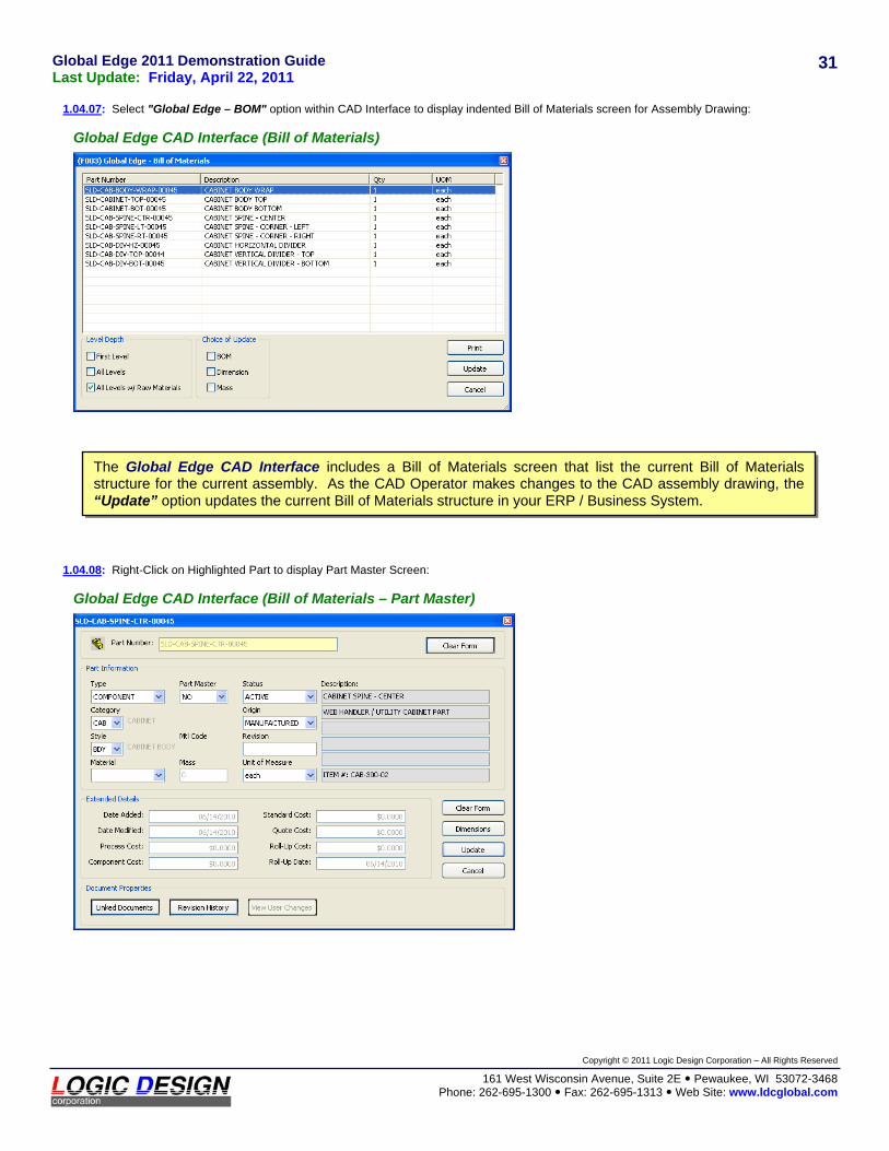
1.04.07: Select "Global Edge – BOM" option within CAD Interface to display indented Bill of Materials screen for Assembly Drawing:
Global Edge CAD Interface (Bill of Materials)
1.04.08: Right-Click on Highlighted Part to display Part Master Screen:
Global Edge CAD Interface (Bill of Materials – Part Master)
The Global Edge CAD Interface includes a Bill of Materials screen that list the current Bill of Materials structure for the current assembly. As the CAD Operator makes changes to the CAD assembly drawing, the “Update” option updates the current Bill of Materials structure in your ERP / Business System.
Global Edge 2011 Demonstration Guide Last Update: Friday, April 22, 2011
Copyright © 2011 Logic Design Corporation – All Rights Reserved
161 West Wisconsin Avenue, Suite 2E Pewaukee, WI 53072-3468 Phone: 262-695-1300 Fax: 262-695-1313 Web Site: www.ldcglobal.com
32
1.05: Advanced Bill of Materials Management
The core of the Global Edge software includes a powerful Bill of Materials system that makes it easy to generate and maintain bill of materials and routings throughout your enterprise. This software functionality simplifies and automates the Engineering and Manufacturing workflow process to help speed up the product cycles from design to final product shipment. The following is an illustration of the advanced Bill of Materials and Routing capabilities incorporated into the Global Edge system:
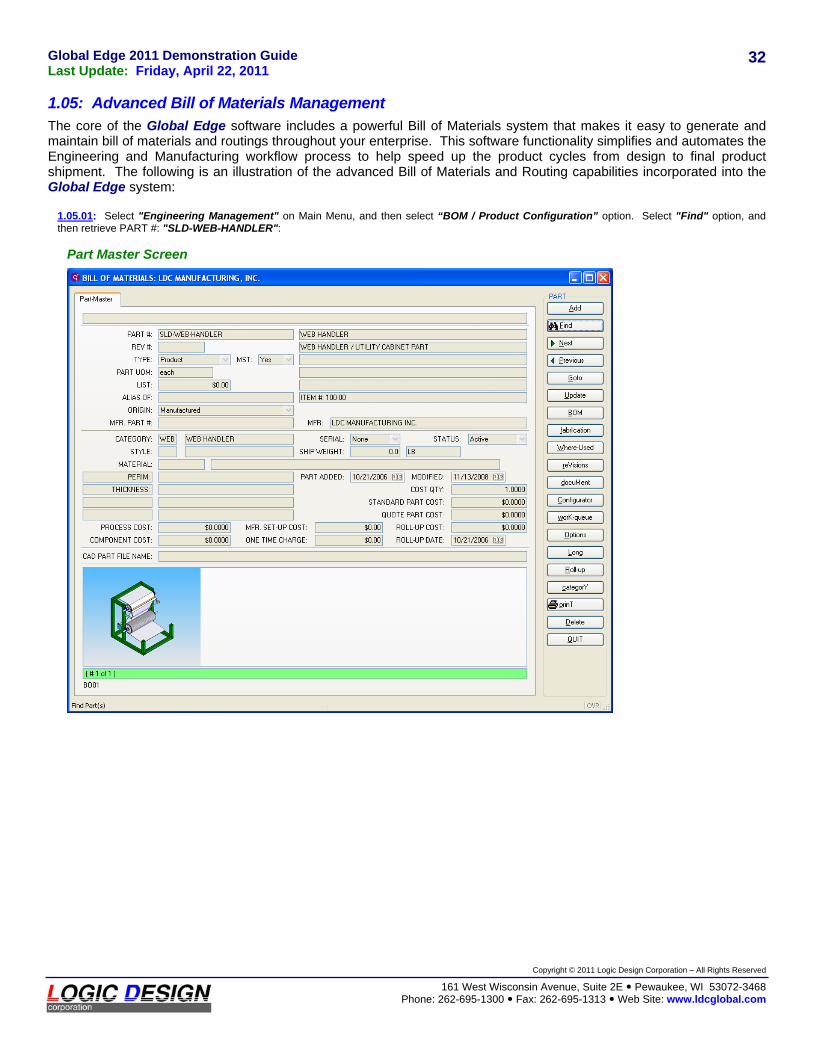
1.05.01: Select "Engineering Management" on Main Menu, and then select “BOM / Product Configuration” option. Select "Find" option, and then retrieve PART #: "SLD-WEB-HANDLER":
Part Master Screen

Global Edge 2011 Demonstration Guide Last Update: Friday, April 22, 2011
Copyright © 2011 Logic Design Corporation – All Rights Reserved
161 West Wisconsin Avenue, Suite 2E Pewaukee, WI 53072-3468 Phone: 262-695-1300 Fax: 262-695-1313 Web Site: www.ldcglobal.com
33
1.05.02: Select "BOM" option to display Bill of Materials assembly components:
BOM Assembly Listing Screen
1.05.03: Select "Routings" option to display Routings for WEB HANDLER ASSEMBLY:
Routing Screen

Global Edge 2011 Demonstration Guide Last Update: Friday, April 22, 2011
Copyright © 2011 Logic Design Corporation – All Rights Reserved
161 West Wisconsin Avenue, Suite 2E Pewaukee, WI 53072-3468 Phone: 262-695-1300 Fax: 262-695-1313 Web Site: www.ldcglobal.com
34
1.05.04: Select "Update" option and select SEQUENCE #: 1 (ASSEMBLE-COMPONENTS) to display routing detailed information:
Routing Detail Screen
1.05.05: Select "Components" option on ROUTING DETAIL menu to display components consumed by currently selected routing operation:
Routing Components Screen
Global Edge 2011 Demonstration Guide Last Update: Friday, April 22, 2011
Copyright © 2011 Logic Design Corporation – All Rights Reserved
161 West Wisconsin Avenue, Suite 2E Pewaukee, WI 53072-3468 Phone: 262-695-1300 Fax: 262-695-1313 Web Site: www.ldcglobal.com
35
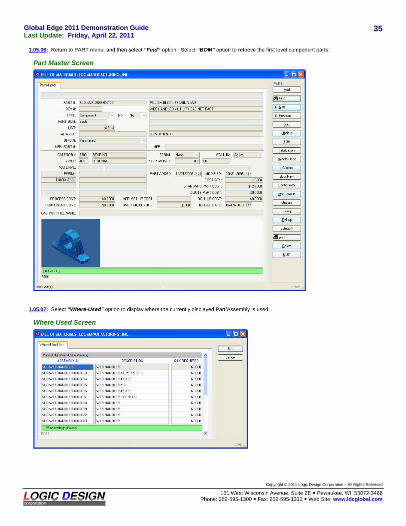
1.05.06: Return to PART menu, and then select “Find” option. Select “BOM” option to retrieve the first level component parts:
Part Master Screen
1.05.07: Select “Where-Used” option to display where the currently displayed Part/Assembly is used:
Where Used Screen

Global Edge 2011 Demonstration Guide Last Update: Friday, April 22, 2011
Copyright © 2011 Logic Design Corporation – All Rights Reserved
161 West Wisconsin Avenue, Suite 2E Pewaukee, WI 53072-3468 Phone: 262-695-1300 Fax: 262-695-1313 Web Site: www.ldcglobal.com
36
1.05.08: Return to PART menu, and then select “Find” option – then select “Dimension” option. Enter CATEGORY (“BRK”) and STYLE (“ANG”) codes to base dimensional search followed by entering search parameters:
Dimension Search Screen
1.05.09: Select “OK” to retrieve part(s) that match Dimension Search Parameters:
Part Master Screen
The Global Edge system provides a wide range of powerful search capabilities that simplifies the process of searching for bill of materials and part information by Part Profile, Dimensional Searches, by Customer, by Vendor, by Employee, by Engineering Changes and Revisions, by Quote, by Sales Order, by Project and Job information, etc.

Global Edge 2011 Demonstration Guide Last Update: Friday, April 22, 2011
Copyright © 2011 Logic Design Corporation – All Rights Reserved
161 West Wisconsin Avenue, Suite 2E Pewaukee, WI 53072-3468 Phone: 262-695-1300 Fax: 262-695-1313 Web Site: www.ldcglobal.com
37
1.05.10: Select “Options” option – then select “Dimensions” option to display dimension values for the displayed Part:
Dimension Listing Screen
1.05.11: Select “Update” option – then select “LENGTH” dimension to display detailed information for selected dimension:
Dimension Edit Screen