Embed Size (px)
Citation preview
https://support.industry.siemens.com/cs/ww/en/view/109486133
FAQ 10/2016
Encoder Configuration for the “Positioning Axis” Technology Function SIMATIC S7-1500, SINAMICS S110/120, SINAMICS G120
Geberparametrierung Entry ID: 109486133, V 1.0, 10/2016 2
S
iem
en
s A
G 2
01
6 A
ll ri
gh
ts r
ese
rve
d
This entry is from the Siemens Industry Online Support. The general terms of use (http://www.siemens.com/terms_of_use) apply.
Security information
Siemens provides products and solutions with industrial security functions that support the secure operation of plants, systems, machines and networks. In order to protect plants, systems, machines and networks against cyber threats, it is necessary to implement – and continuously maintain – a holistic, state-of-the-art industrial security concept. Siemens’ products and solutions only form one element of such a concept. Customer is responsible to prevent unauthorized access to its plants, systems, machines and networks. Systems, machines and components should only be connected to the enterprise network or the internet if and to the extent necessary and with appropriate security measures (e.g. use of firewalls and network segmentation) in place. Additionally, Siemens’ guidance on appropriate security measures should be taken into account. For more information about industrial security, please visit http://www.siemens.com/industrialsecurity.
Siemens’ products and solutions undergo continuous development to make them more secure. Siemens strongly recommends to apply product updates as soon as available and to always use the latest product versions. Use of product versions that are no longer supported, and failure to apply latest updates may increase customer’s exposure to cyber threats. To stay informed about product updates, subscribe to the Siemens Industrial Security RSS Feed under http://www.siemens.com/industrialsecurity.
Geberparametrierung Entry ID: 109486133, V 1.0, 10/2016 3
S
iem
en
s A
G 2
01
6 A
ll ri
gh
ts r
ese
rve
d
Table of Content 1 Encoder Connection on the Drive .................................................................... 4
1.1 Configuring the drive ............................................................................ 4 1.2 Monitoring the encoder data................................................................. 6 1.3 Configuration of the technology object ................................................. 8
2 Encoder Connection to a Technology Module ............................................. 11
2.1 Configuring the technology module .................................................... 11 2.2 Technology module TM Count ........................................................... 11 2.2.1 Parameters of TM Count .................................................................... 11 2.2.2 Monitoring the encoder data............................................................... 13 2.3 Technology module TM PosInput 2 ................................................... 14 2.3.1 Parameters of TM PosInput 2 ............................................................ 14 2.3.2 Monitoring the encoder data............................................................... 15 2.4 Configuration of the technology object ............................................... 17
3 PROFINET/PROFIBUS Encoder ..................................................................... 19
3.1 Configuring the encoder ..................................................................... 19 3.2 Configuration of the technology object ............................................... 20 3.3 Configuration example MC encoder ................................................... 22
4 Technical Information ..................................................................................... 23
4.1 PROFIdrive telegrams ........................................................................ 23 4.2 Encoder values ................................................................................... 24 4.2.1 Control and status words.................................................................... 24 4.2.2 Incremental actual value G1_XIST1 .................................................. 25 4.2.3 Absolute actual value G1_XIST2 ....................................................... 25 4.2.4 Structure of a SSI telegram ................................................................ 26 4.2.5 Parameters of the encoder values in SINAMICS ............................... 27
5 Links & Literature ............................................................................................ 28
1 Encoder Connection on the Drive
Geberparametrierung Entry ID: 109486133, V 1.0, 10/2016 4
S
iem
en
s A
G 2
01
6 A
ll ri
gh
ts r
ese
rve
d
1 Encoder Connection on the Drive For the following SINAMICS drive, there is the option to directly connect an encoder to the drive for the acquisition of speed or position and to evaluate the encoder value in the technology object.
SINAMICS S110/S120
SINAMICS G120 CU250S/CU250D
Note As of TIA Portal V14, the drive or encoder parameters can be automatically transferred into the CPU for SINAMICS drives as of V4.x and PROFIdrive encoders from version A16 onward.
1.1 Configuring the drive
The SINAMICS drive can be configured with the use of the TIA Portal V13 SP1 with the following program:
STARTER for SINAMICS G120 or SINAMICS S110/S120
Start drive for SINAMICS G120
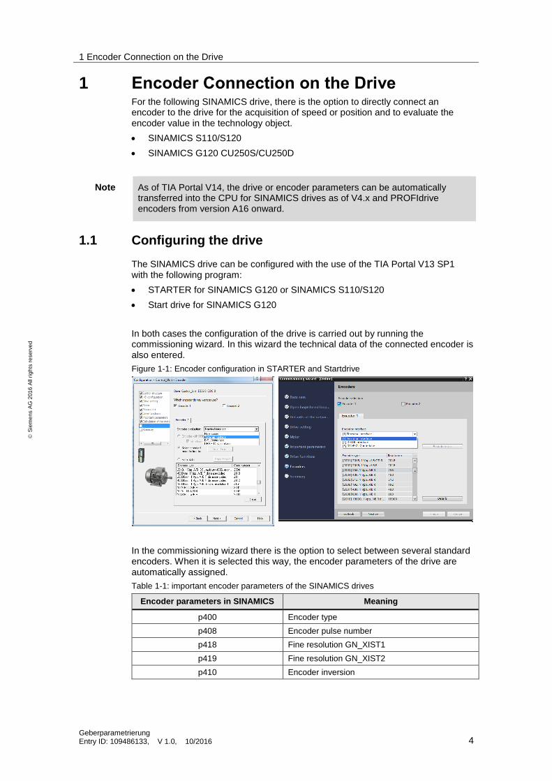
In both cases the configuration of the drive is carried out by running the commissioning wizard. In this wizard the technical data of the connected encoder is also entered.
Figure 1-1: Encoder configuration in STARTER and Startdrive
In the commissioning wizard there is the option to select between several standard encoders. When it is selected this way, the encoder parameters of the drive are automatically assigned.
Table 1-1: important encoder parameters of the SINAMICS drives
Encoder parameters in SINAMICS Meaning
p400 Encoder type
p408 Encoder pulse number
p418 Fine resolution GN_XIST1
p419 Fine resolution GN_XIST2
p410 Encoder inversion
1 Encoder Connection on the Drive
Geberparametrierung Entry ID: 109486133, V 1.0, 10/2016 5
S
iem
en
s A
G 2
01
6 A
ll ri
gh
ts r
ese
rve
d
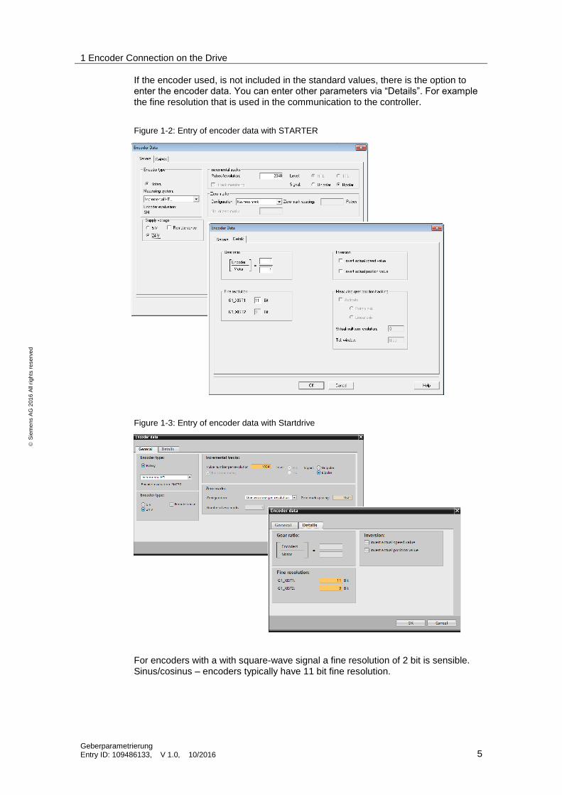
If the encoder used, is not included in the standard values, there is the option to enter the encoder data. You can enter other parameters via “Details”. For example the fine resolution that is used in the communication to the controller.
Figure 1-2: Entry of encoder data with STARTER
Figure 1-3: Entry of encoder data with Startdrive
For encoders with a with square-wave signal a fine resolution of 2 bit is sensible. Sinus/cosinus – encoders typically have 11 bit fine resolution.
1 Encoder Connection on the Drive
Geberparametrierung Entry ID: 109486133, V 1.0, 10/2016 6
S
iem
en
s A
G 2
01
6 A
ll ri
gh
ts r
ese
rve
d
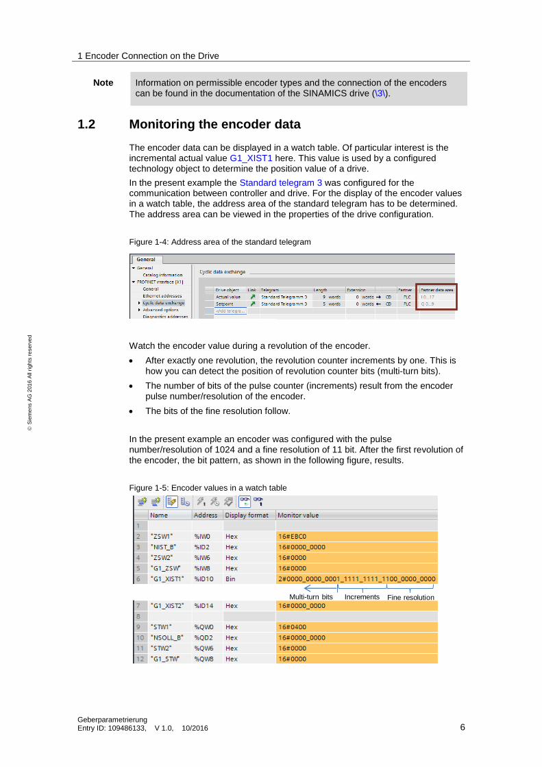
Note Information on permissible encoder types and the connection of the encoders can be found in the documentation of the SINAMICS drive (\3\).
1.2 Monitoring the encoder data
The encoder data can be displayed in a watch table. Of particular interest is the incremental actual value G1_XIST1 here. This value is used by a configured technology object to determine the position value of a drive.
In the present example the Standard telegram 3 was configured for the communication between controller and drive. For the display of the encoder values in a watch table, the address area of the standard telegram has to be determined. The address area can be viewed in the properties of the drive configuration.
Figure 1-4: Address area of the standard telegram
Watch the encoder value during a revolution of the encoder.
After exactly one revolution, the revolution counter increments by one. This is how you can detect the position of revolution counter bits (multi-turn bits).
The number of bits of the pulse counter (increments) result from the encoder pulse number/resolution of the encoder.
The bits of the fine resolution follow.
In the present example an encoder was configured with the pulse number/resolution of 1024 and a fine resolution of 11 bit. After the first revolution of the encoder, the bit pattern, as shown in the following figure, results.
Figure 1-5: Encoder values in a watch table
Fine resolutionIncrementsMulti-turn bits
1 Encoder Connection on the Drive
Geberparametrierung Entry ID: 109486133, V 1.0, 10/2016 7
S
iem
en
s A
G 2
01
6 A
ll ri
gh
ts r
ese
rve
d
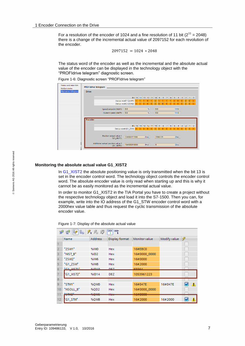
For a resolution of the encoder of 1024 and a fine resolution of 11 bit (211
= 2048) there is a change of the incremental actual value of 2097152 for each revolution of the encoder.
2097152 = 1024 ∗ 2048
The status word of the encoder as well as the incremental and the absolute actual value of the encoder can be displayed in the technology object with the “PROFIdrive telegram” diagnostic screen.
Figure 1-6: Diagnostic screen “PROFIdrive telegram”
Monitoring the absolute actual value G1_XIST2
In G1_XIST2 the absolute positioning value is only transmitted when the bit 13 is set in the encoder control word. The technology object controls the encoder control word. The absolute encoder value is only read when starting up and this is why it cannot be as easily monitored as the incremental actual value.
In order to monitor G1_XIST2 in the TIA Portal you have to create a project without the respective technology object and load it into the S7-1500. Then you can, for example, write into the IO address of the G1_STW encoder control word with a 2000hex value table and thus request the cyclic transmission of the absolute encoder value.
Figure 1-7: Display of the absolute actual value
1 Encoder Connection on the Drive
Geberparametrierung Entry ID: 109486133, V 1.0, 10/2016 8
S
iem
en
s A
G 2
01
6 A
ll ri
gh
ts r
ese
rve
d
1.3 Configuration of the technology object
The configuration of the technology object is divided into several areas. The encoder is configured in the “Hardware interface” section.
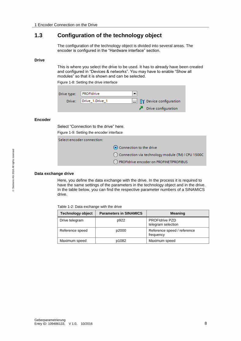
Drive
This is where you select the drive to be used. It has to already have been created and configured in “Devices & networks”. You may have to enable “Show all modules” so that it is shown and can be selected.
Figure 1-8: Setting the drive interface
Encoder
Select “Connection to the drive” here.
Figure 1-9: Setting the encoder interface
Data exchange drive
Here, you define the data exchange with the drive. In the process it is required to have the same settings of the parameters in the technology object and in the drive. In the table below, you can find the respective parameter numbers of a SINAMICS drive.
Table 1-2: Data exchange with the drive
Technology object Parameters in SINAMICS Meaning
Drive telegram p922 PROFIdrive PZD telegram selection
Reference speed p2000 Reference speed / reference frequency
Maximum speed p1082 Maximum speed
1 Encoder Connection on the Drive
Geberparametrierung Entry ID: 109486133, V 1.0, 10/2016 9
S
iem
en
s A
G 2
01
6 A
ll ri
gh
ts r
ese
rve
d
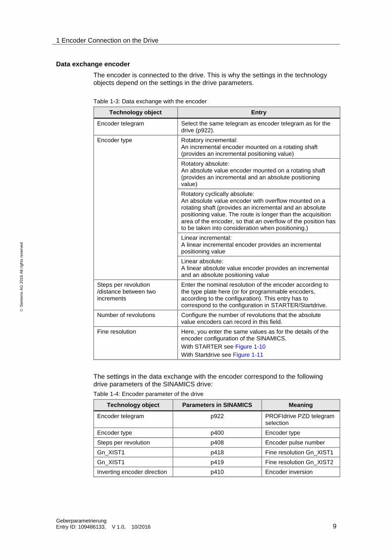
Data exchange encoder
The encoder is connected to the drive. This is why the settings in the technology objects depend on the settings in the drive parameters.
Table 1-3: Data exchange with the encoder
Technology object Entry
Encoder telegram Select the same telegram as encoder telegram as for the drive (p922).
Encoder type Rotatory incremental: An incremental encoder mounted on a rotating shaft (provides an incremental positioning value)
Rotatory absolute: An absolute value encoder mounted on a rotating shaft (provides an incremental and an absolute positioning value)
Rotatory cyclically absolute: An absolute value encoder with overflow mounted on a rotating shaft (provides an incremental and an absolute positioning value. The route is longer than the acquisition area of the encoder, so that an overflow of the position has to be taken into consideration when positioning.)
Linear incremental: A linear incremental encoder provides an incremental positioning value
Linear absolute: A linear absolute value encoder provides an incremental and an absolute positioning value
Steps per revolution /distance between two increments
Enter the nominal resolution of the encoder according to the type plate here (or for programmable encoders, according to the configuration). This entry has to correspond to the configuration in STARTER/Startdrive.
Number of revolutions Configure the number of revolutions that the absolute value encoders can record in this field.
Fine resolution Here, you enter the same values as for the details of the encoder configuration of the SINAMICS.
With STARTER see Figure 1-10
With Startdrive see Figure 1-11
The settings in the data exchange with the encoder correspond to the following drive parameters of the SINAMICS drive:
Table 1-4: Encoder parameter of the drive
Technology object Parameters in SINAMICS Meaning
Encoder telegram p922 PROFIdrive PZD telegram selection
Encoder type p400 Encoder type
Steps per revolution p408 Encoder pulse number
Gn_XIST1 p418 Fine resolution Gn_XIST1
Gn_XIST1 p419 Fine resolution Gn_XIST2
Inverting encoder direction p410 Encoder inversion
1 Encoder Connection on the Drive
Geberparametrierung Entry ID: 109486133, V 1.0, 10/2016 10
S
iem
en
s A
G 2
01
6 A
ll ri
gh
ts r
ese
rve
d
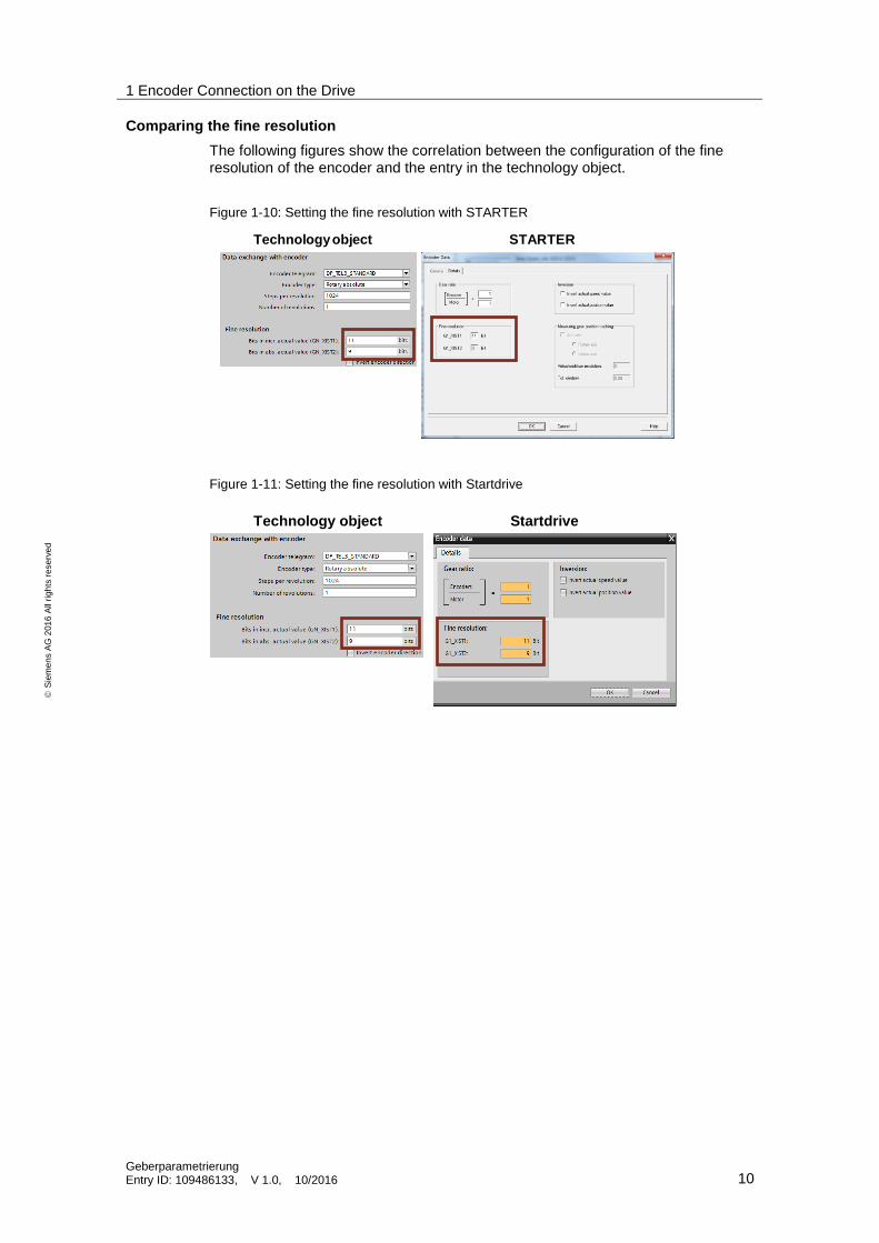
Comparing the fine resolution
The following figures show the correlation between the configuration of the fine resolution of the encoder and the entry in the technology object.
Figure 1-10: Setting the fine resolution with STARTER
Technology object STARTER
Figure 1-11: Setting the fine resolution with Startdrive
Technology object Startdrive
2 Encoder Connection to a Technology Module
Geberparametrierung Entry ID: 109486133, V 1.0, 10/2016 11
S
iem
en
s A
G 2
01
6 A
ll ri
gh
ts r
ese
rve
d
2 Encoder Connection to a Technology Module You can operate the technology module centrally on a SIMATIC S7-1500 or in a distributed I/O. Use the TM Count 2x24V or TM PosInput 2 technology module for the connection of an incremental encoder. Only use the TM PosInput 2 technology module for the connection of an absolute value encoder.
Note Information on the connection and configuration of the technology module can be found in the device manuals.
Technology module TM Count 2x24V (\5\)
Technology module TM PosInput 2 (\6\)
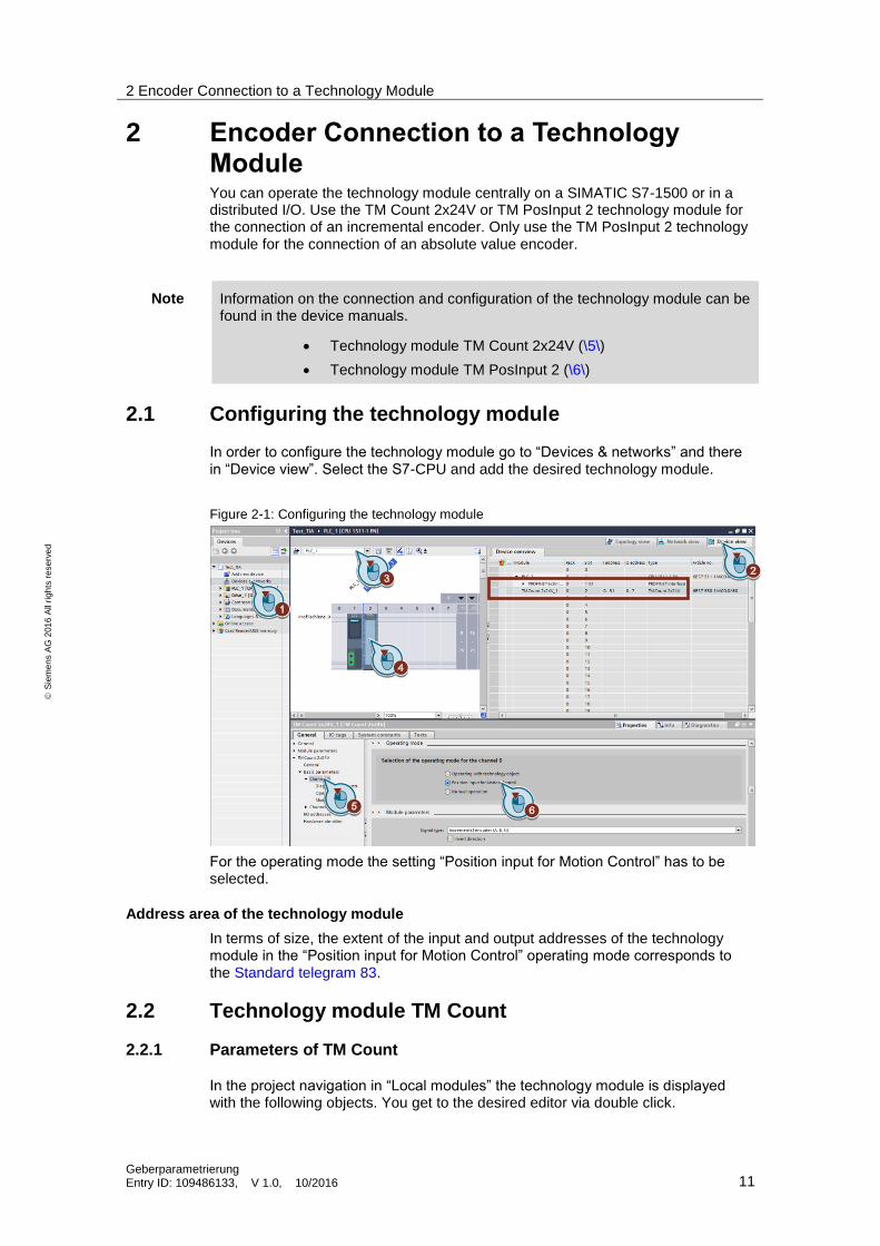
2.1 Configuring the technology module
In order to configure the technology module go to “Devices & networks” and there in “Device view”. Select the S7-CPU and add the desired technology module.
Figure 2-1: Configuring the technology module
For the operating mode the setting “Position input for Motion Control” has to be selected.
Address area of the technology module
In terms of size, the extent of the input and output addresses of the technology module in the “Position input for Motion Control” operating mode corresponds to the Standard telegram 83.
2.2 Technology module TM Count
2.2.1 Parameters of TM Count
In the project navigation in “Local modules” the technology module is displayed with the following objects. You get to the desired editor via double click.
2 Encoder Connection to a Technology Module
Geberparametrierung Entry ID: 109486133, V 1.0, 10/2016 12
S
iem
en
s A
G 2
01
6 A
ll ri
gh
ts r
ese
rve
d
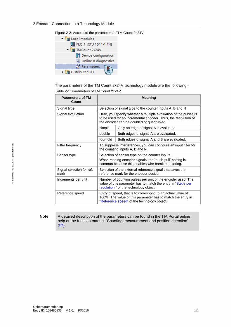
Figure 2-2: Access to the parameters of TM Count 2x24V
The parameters of the TM Count 2x24V technology module are the following:
Table 2-1: Parameters of TM Count 2x24V
Parameters of TM Count
Meaning
Signal type Selection of signal type to the counter inputs A, B and N
Signal evaluation Here, you specify whether a multiple evaluation of the pulses is to be used for an incremental encoder. Thus, the resolution of the encoder can be doubled or quadrupled.
simple Only an edge of signal A is evaluated
double Both edges of signal A are evaluated.
four fold Both edges of signal A and B are evaluated.
Filter frequency To suppress interferences, you can configure an input filter for the counting inputs A, B and N.
Sensor type Selection of sensor type on the counter inputs.
When reading encoder signals, the “push-pull” setting is common because this enables wire break monitoring.
Signal selection for ref. mark
Selection of the external reference signal that saves the reference mark for the encoder position.
Increments per unit Number of counting pulses per unit of the encoder used. The value of this parameter has to match the entry in “Steps per revolution ” of the technology object.
Reference speed Entry of speed, that is to correspond to an actual value of 100%. The value of this parameter has to match the entry in “Reference speed” of the technology object.
Note A detailed description of the parameters can be found in the TIA Portal online help or the function manual “Counting, measurement and position detection” (\7\).
2 Encoder Connection to a Technology Module
Geberparametrierung Entry ID: 109486133, V 1.0, 10/2016 13
S
iem
en
s A
G 2
01
6 A
ll ri
gh
ts r
ese
rve
d
2.2.2 Monitoring the encoder data
The encoder data can be displayed in a watch table. Of particular interest is the incremental actual value G1_XIST1 here. This value is used by a configured technology object to determine the position value of a drive.
In the present example the Standard telegram 83 has been configured for the communication between controller and the TM Count technology module. For the display of the encoder values in a watch table, the address area of the standard telegram has to be determined. The address area is specified in the configuration of the technology module. (see Figure 2-1: Configuring the technology module)
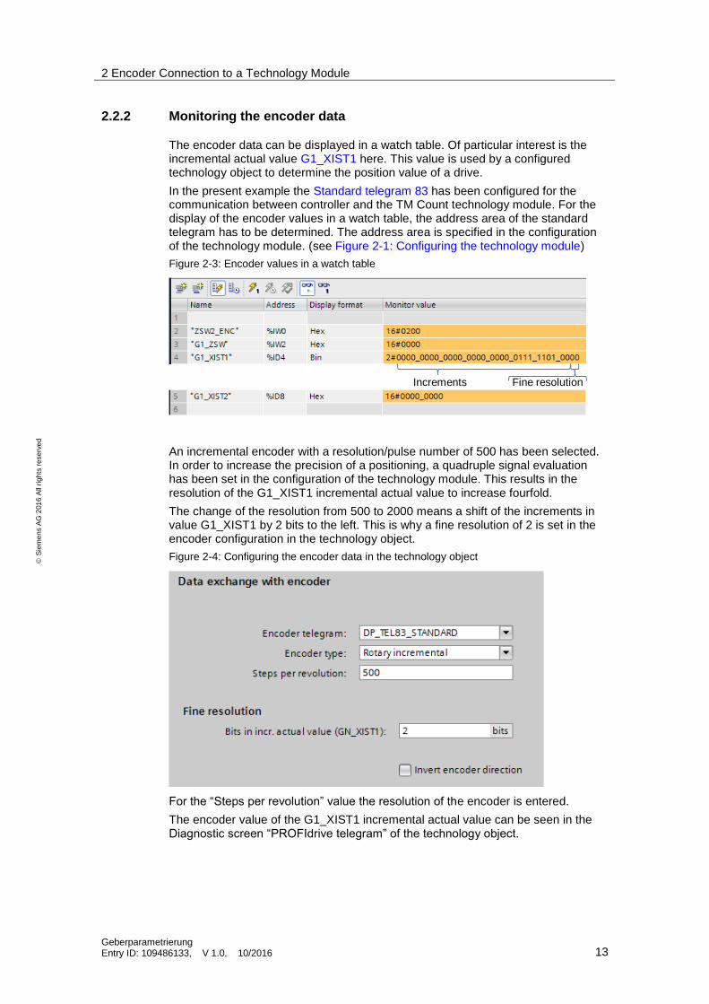
Figure 2-3: Encoder values in a watch table
Fine resolutionIncrements
An incremental encoder with a resolution/pulse number of 500 has been selected. In order to increase the precision of a positioning, a quadruple signal evaluation has been set in the configuration of the technology module. This results in the resolution of the G1_XIST1 incremental actual value to increase fourfold.
The change of the resolution from 500 to 2000 means a shift of the increments in value G1_XIST1 by 2 bits to the left. This is why a fine resolution of 2 is set in the encoder configuration in the technology object.
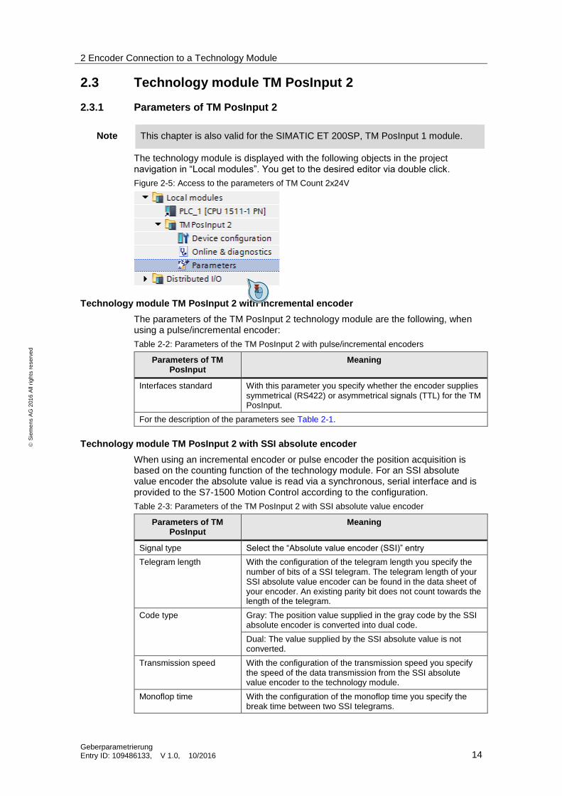
Figure 2-4: Configuring the encoder data in the technology object
For the “Steps per revolution” value the resolution of the encoder is entered.
The encoder value of the G1_XIST1 incremental actual value can be seen in the Diagnostic screen “PROFIdrive telegram” of the technology object.
2 Encoder Connection to a Technology Module
Geberparametrierung Entry ID: 109486133, V 1.0, 10/2016 14
S
iem
en
s A
G 2
01
6 A
ll ri
gh
ts r
ese
rve
d
2.3 Technology module TM PosInput 2
2.3.1 Parameters of TM PosInput 2
Note This chapter is also valid for the SIMATIC ET 200SP, TM PosInput 1 module.
The technology module is displayed with the following objects in the project navigation in “Local modules”. You get to the desired editor via double click.
Figure 2-5: Access to the parameters of TM Count 2x24V
Technology module TM PosInput 2 with incremental encoder
The parameters of the TM PosInput 2 technology module are the following, when using a pulse/incremental encoder:
Table 2-2: Parameters of the TM PosInput 2 with pulse/incremental encoders
Parameters of TM PosInput
Meaning
Interfaces standard With this parameter you specify whether the encoder supplies symmetrical (RS422) or asymmetrical signals (TTL) for the TM PosInput.
For the description of the parameters see Table 2-1.
Technology module TM PosInput 2 with SSI absolute encoder
When using an incremental encoder or pulse encoder the position acquisition is based on the counting function of the technology module. For an SSI absolute value encoder the absolute value is read via a synchronous, serial interface and is provided to the S7-1500 Motion Control according to the configuration.
Table 2-3: Parameters of the TM PosInput 2 with SSI absolute value encoder
Parameters of TM PosInput
Meaning
Signal type Select the “Absolute value encoder (SSI)” entry
Telegram length With the configuration of the telegram length you specify the number of bits of a SSI telegram. The telegram length of your SSI absolute value encoder can be found in the data sheet of your encoder. An existing parity bit does not count towards the length of the telegram.
Code type Gray: The position value supplied in the gray code by the SSI absolute encoder is converted into dual code.
Dual: The value supplied by the SSI absolute value is not converted.
Transmission speed With the configuration of the transmission speed you specify the speed of the data transmission from the SSI absolute value encoder to the technology module.
Monoflop time With the configuration of the monoflop time you specify the break time between two SSI telegrams.
2 Encoder Connection to a Technology Module
Geberparametrierung Entry ID: 109486133, V 1.0, 10/2016 15
S
iem
en
s A
G 2
01
6 A
ll ri
gh
ts r
ese
rve
d
Parameters of TM PosInput
Meaning
Parity With the configuration of the parity you specify whether the SSI absolute value encoder transfers a parity bit.
Bit number LSB With this parameter you specify the bit number of the LSB (Least significant Bit) of the position value in the telegram of the SSI absolute value encoder.
Bit number MSB With this parameter you specify the bit number of the MSB (Most significant Bit) of the position value in the telegram of the SSI absolute value encoder.
Increments per unit With this parameter you specify the number of increments that the SSI absolute value encoder supplies per revolution.
Reference speed Entry of speed, that is to correspond to an actual value of 100%. The value of this parameter has to match the entry in “Reference speed” of the technology object.
Note A detailed description of the parameters can be found in the TIA Portal online help or the function manual “Counting, measurement and position detection” (\7\).
Bit numbers LSB / MSB of the position value (SSI encoder)
With the parameters of the LSB (Least significant Bit) and the MSB (Most significant Bit) you specify the length and the position of the position value in the telegram of the SSI absolute value encoder.
2.3.2 Monitoring the encoder data
The encoder data can be displayed in a watch table. Of particular interest is the incremental actual value G1_XIST1 here. This value is used by a configured technology object to determine the position value of a drive.
In the current example the Standard telegram 83 has been configured for the communication between controller and the TM PosInput technology module. For the display of the encoder values in a watch table, the address area of the standard telegram has to be determined. The address area is specified in the configuration of the technology module. (see Figure 2-1: Configuring the technology module)
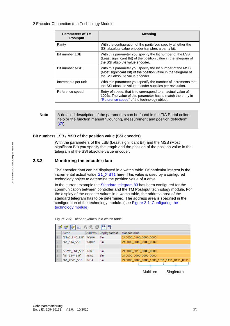
Figure 2-6: Encoder values in a watch table
SingleturnMultiturn
2 Encoder Connection to a Technology Module
Geberparametrierung Entry ID: 109486133, V 1.0, 10/2016 16
S
iem
en
s A
G 2
01
6 A
ll ri
gh
ts r
ese
rve
d
Example
An SSI – absolute value encoder with a resolution of 25 bit is used. The number of the single-turn bits can be easily determined by monitoring the SSI telegram in watch table. In the area of the single-turn bit any possible value is reached once during a revolution of the encoder.
The number of bits in the multi-turn and single-turn area result in the number of steps for the encoder configuration in the technology object.
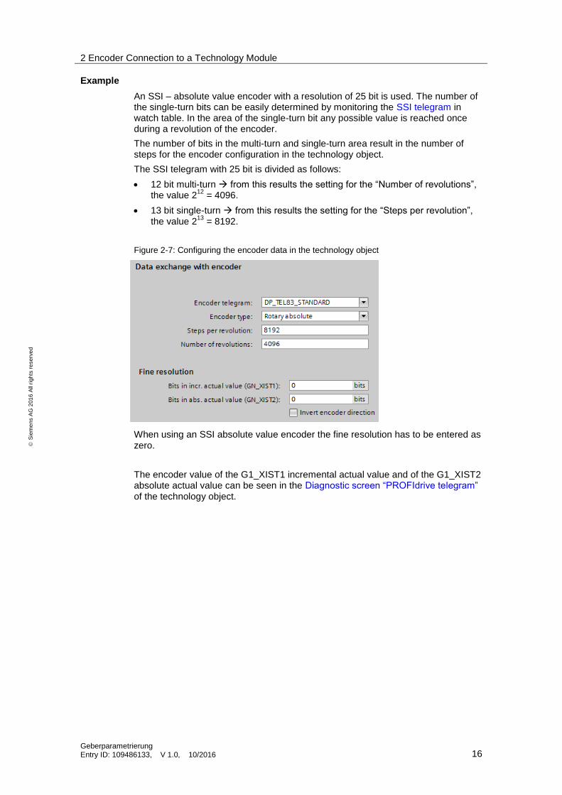
The SSI telegram with 25 bit is divided as follows:
12 bit multi-turn from this results the setting for the “Number of revolutions”, the value 2
12 = 4096.
13 bit single-turn from this results the setting for the “Steps per revolution”, the value 2
13 = 8192.
Figure 2-7: Configuring the encoder data in the technology object
When using an SSI absolute value encoder the fine resolution has to be entered as zero.
The encoder value of the G1_XIST1 incremental actual value and of the G1_XIST2 absolute actual value can be seen in the Diagnostic screen “PROFIdrive telegram” of the technology object.
2 Encoder Connection to a Technology Module
Geberparametrierung Entry ID: 109486133, V 1.0, 10/2016 17
S
iem
en
s A
G 2
01
6 A
ll ri
gh
ts r
ese
rve
d
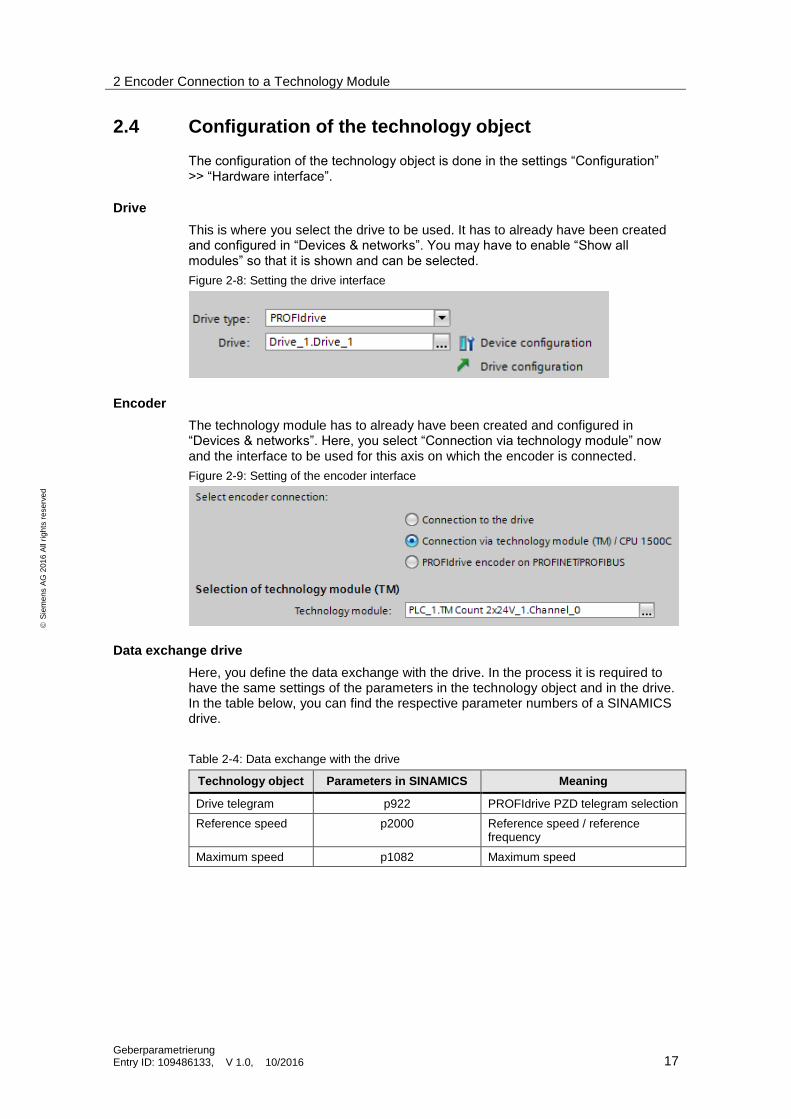
2.4 Configuration of the technology object
The configuration of the technology object is done in the settings “Configuration” >> “Hardware interface”.
Drive
This is where you select the drive to be used. It has to already have been created and configured in “Devices & networks”. You may have to enable “Show all modules” so that it is shown and can be selected.
Figure 2-8: Setting the drive interface
Encoder
The technology module has to already have been created and configured in “Devices & networks”. Here, you select “Connection via technology module” now and the interface to be used for this axis on which the encoder is connected.
Figure 2-9: Setting of the encoder interface
Data exchange drive
Here, you define the data exchange with the drive. In the process it is required to have the same settings of the parameters in the technology object and in the drive. In the table below, you can find the respective parameter numbers of a SINAMICS drive.
Table 2-4: Data exchange with the drive
Technology object Parameters in SINAMICS Meaning
Drive telegram p922 PROFIdrive PZD telegram selection
Reference speed p2000 Reference speed / reference frequency
Maximum speed p1082 Maximum speed
2 Encoder Connection to a Technology Module
Geberparametrierung Entry ID: 109486133, V 1.0, 10/2016 18
S
iem
en
s A
G 2
01
6 A
ll ri
gh
ts r
ese
rve
d
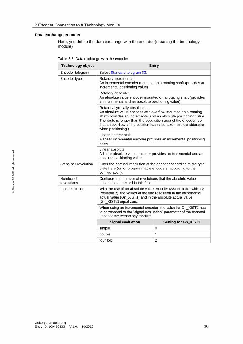
Data exchange encoder
Here, you define the data exchange with the encoder (meaning the technology module).
Table 2-5: Data exchange with the encoder
Technology object Entry
Encoder telegram Select Standard telegram 83.
Encoder type Rotatory incremental: An incremental encoder mounted on a rotating shaft (provides an incremental positioning value)
Rotatory absolute: An absolute value encoder mounted on a rotating shaft (provides an incremental and an absolute positioning value)
Rotatory cyclically absolute: An absolute value encoder with overflow mounted on a rotating shaft (provides an incremental and an absolute positioning value. The route is longer than the acquisition area of the encoder, so that an overflow of the position has to be taken into consideration when positioning.)
Linear incremental: A linear incremental encoder provides an incremental positioning value
Linear absolute: A linear absolute value encoder provides an incremental and an absolute positioning value
Steps per revolution Enter the nominal resolution of the encoder according to the type plate here (or for programmable encoders, according to the configuration).
Number of revolutions
Configure the number of revolutions that the absolute value encoders can record in this field.
Fine resolution With the use of an absolute value encoder (SSI encoder with TM PosInput 2), the values of the fine resolution in the incremental actual value (Gn_XIST1) and in the absolute actual value (Gn_XIST2) equal zero.
When using an incremental encoder, the value for Gn_XIST1 has to correspond to the “signal evaluation” parameter of the channel used for the technology module.
Signal evaluation Setting for Gn_XIST1
simple 0
double 1
four fold 2
3 PROFINET/PROFIBUS Encoder
Geberparametrierung Entry ID: 109486133, V 1.0, 10/2016 19
S
iem
en
s A
G 2
01
6 A
ll ri
gh
ts r
ese
rve
d
3 PROFINET/PROFIBUS Encoder The PROFINET/PROFIBUS-capable encoders transfer the information gained directly in the telegram to the technology object.
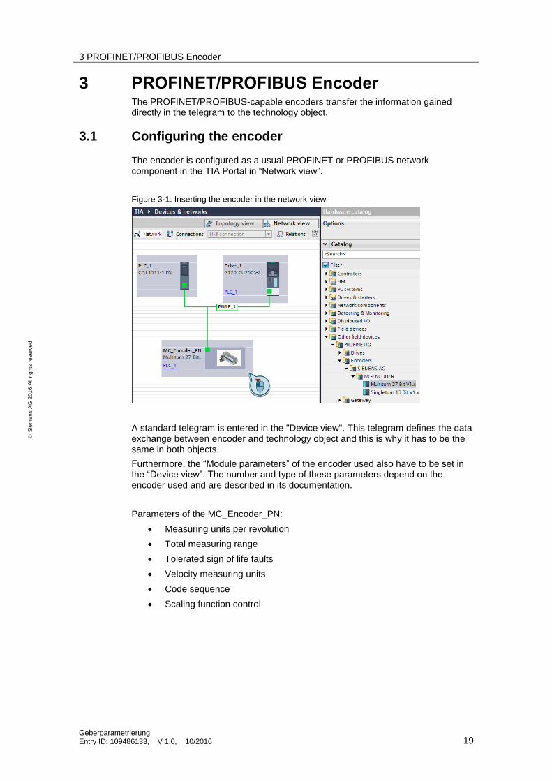
3.1 Configuring the encoder
The encoder is configured as a usual PROFINET or PROFIBUS network component in the TIA Portal in “Network view”.
Figure 3-1: Inserting the encoder in the network view
A standard telegram is entered in the "Device view". This telegram defines the data exchange between encoder and technology object and this is why it has to be the same in both objects.
Furthermore, the “Module parameters” of the encoder used also have to be set in the “Device view”. The number and type of these parameters depend on the encoder used and are described in its documentation.
Parameters of the MC_Encoder_PN:
Measuring units per revolution
Total measuring range
Tolerated sign of life faults
Velocity measuring units
Code sequence
Scaling function control
3 PROFINET/PROFIBUS Encoder
Geberparametrierung Entry ID: 109486133, V 1.0, 10/2016 20
S
iem
en
s A
G 2
01
6 A
ll ri
gh
ts r
ese
rve
d
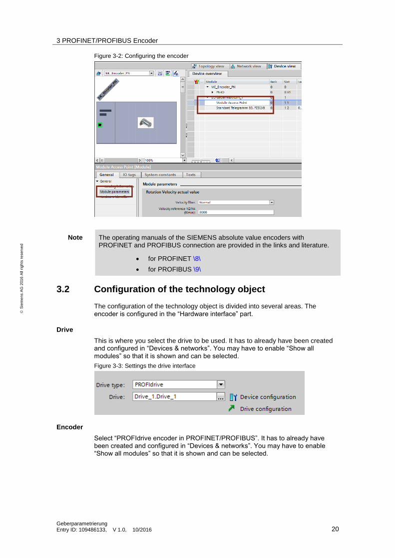
Figure 3-2: Configuring the encoder
Note The operating manuals of the SIEMENS absolute value encoders with PROFINET and PROFIBUS connection are provided in the links and literature.
for PROFINET \8\
for PROFIBUS \9\
3.2 Configuration of the technology object
The configuration of the technology object is divided into several areas. The encoder is configured in the “Hardware interface” part.
Drive
This is where you select the drive to be used. It has to already have been created and configured in “Devices & networks”. You may have to enable “Show all modules” so that it is shown and can be selected.
Figure 3-3: Settings the drive interface
Encoder
Select “PROFIdrive encoder in PROFINET/PROFIBUS”. It has to already have been created and configured in “Devices & networks”. You may have to enable “Show all modules” so that it is shown and can be selected.
3 PROFINET/PROFIBUS Encoder
Geberparametrierung Entry ID: 109486133, V 1.0, 10/2016 21
S
iem
en
s A
G 2
01
6 A
ll ri
gh
ts r
ese
rve
d
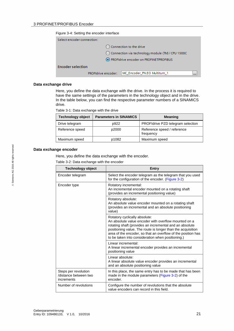
Figure 3-4: Setting the encoder interface
Data exchange drive
Here, you define the data exchange with the drive. In the process it is required to have the same settings of the parameters in the technology object and in the drive. In the table below, you can find the respective parameter numbers of a SINAMICS drive.
Table 3-1: Data exchange with the drive
Technology object Parameters in SINAMICS Meaning
Drive telegram p922 PROFIdrive PZD telegram selection
Reference speed p2000 Reference speed / reference frequency
Maximum speed p1082 Maximum speed
Data exchange encoder
Here, you define the data exchange with the encoder.
Table 3-2: Data exchange with the encoder
Technology object Entry
Encoder telegram Select the encoder telegram as the telegram that you used for the configuration of the encoder. (Figure 3-2)
Encoder type Rotatory incremental: An incremental encoder mounted on a rotating shaft (provides an incremental positioning value)
Rotatory absolute: An absolute value encoder mounted on a rotating shaft (provides an incremental and an absolute positioning value)
Rotatory cyclically absolute: An absolute value encoder with overflow mounted on a rotating shaft (provides an incremental and an absolute positioning value. The route is longer than the acquisition area of the encoder, so that an overflow of the position has to be taken into consideration when positioning.)
Linear incremental: A linear incremental encoder provides an incremental positioning value
Linear absolute: A linear absolute value encoder provides an incremental and an absolute positioning value
Steps per revolution /distance between two increments
In this place, the same entry has to be made that has been made in the module parameters (Figure 3-2) of the encoder.
Number of revolutions Configure the number of revolutions that the absolute value encoders can record in this field.
3 PROFINET/PROFIBUS Encoder
Geberparametrierung Entry ID: 109486133, V 1.0, 10/2016 22
S
iem
en
s A
G 2
01
6 A
ll ri
gh
ts r
ese
rve
d
Technology object Entry
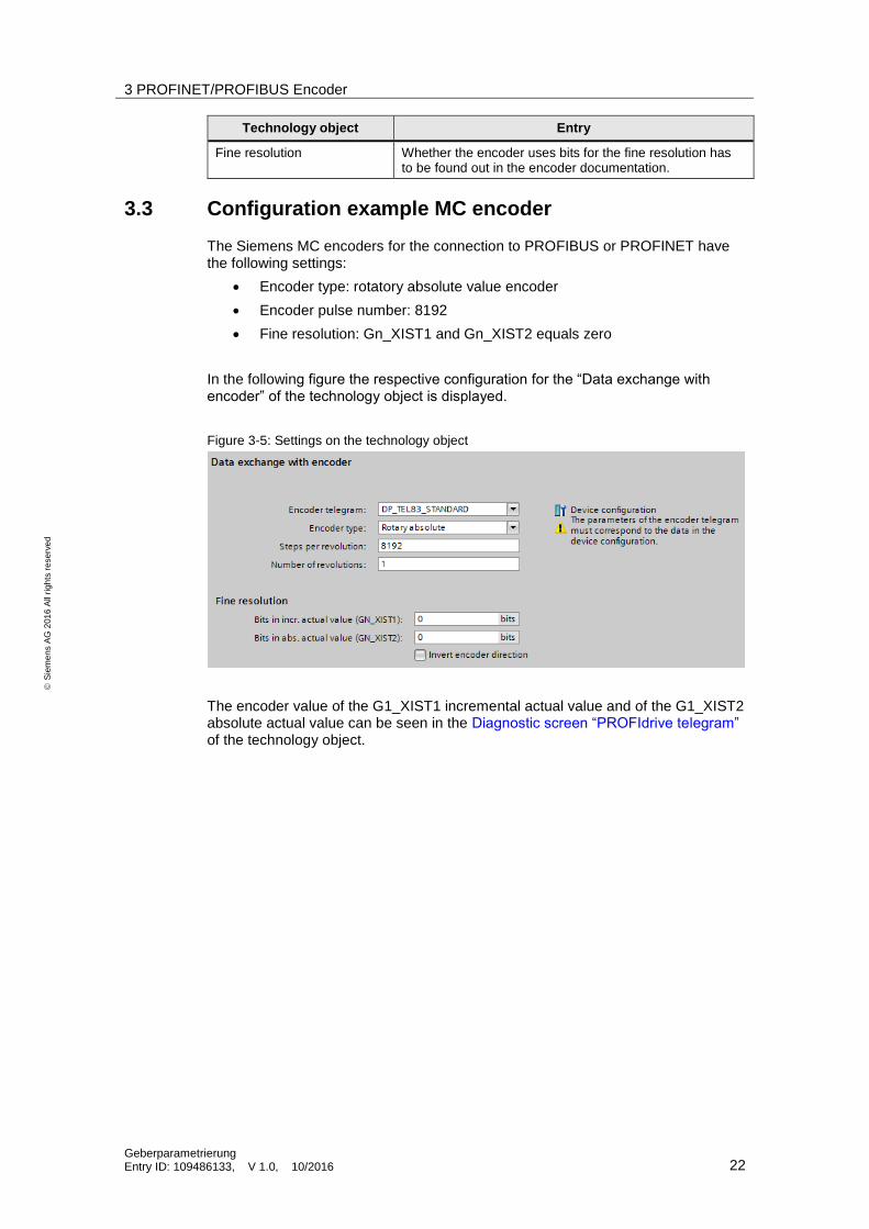
Fine resolution Whether the encoder uses bits for the fine resolution has to be found out in the encoder documentation.
3.3 Configuration example MC encoder
The Siemens MC encoders for the connection to PROFIBUS or PROFINET have the following settings:
Encoder type: rotatory absolute value encoder
Encoder pulse number: 8192
Fine resolution: Gn_XIST1 and Gn_XIST2 equals zero
In the following figure the respective configuration for the “Data exchange with encoder” of the technology object is displayed.
Figure 3-5: Settings on the technology object
The encoder value of the G1_XIST1 incremental actual value and of the G1_XIST2 absolute actual value can be seen in the Diagnostic screen “PROFIdrive telegram” of the technology object.
4 Technical Information
Geberparametrierung Entry ID: 109486133, V 1.0, 10/2016 23
S
iem
en
s A
G 2
01
6 A
ll ri
gh
ts r
ese
rve
d
4 Technical Information
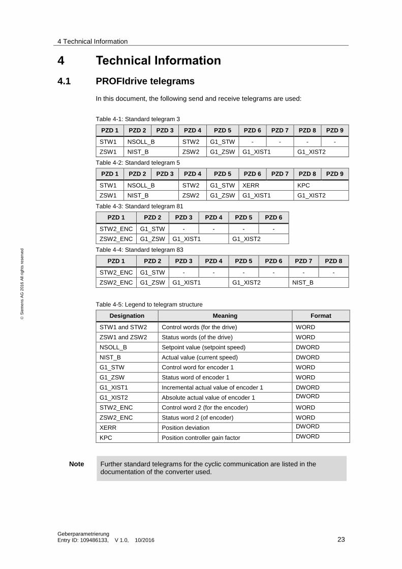
4.1 PROFIdrive telegrams
In this document, the following send and receive telegrams are used:
Table 4-1: Standard telegram 3
PZD 1 PZD 2 PZD 3 PZD 4 PZD 5 PZD 6 PZD 7 PZD 8 PZD 9
STW1 NSOLL_B STW2 G1_STW - - - -
ZSW1 NIST_B ZSW2 G1_ZSW G1_XIST1 G1_XIST2
Table 4-2: Standard telegram 5
PZD 1 PZD 2 PZD 3 PZD 4 PZD 5 PZD 6 PZD 7 PZD 8 PZD 9
STW1 NSOLL_B STW2 G1_STW XERR KPC
ZSW1 NIST_B ZSW2 G1_ZSW G1_XIST1 G1_XIST2
Table 4-3: Standard telegram 81
PZD 1 PZD 2 PZD 3 PZD 4 PZD 5 PZD 6
STW2_ENC G1_STW - - - -
ZSW2_ENC G1_ZSW G1_XIST1 G1_XIST2
Table 4-4: Standard telegram 83
PZD 1 PZD 2 PZD 3 PZD 4 PZD 5 PZD 6 PZD 7 PZD 8
STW2_ENC G1_STW - - - - - -
ZSW2_ENC G1_ZSW G1_XIST1 G1_XIST2 NIST_B
Table 4-5: Legend to telegram structure
Designation Meaning Format
STW1 and STW2 Control words (for the drive) WORD
ZSW1 and ZSW2 Status words (of the drive) WORD
NSOLL_B Setpoint value (setpoint speed) DWORD
NIST_B Actual value (current speed) DWORD
G1_STW Control word for encoder 1 WORD
G1_ZSW Status word of encoder 1 WORD
G1_XIST1 Incremental actual value of encoder 1 DWORD
G1_XIST2 Absolute actual value of encoder 1 DWORD
STW2_ENC Control word 2 (for the encoder) WORD
ZSW2_ENC Status word 2 (of encoder) WORD
XERR Position deviation DWORD
KPC Position controller gain factor DWORD
Note Further standard telegrams for the cyclic communication are listed in the documentation of the converter used.
4 Technical Information
Geberparametrierung Entry ID: 109486133, V 1.0, 10/2016 24
S
iem
en
s A
G 2
01
6 A
ll ri
gh
ts r
ese
rve
d
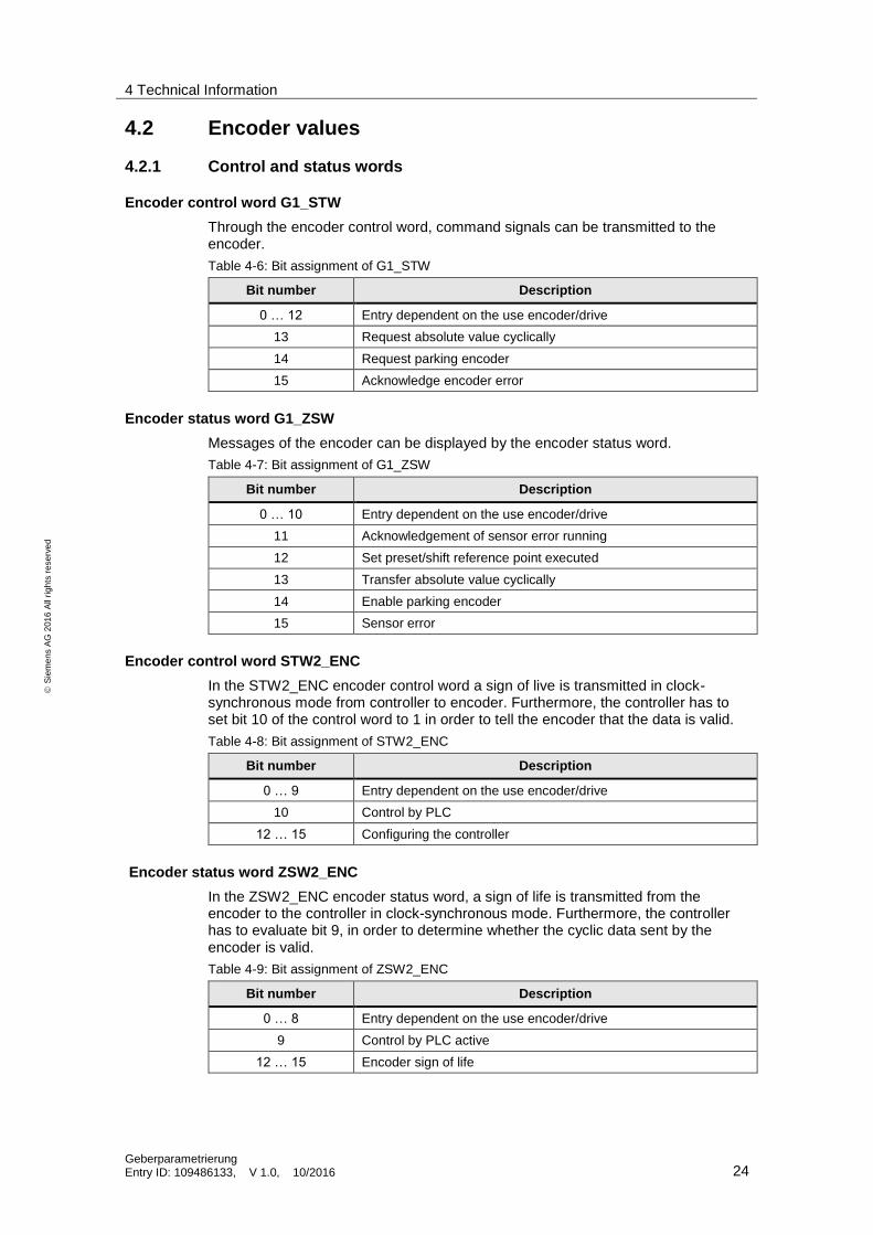
4.2 Encoder values
4.2.1 Control and status words
Encoder control word G1_STW
Through the encoder control word, command signals can be transmitted to the encoder.
Table 4-6: Bit assignment of G1_STW
Bit number Description
0 … 12 Entry dependent on the use encoder/drive
13 Request absolute value cyclically
14 Request parking encoder
15 Acknowledge encoder error
Encoder status word G1_ZSW
Messages of the encoder can be displayed by the encoder status word.
Table 4-7: Bit assignment of G1_ZSW
Bit number Description
0 … 10 Entry dependent on the use encoder/drive
11 Acknowledgement of sensor error running
12 Set preset/shift reference point executed
13 Transfer absolute value cyclically
14 Enable parking encoder
15 Sensor error
Encoder control word STW2_ENC
In the STW2_ENC encoder control word a sign of live is transmitted in clock-synchronous mode from controller to encoder. Furthermore, the controller has to set bit 10 of the control word to 1 in order to tell the encoder that the data is valid.
Table 4-8: Bit assignment of STW2_ENC
Bit number Description
0 … 9 Entry dependent on the use encoder/drive
10 Control by PLC
12 … 15 Configuring the controller
Encoder status word ZSW2_ENC
In the ZSW2_ENC encoder status word, a sign of life is transmitted from the encoder to the controller in clock-synchronous mode. Furthermore, the controller has to evaluate bit 9, in order to determine whether the cyclic data sent by the encoder is valid.
Table 4-9: Bit assignment of ZSW2_ENC
Bit number Description
0 … 8 Entry dependent on the use encoder/drive
9 Control by PLC active
12 … 15 Encoder sign of life
4 Technical Information
Geberparametrierung Entry ID: 109486133, V 1.0, 10/2016 25
S
iem
en
s A
G 2
01
6 A
ll ri
gh
ts r
ese
rve
d
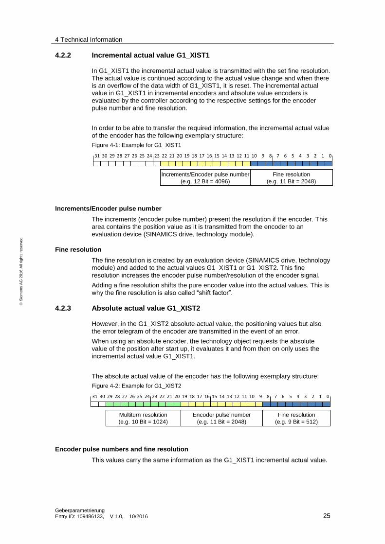
4.2.2 Incremental actual value G1_XIST1
In G1_XIST1 the incremental actual value is transmitted with the set fine resolution. The actual value is continued according to the actual value change and when there is an overflow of the data width of G1_XIST1, it is reset. The incremental actual value in G1_XIST1 in incremental encoders and absolute value encoders is evaluated by the controller according to the respective settings for the encoder pulse number and fine resolution.
In order to be able to transfer the required information, the incremental actual value of the encoder has the following exemplary structure:
Figure 4-1: Example for G1_XIST1
31 30 29 28 27 26 25 24 23 22 21 20 19 18 17 16 15 14 13 12 11 10 9 8 7 6 5 4 3 2 1 0
Fine resolution
(e.g. 11 Bit = 2048)
Increments/Encoder pulse number
(e.g. 12 Bit = 4096)
Increments/Encoder pulse number
The increments (encoder pulse number) present the resolution if the encoder. This area contains the position value as it is transmitted from the encoder to an evaluation device (SINAMICS drive, technology module).
Fine resolution
The fine resolution is created by an evaluation device (SINAMICS drive, technology module) and added to the actual values G1_XIST1 or G1_XIST2. This fine resolution increases the encoder pulse number/resolution of the encoder signal.
Adding a fine resolution shifts the pure encoder value into the actual values. This is why the fine resolution is also called “shift factor”.
4.2.3 Absolute actual value G1_XIST2
However, in the G1_XIST2 absolute actual value, the positioning values but also the error telegram of the encoder are transmitted in the event of an error.
When using an absolute encoder, the technology object requests the absolute value of the position after start up, it evaluates it and from then on only uses the incremental actual value G1_XIST1.
The absolute actual value of the encoder has the following exemplary structure:
Figure 4-2: Example for G1_XIST2
31 30 29 28 27 26 25 24 23 22 21 20 19 18 17 16 15 14 13 12 11 10 9 8 7 6 5 4 3 2 1 0
Fine resolution
(e.g. 9 Bit = 512)
Encoder pulse number
(e.g. 11 Bit = 2048)
Multiturn resolution
(e.g. 10 Bit = 1024)
Encoder pulse numbers and fine resolution
This values carry the same information as the G1_XIST1 incremental actual value.
4 Technical Information
Geberparametrierung Entry ID: 109486133, V 1.0, 10/2016 26
S
iem
en
s A
G 2
01
6 A
ll ri
gh
ts r
ese
rve
d
Multi-turn resolution
The multi-turn resolution represents the counting stored in the encoder for the full revolutions of the encoder. The technology object then calculates the absolute position value of the axis from the encoder pulse number and the multi-turn resolution.
Note Information on the structure and orientation of the actual values can be found in the documentation of the encoder used.
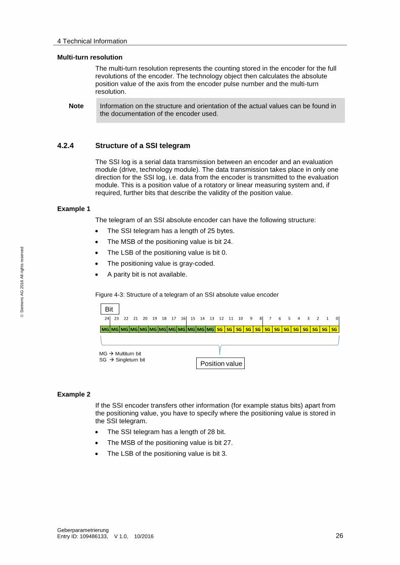
4.2.4 Structure of a SSI telegram
The SSI log is a serial data transmission between an encoder and an evaluation module (drive, technology module). The data transmission takes place in only one direction for the SSI log, i.e. data from the encoder is transmitted to the evaluation module. This is a position value of a rotatory or linear measuring system and, if required, further bits that describe the validity of the position value.
Example 1
The telegram of an SSI absolute encoder can have the following structure:
The SSI telegram has a length of 25 bytes.
The MSB of the positioning value is bit 24.
The LSB of the positioning value is bit 0.
The positioning value is gray-coded.
A parity bit is not available.
Figure 4-3: Structure of a telegram of an SSI absolute value encoder
MG
24
MG MG MG MG MG MG MG MG
23 22 21 20 19 18 17 16
MG MG MG SG SG SG SG SG
15 14 13 12 11 10 9 8
SG SG SG SG SG SG SG SG
7 6 5 4 3 2 1 0
Bit
Position value
MG Multiturn bit
SG Singleturn bit
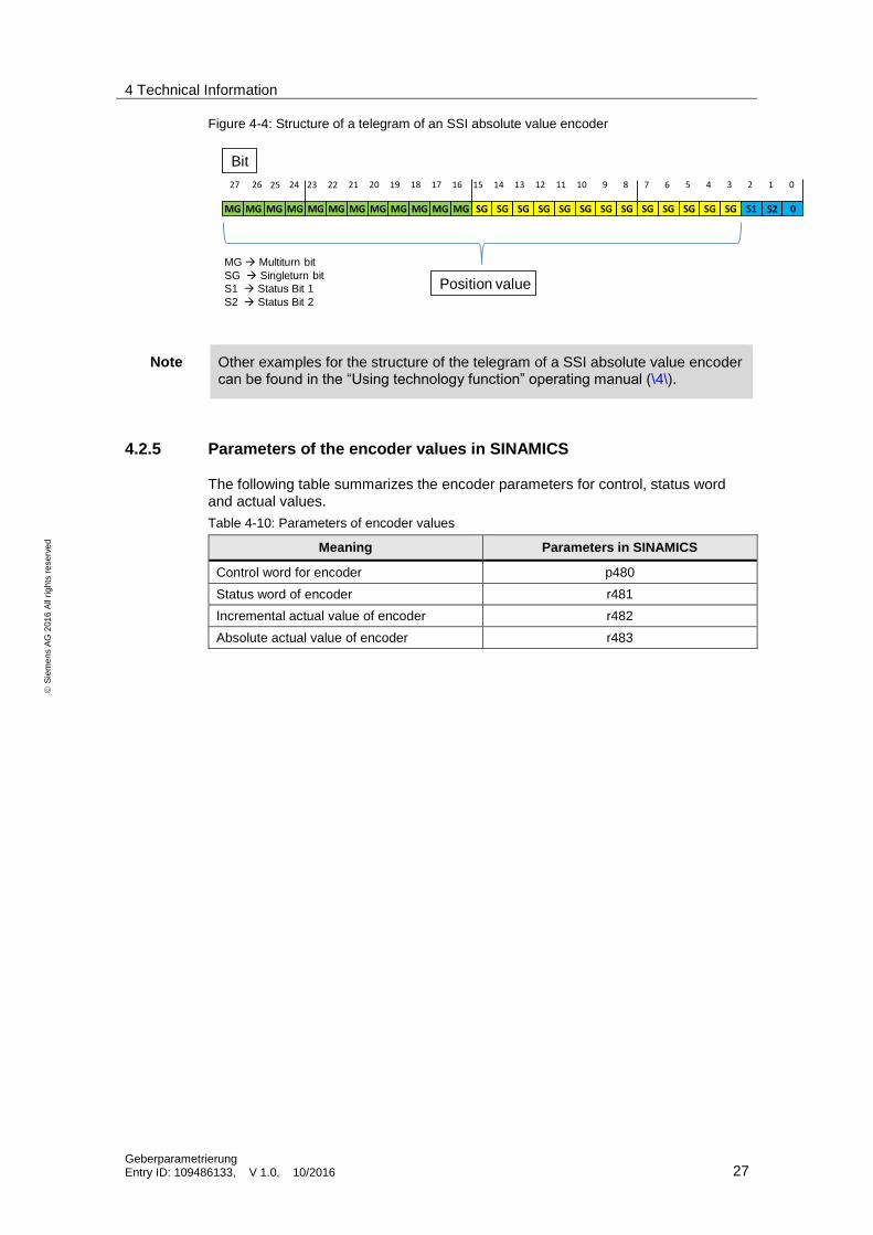
Example 2
If the SSI encoder transfers other information (for example status bits) apart from the positioning value, you have to specify where the positioning value is stored in the SSI telegram.
The SSI telegram has a length of 28 bit.
The MSB of the positioning value is bit 27.
The LSB of the positioning value is bit 3.
4 Technical Information
Geberparametrierung Entry ID: 109486133, V 1.0, 10/2016 27
S
iem
en
s A
G 2
01
6 A
ll ri
gh
ts r
ese
rve
d
Figure 4-4: Structure of a telegram of an SSI absolute value encoder
MG
24
MG MG MG MG MG MG MG MG
23 22 21 20 19 18 17 16
MG MG MG SG SG SG SG SG
15 14 13 12 11 10 9 8
SG SG SG SG SG SG SG SG
7 6 5 4 3 2 1 0
Bit
Position value
MG Multiturn bit
SG Singleturn bit
S1 Status Bit 1
S2 Status Bit 2
S1 S2 0
252627
Note Other examples for the structure of the telegram of a SSI absolute value encoder can be found in the “Using technology function” operating manual (\4\).
4.2.5 Parameters of the encoder values in SINAMICS
The following table summarizes the encoder parameters for control, status word and actual values.
Table 4-10: Parameters of encoder values
Meaning Parameters in SINAMICS
Control word for encoder p480
Status word of encoder r481
Incremental actual value of encoder r482
Absolute actual value of encoder r483
5 Links & Literature
Geberparametrierung Entry ID: 109486133, V 1.0, 10/2016 28
S
iem
en
s A
G 2
01
6 A
ll ri
gh
ts r
ese
rve
d
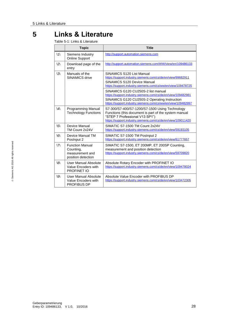
5 Links & Literature Table 5-1: Links & Literature
Topic Title
\1\ Siemens Industry Online Support
http://support.automation.siemens.com
\2\ Download page of the entry
http://support.automation.siemens.com/WW/view/en/109486133
\3\ Manuals of the SINAMICS drive
SINAMICS S120 List Manual https://support.industry.siemens.com/cs/de/en/view/99682911
SINAMICS S120 Device Manual https://support.industry.siemens.com/cs/ww/en/view/109478725
SINAMICS G120 CU250S-2 list manual https://support.industry.siemens.com/cs/de/en/view/109482981
SINAMICS G120 CU250S-2 Operating Instruction https://support.industry.siemens.com/cs/ww/en/view/109482997
\4\ Programming Manual Technology Functions
S7-300/S7-400/S7-1200/S7-1500 Using Technology Functions (this document is part of the system manual “STEP 7 Professional V13 SP1”) https://support.industry.siemens.com/cs/de/en/view/109011420
\5\ Device Manual TM Count 2x24V
SIMATIC S7-1500 TM Count 2x24V https://support.industry.siemens.com/cs/de/en/view/59193105
\6\ Device Manual TM PosInput 2
SIMATIC S7-1500 TM PosInput 2 https://support.industry.siemens.com/cs/de/en/view/61777657
\7\ Function Manual Counting, measurement and position detection
SIMATIC S7-1500, ET 200MP, ET 200SP Counting, measurement and position detection https://support.industry.siemens.com/cs/de/en/view/59709820
\8\ User Manual Absolute Value Encoders with PROFINET IO
Absolute Rotary Encoder with PROFINET IO https://support.industry.siemens.com/cs/de/en/view/109478024
\9\ User Manual Absolute Value Encoders with PROFIBUS DP
Absolute Value Encoder with PROFIBUS DP https://support.industry.siemens.com/cs/de/en/view/103472305