Embed Size (px)
Citation preview
ExternalPol meric
Pioeline oatingailureModes
SANKARAPAPAVINASAM,MICHAEL ATIARD, AND R. WINSTON REvIE,
CANMET Materials TechnologyLaboratory
Pipelinecoatingisa majordefenseagainstcorrosion.Cathodicprotectionprovidesprotection
atcoatingholidays.Anychangeinthechemical.physical.orelectrochemicalpropertiesofanexternalpipelinecoatingcanbeconsideredasafailure.Somefailuresarecatastrophic.whereasothershavelittleornoeffectonthecoatingperformance.Theeightmostcommonfailuremodesofexternalpolymericpipelinecoatingsareassessedinthisarticle.
s long as pipeline coatingsare intact and completelyisolate the pipeline from theenvironment, corrosionshould not occur. But over
the years, coatings undergohanges that affect their
ability to isolate the pipeline from theenvironment. Generally, any changes inthe properties of a coating are consideredas a coating failure. The degree of influ-ence of the changes on pipeline integrityvaries, depending on the extent and thenature of changes. The predominant fail-ure modes are discussed in this article.
ModeofFailureAIR PERMEATION
Polymeric pipeline coatings are perme-able because of the presence of pores at themolecular level. Gas can permeate through
28 MATERIALSPERFORMANCEOctober 2006
the pores. When gases permeate a coatingthat is well bonded to steel, the pressurewithin the coating increases. At high levelsof permeation, the build-up of pressure maybe reduced by the liberation of gases, caus-ing disbondment of the coating. At lowlevels of permeation, the state of equilib-rium is reached without any chemical orphysicalchanges to the coating.I
WATER PERMEATION
In addition to gases, water and salts canalso penetrate the coating. Permeation isfurther facilitated by osmosis and electro-osmosis. When a semipermeable mem-brane (e.g., pipeline coating) separates asolution of different concentrations, the
water permeates from the concentratedsolution side to the dilute solUtion side sothat the concentrations at both sides of the
membrane become the same. This processis called osmosis. The presence of salts onthe contaminated steel surface results in the
development of the osmosis process. Ifosmosis is facilitated by the electrical cur-rent flow caused by the application of ca-thodic protection (CP), it is called electro-osmosis.2-4
LOSS OF ADHESION
Adhesion is a measure of the degree ofattachment between the coating and thepipeline steel with which it is in contact.The adhesion is a force that keeps the coat-ing on the steel surface.5 Adhesion may becaused by chemical, physical, and me-chanical interactions. When these interac-
tions are diminished, the coating loses itsadhesion.
LOSS OF COHESION
The cohesive strength is the bondingwithin the coating itself that holds the coat-
ing together as an entity. A coating withgreat cohesion will break the adhesive bondwith the surface and then peel from thesurface to form a free-standing coating (Fig-ure 1). On the other hand, if the cohesive
strength is less than the adhesive strength,the coating will break within itself, leavingpart of the coating on the surface and parrof it off the surface (Figure 2).6 Becausethepipe surface is protected by the remainder
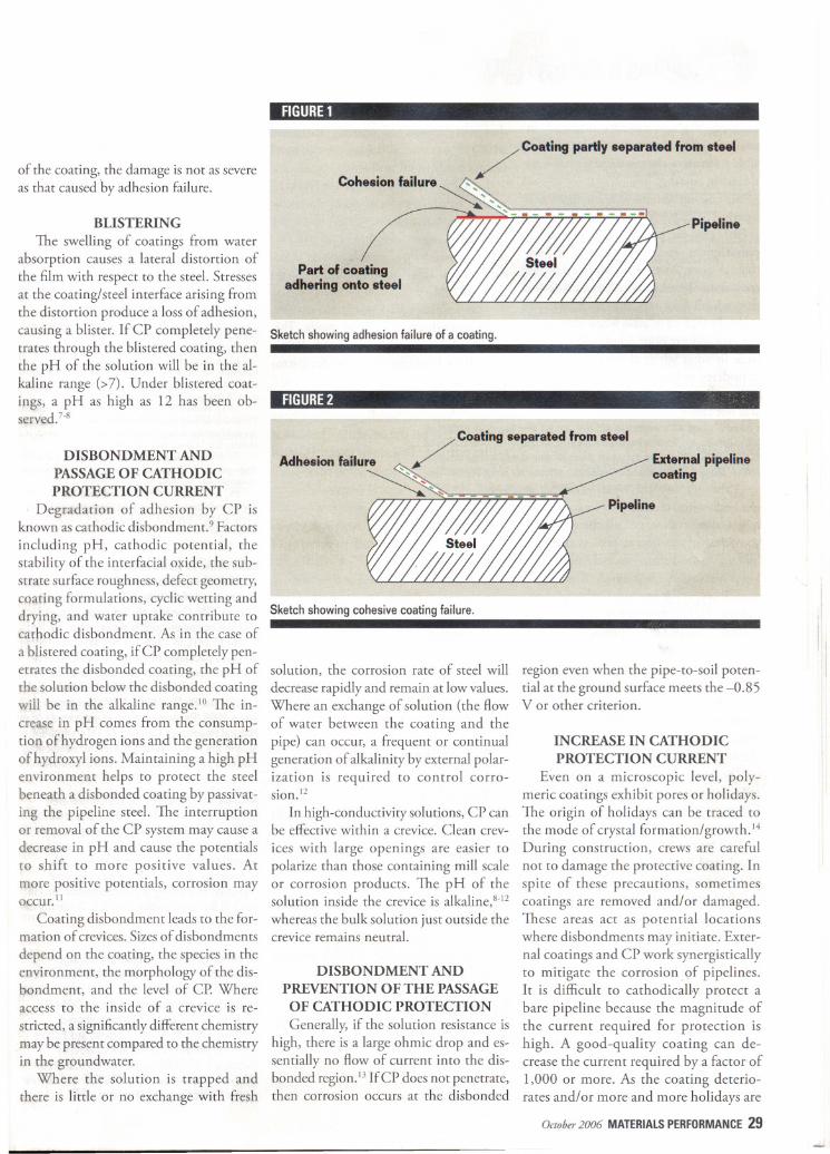
of the coating, the damage is not as severeas that caused hy adhesion failure.
BLISTERING
The swelling of coatings from waterabsorption causes a lateral distortion ofthe film with respect to the steel.Stressesat the coating/steel interface arising fromthe distortion produce a lossof adhesion,causing a blister. If CP completely pene-trates through the blistered coating, thenthe pH of the solution will be in the al-kaline range (>7). Under blistered coat-ings, a pH as high as 12 has been ob-served.7-s
DISBONDMENT ANDPASSAGE OF CATHODICPROTECTION CURRENT
Degradation of adhesion by CP isknown as cathodic disbondment.9 Factors
including pH, cathodic potential, thestability of the interfacial oJ{ide, the sub-strate surface roughness, defect geometry,coating formulations, cyclic wetting anddrying, and water uptake contribute tocat/lOdic disbondment. As in the case of
a blistered coating, if CP completely pen-etrates the disbonded coating, the pH ofthe solution below the disbonded coatingwill be in the alkaline range.IO The in-crease in pH comes from the consump-tion of hydrogen ions and the generationof hydroxyl ions. Maintaining a high pHenvironment helps to protect the steelbeneath a disbonded coating by passivat-ing the pipeline steel. The interruptionor removal of the CP system may cause adecrease in pH and cause the potentialsto shift to more positive values. Atmore positive potentials, corrosion mayoccur. II
Coating disbondment leads to the for-mation of crevices. Sizes of disbondments
depend on the coating, the species in theenvironment, the morphology of the dis-bondment, and the level of CP. Whereaccess to the inside of a crevice is re-
stricted, a significantly different chemistrymay be present compared to the chemistryin the groundwater.
Where the solution is trapped andthere is little or no exchange with fresh
FIGURE1
/' Coating partly separated from steelCohesion failure ~"
~ ""''.., .-~ , ,.-Pipeline
Part of coatingadhering onto steel
Sketchshowingadhesionfailure of a coating.
FIGURE2
Sketchshowing cohesivecoatingfailure.
solution, the corrosion rate of steel will
decrease rapidly and remain at low values.Where an exchange of solution (the flowof water between the coating and thepipe) can occur, a frequent or continualgeneration of alkalinity by external polar-ization is required to control corro-sion.12
In high-conductivity solutions, CP canbe effective within a crevice. Clean crev-
ices with large openings are easier topolarize than those containing mill scaleor corrosion products. The pH of thesolution inside the crevice is alkaline,s-12
whereas the bulk solution just outside thecrevice remains neutral.
DISBONDMENT ANDPREVENTION OF THE PASSAGEOF CATHODIC PROTECTION
Generally, if the solution resistance is
high, there is a large ohmic drop and es-sentially no flow of current into the dis-bonded region. 13If CP does not penetrate,then corrosion occurs at the disbonded
region even when the pipe-to-soil poten-tial at the ground surface meets the -0.85V or other criterion.
INCREASE IN CATHODICPROTECTION CURRENT
Even on a microscopic level, poly-meric coatings exhibit pores or holidays.The origin of holidays can be traced tothe mode of crystal formation/growth.14During construction, crews are carefulnot to damage the protective coating. Inspite of these precautions, sometimescoatings are removed and/or damaged.These areas act as potential locationswhere disbondments may initiate. Exter-nal coatings and CP work synergisticallyto mitigate the corrosion of pipelines.It is difficult to cathodicaUy protect abare pipeline because the magnitude ofthe current required for protection ishigh. A good-quality coating can de-crease the current required by a factor of1,000 or more. As the coating deterio-rates and/or more and more holidays are
Octob" 2006 MATERIALSPERFORMANCE29
lo_us aLinings
formed, the CP current demand in-
creases, until it is economically not fea-sible to protect the pipeline with a dete-riorating coating.
Six coating systems were evaluated overa period of25 years: fusion-bonded epoxy(FBE), coal-tar enamel, asphalt enamel,polyethylene tape, asphalt mastic, and ure-thane. 15Several locations exhibited pittingcorrosion. These locations were distributed
through all four coating types and weregenerally located in areas where the coatingconditions were poor. Many of the defectswere in areas where the CP was initiallyconsidered to be adequate, indicating that,where coatings were in poor condition, CPwas not completely effective.
RankingofCoatingFailureModes
Although any chemical, physical, orelectrochemical changes may be consideredas a coating failure, not all changes affectthe ability of coatings to protect the pipe-line. In an ideal situation, polymeric coat-ing protects the pipeline and, when it fails,the CP acts as the backup. Only after bothdefense mechanisms failwould the pipelinebecome susceptible to corrosion.
The worst-case scenario of coating fail-ure is the one in which the coating nolonger protects the pipeline, and, in addi-tion, the coating prevents the CP fromprotecting the pipeline. This type of failuremode is primary in terms of the impact ofthe failure on the protection of the pipe.
The presence of holidays is the secondmost common cause offailure because the
CP current increases as the holiday sizeand number increase. The alkaline pHcreated by the CP can easily become dif-fused, and hence, the CP should be ap-plied continuously.
The formation of disbondment behind
a coating that passes CP presents the thirdranking. In this case the coating has failed,but CP can act as the backup. Because ofthe diffusion limitation of the hydroxide(OH-) ions, the amount of CP requiredis smaller.
The formation of blisters is the fourth-
ranked cause of coating failure. This fail-ure is associated with the penetration ofwater, so that CP can prevent corrosionat this location. This case is better than
30 MATERIALSPERFORMANCEOctober 2006
that with disbonded coating protectedwith CP because CP reaches the steel
surface readily and uniformly.Loss of adhesion makes the coating
unable to perform its primary function(Le., to cover the steel surface). This is thefifth-ranked mode of failure. Loss of cohe-
sion is the sixth because at least part of thecoating still covers (and hence protects)the steel surface.
Water permeation through the coatingis the seventh-ranked failure mode. Thismode of failure establishes electrochemi-
cal cells, facilitating conditions for corro-sion to occur.
The permeation of gases may breakcertain chemical bonds, but may havelimited effect on the overall performanceof the coating. This is the eighth-rankedfailure mode.
Summary·Any change in the chemical, physi-cal, or electrochemical properties ofthe external polymeric pipeline coat-ings can be considered as a failure.· Some failures are catastrophic,whereas others have little or no effect
on the coating performance.· The eight most common failuremodes of external polymeric pipelinecoatings are ranked in the order of theimpact of the failure on the protectionof the pipe.
AcknowledgmentsThe authors would like to acknowledge
the helpful discussions and financial suppottfrom the Canadian Federal Government's
Program of Energy R&D (PERD) and itsmembers (Alberta Energy Corporation[AEC], Enbridge, KOGAS, Reilly Indus-tries, Shaw Pipe Coating, Specialty PolymerCoatings [SPC], TransCanada Pipeline[TCPL] and 3M) of the CANMET/NRC/
Industry Consortium on External PipelineCoatings for Prevention of Corrosion andStress-Corrosion Cracking.
ReferencesI. D.E Siddal. "Permeability and Corrosion in PrOlecrive
Coatings; Corrosion 2. 6 (1946): p. 78.2. E Bellucci. L. Nicodemo. "Warer Transport in Organic
Coatings; Corrosion 49. 3 (1993): p. 235.3. NACE Task Group T-6B-B. "Amine-Cured Epoxy
Resin Coatings for Resisrance ro Atmospheric Corrosion;
MP 9.5 (1970): p. 37.
4. D. Gervasio. I. Song. B. Trautman. J.H. Payer. "Fun-damental Research on Disbonding of Pipeline Coatings; GasResearch Institute Report GRI-93/0265/GTI211O. 1993.
5. "Line Pipe Coating Analysis Volume 2: Topical Re-port on Adhesion; American Gas Association. November1979. p. 38.
6. e.G. Munger. "Surfaces. Adhesion. Coatings; MP5. 7 (1983): p. 33.
7. W. Schneider. "Ambient Temperarure Curing Water-borne Epoxy Systems,"MP 30. I (1991): p. 28.
8. G.R. Ruschau. J.A. Beavers. "Performance of Blistered
FBE-Coated Pipe; PR-186-981 O. December 2000.9. J.H. Payer. B. Trautman. D. Gervasio. "Chemical and
Electrochemical Processes ofCarhodic Disbanding of PipelineCoatings; CORROSION/93. paper no. 579 (Housron. TX:NACE International. 1993).
10. R.N. Parkins. A.J. Markworrh.J.H. Holbrook. R.R.
Fessler. Cottosion 41. 7 (1985): p. 389.II. B.W. Cherry. A.N. Gould. MP 6. 8 (1990): p. 22.12. K. Fink, J.H. Payer. R. Savinell. "Mitigation of
Corrosion by Modification of the Environmenr Beneath
Disbanded Coatings on Pipelines; CORROSION/93. paperno. 578 (Houston, TIC: NACE, 1993).
13. J.J. Perdomo. I. Song, "Chemical and EIecrrochemicalConditions on Steel under Disbonded Coatings: The Effect of
Applied Potential. Solution Resistivity. Crevice Thickness. andHoliday Size; Corros. ScL 42 (2000): p. 1.389.
14. S. Papavinasam, "Permeability and EIectrocatalyticProperries of Film Prepared by Electropolymerisation of ffi-Aminophenol; Synrhetic Metals 58 (1993): p. 173.
15. J.L. Banach. "Pipeline Coatings-Evaluation.Repair, and Impact on Corrosion Protection Design and
Cost; CORROSION/87. paper no. 29 (Houston, TX:NACE.1987).
SANKARAPAPAVINASAMis a research sci-
entist and project leader at CANMETMaterialsTechnology laboratory (MTU, 568 Booth St.,Ottawa, ON, Canada. He has been involved in
pipeline corrosion control issues since joiningCANMET MTL in 1994. He has developed threesoftware packages for prediction and controlof internal and external corrosion of oil and
gas pipelines. He has an M.Sc. <1984>,M.Phil<1985>,and Ph.D. <19901.A NACE member
since 1996, Papavinasam received awards fromNatural Resources Canada,ASTMInternation-al, and the NACENorthern Area for developingmethods and techniques to control corrosion.
MICHAELATTARDis a corrosion research
technologist at CANMETMTL. He is involved
in exterior polymeric coatings performance,inhibitor behavior, and corrosion prevention,as well as analysis method evaluation. He
is currently working in the area of internalcorrosion monitoring and characterization. He
has a B.Sc. in chemistry from the University ofWestern Ontario.
R. WINSTON REVIEis programmanager-infrastructure reliability at CANMETMTL.Hehas been involved in research and developmenton pipeline corrosion since joining CANMETin 1978. He and H.H. Uhlig co-authoredCo"osion and Co"osion Control, 3rd Edition,
and he is the editor of Uhlig's Co"osionHandbook, 2nd Edition. He has a Ph.D. from
MIT, is a 33.year member of NACE, and serveson the NACEBoardof Directors. IVP