Embed Size (px)
Citation preview
37Cellular Polymers, Vol. 20, No. 1, 2001
Polyethylene Casing as Diffusion Barrier for Polyurethane Insulated District Heating Pipes
The Polyethylene Casing as DiffusionBarrier for Polyurethane Insulated District
Heating Pipes
Maria Olsson and Ulf JarfeltDepartment of Building Physics
Morgan Fröling and Olle RamnäsDepartment of Chemical Environmental Science
Chalmers University of TechnologyS – 412 96 Göteborg, Sweden
Received: 19th December 2000; Accepted: 15th February 2001
SUMMARY
Most district heating pipes are insulated with polyurethane foam in order tominimise heat losses. A high-density polyethylene (HDPE) casing protects theinsulated pipe, and its permeability properties for the polyurethane cell gases,including air, play an important role for the long-term insulating capacity.
The permeability of the HDPE casing of a district heating pipe was studied.Two methods were used to determine the permeability: I) by measuring the masstransfer through a sample, and II) by measuring the sorption and desorption ofthe gas in a sample. The experimental procedures are described. For carbondioxide a permeability coefficient of about 9·10-16 mole·m-1·s-1·Pa-1 was foundby both methods. For oxygen and nitrogen only method I was used and thepermeability coefficients found were 1.9 and 0.6·10-16 mole·m-1·s-1·Pa-1,respectively.
INTRODUCTION
District heating pipes distribute hot water to heat consumers and areinsulated with polyurethane (PUR) foam to minimise heat losses. A goodlong-term insulating capacity will result in energy savings and a subsequentlowering of the total environmental impact(1,2).
The insulating capacity of the foam decreases over time when theblowing agent diffuses out of and air diffuses into the foam(3,4). Theinsulating capacity over time is not only influenced by the diffusion of theblowing agent but also by the diffusion of air and carbon dioxide. Due tothe foaming process, carbon dioxide is always present in the PUR-foamof a district heating pipe.
A district heating pipe has an outer casing of high-density polyethylene.Together with the PUR-foam, the polyethylene casing acts as a diffusion
38 Cellular Polymers, Vol. 20, No. 1, 2001
Maria Olsson, Ulf Jarfelt, Morgan Fröling and Olle Ramnäs
barrier. For carbon dioxide, the polyethylene casing has been found to bethe main diffusion barrier(1,4). To be able to predict the long-term thermalperformance of a district heating pipe, knowledge of the diffusionproperties of gases in the casing, as well as in the foam, is needed.
Many studies on polymer permeability have been performed on films.Permeability coefficients for different gases in films of high-densitypolyethylene have been reported(5,6,7,8) and used in calculations for casingpipes, when predicting the long-term thermal performance(9,10). However,the permeability varies with different qualities of polyethylene and withdifferent drawing ratios(6). Density, crystallinity, polymer chain lengthdistribution and chain branching as well as additives are other factorsinfluencing the permeability(4,5,7). The complexity of factors affecting thepermeability gives reason for studying the specific polyethylene casingused for district heating pipes.
EXPERIMENTAL
Mass transfer of oxygen, nitrogen and carbon dioxide through polyethylenewas studied in the diffusion chamber, and sorption and desorption ofcarbon dioxide were studied in the sorption chamber.
Diffusion chamber
The diffusion chamber consists of two volumes separated from each otherby a sample of a polyethylene casing. The two volumes contain differentgases. The mass transfer through the casing can be determined by gaschromatographic analyses of the gases in the volumes.
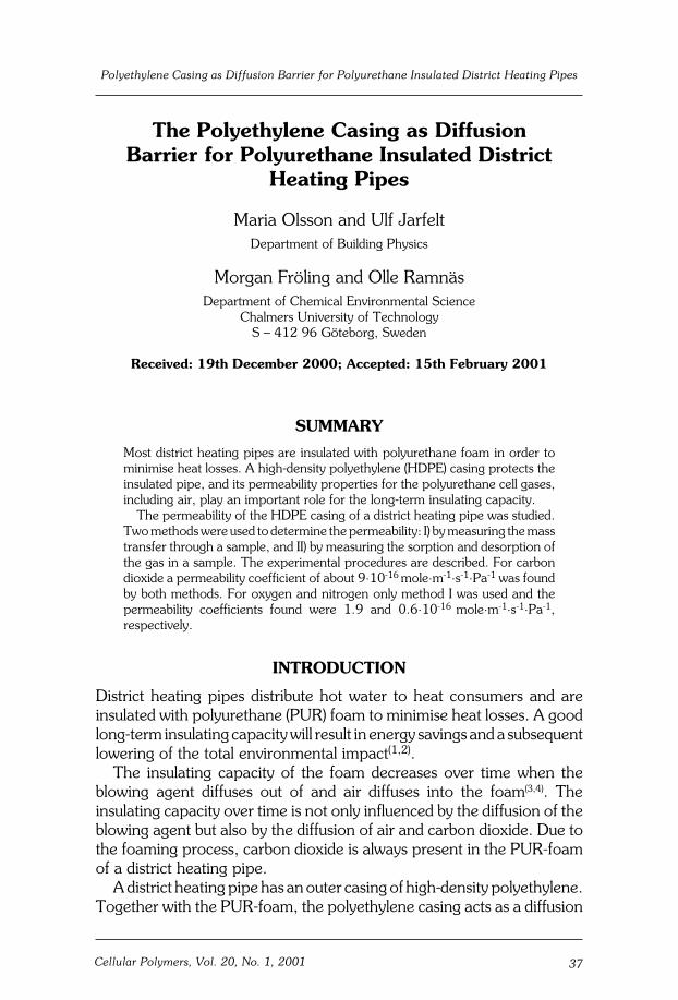
The chamber was made by welding the walls of a steel box onto a steelpipe with sealed ends. The box covers an opening cut out of the pipe,where a piece of polyethylene casing can be placed, see Figure 1. Thediameter of the steel pipe was chosen to fit a standard dimension of casingof a district heating pipe (diameter 172 mm).
The volumes were filled with gas through metal tubings, which could beclosed by ball valves.
Experimental procedure
Before application, the thickness of the casing sample was measured witha dial indicator. The sample was glued with epoxy and pressed with screwsonto the opening. Finally, a steel cover was glued with epoxy to the box.
39Cellular Polymers, Vol. 20, No. 1, 2001
Polyethylene Casing as Diffusion Barrier for Polyurethane Insulated District Heating Pipes
Figure 1 Chamber for determination of casing permeability. The volume of thepipe is 5·10-3 m3 and the volume of the box is 0.7·10-3 m3. The area of theopening, where mass transfer is possible, is 9·10-3 m2. The screws help toprovide gas tightness when the casing sample is glued onto the pipe
The size of the large volume was determined from measurements witha calliper. The size of the more irregular small volume was determined byfilling with water and weighing. The gas tightness of the volumes waschecked by applying an over-pressure of 1 bar.
In this study, the small volume was filled with carbon dioxide and thelarge volume was filled with oxygen or nitrogen. The chambers werestored at constant temperature, 23°C, during the experiments. Gassamples were taken immediately after filling and then at different times.The samples were analysed by gas chromatography.
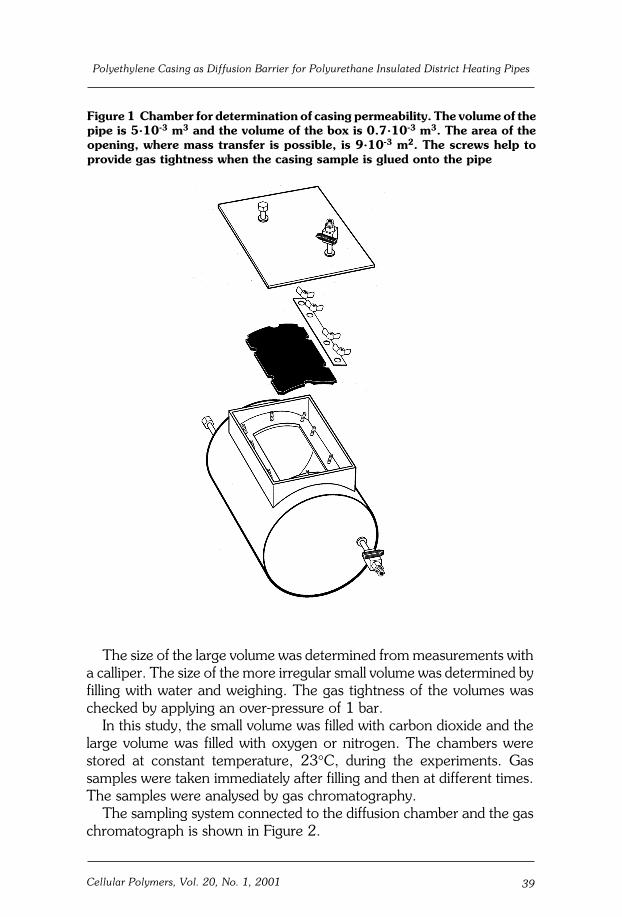
The sampling system connected to the diffusion chamber and the gaschromatograph is shown in Figure 2.
40 Cellular Polymers, Vol. 20, No. 1, 2001
Maria Olsson, Ulf Jarfelt, Morgan Fröling and Olle Ramnäs
Before sampling, the system was flushed with the filling gas of thevolume to be studied. The flushing proceeded until no other compoundsbut the flushing gas could be detected in samples taken by the gas tightsyringe (SGE, 50 ml).
When the system was clean, the syringe was filled with 30 ml of theflushing gas, and the valves into and out of the system were closed. Thevalve into the volume was opened, and the flushing gas was injected intoit. The gas was allowed to diffuse out into the volume for half a minute withthe valve closed before a sample (30 ml) was taken out with the syringe.The sample was then injected into the gas chromatographic columns viathe gas sampling valves. The reason for injecting flushing gas beforesampling was that repeated sampling should not affect the pressure insidethe volume.
In the gas chromatograph (Perkin-Elmer 3920B), the compounds wereseparated and detected. A molecular sieve column (13X, 170 cm x 1/8")was used for oxygen and nitrogen and a packed porous polymer column(HayeSep Q, 190 cm x 1/8") was used for carbon dioxide. The columnswere connected to both sides of a hot wire detector (200°C, 150 mÅ).Helium (30 ml/min) was used as a carrier gas. Calibration with pure gases
Figure 2 System for sampling and analysis of gas samples from the diffusionchamber. A gas tight syringe (A) is connected to the diffusion chamber (F) withthe casing sample (G) and to two gas sampling valves in series (B1 and B2). Gassamples are injected via the sample loops (C1 and C2, volumes around 200ml)and are separated on the gas chromatographic columns (D1 and D2) connectedto the hot wire detector (E).
CO2
N2
O2
F
G
C2
B2
C1
B1
He
He
Gas chromatograph
D1
E
D2
A
41Cellular Polymers, Vol. 20, No. 1, 2001
Polyethylene Casing as Diffusion Barrier for Polyurethane Insulated District Heating Pipes
allowed the concentration of each gas to be determined. The minimumdetectable concentration was around 0.01% (vol) for the gases studiedhere.
Sorption chamber
The sorption chamber consists of a steel autoclave. It is sealed with a steelcover with an o-ring. The chamber is filled with a gas through metaltubings, which can be closed by ball valves.
In the sorption chamber, pieces of polyethylene casing were kept in acertain gas. The sorption of gas into the polyethylene was determined byweighing, while the desorption of gas was determined by gaschromatographic analyses of the gases in the volume.
Experimental procedure
Pieces of polyethylene casing (totally about 100 g) were kept at 23°C andatmospheric pressure in the chamber filled with carbon dioxide. Thepurity of the gas was checked by gas chromatography.
During the sorption phase, an analytical balance was used to determinethe change in weight of the casing pieces at different times.
After about a week, the carbon dioxide was replaced by air. The carbondioxide dissolved in the polyethylene was then desorbed to the air. Duringthe desorption phase, the concentration of carbon dioxide in the chamberwas determined at different times by gas chromatography by the sameprocedure as described for the diffusion chamber. At the end of thedesorption phase, the carbon dioxide concentration in the chamber wasabout 1% (vol). Since the total volume of the chamber (about 1.8·10-3 m3)was known, the total amount of desorbed gas could be calculated. Theconcentration of ambient carbon dioxide, 0.04% (vol), was considered inthe calculations.
Material
The casing pipe studied was produced by a Swedish district heating pipemanufacturer from a polyethylene quality named HE2467-BL intendedfor “jacketing of district heating pipes” among other applications(11).According to the producer the density of the base resin is 943 kg·m-3, andthe density of the compound is 953 kg·m-3. Carbon black is added as fillerand the content is above 2%(11). According to the European standardEN253(12) the density of the polyethylene polymer must be at least 935kg·m-3 and the density of the polyethylene casing at least 944 kg·m-3. By

42 Cellular Polymers, Vol. 20, No. 1, 2001
Maria Olsson, Ulf Jarfelt, Morgan Fröling and Olle Ramnäs
weighing samples in air and in 2-propanol, the density of the casing usedin this study was found to be 960 kg·m-3.
When manufacturing the casing pipe, the plastic granules are meltedat 200-210°C and extruded to a pipe, which is cooled down to 20°C bydirect water spraying. During the extrusion, the casing pipe is drawnapproximately 20% to achieve the desired thickness of the pipe wall(13).
PERMEABILITY
The permeability coefficient is the material parameter used to describemass transfer rate through a material of a certain thickness.
whereJ = mass transfer rate [mole·m-2·s-1]P = permeability coefficient [mole·m-1·s-1·Pa-1]∆p = partial pressure difference [Pa]L = thickness [m]
In the diffusion-chamber experiments, the amount of gas that hadpermeated through the casing from one volume into the other wasdetermined, and the permeability coefficient was calculated as:
n = amount of gas permeated [mole]A = area [m2]t = time [s]∆p = mean partial pressure difference [Pa]
The equation assumes that the partial pressure difference is constantduring the time considered. In fact, the difference decreased by less thantwo per cent from the start to the end of the experiments.
Dilution due to the sampling procedure was considered when determiningthe amount of gas permeated.
The results from the sorption study can also be used for determinationof the permeability coefficient, under the assumption that Henry’s law,Equation (3), is valid.
J Pp
L= ⋅ ∆
Pn
A tLp
=⋅
⋅∆
P S D= ⋅
(1)
(2)
(3)
43Cellular Polymers, Vol. 20, No. 1, 2001
Polyethylene Casing as Diffusion Barrier for Polyurethane Insulated District Heating Pipes
S = solubility coefficient [mole·m-3·Pa-1]D = diffusion coefficient [m2·s-1]
The solubility coefficient is obtained from the weight of the sample atsaturation.
The diffusion coefficient is obtained from the following relationship:
c = mean concentration in sample [mole·m-3]c0 = initial concentration in sample [mole·m-3]
RESULTS
Four samples of polyethylene casing of the original thickness (around 4mm) and two samples that had been turned thinner (around 2 and 3 mm),were used in the diffusion-chamber experiments.
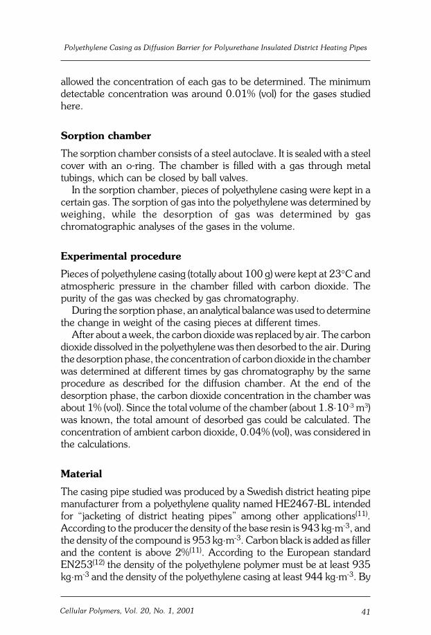
Figure 3 shows the amount of carbon dioxide, which had permeatedthrough the casing into the large volume, and the amount of either oxygenor nitrogen, which had permeated through the casing into the smallvolume when the samples of original thickness were studied.
After three weeks, the concentrations of permeated gases were 0.1-0.3% (vol).
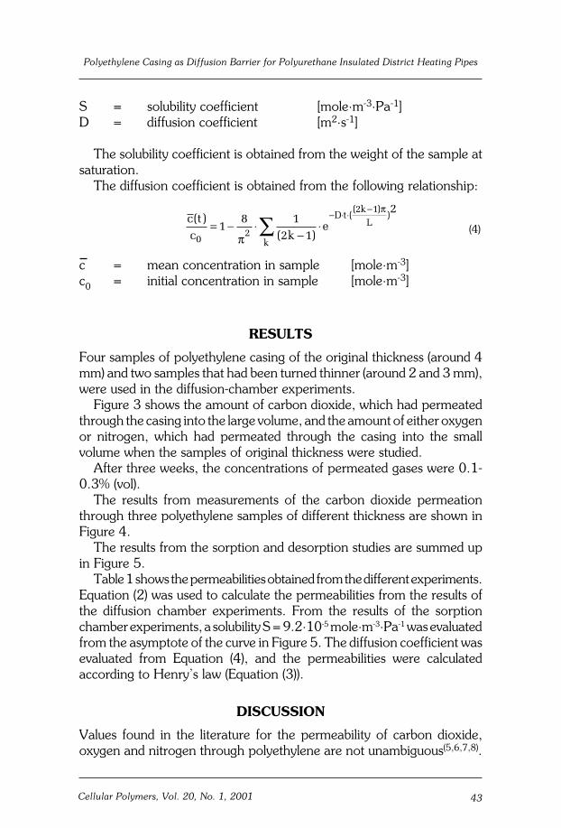
The results from measurements of the carbon dioxide permeationthrough three polyethylene samples of different thickness are shown inFigure 4.
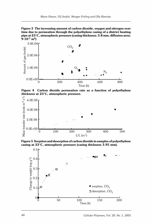
The results from the sorption and desorption studies are summed upin Figure 5.
Table 1 shows the permeabilities obtained from the different experiments.Equation (2) was used to calculate the permeabilities from the results ofthe diffusion chamber experiments. From the results of the sorptionchamber experiments, a solubility S = 9.2·10-5 mole·m-3·Pa-1 was evaluatedfrom the asymptote of the curve in Figure 5. The diffusion coefficient wasevaluated from Equation (4), and the permeabilities were calculatedaccording to Henry’s law (Equation (3)).
DISCUSSION
Values found in the literature for the permeability of carbon dioxide,oxygen and nitrogen through polyethylene are not unambiguous(5,6,7,8).
(4)c tc k
ek
D tk
L( )( )
(( )
)
02
2 1
18 1
2 1
2= − ⋅
−⋅∑
− ⋅ ⋅ −
π
π
44 Cellular Polymers, Vol. 20, No. 1, 2001
Maria Olsson, Ulf Jarfelt, Morgan Fröling and Olle Ramnäs
Figure 3 The increasing amount of carbon dioxide, oxygen and nitrogen overtime due to permeation through the polyethylene casing of a district heatingpipe at 23°C, atmospheric pressure (casing thickness: 3.8 mm, diffusion area:9·10-3 m2)
Figure 4 Carbon dioxide permeation rate as a function of polyethylenethickness at 23°C, atmospheric pressure.
3.0E-04
2.0E-04
1.0E-04
0.0E+000 200 400 600 800
Time (h)
Am
ount
of g
as (m
ole) CO2
O2N2
Figure 5 Sorption and desorption of carbon dioxide in samples of polyethylenecasing at 23°C, atmospheric pressure (casing thickness 3.95 mm).
0 50 100 150 200
0.5
0.4
0.3
0.2
0.1
0
Cha
nge
in w
eigh
t (m
g g-
1)
Time (h)
sorption, CO2
desorption, CO2
6.0E-08
4.0E-08
2.0E-08
0.0E+000 100 200 300 400 500
1/L (m-1)Mas
s tr
ansf
er r
ate
(mol
e m
-2 s
-1)

45Cellular Polymers, Vol. 20, No. 1, 2001
Polyethylene Casing as Diffusion Barrier for Polyurethane Insulated District Heating Pipes
The values found are within the ranges: 1.2-13.3 (carbon dioxide);1.1–4.7 (oxygen) and 0.4–0.9·10-16 (nitrogen) mole·m-1·s-1·Pa-1. Thevalues found in this study are within these ranges, namely: about 9 (carbondioxide); 1.9 (oxygen) and 0.65·10-16 (nitrogen) mole·m-1·s-1·Pa-1, seeTable 1.
The HDPE casing studied here was drawn approximately 20% atextrusion(13). However, relaxation in the plastic due to elevated temperatureduring production may decrease the influence of drawing shown by Webbet al.(6). The same authors(6) also found differences in permeability betweentwo different trade marks of polyethylene plastic (approx. 10%), whichsupport the suggestion to study the specific polyethylene used in anapplication.
The uncertainties of the permeation coefficients calculated from thediffusion chamber experiments can mainly be ascribed to the gaschromatographic analysis and corresponding determination of amount ofmoles. The permeability given for nitrogen is the most uncertain (in thiscase estimated to 20%) because of the difficulty to determine the smallchange in concentration that the very slowly permeating nitrogen will giverise to in the diffusion chamber. In this case even a very minor leakage ofair will influence the result. The uncertainty of the value calculated fromthe sorption chamber experiment is estimated to be of the same order ofmagnitude, mainly because of the difficulty to determine the small changein weight caused by the sorption or desorption of carbon dioxide inpolyethylene.
The experimental methods used provided results within two to fourweeks. In the diffusion chamber, two gases were studied at the same time.The duration of an experiment may increase if gases of high solubility inthe polyethylene are involved. Oxygen and nitrogen should preferably notbe studied at the same time, since it is advisable to use one of these gasesfor the detection of air leakage.
negortindnanegyxo,edixoidnobracroftneiciffeocytilibaemreP1elbaTtaepipgnitaehtcirtsidafognisacenelyhteylopehtmorfselpmasni
erusserpcirehpsomta,C°32
latnemirepxEdohtem
elpmaS]m[ssenkciht
m·elom[tneiciffeocytilibaemreP ·1- s 1- aP· 1- ]
edixoidnobraC negyxO negortiN
rebmahcnoisuffiD 01·8.3 3-
01·1.3 3-
01·2.2 3-
01·6.8 61-
01·5.9 61-
01·7.8 61-
01·9.1 61- 01·56.0 61-
rebmahcnoitproS 01·5.9 61-
46 Cellular Polymers, Vol. 20, No. 1, 2001
Maria Olsson, Ulf Jarfelt, Morgan Fröling and Olle Ramnäs
A certain time has to pass before a gas entering a polymer sample atone surface can be detected at the opposite surface. For the 3.8 mm thicksample of HDPE, exposed to carbon dioxide at one side, the time lag toresponse at the opposite side can be calculated to about 100 hours (15). Ifthe sample is exposed to the gas before the start of an experiment, thetime lag will be reduced. Figure 3 indicates that carbon dioxide could bedetected after 50 hours, which is due to the fact that the polyethylenesample was exposed to carbon dioxide during the start-up phase of theexperiment.
Use of the permeabilities found in this study increases the possibilitiesof making accurate determinations of the long-term thermal performanceof polyurethane-insulated district heating pipes, though different casingqualities should preferably be studied to reveal whether or not significantdeviations in the permeability between different producers exist. Otherissues of interest are to study the temperature dependence of permeability,since the casing is subjected to different temperatures depending on theclimate, temperature loads and dimensions of the pipe, and to study thepermeation of cyclopentane and other, new polyurethane blowingagents.
REFERENCES
1. Svanström M., Fröling M., Ramnäs O. and Jarfelt U., ”CarbonDioxide Diffusion in District Heating Pipes”, Cell. Pol., 18, 2,(1999), p. 103
2. Fröling M., Jarfelt U., Ramnäs O., ”Insulation of district heatingpipes – environmental aspects of the blowing agent of polyurethanefoam”, Proceedings of the 7th International symposium on districtheating and cooling, 18-20 May, Lund, Sweden (1999)
3. Olsson Maria, ”Long-Term Thermal Performance of PolyurethaneFoam -measurements and modelling”, Licentiate Thesis, Departmentof Building Physics, Chalmers University of Technology, Göteborg,Sweden (1999)
4. Svanström M., Ramnäs O., Olsson M. and Jarfelt U., ”Mass Transferof Carbon Dioxide through the Polyethylene Casings of DistrictHeating Pipes”, J. Thermal Ins. Build. Env., 21 (1997), p 171
5. Branderup J. and Immergut E.H. (editors): Polymer Handbook, 3rd
edition, Wiley-Interscience, John Wiley & Sons, New York (1989)6. Webb J.A., Bower D.I., Ward I.M. and P.T. Cardew: ”The Effect of
Drawing on the Transport of Gases through Polyethylene”, J. Poly.Sci. Part B: Poly. Physics., 31, (1993), pp 743-757
47Cellular Polymers, Vol. 20, No. 1, 2001
Polyethylene Casing as Diffusion Barrier for Polyurethane Insulated District Heating Pipes
7. Michaelis A.S. an d Bixler H.J., “Flow of gases through polyethylene”,J. Poly. Sci., 50, (1961), pp 416-439
8. Kjeldsen, Peter: “Evaluation of gas diffusion through plastic materialsused in experimental and sampling equipment”, Wat. Res., 27,1,(1993), pp 121-131
9. Smidt H.D. and Daugaard J., “Long-term insulating properties ofpreinsulated district heating pipes”, Euroheat and Power FernwärmeInternational, 4-5, (1997), pp 140-146
10. Eriksson D. and Sundén B., "Heat and mass transfer in polyurethaneinsulated district cooling and heating pipes”, J. Thermal Env.Building Science, 22 (1998), pp 49-71
11. Borealis A/S (1995), “Polyethylene HE2467-BL High densitypolyethylene for pipes, p.0720 1995 03/2”, Borealis A/S, Lyngby,Denmark.
12. European Standard EN 253 (1994), “Preinsulated bonded pipesystems for underground hot water networks – Pipe assembly of steelservice pipes. Polyurethane thermal insulation and outer casing ofpolyethylene”
13. Göran Johansson (2000), personal communication, PowerpipeSystems AB, Göteborg, Sweden
14. Viallulenga, J.P.G. and Seoane B., “Permeation of carbon dioxidethrough multiple linear low-density polyethylene films”, EuropeanPolymer Journal 36 (2000)
15. Carslaw H.S. and Jaeger, J.C., “Conduction of heat in solids”, 2nd
edition, Oxford Science Publications, Oxford (1988), pp 97-98

48 Cellular Polymers, Vol. 20, No. 1, 2001
Maria Olsson, Ulf Jarfelt, Morgan Fröling and Olle Ramnäs