Embed Size (px)
Citation preview

The Plasma Magnet
John Slough
University of Washington
March 23-24, 2004
NASA Institute for Advanced Concepts
Phase I Fellows Meeting

Development of the Plasma Magnetfor Deep Space Exploration
John Slough, Samuel Andreason, and Louis Giersch
Research Institute for Space ExplorationUniversity of Washington

•The singularly most important aspect is the possibility of achieving multi-Megawatt thrust power from the solar wind.
•The ultimate spacecraft speed powered by the plasma magnet is that of the solar wind (350 to 800 km/s).
•As opposed to the solar sails, the dynamic nature of the plasma magnet provides a constant thrust regardless of distance from the sun.
•The jet power scales with the size of the magnetic bubble. A 20 kW rotating magnetic field (RMF) can produce a magnetic bubble intercepting up to 10 MW of thrust power. The effective “thruster” efficiency can be greater than 1 – and as large as η ~ 500
The Plasma Magnet

•The major difficulty in the original concept of course was the magnet mass.
•The mass problem is solved by having the coil currents conductedin a plasma rather than a superconducting coil. In this way themass of the sail is reduced by orders of magnitude for the same thrust power.
•The question now becomes how to generate and sustain the currents
The Magnetic Sail (Zubrin and Andrews,1991)

Plasma Magnet from Rotating Magnetic Fields
•No copper/superconducting magnet required
•Results from Phase I Have demonstrated generation and sustainment of high β dipole plasma equilibria with 10 kA of azimuthal plasma currents
How are the plasma currents generated and sustained?
RMF driven currents

Illustration of the Generation and Self-Inflationof the Plasma Magnet
Rotating MagneticDipole field lines
Steady dipoleField generated byElectrons movingSynchronously withRMF
Plasma electrons

Electron equation of motion in rotating field, Bω:
where,
Assuming ω << νei , one obtains the following Ohm’s law:
The Hall term dominates when,
In a metal conductor the Hall term is small (large νei), and one has the rotating field penetrating only the classical skin depth δ = (2η/µω)1/2.
The θ component:
The Hall term has a pondermotive component, the <jzBr> term acting in the θ direction. It is the steady component of this electric field that drives the magnet current and provides for a steadily increasingmagnet flux
( ) vvBvE ω=ν−×+− eime
)tcos(rBE),tsin(BB),tcos(BB zr ωω==ω=ω= ωωθω E
E j j B j v= + × = = −η ην1
2nemne
neei
eicemeB
neB
υ>>ω≡⇒η>> ϖω
Physics of RMF Current Drive
( )rzzr BjBune1jE −−η= θθ

Plasma Magnet: Sailing the Solar Wind
Applications:•Multi-MW thruster leveraged from multi-KW
RF power•Magneto-braking in magnetosphere of outer planets•Electrical power generation from back emf on RF field
coils from solar plasma flow (solar windmill) •Magnetic shielding of spacecraft from high energy solar particles
Two polyphase magnetic coils (stator) are used to drive steady ring currents in the local plasma (rotor) creating an expanding magnetized bubble. Expansion is halted by solar wind pressure is in balance with the magnetic pressure from the driven currents (R ≥ 10 km)

Currents driven by the RMF find an analogous representation in the ring currents formed when the magnetosphere is compressed by the solar wind.
The process of course is reversed for the plasma magnet where the driven ring current acts to expand the magnetic bubble pushing off the solar wind.
Terrestrial Current Ring

FUNDAMENTALS OF THE PLASMA SAIL CONCEPT:
•For strong interaction with the solar wind the magnetic bubble must be on the order of the solar wind proton Larmor radius (~ 100 km) and the ion inertial length (~70 km).
•Sufficiently large initial plasma Bubble assures the both inflation and strong interaction(plasma magnet)
•Once inflated, the interaction of the plasma magnet with the solar wind should be similar to that of the planetary magnetosphere or plasma sail.
Mini-Magnetospheric Plasma Propulsion
From R.M. Winglee, J. Slough, T. Ziemba, and A. Goodson.J. Geophys. Res.,105, 9, 21,077, 2000

The density structure from MHD simulations
(a) on a global scale and (b) near the region of the source
FUNDAMENTALS OF THE PLASMA SAIL CONCEPT: MHD AND KINETIC STUDIES
From G. Khazanov et al. AIAA JPC 2003
With vsw = 500 km/s, nsw = 6 cm-3
20 km radius barrier receives a force of 4 Newtons
Total thrust power ~ 2 MW

magnetopause bow shock
Red line - MHD simulation with solar windBlack line – without solar wind Light Blue line - solar wind with increased dynamic pressure. Thin dashed lines show 1/r and 1/r2 dependences for comparison.
The Magnetic Field Fall-off in the Sub-solar Direction for a 40 km Plasma Sail
From G. Khazanov et al. AIAA JPC 2003
A dipole field of Bz0 = 6 G (6x10⁵ nT)at 10 m was assumedSize of plasma sail scales with magnitude of dipole field. By employing the RMF, the size of the plasma sail is limited only by the power to overcome dissipation In the plasma:
RMF03
RMF20sw
0sw PR10x6PRv
8~P =
ηµ
⇒
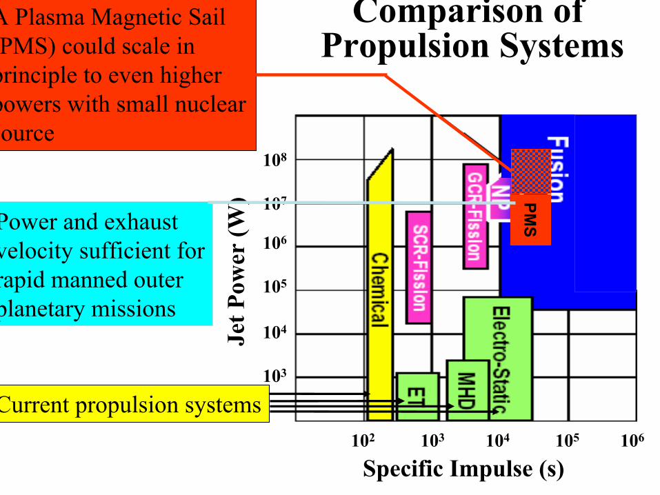
Specific Impulse (s)102 103 104 105 106
Jet P
owe r
(W)
108
107
106
105
104
103
PMSPower and exhaust
velocity sufficient forrapid manned outerplanetary missions
A Plasma Magnetic Sail (PMS) could scale in principle to even higher powers with small nuclear source
Current propulsion systems
Comparison of Propulsion Systems

•In the kinetic case (a), the source particles are lost from the bubble in the transverse direction.
•In the fluid case (b), the source particles are lost predominantly in the downstream direction
Comparison of Kinetic and Fluid Treatment of the Solar Wind in the Plasma Sail Interaction
Contours show the density of the solar wind particlesSource particles are indicated in red.
Changing relative plasma sail size allows for thrust vectoring
Fx ~ 3.4 N
Fy ~ 1.4 N

With magnetic bubble size determined by ambient solar wind pressure, force on plasma sail remains constant as spacecraft moves outward (or inward).
From this scaling, one could imagine moving in toward sun until 20 km plasma sail is reduced to 0.2 m (100,000:1). The scale of the sail is now On the order of the laboratory experiment.
The solar wind pressure is ~ 2 nP. The required pressure to compressdown to the laboratory size is thus (105)2 ×2x10-9 or ~ 20 Pascals. The radial magnetic pressure from a 100 G magnetic field is ~ 40 Pascals.

With the external magnetic field parallel to the polar axis, a radially inward pressure will oppose the plasma expansion, much like the solar wind will do in space. The plasma magnet will thus remain compressed at the meter scale from the kilometer scale.
Helmholtz pair produces external magnetic field (Solar wind surrogate)
Phase I Feasibility Experiments at the University of Washington

. Even though the plasma may be more resistive than the superconducting wires of the MagSail, the huge difference in cross sectional area that the plasma subtends (km2 vs. cm2) minimizes the additional power requirement
The rotating magnetic field (RMF) that sustains the large-scale dipole currents can be constructed out of copper tubing, and driven by a tuned oscillator (10 –100 kHz) with very high efficiency

Tuning Capacitors
Current monitors
IGBT Switching supplies
Energy Storage Caps
0.01 0.012 0.014 0.016 0.018 0.02-500
0
500
Time (msec)
Iant
(A)
I_SouthI_North
Two-Phase Oscillator Driver CircuitsUsed to Obtain Rotating Magnetic Field

MCAS D2 Discharge Only(no RMF) MCAS
In the Experiment the Initial Plasma was Provided by a
Magnetized Cascaded Arc Source (MCAS)
Guide field magnet

-1.5 -1 -0.5 0 0.5 1 1.500.51
1.52
2.53
3.54
4.55
x 1-4 r=4.76
time(10-4 s)
angular position from source centerline
(rad)
Normalized nvi
-1 0 1 2 3 4 5 6
0
0.8
1.6
2.4
3.2
4.0
Time (10-4 s)
dN/dt(1021)
Boron Nitride Washers
Molybdenum Washers
Plasma Discharge
Anode
Cathode
Gas Feed
Vd
Solenoidal Coil
Magnetized Cascaded Arc Source
NvmdtdNF siz 25.015.0 −==
Directed force from plasma gun canbe substantial. From probe measurements:(Idis ~ 2 kA), vs ~ 35 km/s (H)

Experimental Verification of thePlasma Magnet
•Up to 10 kA of plasma current have been generated and sustained
•Ring expansion pressure ~ 40 Pa sufficient for 1:100,000 expansionagainst the solar wind
•Plasma remains linked to RMF antenna in the presence of largeaxially directed plasma pressure from MCAS (~ 8 Pa).
Plasma torus
LangmuirProbe (n, T)


Visible Spectra for Ar Plasma Magnetwith Deuterium “Solar Wind”
350 400 450 500 550 600 650 700 750 800 8500
March12 . 00004.Master.scope
Ar I = Red, Ar II = blue
350 400 450 500 550 600 650 700 750 800 8500
200400600800
100012001400160018002000
Ar I?Ar II
D(H) –
He -Arb
From pictures and radiation → Plasma is fully ionized
C II

-0.2 0 0.2 0.4 0.6 0.8 1
0
0.1
0.2
0.3
0.4
TIME (msec)
nT1/
2 /10e
23
45 V36 V27 V18 V9 V0 V
- 9 V
Probe current for symmetric double probe:
9+9+····9
Current Probe(0.5 V/A)
2 mm x 0.5 mm diamTungsten wire
12
B e ip
e i
eV 1 k(T T )I i tanh , where i n AkT 2 M+ +
+= =
Electron Temperature and Density from Double Langmuir Probe
Te ~ 18 eV

-0.1 0 0.1 0.2 0.3 0.4 0.5 0.6 0.7 0.8TIME (msec)
Increasing gas pressure
86420
-2-4-6-8
-10-12
BzBRMF
(mT)
Magnetic Fields on Axis of the Plasma MagnetB-dot loop tilted at 45° to pick up both Bz and BRMF simultaneously

0 0.05 0.1 0.15 0.2 0.25 0.3 0.35 0.40
0.2
0.4
0.6
0.8
1 100
80
60
40
20
0
Jθ
(kA/m2)Ne(1019 m-3)
Inferred rigid rotor density profile
Radius (m)
Plasma Magnet Density and Current Profile
Total PM current ~ 8 -10 kA
J
Obtain Jθ from Amperes Law:
drdB1J z
0µ=θ
Synchronous electrons⇒ Jθ =neωr
Measured density
-0.050
0.05 BRAW01 1071
-0.050
0.05 BRAW03 1071
-0.050
0.05 BRAW05 1071
-0.050
0.05 BRAW07 1071
-0.050
0.05 BRAW09 1071
-0.050
0.05 BRAW11 1071
-0.020
0.02 BRAW13 1071
-0.010
0.01 BRAW15 1071
0.2 0.3 0.4 0.5 0.6 0.7 0.8-0.01
00.01
TIME ( )
BRAW17 1071
0
4
8
12
16
20
24
28
32
R (cm)
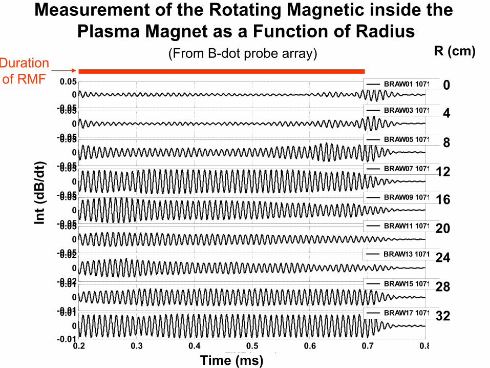
Measurement of the Rotating Magnetic inside the Plasma Magnet as a Function of Radius
(From B-dot probe array)
Time (ms)
Int(
dB/d
t)
Durationof RMF

23m
20
N r1Rr
)mm3(2~
dAdrdnD
dvoln
−
−βηµ⋅
=τ−
⊥⊥ ∫∫
where m is the power by which the density decreases (i.e. 1/rm) from a characteristic surface that intercepts the equatorial plane at R. With a density fall-off of 1/r3 (not critical but less than constant source fed)
Particle confinement in high beta dipolar field
For an R = 10 m RMF antenna with sufficient current (density n0 ~ 1017 m-3) to inflate to a r=100 km bubble:
20N r
Rrln
32~
βηµ
τ⊥
At high β (~1) and Te ~ 20 eV (η⊥ ~ 1.5x10⁻³ Te(eV)-3/2 ⇒ 17 µΩ-m)
π
RrlnnR4~N 0
3
mH N = 1.8 mg τN = 4.5x10⁷ s ~ 1.5 years

Motion of Electrons in Rotating Dipole Field
3-D Calculation of electron motion in rotating magnetic field
Present numerical work is aimed at self consistent motion with Self-generated hall currents

SummaryPhase I Results:
• A plasma magnet was generated and sustained in a space-like environment with a rotating magnetic field
• Sufficient current (~ 10 kA) was produced for inflation of plasma to 10s of km.
• Intercepted significant momentum pressure from an external plasma source without loss of equilibrium
• Plasma and magnetic pressure forces observed to be reactedon to rotating field coils through electromagnetic interaction
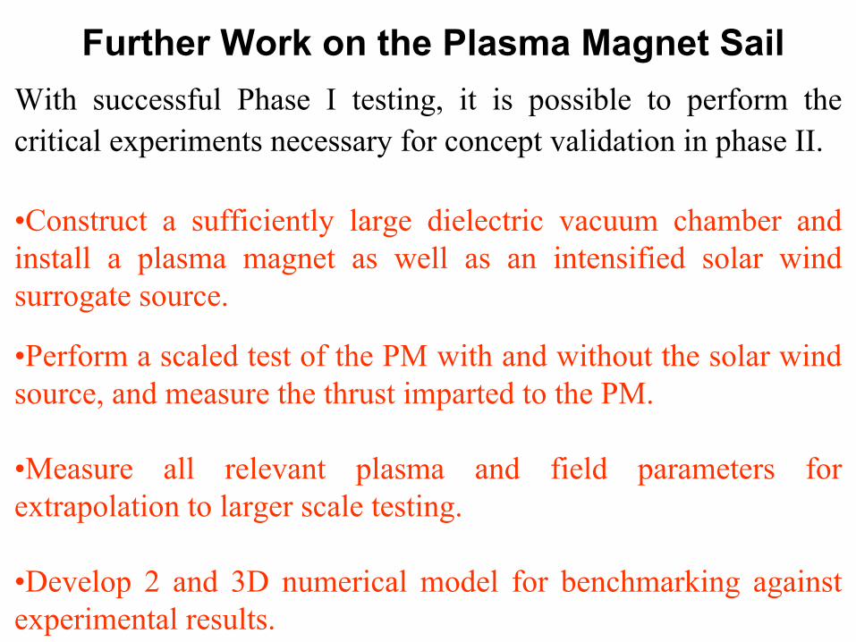
With successful Phase I testing, it is possible to perform the critical experiments necessary for concept validation in phase II.
•Construct a sufficiently large dielectric vacuum chamber and install a plasma magnet as well as an intensified solar wind surrogate source.
•Perform a scaled test of the PM with and without the solar wind source, and measure the thrust imparted to the PM.
•Measure all relevant plasma and field parameters for extrapolation to larger scale testing.
•Develop 2 and 3D numerical model for benchmarking against experimental results.
Further Work on the Plasma Magnet Sail

Lab Solar Wind Source (LSW)
(array of MCAS)
Plasma magnet(pendulum suspended)
Fused Silica Tubes
“Dump” ChamberTi Getter Pumped
Phase II: Concept Validation: Thrust MeasurementAnd Scalability of Plasma Magnetic Sail
• Want to maintain plasma magnet size with smaller antenna to observe expansion
Against Laboratory Solar Wind (LSW) DAntenna ~ 1/4 (0.4 m) – 0.1 m • With Constant force expansion/contraction need ⇒ PLW = PSW = 2 MW• Want ρi/R to scale for kinetic effects ⇒ VLSW ~ VSW ~ 40 km/s
~1 m
~5 m