Embed Size (px)
Citation preview
Université Paris 7 – Denis Diderot Année 2015-2016
Recherche documentaire en anglais
The pipe-in-pipe system
Le système de riser à double enveloppe
Enseignante : Claire Dupuy
Dossier réalisé par : Danet Aguila BuenoEglisneyi Perez Perez
Annabelle Coutant
Page 1 / 50
Page 2 / 50
Table des matières
Introduction.……………………………………………….….4
Texte source……………………………………………….….6
Glossaire anglais-français…………………………………...12
Références…………………………………………………...32Document accessible sous format papier…………….…33Document accessible à distance………………………...33Sites Internet spécialisés…………………….……….….33Glossaire spécialisé………………………………………33
Articles de vulgarisation………………………………….…34
Conclusions………………………………………………….36
Annexe……………………………………………………....39
Page 3 / 50

Introduction
Page 4 / 50
Le texte que nous allons tenter de traduire se concentre sur un nouveau système depipelines, mis en place dans le but de résoudre les dégâts que certains problèmesenvironnementaux causent aux pipelines. En effet, les vibrations, les mouvements de la merou encore les portées libres peuvent endommagés les pipelines, la création de ce nouveau typede pipeline, appelé « pipe-in-pipe system » en anglais et traduit « riser à double enveloppe »en français, s'est révélée indispensable. Les bénéfices de ce nouveau système sont multiples,l'idée originale est de doubler le tuyau pour le renforcer et donc l'empêcher de se tordre ou dese laisser endommager par son environnement naturel, qui est incontrôlable.
Le texte expose deux techniques de mise en place de ce procédé. Tout d'abord les «compliant pipe-in-pipe » (ou « fully bounded pipe-in-pipe»), les deux tuyaux sont totalementliés par les matériaux isolants et subissent les mêmes mouvements, les mêmes vibrations,l’endommagement reste néanmoins moins important de part le dédoublement du tuyau, qui estdonc plus solide pour résister à ces conditions difficiles. Le second procédé est appelé « noncompliant pipe-in-pipe » (ou « unbounded pipe-in-pipe »), les deux tuyaux sont alors séparéspar des plaques isolantes qui permettent aux tuyaux de bouger relativement l'un à l'autre,permettant ainsi de résister à différents types de vibrations qui pourraient survenir au mêmemoment.
Le choix de ce texte s'est fait tout à fait par hasard, en effet nous voulions un sujet surl'environnement, par extension nous avons choisi de s’intéresser aux conséquences que peutavoir l'environnement sur des constructions humaines.
Ce texte semble être utile aux professionnels de la création de pipeline qui peuventchoisir quel procédé leur semble le plus utile dans la mise en place de riser à doubleenveloppe.
Page 5 / 50

Texte source
NB : Le texte n’est pas présenté dans sa version intégrale
Page 6 / 50
Using pipe-in-pipe systems for subsea pipeline vibration control
Abstract
Pipe-in-pipe (PIP) systems are increasingly used in subsea pipeline applications due to theirfavourable thermal insulation capacity. Pipe-in-pipe systems consist of concentric inner andouter pipes, the inner pipe carries hydrocarbons and the outer pipe provides mechanicalprotection to withstand the external hydrostatic pressure. The annulus between the inner andouter pipes is either empty or filled with non-structural insulation material. Due to the specialstructural layout, optimized springs and dashpots can be installed in the annulus and thesystem can be made as a structure-tuned mass damper (TMD) system, which therefore has thepotential to mitigate the pipeline vibrations induced by various sources. This paper proposesusing pipe-in-pipe systems for the subsea pipeline vibration control. The simplification of thepipe-in-pipe system as a non-conventional structure-TMD system is firstly presented. Theeffectiveness of using pipe-in-pipe system to mitigate seismic induced vibration of a subseapipeline with a free span is investigated through numerical simulations by examining theseismic responses of both the traditional and proposed pipe-in-pipe systems based on thedetailed three dimensional (3D) numerical analyses. Two possible design options and therobustness of the proposed system for the pipeline vibration control are discussed. Numericalresults show that the proposed pipe-in-pipe system can effectively suppress seismic inducedvibrations of subsea pipelines without changing too much of the traditional design. Thereforeit could be a cost-effective solution to mitigate pipe vibrations subjected to external dynamicloadings.
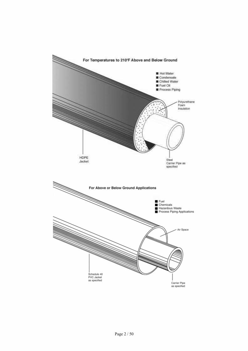
1. IntroductionPipe-in-pipe (PIP) systems are increasingly used in subsea pipeline applications due to theexceptional level of thermal insulation they provide. Pipe-in-pipe systems consist of an innerpipe, conveying the hydrocarbons, and an outer pipe, withstanding the external hydrostaticpressure. The annulus1 between the inner and outer pipes is either empty or filled with non-structural insulation material like mineral wool2, polyurethane foam or aerogel [1]. Thanks totheir exceptional thermal insulation capacity, pipe-in-pipe systems are well suited for thetransportation of hydrocarbons at high pressure and high temperature (HP/HT), preventinghydrate formation and ensuring high discharge temperature at the arrival facility. Today, pipe-in-pipe systems are widely used in the North Sea, the Pacific, Gulf of Mexico and Africa.
Previous studies on subsea pipe-in-pipe systems mainly focused on the structural instabilities.For example, extensive experimental and numerical investigations have been carried out onthe propagation buckling3 and upheaval buckling4 phenomena of subsea pipe-in-pipesystems. Besides these buckling issues, another factor that may severely threaten the integrityof subsea pipelines is the vibrations of free spans induced by various sources such as vortex
Page 7 / 50
shedding or earthquake. It is known that free spans5 can be formed due to the seabedirregularities during installation or the subsequent scouring6 and pipeline horizontalmovements during operation [1]. Pipeline free spans can have a critical influence on the safetyand integrity of the pipeline operation since they are susceptible to vortex-inducedvibrations (VIV)7 and hence fatigue damage. Moreover, subsea pipelines may traversethrough seismic active zones, different seismic hazards may impose severe damages to thepipeline systems. A review of many previous earthquake events reveals that for the buriedpipelines, the permanent ground deformation due to soil failure may have severe influence onthe pipeline integrity. While for the unburied pipelines, both seismic ground waves andpermanent ground deformation can cause severe damage to the pipelines.
Vortex shedding induced vibrations on the subsea pipelines have been systematically studiedby many researchers and various vibration control methods and devices have been developed.Kumar et al. [10] provides an excellent review on these methods. For the seismic responses ofsubsea pipelines, literature review reveals that previous studies are rare. Nath and Soh [11]investigated the harmonic and seismic responses of offshore oil pipelines in proximity to theseabed using finite element method. Datta and Mashaly analyzed the transverse seismicresponses of buried [12] and free-spanning [13] submarine pipelines under random seismicexcitation in the frequency domain based on the spectral approach. Zeinoddini et al. [14]investigated the pipe/water interactions in free-spanning submarine pipelines under severeground excitations. These studies show that severe earthquakes can result in catastrophicdamages to subsea pipelines. How to mitigate these adverse vibrations is deemed important.To the best knowledge of the authors, no open literature reports the vibration control methodfor subsea pipelines when they are subjected to earthquake loadings.
As will be presented in Section 2, a pipe-in-pipe system can be properly designed as a non-conventional structure-tuned mass damper (TMD)8 system by adding optimized springsand dashpots in the annulus, which therefore has the potential to mitigate subsea pipelinevibrations induced by various sources without substantially increasing the manufacturingcosts and weight of the pipe. A TMD is a device consisting of a mass, a spring and a dashpotthat is attached to a vibrating primary structure to attenuate the undesirable vibrations inducedby winds or earthquake loadings. The natural frequency of the TMD is tuned to thefundamental vibration frequency of the primary structure so that the damper will resonant outof phase with the original structure and a large amount of the structural vibrating energy istransferred to the TMD and then dissipated by the damper. Due to its simplicity andeffectiveness, TMD systems have been widely applied since 1970s in many engineeringstructures such as tall buildings, towers and bridges [15]. In the conventional TMD design theauxiliary mass is very small, typically in the order of one to a few percent of the primarystructure. Due to the small mass of the TMD system, a general agreement on the effectivenessof the conventional TMD system is not formed when it is used to mitigate seismic inducedvibrations. Researchers indicate three inherent limitations to the seismic effectiveness of theTMD as summarized by De Angelis et al. [16]: (i) the lack of robustness against deviations indesign parameters; (ii) a high dependency on earthquake frequency content; and (iii) theimpulsive character of the earthquake excitation. To enhance the effectiveness of the TMDsystem, a larger mass ratio (up to 100% and even more in terms of modal quantities) was
Page 8 / 50
introduced by some researchers and this system was normally described as a non-conventional TMD [16].
By adding large mass to the primary building and bridge structure is not technically practicaland may raise safety issues sometimes. To avoid these problems, the masses already presenton the structure to be protected are converted into tuned masses9 in the non-conventionalTMD design, while the structural or architectural function of the structure is retained [16]. Inother words, no additional mass is needed for the non-conventional TMD system. This non-conventional TMD system has been studied by some researchers recently and was applied insome building (e.g. [17], [18], [19], [20], [21], [22] and [23]) and bridge [24] structures.Previous studies show that it is feasible and effective to use non-conventional TMD systemsto reduce the vibrations of primary structures.
This paper proposes using pipe-in-pipe systems for the vibration control of subsea pipelines.It will be demonstrated that this system can be designed as a non-conventional structure-TMDsystem as mentioned above to mitigate pipeline vibrations. The optimum values for thesprings and dashpots installed in the annulus are derived in Section 2. To demonstrate theeffectiveness of the proposed system, a subsea pipe-in-pipe system with a free span subjectedto transverse earthquake is adopted as an example and numerical analyses are carried out byusing the finite element code ANSYS. The detailed numerical modelling is presented inSections 3 and 4 define the earthquake loadings that will be used in the analysis. In Section 5,the seismic responses of the traditional and proposed pipe-in-pipe systems are calculated anddiscussed. Finally in Section 6, two possible design options and the robustness of theproposed system are commented.
2. Pipe-in-pipe as a non-conventional TMD system
2.1. Traditional pipe-in-pipe systemThere are two types of pipe-in-pipe systems commonly used in the offshore industry [25]: (i)fully bounded10 or compliant PIP11, in which the entire annulus is filled with insulationmaterial, and (ii) unbounded12 or non-compliant PIP13, in which the insulation is achievedby wrapping standard size insulation pads14 onto the inner pipe. In the compliant PIP system,load transfer is continuous and the inner and outer pipes deform uniformly. In the non-compliant PIP system the inner and outer pipes can move relative to each other, it is thereforehas the potential to be designed as a structure-TMD system and suitable for the vibrationcontrol when it is subjected to different sources of vibrations.
Fig. 1 shows a typical non-compliant pipe-in-pipe system. A non-compliant PIP normallycomprises an inner pipe, an outer pipe, insulation layer(s), bulkheads15 and centralizers16.Bulkheads are forged fittings attached to the pipe-in-pipe pipeline to maintain structuralintegrity during installation and operation and to serve as installation aids in variety of ways[1]. They are normally welded to both the inner and outer pipes at several locations especiallyat both ends, to fully constrain relative axial motions17 between the inner and outer pipes.The centralizers are generally polymeric rings18 that are clamped on the inner pipe at regularintervals. The spacing between two adjacent centralizers may be 2 m for reeled pipelines19
Page 9 / 50
and can up to 12 m for the S-lay and J-lay installation methods [1]. The purpose of thecentralizers is to effectively centralize the inner pipe to prevent possible damage (likeabrasion or crushing) to the thermal insulation layer during installation and to minimize loadson the insulation layer during installation and operation. To facilitate the installation of innerpipe and centralizers, a gap of 1–10 mm is usually reserved between the centralizers and theouter pipe [6].
2.2. Proposed pipe-in-pipe system and equivalent TMDsimplificationBy examining the structural layout of the non-compliant pipe-in-pipe system as shown in Fig.1 and also by comparing it with the structure-TMD concept mentioned in Section 1, it can beseen that the pipe-in-pipe system has the potential to be designed as a non-conventionalstructure-TMD system by replacing the hard polymeric centralizers by optimized springs anddashpots to connect the inner and outer pipes. By optimizing the spring stiffness and dampingcoefficient20, the inner pipe can vibrate out of phase with the outer pipe and the vibration ofthe systems therefore can be suppressed.
[...]
4. Earthquake loadingsPipe-in-pipe systems are normally located in the subsea, earthquake time histories at theseafloor should be selected as the inputs. However, most of previous earthquake time historiesare recorded at offshore sites, the seafloor recordings are very limited. Moreover, only thetransverse input21 is considered in the present study, this horizontal out-of-plane motion isresulted from the SH wave22, and it is not affected by the upper seawater since water isgenerally regarded as ideal fluid and cannot transmit shear waves23 40]. Therefore earthquakeground motions recorded at onshore sites are used as inputs in the present study.
Three different earthquake loadings are considered in the present study. The first one is anartificially simulated earthquake ground motion based on the spectral representationmethod24 recently proposed by the authors [41]. This earthquake ground motion time historyis generated to be compatible with the design spectrum for soft soil site (class De) specified inthe Australian seismic design code AS1170.4 [42]. In the simulation, the peak groundacceleration (PGA)25 is set as 0.2 g and time duration is 20 s, the sampling frequency andupper cut off frequency are 100 and 25 Hz, respectively. Fig.9(a) shows the simulatedacceleration time history and Fig. 10 compares the response spectra of the generated timehistory and the given model, good match is observed. The second time history is recordedduring the 1989 Loma Prieta earthquake. This is a near-field ground motion26 characterizedwith long-period pulse-like waveforms as shown in Fig.9(b). The last record is from the 1940El Centro earthquake. It is used to represent the far-field earthquake ground motion. Theacceleration time history of this earthquake is shown in Fig.9(c). Table 5 summaries theinformation of the ground motions used in the analysis.
[…]
Page 10 / 50
6. Possible design options and robustness of the proposed system
6.1. Possible design optionsOnly the numerical simulations are carried out in the present study and the hard centralizersare replaced by the optimized springs and dashpot in the numerical model. In real practice,many options can be used to connect the inner and outer pipes. The polyurethane foam(PUF)27 might be one of the options. PUF with different density can provide differentstiffness, and therefore the optimum stiffness can be achieved by selecting the PUF withproper density. The damping requirement can be obtained by adjusting the PUF length alongthe pipe. Moreover, as will be discussed in Section 6.2, the proposed PIP system is quiterobust due to the large mass ratio, i.e., the vibration suppression capability is not greatlyaffected by variations in the stiffness and damping of the connecting spring and dashpot. Thisproperty will significantly facilitate the design.
Another option can be the rotational friction hinge device with spring (RFHDS) as shown inFig. 15. The rotational friction hinge device can provide the optimum damping by adjustingthe preload applied on the bolts and the spring can provide the required stiffness. In realpractice, one end of the device can be welded to the inner pipe, while a small gap will bereserved between the other end and the outer pipe to facilitate installation. The device will beactivated when the outer pipe contacts with it.
7. ConclusionsThis paper proposes using pipe-in-pipe systems for the vibration control of subsea pipelines.This system takes advantage of the special structural layout of the pipe-in-pipe systems andcan be designed as a non-conventional structure-TMD system. The outer pipe acts as the mainsystem and the inner pipe performs as the TMD mass. The optimized springs and dashpots areinstalled in the annulus between the outer and inner pipes and provide stiffness and dampingto the TMD mass. To examine the effectiveness of the proposed system to mitigate seismicinduced vibrations of a subsea pipeline with a free span, detailed 3D FE analyses are carriedout by using finite element code ANSYS. Numerical results show that the proposed systemnot only significantly suppresses the vibration of the outer pipe but also obviously reduces thevibration of the inner pipe without any additional mass. Moreover, the system is effective androbustness to different types of earthquakes. This system will have great application potentialsto control the vibrations of subsea pipelines induced by various sources.
Page 11 / 50

Glossaire Anglais-Français
Page 12 / 50
annulus1
Catégorie syntaxique : Nom
Définition : a part, structure, or marking resembling a ring
➢ Source : http://www.merriam-webster.com/
Traduction : Espace annulaire
Définition française : Annulaire: Qui a une forme d'anneau. Dans ce cas c'est l'espacequi a une forme d'anneau
➢ Source : http://www.larousse.fr/
En contexte :
1. « Ce numéro s’intéresse plus particulièrement à la réhabilitation par tubage desconduites d’eau à l’aide de tubes en polyéthylène à haute densité (PEHD), avec
injection de coulis dans l’espace annulaire compris entre le tube intérieur et laconduite existante. »
➢ Source : http://www.nrc-cnrc.gc.ca/
2. « Dans le cadre du diagnostic gaz, le contrôle vise à vérifier que si l'espaceannulaire à la pénétration de la tuyauterie dans l'habitation est visible, il est bienobturé. »
➢ Source : http://www.formation.xpair.com/
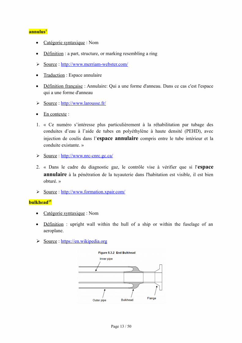
bulkhead15
Catégorie syntaxique : Nom
Définition : upright wall within the hull of a ship or within the fuselage of anaeroplane.
➢ Source : https://en.wikipedia.org
Page 13 / 50
Traduction : Paroi
Définition française : Mur exécuté dans un terrain, depuis la surface, destiné àsoutenir, après terrassement de la fouille, les parois de l'excavation, à en assurerl'étanchéité et à jouer, dans certains cas, le rôle de mur porteur.
➢ Source : Larousse.fr : encyclopédie et dictionnaire gratuits en ligne
www.larousse.fr
En contexte :
1. « L'outil d'inspection interne dont la PII se sert pour déterminer l'épaisseur de la
paroi de la conduite mesure l'épaisseur à l'aide d'une technique utilisant le temps deréflexion d'ultrasons. »
➢ Source : http://bst-tsb.gc.ca/
2. « Elle circule ensuite dans l'autre sens, entre la paroi externe de la conduite dedistribution et la paroi interne du tube à ailettes vers le collecteur de condensat. »
➢ So urce : https://www.armstronginternational.com/
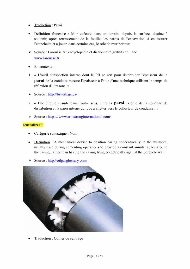
centralizer16
Catégorie syntaxique : Nom
Définition : A mechanical device to position casing concentrically in the wellbore,usually used during cementing operations to provide a constant annular space aroundthe casing, rather than having the casing lying eccentrically against the borehole wall.
➢ Source : http://oilgasglossary.com/
Traduction : Collier de centrage
Page 14 / 50
Définition française : Utilisé pour isoler un pipeline d’un fourreau en acier ou en bétonpour les traversées de route, de chemin, de voie ferrée et répondent parfaitement auxexigences de la protection cathodique.
➢ Source : http://www.ipsifrance.com/
En contexte :
1. « Ce nouveau système de colliers de centrage sans métal et sans visserie offreplusieurs avantages :
- Rapidité de montage : Les segments s'emboîtent les uns dans les autres sans difficulté, lorsque le dernier segment est emboîté, on insère les chevilles de blocage entre chaque segment.
- Durée dans le temps : Aucun risque d'oxydation, car étant conçus sans métal ces colliers ne craignent pas la corrosion.
5 largeurs de segments sont proposées (en mm) et en plusieurs hauteurs de patins »
➢ Source : http://www.erfi.fr/
2. « Les colliers de centrage type MA sont livrables pour des diamètres extérieurs detuyauterie de 400 mm et plus. »
➢ Source : http://www.alphapipe.fr/
compliant PIP11
Catégorie syntaxique : Syntagme nominal
Synonyme de « fully bounded »
Définition : The compliant systems have a connection between the inner and outerpipes at close intervals either every two pipe joints by tulip, or by donut plate. In thiscase, the inner and the outer pipes expand uniformly along the pipeline and loadtransfer is continuous.
➢ Source : Thermal expansion of pipe-in-pipe systemhttp://www.sciencedirect.com/
Définition française : Les deux conduites sont totalement liées par des matériauxisolants. Elles subissent donc les mêmes mouvements et les mêmes vibrations.
damping coefficient20
Catégorie syntaxique : Syntagme nominal
Définition : A dimensionless measure describing how oscillations in a system decayafter a disturbance.
Page 15 / 50
➢ Source : https://en.wikipedia.org
Traduction : Amortissement
Définition française : Une grandeur sans dimension caractérisant l'évolution et ladécroissance au cours du temps des oscillations d'un système physique.
En contexte :
1. « Ce bulletin d'interprétation annule et remplace le bulletin IT-482 du 30 novembre
1981, intitulé Déduction pour amortissement - Pipe-lines, et le communiquéspécial du 28 février 1986 qui s'y rattache. »
➢ Source : http://www.cra-arc.gc.ca/
2. « Concernant les gazoducs de GRT gaz, les durées d'amortissement sont de 50 anspour les lignes, et de 30 ans pour les stations de compression. »
➢ Source : Le transport par pipeline: aspects économiques et environnementaux
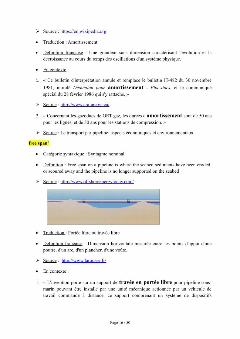
free span5
Catégorie syntaxique : Syntagme nominal
Définition : Free span on a pipeline is where the seabed sediments have been eroded,or scoured away and the pipeline is no longer supported on the seabed
➢ Source : http://www.offshoreenergytoday.com/
Traduction : Portée libre ou travée libre
Définition française : Dimension horizontale mesurée entre les points d'appui d'unepoutre, d'un arc, d'un plancher, d'une voûte.
➢ Source : http://www.larousse.fr/
En contexte :
1. « L'invention porte sur un support de travée en portée libre pour pipeline sous-marin pouvant être installé par une unité mécanique actionnée par un véhicule detravail commandé à distance, ce support comprenant un système de dispositifs
Page 16 / 50
permettant d'utiliser une pile-colonne continue constituée d'une section carrée creuseou de tout autre section appropriée laminée ou assemblée. »
➢ Source : Brevet - Support mécanique de travée en portée libre pour pipeline avecenfouissement d'ancre suceuse
2. « En ce qui concerne l'accès, veuillez consulter les énoncés opérationnels Ponts deglace et remblais de neige, Ponts à portée libre et Passages à gué temporaires. »
➢ Source : http://www.dfo-mpo.gc.ca/
fully bounded10
Catégorie syntaxique : Syntagme adjectival
Voir « Compliant PIP »
Insulation pad14
Catégorie syntaxique : Syntagme nominal
Définition : The four insulation blocks are combined to form a cylindrical insulationbarrel and connected mutually through lock catches to form an insulation barrelintegral body; each insulation block is composed of an integrated metal plateprotective part in the outer layer and an insulation pad in the inner layer.
➢ Source : Brevet CN 203892808 U
Traduction : Plaque isolante
Définition française : La présente invention concerne la conception et la réalisationdes tuyaux à double enveloppe, tels notamment que ceux qui sont destinés à êtreraccordés bout à bout pour constituer des canalisations, ou qui sont plusparticulièrement construits pour former des canalisations à poser au fond des mers,pour servir à véhiculer des produits pétroliers, sous forme liquide et/ou gazeuse.
➢ Source : Brevet WO 1997037166 A1
En contexte :
1. « L'invention porte sur une plaque isolante en laine minérale (5) pour laclimatisation, laquelle plaque comprend une structure en laine minérale (1, 11) avecune cavité traversante formant conduite ouverte aux deux extrémités. »
➢ Source : Brevet WO 2012072872 A1
2. « Plaque isolante collable, résistant aux charges de hautes températures, enparticulier à la charge de température d'un fil de chauffage porté au rouge, à base d'unematière thermiquement isolante minérale, fortement dispersée, et d'un durcisseur. »
Page 17 / 50
➢ Source : EP 0048947 B1
mineral wool2
Catégorie syntaxique : Syntagme nominal
Définition : An inorganic fibrous substance that is produced by steam blasting andcooling molten glass or a similar substance and is used as an insulator and a filteringmaterial.
Traduction : Laine minérale
Définition française : Matériau de consistance laineuse , fait de fibres minéralesamorphes (fibres de silicates vitreuses artificielles) à « orientation aléatoire » obtenuespar fusion puis fibrage de roche, de verre ou de laitier.
➢ Source : https://fr.wikipedia.org
En contexte :
1. « Les isolants en laine minérale sont les plus utilisés de tous les isolants. Que cesoit en laine de verre, en laine de roche ou en verre cellulaire, ils sont très efficacespour l'isolation thermique et acoustique à moindre prix. »
➢ Source : http://www.toutsurlisolation.com/
2. « La laine de verre reste très utilisée dans le domaine du bâtiment et permet parailleurs de lutter contre les incendies puisqu'elle est incombustible. »
➢ Source : http://www.futura-sciences.com/
near-field ground motion26
Catégorie syntaxique : Syntagme nominal
2. Définition : A useful criterion to define the near field zone is related to the comparisonof the source dimension with the source to site distance. The near field ground motionscan produce ground motion characteristic different from that in the far field because ofthe directivity and fling step effects.
➢ Source : http://www.iitk.ac.in/nicee/wcee/article/WCEE2012_4147.pdf
Traduction : Mouvement du terrain
Définition française : station sismique souterraine
➢ Source : La surveillance sismique sous-marine: la situation en France et dans le monde
En contexte :
Page 18 / 50
1. « Les mouvements de terrain sont des phénomènes naturels d’origines trèsdiverses. »
➢ Source : Ministère de l'environnement, de l'énergie et de la mer.http://www.developpement-durable.gouv.fr/Le-risque-mouvement-de-terrain.html
2. « Les mouvements de terrain peuvent être lents ou rapides. »
➢ Source : http://www.developpement-durable.gouv.fr/IMG/pdf/mvmt_terrain.pdf
non-compliant PIP13
Catégorie syntaxique : Syntagme nominal
Antonyme de « compliant PIP »
Définition : The insulation is achieved by wrapping standard size insulation pads ontothe inner pipe.
Définition française : Les deux conduites sont reliées par des plaques isolantes, ellespeuvent donc subir différents dommages car elles ne réagiront pas toujours aux mêmesvibrations.
peak ground acceleration (PGA)25
Catégorie syntaxique : Syntagme nominal
Définition : Peak ground acceleration (PGA) is equal to the maximum groundacceleration that occurred during earthquake shaking at a location. PGA is equal to theamplitude of the largest absolute acceleration recorded on an accelerogram at a siteduring a particular earthquake. Earthquake shaking generally occurs in all threedirections. Therefore, PGA is often split into the horizontal and vertical components.Horizontal PGAs are generally larger than those in the vertical direction but this is notalways true, especially close to large earthquakes. PGA is an important parameter(also known as an intensity measure) for earthtquake engineering, The design basisearthquake ground motion (DBEGM) is often defined in terms of PGA.
➢ Source : www.wikipedia.org
Traduction : Accélération maximale du sol
Définition française : L'accélération maximale du sol (en anglais : Peak GroundAcceleration ou PGA) est un paramètre caractérisant le mouvement de sols soumis àdes ondes sismiques ; il est lié à la vitesse du sol se déplaçant lors d'un séisme. Cesdeux paramètres dépendent de l'intensité de la secousse, mais aussi de la naturegéologique du sous- sol. Pour les petits séismes (magnitude < 3), c’est surtoutl’accélération qui est ressentie par la population et rarement les mouvements verticaux(Wu et al., 2003). Les dommages aux structures augmentent avec le PGA en lien avec
Page 19 / 50
les hautes vitesses. C'est l'un des principaux paramètres utilisés dans la conception destructures parasismiques. Il est très utilisé dans le calcul de l'aléa- sismique.
➢ Source : www.wikipedia.org
En contexte :
1. « Cette valeur d'accélération maximale du sol qui est la plus grande valeur(absolue) qu'on peut obtenir à partir de l'accélérogramme sur ce site. »
➢ Source : Livre: Étude pluridisciplinaire de la stabilité des pentes par BerthoumieuxJunior Jean
2. « L'acceleration maximale du sol correspond a la valeur asymptotique. »
➢ Source : Calcul sismique Validation du calcul de spectres transfères a partir desspectres de réponse élastique EUROCODE 8http://www.phmaurel.fr/seis-spec-001.pdf
polymeric ring18
Catégorie syntaxique : Syntagme nominal
Définition : A flexible ring is disclosed comprising one or more coiled springs and/orpolymeric ring(s). In some embodiments, the coiled spring envelopes one or moreinner coiled springs.
➢ Source : Brevet US 9039574 B2
Traduction : Anneau polymère
Définition française : Joints d'étanchéité et polymères permettant de bloquer toutefuite de fluide au travers du joint.
➢ Source : Brevet EP 0152406 A1
En contexte :
1. « L'anneau polymère assure la fonction d'étanchéité initiale pendant les fuites àune faible pression différentielle (par ex. moins de 10 psid), et une fois que l'anneaupolymère forme une étanchéité sur l'arbre ou la chemise d'arbre, une pressiond'étanchéité accrue charge l'anneau polymère contre l'anneau d'étanchéité/anti-extrusion métallique, entraînant sa déformation de sorte que le diamètre intérieur del'anneau métallique entre en contact avec l'arbre ou la chemise d'arbre pour former unsecond joint. »
➢ Source : Brevet WO 2013154644 A2
Page 20 / 50
2. « Ensemble moule (100) selon la revendication 2 comprenant en outre un systèmed'inspection de lentille automatique opérant pour vérifier si une lentille formée
comprend un défaut d'excès d'anneau polymère. »
➢ Source : Brevet EP 2081756 B1
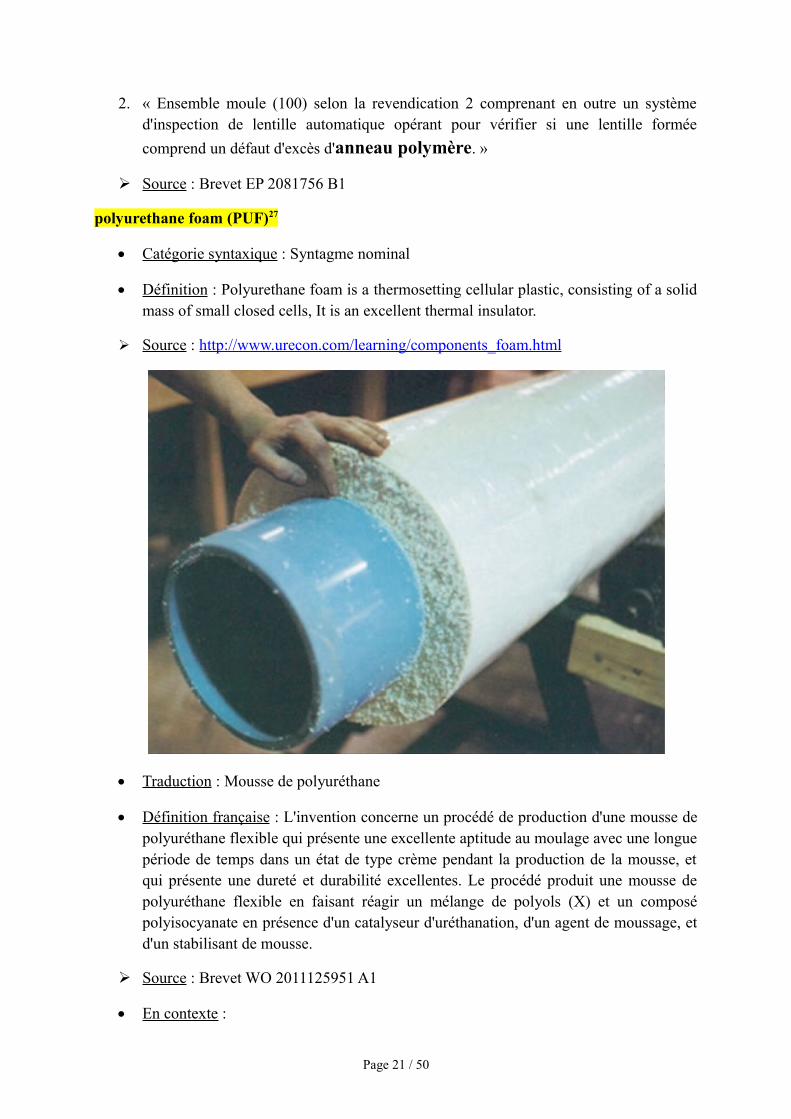
polyurethane foam (PUF)27
Catégorie syntaxique : Syntagme nominal
Définition : Polyurethane foam is a thermosetting cellular plastic, consisting of a solidmass of small closed cells, It is an excellent thermal insulator.
➢ Source : http://www.urecon.com/learning/components_foam.html
Traduction : Mousse de polyuréthane
Définition française : L'invention concerne un procédé de production d'une mousse depolyuréthane flexible qui présente une excellente aptitude au moulage avec une longuepériode de temps dans un état de type crème pendant la production de la mousse, etqui présente une dureté et durabilité excellentes. Le procédé produit une mousse depolyuréthane flexible en faisant réagir un mélange de polyols (X) et un composépolyisocyanate en présence d'un catalyseur d'uréthanation, d'un agent de moussage, etd'un stabilisant de mousse.
➢ Source : Brevet WO 2011125951 A1
En contexte :
Page 21 / 50
1. « La présente invention a pour objet une mousse de polyuréthane pistolée rigide,formée en utilisant du cyclopentane au titre d’agent d'expansion, et qui peut êtreemployée pour isoler des tuyaux du fait de sa capacité à résister à des températuresélevées (>120 °C). »
➢ Source : Brevet WO 2006044365 A1
2. « L'invention concerne des tuyaux doubles calorifugés (5, 6) comportant une couche
calorifuge (15) de mousse de polyuréthane rigide, qui possèdent un effetcalorifuge amélioré et sont dépourvus de ponts thermique. »
Source : Brevet EP 1152879 A1
propagation buckling3
Catégorie syntaxique : Syntagme nominal
Définition : A mathematical instability, leading to a failure mode.
➢ Source : https://en.wikipedia.org/
Traduction : Flambage
Définition française : Phénomène physique relevant des principes de la résistance desmatériaux. Lorsqu'une structure est compressée dans le sens de la longueur, elle atendance à fléchir perpendiculairement à l'axe de la force appliquée, en raison d'unphénomène d'instabilité élastique.
➢ Source : http://www.futura-sciences.com/
En contexte :
1. « Forterre de l’IUSTI et ses collaborateurs à Harvard, USA. ont montré récemment
que ce mouvement rapide se faisait par l’intermédiaire d’une instabilité de flambageen relation avec la forme en coquille des feuilles du piège qu’elles constituent. »
➢ Source : http://mavoiescientifique.onisep.fr/
2. « Dans le cas du flambage, les formules établies tiennent compte des déformationsqui ne peuvent plus être supposées infiniment petites et négligées comme dans leschapitres précédents, de même, les forces extérieures ne sont plus proportionnelles auxdéformations. »
➢ Source : http://www.technologuepro.com/
reeled pipeline19
Catégorie syntaxique : Syntagme nominal
Page 22 / 50
Définition : Pipeline reeling is a well established method for offshore installation ofrigid steel pipelines and risers. The basic process of loading stalks of pipe that havebeen fabricated onshore onto large reels before transit to the worksite, unspooling,straightening and lay is generally well known.
➢ Source : https://www.onepetro.org/conference-paper/ISOPE-I-08-395
Traduction : Une bobine
Définition française : Petit cylindre à rebords sur lequel on enroule des matièressouples (câbles, cordes, fils, rubans, films, etc.).
➢ Source : www.larousse.fr
En contexte :
1. « Une bobine convertisseuse de signaux est encastrée entre les deux moitiés et captela déflection du diaphragme.Cette bobine encastrée est aussi recouverte d'une coucheinoxydable, de telle sorte que le capteur entier présente une parfaite inoxydabilité vis àvis du fluide. »
➢ Source: http://hmf.enseeiht.fr/travaux/CD9899/travaux/optsee/hym/nome01/pa02.htm
2. « Une bobine inductance shunt permettant de compenser l’effet dit « capacitif » descâbles sous-marins et souterrains. »
➢ Source: Arrêté préfectoral du 3 juillet 2015http://www.seine-maritime.gouv.fr/content/download/19406/145421/file/4%20-%20Avis%20Approbation%20Poste%20de%20Sainneville%20Raccordement%20%C3%A9lectrique.pdf
relative axial motion17
Catégorie syntaxique : Syntagme nominal
Définition : A flexible coupling having means to accommodate relative movementbetween the coupled members along their rotational axes.
➢ Source: US patent subclass 464/162Coupling facilitates relative axial motion between coupled membershttp://www.patentec.com/data/class/defs/464/162.html
Traduction : Mouvement axial relatif
Définition française : Mouvement d'un corps considéré par rapport à des repères quine sont pas nécessairement fixes
➢ Source : CNRTL (Centre National des Ressources Textuelles et Lexicales)http://www.cnrtl.fr/lexicographie/mouvement
Page 23 / 50
En contexte :
1. « l'outil étant conçu pour être forcé vers le bas pour fournir le mouvement axialrelatif, et de ce fait, pour activer le dispositif d'étanchéité en déformant les deuxbagues d'étanchéité (15, 16), la garniture étant une bague (10), captive maisdéplaçable axialement en mouvement relatif, supportée par l'outil porteur, par unmanchon (17) passant, vers le bas, entre les surfaces de coin des deux baguesd'étanchéité, grâce à quoi l'outil porteur, le dispositif d'étanchéité et la bague degarniture forment un ensemble unitaire. »
➢ Source : Dispositif de suspension de tubages EP 0552525 B1
2. « Avec un mouvement axial relatif entre la pièce et l'instrument de mesure. Lemouvement doit être guidé le long d'une ligne de contour de forme théoriquementparfaite, étant en position correcte par rapport à l'axe de référence. »
➢ Source : Tolérances et écarts dimensionnels, Géométriques et d'états de surface.
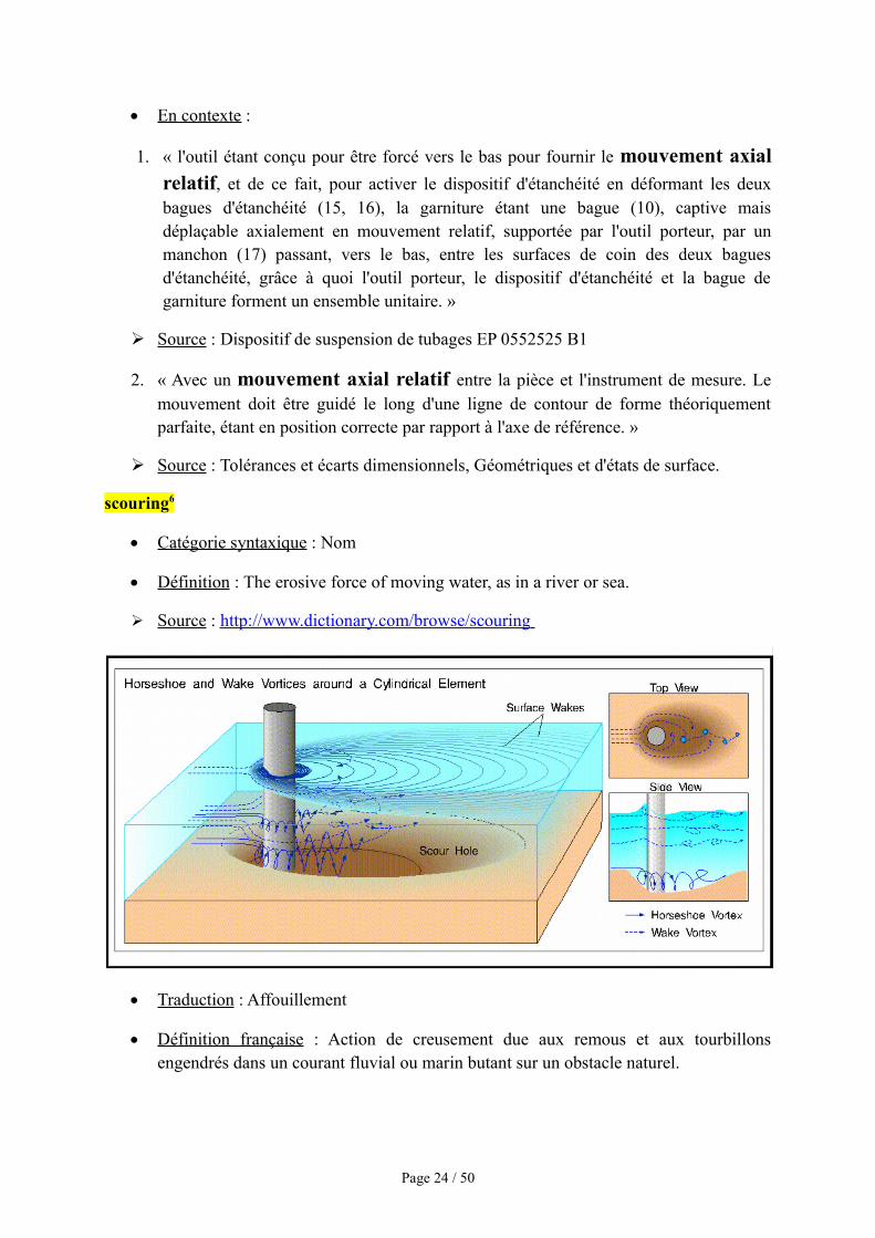
scouring6
Catégorie syntaxique : Nom
Définition : The erosive force of moving water, as in a river or sea.
➢ Source : http://www.dictionary.com/browse/scouring
Traduction : Affouillement
Définition française : Action de creusement due aux remous et aux tourbillonsengendrés dans un courant fluvial ou marin butant sur un obstacle naturel.
Page 24 / 50
➢ Source:http://www.larousse.fr/dictionnaires/francais/affouillement/1515#rEG7IBaqPhAR4LR6.99
En contexte :
1. « L’utilisation des géotextiles pour la protection du littoral suit les techniques déjàmise en place pour les protections classiques en enrochements (brise-lames, épis,perrés). Considérée comme une solution légère, économique et réversible, elle consisteà pomper du sable à l’aide d’une drague et à remplir les tubes posés sur un tapis anti
affouillement. »
➢ Source : Conférence Méditerranéenne Côtière et Maritime http://www.paralia.fr/cmcm/e02-10-farnole.pdf
2. « La présence d’avalanches cisaillées par un écoulement d’eau a aussi été mise en
évidence lors de la création de fossés d’affouillement des piles de pont. »
➢ Source : Stabilité et dynamique de pentes granulaires sous-marines Thèse, école doctorale de l’école Polytechnique.
SH wave23
• Catégorie syntaxique : Syntagme nominal
• Définition : A shear wave that is polarized so that its particle motion and direction ofpropagation are contained in a horizontal plane.
➢ Source : Oilfield Glossary, Schlumberger,
http://www.glossary.oilfield.slb.com/Terms/s/sh-wave.aspx
Synonye de « shear wave »
shear wave24
• Catégorie syntaxique : Syntagme nominal
• Définition : Also known as S-wave, an elastic body wave in which particles oscillateperpendicular to the direction in which the wave propagates. S-waves are generated bymost land seismic sources, but not by air guns. Recording of S-waves requiresreceivers coupled to the solid Earth. Interpretation of S-waves can allow determinationof rock properties such as fracture density and orientation, Poisson's ratio and rocktype by crossplotting P-wave and S-wave velocities, and by other techniques.
➢ Source: Oilfield Glossary, Schlumberger,http://www.glossary.oilfield.slb.com/en/Terms/s/shear_wave.aspx
• Traduction : Onde de cisaillement
Page 25 / 50
• Définition française : Ondes sismiques secondaires qui se propagent plus lentementque les ondes primaires P. Elles consistent en vibrations élastiques transversales,perpendiculaires à la direction de propagation. Les ondes S ne peuvent se propagerdans un fluide.
➢ Source : http://www.chambon.ac-versailles.fr/science/geol/seism/onde.htm
• En contexte :
1. « Utilisation des ondes de cisaillement ultrasonores pour l'imagerie d'élasticitédes tissus biologiques »
➢ Source : Manuscrit de Melouka Elkateb Hachemi, Samuel Callé et Jean-PierreRemeniéras, Université F. Rabelais http://documents.irevues.inist.fr/bitstream/handle/2042/6715/04"Elkateb+(coul).pdf?sequence=1
2. « Les ondes S, qui elles correspondent à un cisaillement, ne se propagent que dansles solides car ces derniers offrent une résistance au cisaillement (contrairement auxfluides) »
➢ Source : Origine des ondes S dans le noyau, Cédric Lémery, ENS Lyonhttp://planet-terre.ens-lyon.fr/article/ondes-s-et-noyau.xml
spectral representation method25
• Catégorie syntaxique : Syntagme nominal
• Définition : The spectral theorem yields that, under certain conditions, stationaryprocesses can be decomposed in terms of regular underlying oscillations whosemagnitudes are random variables.
➢ Source : https://classes.soe.ucsc.edu/ams263/Fall05/notes_2.pdf
• Traduction : Procédé de représentation spectrale
• En contexte :
1. « Ce procédé comprend des étapes consistant à transformer des segments temporels
de signaux de données numérisées en une représentation spectrale fréquentielledes données numérisées. »
➢ Source : Reverso Contexthttp://context.reverso.net/traduction/anglais-francais/spectral+representation+method?utm_source=reversoweb&utm_medium=contextresults&utm_campaign=resultpage
Page 26 / 50
2. « Pour montrer l'intérêt de cette méthode, imaginer une distribution spectrale depuissance telle que celle de la figure suivante […] (largeur de bande du canal 8 M Hzdéfinie par les marqueurs). »
➢ Source : Lingueehttp://www.linguee.fr/francais-anglais/search?source=auto&query=méthode+de+représentation+spectrale
transverse input21
• Catégorie syntaxique : Syntagme nominal
• Définition : Data entered into a computer for processing and extending across adirection.
➢ Source : WordReference.http://www.wordreference.com/definition/transverse input
• Traduction : Donnée transversale
• En contexte :
1. « Cette technologie s’appuie sur la propagation d’ondes ultrasonores de basse
fréquence dans toute la longueur du tuyau pour recueillir des donnéestransversales et rechercher des variations dans l’épaisseur de la paroi. »
➢ Source : Olympus : Your Vision, Our Futurehttp://www.olympus-ims.com/fr/news/100-id.184550446.html
2. « Le fait que les analyses soient basées sur des données transversales limiteencore les déductions qui peuvent être faites […] »
➢ Source : Linguee : Dictionnaire anglais-français (et autres langues)http://www.linguee.fr/francais-anglais/traduction/données+transversales.html
tuned mass damper (TMD)9
• Catégorie syntaxique : Syntagme nominal
• Définition : A tuned mass damper, also known as a harmonic absorber, is a devicemounted in structures to reduce the amplitude of mechanical vibrations. Theirapplication can prevent discomfort, damage, or outright structural failure. They arefrequently used in power transmission, automobiles, and buildings.
➢ Source : Wikipedia, The Free Encyclipediahttps://en.wikipedia.org/wiki/Tuned_mass_damper
Page 27 / 50
• Traduction : Amortisseur harmonique / amortisseur dynamique accordé (ADA)
• Définition française : Un amortisseur harmonique ou amortisseur dynamique accordé(ADA) est un dispositif installé sur des structures du génie civil (ponts, viaducs,antennes...) permettant la réduction des oscillations provoquées par le vent (ou d'autrescauses). C'est un oscillateur accordé et amorti, généralement dissimulé au sommet dela structure, et couplé au mouvement de cette dernière, de telle manière qu'idéalementil oscille en opposition de phase avec elle et récupère ainsi de l'énergie.
➢ Source : Wikipedia, The Free Encyclopediahttps://fr.wikipedia.org/wiki/Amortisseur_harmonique
• En contexte :
1. « Ce dispositif, le plus volumineux au monde, est un amortisseur harmonique. »
➢ Source : La sphère qui protège la tour http://www.labosvj.fr/actu/news/la-sphere-qui-protege-la-tour/
2. « Taylor Devices conçoit, fabrique et vend des amortisseurs visqueux, absorbeurs de
choc, amortisseurs parasismiques, amortisseurs dynamiques accordés […] »
➢ Source : Taylor Devices, Europe http://www.taylordevices.eu/fr/activities_details.php?id_cat=2
unbounded12
• Catégorie syntaxique : Adjectif qualitatif
• Définition : Having no limits, borders or bounds.
➢ Source : WordReference.com, Online Language Dictionarieshttp://www.wordreference.com/definition/unbounded
• Traduction : Illimité, sans bornes, sans frontières
• Définition française : Qui n'est pas limité, qui est sans restrictions ou sans terme fixé.
➢ Source : Larousse.fr : encyclopédie et dictionnaires gratuits en lignehttp://www.larousse.fr/dictionnaires/francais/illimité/41550?q=illimité#41452
• En contexte :
1. « Là aussi, il y aura un accès illimité à une électricité produite grâce au gaz naturel[…] »
➢ Source : Linguee : Dictionnaire anglais-français (et autres langues)http://www.linguee.fr/search?query=illimité
Page 28 / 50
2. « Le nombre de processus chimiques […] et de substances substances organiques etinorganiques lié à des dangers toxiques et à des risques d'explosion est pratiquement
illimité. »
➢ Source : Linguee : Dictionnaire anglais-français (et autres langues)http://www.linguee.fr/search?query=illimité
upheaval buckling 4
• Catégorie syntaxique : Syntagme nominal
• Définition : Upheaval buckling refers to the phenomenon that occurs when trenchedpipelines are subjected to axial compression forces as a result of high temperature andpressure. The pipeline experiences a large vertical displacement and push up throughthe soil cover, leaving the pipeline exposes to impact from anchors or trawl boards.Excessive bending is another failure mode.
➢ Source: GeoLine, Consulting Geotechnical and Pipeline Engineershttp://www.geoline.dk/pipepg5.shtml
• Traduction : Flambage par soulévement
• Définition française : Le flambage par soulèvement est un phénomène bien connudans les pipelines enfouis: il peut conduire à des soulèvements importants d'unpipeline, et est causé par l'interaction entre la force de compression longitudinaleprésente durant l'opération et les irrégularités de courbure dans le profil.
➢ Source : Glosbe, https://glosbe.com/en/fr/upheaval buckling
• En contexte :
1. « Le flambage par soulèvement est un phénomène bien connu (Palmer, 2003). »
➢ Source : Collection mémoires et thèses électroniques, Université Laval. Chapitre 4,Mécanismes de dégradation du pergélisol et problèmes géotechniques reliées auxinfrastructures (4.4.2).http://theses.ulaval.ca/archimede/fichiers/26000/ch05.html
2. « Note 1 à l’article : Le flambage par soulèvement est habituellement induit pardes modifications du pergélisol. »
➢ Source : ISO : Plateforme de consultation en ligne (OBP). ISO 19906:2010(fr),Industries du pétrole et du gaz naturel — Structures arctiques en mer (3.82)https://www.iso.org/obp/ui/fr/#iso:std:iso:19906:ed-1:v1:fr
vortex-induced vibration (VIV)7
Page 29 / 50
• Catégorie syntaxique : Syntagme nominal
• Définition : In fluid dynamics, vortex-induced vibrations (VIV) are motions inducedon bodies interacting with an external fluid flow, produced by – or the motionproducing – periodical irregularities on this flow.
➢ Source : Wikipedia, The Free Encyclopediahttps://en.wikipedia.org/wiki/Vortex-induced_vibration
• Traduction : Vibrations induites par vortex
• Définition française : Les vibrations induites par vortex (VIV) d’un solide immergéinteragissant fortement avec son sillage sont des oscillations auto-entretenues. LesVIV peuvent atteindre des amplitudes significatives lorsque la fréquence dudétachement tourbillonnaire est proche d’une des fréquences propres de la dynamiquedu solide, et constituent donc un mécanisme d’interactions fluide/structure intéressantpour extraire de l’énergie d’un écoulement
➢ Source : Clement Grouthier. Récupération d’énergie et vibrations induites par vortexde structures flexibles. Mécanique des fluides [physics.class-ph]. Ecole PolytechniqueX, 2013. Français. https://pastel.archives-ouvertes.fr/pastel-00875763
• En contexte :
1. « Ces vibrations, induites par le détachement périodique de tourbillons dans le
sillage de la structure (d'où le nom vibrations induites par vortex),endommagent par fatigue les câbles et les éléments de tuyauteries qui relient à laplateforme d'exploitation les têtes de puits de pétrole situés au niveau du sol marin. »
➢ Source : ParisTech, Institut des Sciences et Technologieshttps://pastel.archives-ouvertes.fr/pastel-00005094/
2. « Nous utilisons un modèle asymptotique développé à faible nombre de Reynolds afin
d’étudier la dynamique forcée d’un cylindre circulaire soumis à des vibrationsinduites par vortex. »
➢ Source:http://documents.irevues.inist.fr/bitstream/handle/2042/46563/cfm2011_979.pdf?sequence=1
Vortex shedding8
• Catégorie syntaxique : Syntagme nominal
• Définition : In fluid dynamics, vortex shedding is an oscillating flow that takes placewhen a fluid such as air or water flows past a bluff (as opposed to streamlined) body atcertain velocities, depending on the size and shape of the body. In this flow, vortices
Page 30 / 50
are created at the back of the body and detach periodically from either side of thebody. The fluid flow past the object creates alternating low-pressure vortices on thedownstream side of the object. The object will tend to move toward the low-pressurezone.
➢ Source : Wikipedia, The Free Encyclopediahttps://en.wikipedia.org/wiki/Vortex_shedding
• Traduction : Allée de tourbillons de Karman
• Définition française : Une allée de tourbillons de Karman ou allée de Bénard-VonKarman est un motif périodique de tourbillons causés par la séparation instable d'unécoulement autour de corps peu profilés. Une allée de tourbillons ne peut s'observerqu'à l'intérieur d'un intervalle donné de nombres de Reynolds, généralement entre unsystème de tourbillons attaché à l'obstacle et la turbulence. Lorsqu'un tourbillon sedétache, un écoulement dissymétrique se forme autour du corps, ce qui modifie ladistribution des pressions. Cela signifie que la séparation alternée des tourbillons peutcréer sur ce corps une portance périodique, cause de vibrations.
➢ Source : Wikipedia, The Free Encyclopediahttps://fr.wikipedia.org/wiki/Allée_de_tourbillons_de_Karman#Description
• En contexte :
1. « Lorsque l'écoulement est perturbé par un obstacle, on observe un détachement
tourbillonnaire autour de cet obstacle: les allées de Von Karman, dont le
détachement de ces tourbillons est périodique et de sens alternés. »
➢ Source : http://hmf.enseeiht.fr/travaux/projnum/book/export/html/896
2. « Theodor donna en 1911 une solution analytique (en fluide parfait) d'allée detourbillons ponctuels alternés, stable à des perturbations, d'où le nom de cette«allée».»
➢ Source : Turbulence, Marcel Lesieur, Nouvelle édition, Collection Grenoble Sciences,2013. Chapitre 3, p. 61
Page 31 / 50

Références
Page 32 / 50
Document accessible sous format papier :
1) MOLLER Anaïs. Détection et classification des SuperNovae de type Ia pour la cosmologie dans l'ensemble des données SNLS. Editeur inconnu, 2015
Université Paris Diderot – Bibliothèque des Grands MoulinsCote : TS (2015) 097
Documents accessibles à distance :
1) YU Jian-Xing, SUN Zhen-zhou, LIU Xiao-Xie. Ring–truss theory on offshore pipelines buckle propagation
Article pour ScienceDirect; 2014
2) KHARRAT Mohamed. Design and development of a torsional guided-waves inspection system for the detection and sizing of defects in pipes
Thèse, Université de Lyon, 2012
Sites Internet spécialisés :
1) TECHNIPhttp://www.technip.com
Leader mondial du management de projets, de l’ingénierie et de la construction pour l’industrie de l’énergie.
2) ANSELLUShttp://www.ansellus.co.uk
Small company specialising in Finite Element Analysis (FEA), serving the Oil and Gas industry throughout Aberdeen and the immediately surrounding area.
3) ULTRAMARhttp://www.ultramarcst.ca/
Réseau de pipelines le plus étendu de l’Est canadien.
Glossaire spécialisé :
1) Pipeline Associationhttp://www.pipelineawareness.org/residents-businesses/glossary/
2) The Oilfield Glossary – Schlumberger Oilfield Glossaryhttp://www.glossary.oilfield.slb.com/
Page 33 / 50

Articles de vulgarisation
Page 34 / 50
• Article de Danet Aguila Bueno :
JANTON Stephane, North Sea Forvie field overcomes technical challenges of long-distance pipe-in-pipe. Offshore Mag ; 05 janvier 2006.
http://www.offshore-mag.com/articles/print/volume-66/issue-5/pipeline-transportation/north-sea-forvie-field-overcomes-technical-challenges-of-long-distance-pipe-in-pipe.html
• Article d’Eglisneyi Perez Perez :
DENNIEL Sylvain. Pipe-in-pipe technology adapts to changing needs in deep and shallowwater. Offshore Mag ; 02 novembre 2015.
http://www.offshore-mag.com/articles/print/volume-75/issue-2/pipelines-flowlines/pipe-in-pipe-technology-adapts-to-changing-needs-in-deep-and-shallow-water.html
• Article d’Annabelle Coutant :
BISH Derek. New pipe-in-pipe design ensures effective insulation. Offshore Mag ; 04novembre 2013.
http://www.offshore-mag.com/articles/print/volume-73/issue-4/engineering-construction-installation/new-pipe-in-pipe-design-ensures-effective-insulation.html
Page 35 / 50

Conclusions
Page 36 / 50
Tout d’abord, j’aimerais commencer par dire que ce fut un travail qui m’a parutpersonnellement très agréable même s’il fut de longue haleine. La recherche documentairem’a permis d’acquérir un nouveau vocabulaire plus spécifique dans un domaine particulier,chose que je n’aurais peut-être jamais vu ailleurs que dans ce cours. Le travail que nousvenons de réaliser n’a pas vraiment modifié le regard que je portais sur la traductionspécialisée car c’était à peu près l’idée que je m’en faisais. Par contre, il m’a permis de merendre compte que la traduction de termes spécifiques n’est pas si évidente en réalité, sachantqu’il faut trouver une traduction qui reste en total accord avec le mot d’origine, pour cela ilfaut qu’il reste dans le contexte dans lequel ce dernier se trouve et puis que le mot traduit luisoit fidèle, ainsi il se doit d’être clair, compréhensible et existant. La technique de rechercheque j’ai découverte, grâce à notre enseignante Claire Dupuy, que je remercie, est la techniquedes mots entre guillemets lors d’une recherche sur Google. En effet, afin de limiter lasélection aux seules pages contenant l’expression exacte recherchée. Si je devais choisir unterme dont la définition et la traduction m’ont parues difficiles à trouver, je choisiraisprobablement « scouring ». Je pense lui avoir dédié une journée entière car dès le départ lasignification du mot dans le texte m’était inconnue. J’ai donc relu le texte original, j’ai faitune recherche d’images sur le mot et c’est de cette manière que le sens m’est apparu plusévident. La difficulté que j’ai rencontrée a aussi été le choix du mot comme équivalentfrançais, en effet j’avais un choix à faire entre « érosion », « affouillement » et « mouvementde sable ».
Eglisneyi Perez
Suite à la réalisation de ce dossier, le travail de traducteur spécialisé me semble êtretrès complet. En effet, un traducteur spécialisé doit non seulement trouver l'équivalent d'unterme dans une autre langue mais aussi s'assurer que ce mot est bien employé par lesprofessionnels du métier de la langue cible. Ainsi, j'ai pu comprendre que pour pouvoirtrouver une traduction qui convient, il est nécessaire de rechercher en contexte les traductionstrouvées, pour se rendre compte si le terme est bien utilisé. Plusieurs traductions peuvent êtrecorrectes sans pour autant être utilisées sous cette forme par les professionnels. Certainstermes sont difficiles à traduire, notamment car ils ne sont pas obligatoirement très répandusdans la langue cible. Par exemple les deux synonymes « fully bounded » et « compliant PIP »ont été deux termes particulièrement compliqués à traduire, ils étaient expliqués en anglaisdans quelques thèses très récentes. Pour pouvoir donner une définition française il a dontfallut comprendre leur sens, leurs antonymes étant présents dans le texte ils ont permis demieux pouvoir les expliquer. Ces termes n'étant pas encore très répandue, même dans lemilieu des professionnels des pipelines, aucune traduction en français n'a pu être trouvée. Letravail du traducteur spécialisé est de traduire pour pouvoir être compris dans un certaindomaine professionnel, c'est pourquoi il ne peut pas prendre de liberté car il doit être comprisde tous. Pour l'aider dans sa démarche, je pense qu'un contact avec un professionnel dudomaine concerné peut être très utile, en effet ce professionnel pourra confirmer ou infirmerl'utilisation d'un terme dans son domaine d'activité.
Annabelle Coutant
Page 37 / 50
Grâce à la réalisation de ce dossier durant ce trimestre, j'ai pu constater que le travailde traducteur spécialisé est un métier qui nécessite beaucoup de temps, de recherches, etd'investissement. En effet, un traducteur spécialisé se doit de donner la meilleure traductionou équivalence de tous les termes spécifiques du texte qu'il / elle traduit et pour cela il fautpouvoir trouver plusieurs contextes dans lesquels les mots sont utilisés car, dépendant decelui-ci, la traduction voire même la signification des termes recherchés ne sera pas la mêmedans l'autre langue. Ce travail fut pour moi une expérience qui m'as permis de pouvoiracquérir un autre vocabulaire et même de pouvoir celui que j'ai en anglais. Il m'as permis deme rendre compte qu'un ensemble de termes peut avoir plusieurs traductions et qu'il n'est pasobligatoirement utilisé dans son sens global, c'est-à-dire que l'on peut le trouver fragmentédans certains textes et dans d'autres on pourra constater qu'il apparaît avec tous les termes quile constitue. Néanmoins le traducteur spécialisé peut parfois avoir des problèmes à traduirecertains termes car ceux-ci ne s'utilisent pas beaucoup dans la langue cible ou bien ilsn'existent pas du tout. Ce fut l'un de mes problèmes pour plusieurs termes comme « transverseinput », « spectral representation method » ou encore « upheaval buckling » qui ne sont quedes syntagmes nominaux. Afin de trouver la traduction, j'ai dû chercher dans des thèses, deslivres et même des glossaires aussi bien sur Internet que dans des livres. Ces termes n'étantpas très répandus dans la langue cible, il m'a fallu une journée pour chaque terme afin detrouver la traduction qu’emploieraient les professionnels de ce domaine.
Danet Aguila Bueno
Page 38 / 50

Annexe
Page 39 / 50
• Texte de vulgarisation d’Annabelle Coutant :
New pipe-in-pipe design ensures effective insulation
04/11/2013
Close control of bends is key to success in assembly
Derek Bish
Increasing demand for energy, matched with high commodity prices and advances intechnology, are driving operators to extract whatever reserves remain in the challenging UKcontinental shelf. Therefore, the requirement to transfer these multi-phase products from oftenhigh-pressure/high-temperature (HP/HT) wells back onshore is an even more demandingprospect.
Up until now, the common belief in the industry was that pipe-in-pipe systems able towithstand environmental challenges such as corrosion, structural integrity, and thermalmanagement, would be too costly and complex to apply to riser systems.
Tata Steel worked closely with supply partners to engineer, procure, and construct theseassemblies to further develop this innovative technology as a cost-effective solution to flowassurance issues.
Need for insulation
HP/HT fields are technically more complex to develop because of the inherently higherenergy in the well fluid and its multi-phase composition. Managing the extreme pressure andoperating temperature must be based and evaluated on criteria such as corrosion, maintainingstructural integrity, and thermal management. One particular challenge is the management ofpipeline shutdown. Less expensive solutions for managing the insulation of bends such as wetcoatings, compromise overall shutdown times due to reduced thermal efficiency. Solutions,such as "self-draining" spools, present a significant design challenge that can be mitigated bythe inclusion of pipe-in-pipe bends, enabling the same thermal integrity to be maintained inthe whole line.
Tata Steel has previously implemented a solution for pipe-in-pipe bends for a North Seadevelopment. Since then, new insulation techniques have been developed that give farsuperior insulation properties.
Risers, spools, and bends
The main challenge with the construction of pipe-in-pipe bends is how to pass the innerflowline bend into the outer casing pipe. It is important that pipe bends have a straight portionon the end to enable efficient welding to the next pipe section and this can present theinsertion of one bend into the other.
Page 40 / 50
The second construction challenge is efficient insulation. Wrapping or sheathing is simply notpractical here as the insulation would occupy the annulus of the assembly and prevent theintegration.
New insulation system
The system developed by Tata Steel overcomes these problems by deploying granularNanogel insulation into the annulus of the pipe-in-pipe system. Nanogel is made by firstforming a silica gel, then expelling the water from the silica matrix. The resulting material isgranular with trapped nanopores of air, inhibiting heat transfer by conduction, convection, andradiation (with the inclusion of an opacifier).
The deployment of a novel polymeric bulkhead, cast directly into the annulus, provides asolid barrier to retain the insulation, which allows for the relative movement of the inner andouter bends. The polymer is a "syntactic" material, silicone rubber with glass microspheresdispersed through the matrix with high strength, flexibility, and thermal efficiency. Thetangent ends of the inner and outer bends are held rigidly to ensure that the assemblytolerances achieved at manufacture are retained when the unit is transferred to the weldingcontractor for incorporation into the pipeline spool or riser.
In order for the insulation to be effectively deployed and provide the consistent thermalperformance, the annular gap throughout the assembly must be uniform. It is important themanufacturing tolerances of the pipe and bends are closely controlled.
Steel pipe and bend manufacture
Together with Tata Steel, Eisenbau Krämer (EBK) and the pipe bending plant of SalzgitterMannesmann Grobblech (SMGB) have developed a series of controls, including a process andmeasurement system, to ensure all bend dimensions are closely controlled and mating bendscan be produced, matched, and paired to ensure the most accurate assembly is produced.
In respect to the process-related thinning in the extrados of the hot induction bends, the wallthickness for the inner and outer mother pipes was increased accordingly. To match precisely,the mother pipes have been manufactured with the same ID as the riser pipes.
EBK supplied Tata Steel with the mother pipe, which has material properties that allowformation through hot induction bending. The main material challenges are to ensure themechanical properties are suitable after bending. Therefore, SMGB is taking responsibility forthe chemical design of the pre-material. This also involves the consideration of a series of heattreatment and forming processes. EBK uses a multi-pass welding process and steel plate frompremium mills in Europe. The manufacturing process at EBK generates pipe of the closestdimensional control through a series of cold forming and sizing operations such as externalcalibration.
At the SMGB pipe bending plant, the special mother pipes are bent by hot induction bending.Heat is applied through electrical induction to the mother pipe materials and the pipe is slowlyformed to give the correct geometry. In most pipeline applications the critical dimensions are
Page 41 / 50
the positions and attitudes of the ends of the bends (center-to-end dimension) to maintain theoverall geometry of the pipeline. However, with pipe-in-pipe bends it is important that thebend radius is also accurately controlled to ensure the two bends can be integrated. Theprecise dimensions after bending also need to be maintained following heat treatment. For theinner clad bends, a full-body quench and temper heat treatment is applied at the SMGBbending mill in order to guarantee homogenized material properties for the bends, to fulfillmechanical and corrosion requirements.
HP/HT material properties
Additional material complexities have to be overcome. Generally, in HP/HT lines there are challenges because of corrosion, low temperature toughness, and strength. These parameters require careful material selection to maintain the balance of properties from the outset throughto bend production. Thermal stresses need to be managed as the loads are shared between inner and outer pipe. In addition, the insulation can lead to extremes of temperature being retained in the pipe materials during operation and shutdown that can form challenging conditions for conventional steel products.
Conclusion
HP/HT well environments present some of the most challenging and technologicallydemanding conditions for field developments, not least because the properties in each reserveoffer significant challenges in terms of material selection and design.
Tata Steel and its supply partners have expanded capabilities further with the design andcreation of cost-effective insulated pipe-in-pipe bends for risers and spools - anaccomplishment previously considered too difficult.
Pipe-in-pipe bends, while challenging technologically, can lead to simplification of overallpipeline design and can give better pipeline performance in times of operation and shutdown.
➢ Résumé en français :
Ce texte met en avant le fait que la technique du riser à double enveloppe se développe deplus en plus rapidement de part sa fonctionnalité. En effet, cette technique a longtemps étéconsidérée comme étant un moyen sûr d’éliminer les menaces environnementales causées auxtuyaux, comme par exemple la corrosion, mais aussi comme un moyen trop coûteux. Cetarticle s’intéresse au fait que la société Tata Steel a réussi à développer certains procédés pourrendre cette technique plus économique et l’adapter au transport de produits à haute pressionet à haute température. Les tuyaux transportant ce type de produits sont encore plus sujets à lacorrosion et aux autres dommages. L’une des principales difficultés est liée aux virages quepeuvent prendre les tuyaux à certains endroits, en effet, ils rendent difficiles la mise en placede deux tuyaux l’un dans l’autre. L’autre difficulté est l’isolant, dans ce cas l’entreprise achoisi de remplir l’espace annulaire. L’isolant choisi est le Nanogel, il se présente, dans unpremier temps, sous forme de gel de silice et se transforme par la suite en matériau granuleux,
Page 42 / 50
protégeant les tuyaux de la chaleur et des radiations. Une nouvelle paroi a aussi été imaginéepour protéger l’isolant, notamment dans les virages. Le texte précise que l’espace annulairedoit impérativement être le même tout au long des tuyaux. Cet article montre donc que latechnique de riser à double enveloppe se développe dans le milieu des pipelines, que certainsprofessionnels essaient de l’adapter à d’autres types de produits transportés et que certainsmatériaux peuvent être utilisés pour rendre ce système plus économique.
● Texte de vulgarisation d’Eglisneyi Perez Perez :
Pipe-in-pipe technology adapts to changing needs in deep and shallow water.
02/11/2015
Sylvain Denniel
Technip
Over the past two decades, the pipe-in-pipe (PiP) product has become an essential part of thesubsea field development engineer's "tool box." Due to its high insulation performance itminimizes heat losses from the transported fluid to the environment that more traditionalsubsea coatings cannot provide. This is achieved using thermal insulation of very low thermalconductivity, such as aerogel, encased in dry atmospheric conditions between the inner pipe or"flowline," which transports the fluid, and the outer pipe or "carrier," which provides themechanical protection from the subsea environment.
Other benefits of the PiP solution include compatibility with high temperatures (in terms ofmaterial and enhanced compliance with large axial loading), stability on the seabed, andprotection by the outer pipe against external loads. In some cases this may obviate the needfor burial.
In 2014, Technip installed its 50th PiP via the reel-lay method; the first project was inAustralia in 1989. Along the way, the company has advanced the technology at various points.For example, the company's third PiP project in 1997 on Statoil's Gullfaks field in theNorwegian North Sea. This represented the first implementation of a corrosion resistant alloy(CRA) flowline, but more importantly, the un-bonded design was to become the essentialDNA of the product for the projects that followed.
During manufacture, flowline and carrier pipeline stalks are first welded and inspected. Thenthe flowline stalk is progressively sleeved into the carrier pipe stalk, while thermal insulationpanels and nylon rings are hand-applied at regular intervals. The function of the nylon rings,known as centralizers, is to maintain the two pipelines concentric and to mechanically protectthe thermal insulation during each phase of the PiP assembly, installation, and operational life.Once full PiP stalks are completed, they are spooled onto the reel-lay vessel followingintermediate tie-in connections.
The next major milestone was the first implementation of a reeled PiP on a deepwater project,BP's Nile field in the Gulf of Mexico (GoM) in 2001. Novel features introduced for this
Page 43 / 50
installation included microporous insulation, designed to meet the field's challenging thermaldemands, and the implementation of qualified buckle arrestors and waterstop features. Theaim was to limit the potential consequences of a (very unlikely) wet buckle event. Experiencegained on this deepwater project proved important for future projects in the GoM, WestAfrica, and Brazil.
In 2002, Technip installed the first reeled PiP steel catenary risers on Shell's Nakika field inthe GoM in water depths of more than 2,100 m (6,890 ft). Four years later, Total's Dalia fielddevelopment offshore Angola featured the first qualification and industrialization of superioraerogel insulation to achieve exceptionally high thermal performance.
But there have also been technical advances in the shallower environment of the North Sea. In2011, the first implementation of a fully reelable bulkhead on BP's Devenick project in theUK central North Sea was a breakthrough for the reeled PiP product. It enabled tightseparation of a PiP in independent sections, permitted the first implementation of a fullyreeled T-piece, and led to major enhancements in pipelay schedule efficiency.
In January 2012, the first electrically trace heated (ETH) PiP was deployed on Total's Islayfield in the UK northern North Sea. This transformed the technology from a simply passiveflowline to an active system. The ETH-PiP technology allows active control of thetemperature of the transported fluid, including monitoring in real time of the pipelinetemperature profile, using fiber-optic technology.
Subsequent offshore testing campaigns on the installed system demonstrated the efficiency ofthis active heating technology, which exceeded expectations in terms of reactivity andaccuracy. The results also enabled the calibration of comprehensive and sophisticatedcomputational fluid dynamics (CFD) models to accurately predict the ETH-PiP performancein service and underlined the benefits of the technology for addressing complex flowassurance issues.
In parallel, Technip has been performing a comprehensive full-scale hydrate plug dissociationtest program. This is designed to demonstrate the capability of the ETH-PiP technology toidentify, characterize, and melt hydrate plugs in a safe and fully controlled manner by turningon and then carefully adjusting the external heating power provided by the ETH cables, asmonitored by the optical fiber system. This three-year R&D initiative will be completedduring the current quarter, and has been supported by several majors in the framework of ajoint industry project.
As a result, loops for flowline preservation purposes can be eliminated and field lay-outs canbe simplified by considering single line architectures for all the production flowlines.
Furthermore, since the Islay project, a second generation of electrical trace heating cables hasbeen developed and qualified to enable the heating of much longer flowlines. Long tiebacksof satellite fields to existing facilities more than 40-50 km (25-31 mi) with minimumelectrical power requirements (i.e. only 1 MW typically) are now feasible.
Page 44 / 50
Finally, the ETH-PiP technology is now reaching a maturity level which should help operatorsto develop increasingly complex and challenging offshore fields in the future whileoptimizing the SURF-related capex by minimizing the number of flowlines and risers.
➢ Résumé en français :
Dans les deux dernières décennies, les tuyaux à doubles parois sont devenus une partieessentielle dans le domaine de l’ingénierie sous-marine. En raison de sa haute performanced’isolation ils minimisent les pertes de chaleur du liquide transporté lié à leur environnement,chose que les revêtements sous-marins plus traditionnels ne peuvent pas fournir. La fonctiondes anneaux de nylon, connus comme anneau de centrage, est de maintenir les deux tuyaux demanière concentrique et mécaniquement de protéger l’isolant thermique durant chaque phased’assemblage, d’installation, et d’exploitation des tuyaux. Une fois que les tubes des tuyaux àdoubles parois sont achevés, ils sont enroulés sur le bateau afin de mettre en correspondanceles liens de connexion intermédiaire suivants. L’autre étape importante fut la première mise enœuvre d’un tuyau enroulé en eau profonde, sur un projet, le domaine du Nil du BP’S dans leGolfe du Mexique en 2001. De nouvelles caractéristiques sont présentées pour cetteinstallation, on inclut l’isolation microporeuse, conçue pour respecter les demandesthermiques stimulantes du domaine et la mise en œuvre de boucle qualifiée de«condensateurs» et des caractéristiques « d’étanchéité de l’eau ». Le but de ce projet était delimiter les conséquences potentielles d’un événement de boucle humide. L’expérience arattrapé ce projet « en eau profonde » et a prouvé l’importance des ces projets pour un futuren Afrique occidentale et au Brésil. La technologie « d’ETH-PIP » permet le contrôle actif dela température du liquide transporté, y compris le contrôle en temps réel de la température dutuyau et de l’utilisation de la technologie à fibre optique. Des campagnes d’essais ultérieuresen mer sur le système installé ont démontré l’efficacité de cette technologie de chauffageactif, qui dépasse les espérances en termes de réactivité et d’exactitude.
● Texte de vulgarisation de Danet Aguila Bueno :
North Sea Forvie field overcomes technical challenges of long-distance pipe-in-pipe
05/01/2006
Fasttrack project scores success with ambitious design
Stephane Janton, Total E&P UK
Total’s recently onstream Forvie North gas condensate field is located in block 3/15 of the UKNorthern North Sea, and has been developed with a single production subsea tree. The well istied back to the new subsea Forvie manifold 2.3 km away, which in turn is tied back to theNorth Alwyn B platform with a 15-in. x 32-km subsea pipeline. The control umbilical isrouted 17.4 km to the Dunbar platform.
Topside integration on these installations, also operated by Total, was another feature of theproject. The development provides for future tie-ins of adjacent prospects, such as ForvieCentral and Jura West.
Page 45 / 50
After a conceptual phase, Total kicked off front-end engineering design studies for ForvieNorth in April 2004, and first gas was achieved in December 2005. This represents one of thefastest schedules for a project of this nature, combined with an ambitious design.Key features were:
•subsea facilities rated to 520 bars (WHSP) and 95°C for the late field life•pipeline designed for 20-hr cool-down times (pipe-in-pipe system required)•manifold overall weight of 278 tons•wellhead protection structure of 128 tons•9-in. flexible riser fully rated.
What were the main parameters in this project? The following four points were particularlyimportant:
•Total’s internal technical expertise allowed us to rapidly select and freeze a suitabledesign and to have direct discussions with our suppliers. The project schedule wouldnot have been possible without this in-house capability. Also, Forvie North hasincorporated experience from the company’s previous North Sea projects andelsewhere, including several deep-sea type designs•We knew that the oil industry was experiencing constraints such as steel delivery,contractor resources, and lay barge availability. This impression was reinforced at anearly stage in the project through a market survey and feedback from one potentialcontractor•A “comfortable” standard engineering, procurement, installation, and constructioncontract approach was not compatible with our first gas objectives. We decidedtherefore to manage directly the numerous contractor and suppliers involved in theproject. Around seven main suppliers and seven contractors were involved in thedevelopment, under the direction of the Total project team•This strategy, which had been detailed in our project execution plan, was quicklyapproved. Our team was confident in its management capabilities. There is an ongoingdebate on the pros and cons of full EPIC and multiple contracts. But perhaps the realquestion should be: “Do I have the flexibility to do what is best to suit my objective?”
A project can be dramatically affected if there is not strict control of design changes: it ishuman nature to aim to optimize. But this was not compatible with our schedule-drivenproject. We therefore insisted on strong discipline to limit and control possible changes to thedesign. Also, we ensured a fast decision-making process was in place, allowing earlycommitment when required.
Technical challenges
In some domains, Forvie North not only uses the best technology available, but pushes thetechnical envelope a bit further. Three examples are given below.
Pipe-in-pipe system: To develop this project, one of the key requirements was to maintainthe gas warm enough along the 32 km from the well to the platform to avoid hydrateformation. We requested a challenging requirement of 20-hr cool-down before reaching thelow temperature limit. This cool-down duration has increased the operational flexibility,limiting the need for pipeline depressurization in case of a shutdown.
The selected pipe-in-pipe system from ITP InTerPipe fulfilled and exceeded the thermalrequirement. (The measured U-value reached 0.8 W/m2*K based on the inner pipe inner
Page 46 / 50
diameter, including field joints; this means a U-value of 0.65 W/m2*K based on the outerdiameter). This thermal performance is currently the best achieved in the North Sea.
High pressure flexible riser: A key design issue was the riser selection on the modifiedAlwyn platform. The solution was a 9-in. ID flexible riser fully rated to 520 bars, pulled intoan existing caisson. This diameter/pressure combination represents a first by the supplier NKTfor a gas flexible. The design has also simplified considerably the construction workcompared with a retrofitted steel riser.
Subsea control system: The subsea controls supplier (Dril-Quip) provided a robust system.One stand-out innovation is that the communication of this control system is based on anindustry standard protocol, Modbus.
This is a first, as other subsea control systems are based on proprietary communicationprotocols. Standardization gave a straightforward interface between the topside and subseacontrol system and allowed an easy start-up. It was also the first Dril-Quip system of this typeever installed.
Despite the fasttrack nature of the project, our team maintained a strong safety performancethroughout the duration of this project.
In conclusion, this type of development shows Total’s willingness to put its discoveriesonstream quickly. Consequent provisions have been allowed to tie-in other possible prospectsin the vicinity, so hopefully, the story of Forvie is not yet closed.
Fasttrack demands on pipe-in-pipe system
For Forvie’s export pipeline, Total selected ITP InTerPipe’s pipe-in-pipe system: this isclaimed to provide high thermal performance, due largely to the use of ITP’s proprietarymicroporous, Izoflex insulation.
The choice of pipe-in-pipe for this project was critical not just in terms of flow assurance, butalso due to offshore installation issues. With demand for pipelay vessels at near-record levels,laying spreads can be difficult to secure for fasttrack projects. This meant that Forvie’s pipe-in-pipe had to be installable by each North Sea offshore contractor. Moreover, the fieldjointing process had to be as rapid as possible in order to shorten the required pipelay window(thereby increasing the potential vessel availability).
Total’s project team selected ITP InTerPipe’s proprietary field joint system, which offered theadvantage of requiring only one weld to be performed per joint. With this system, only theinner pipe, carrying the wellstream, needs to be welded offshore: this is due to a highlyinsulated steel sleeve slid over the field joint area, which ensures thermal and mechanicalcontinuity of the system at the joint.
This in turn allows more working stations to be dedicated to welding of the inner pipe and tonon-destructive testing onboard the pipelay vessel, leading to a much faster lay rate for pipe-in-pipe compared with other field jointing methods, the company claims. The field joint
Page 47 / 50
system had previously been deployed on several deepwater West African projects, but Forviewas the first application in the North Sea.
For the detailed design of the pipe-in-pipe, Total collaborated with ITP and JP Kenny as anintegrated team. While JPK managed the overall pipeline design, ITP performed the detailedthermal and mechanical design of the pipe-in-pipe, especially the field joints. This work wascross-checked by JPK using its in-house methodology.
In parallel, Total imposed third-party verification by an international certification agency onall the contractors involved. These independent checks covered both the design andfabrication of the pipe-in-pipe double joints, held in a dedicated yard in northern France,providing rail access and a deep-draft dock for cargo barges.
With fasttrack projects, logistics can also be critical, although that was not the case here; thepipes were delivered from France (V&M tubes) and Germany (Mannesmann linepipe)directly to the fabrication site where they were assembled into pipe-in-pipe double joints andloaded on cargo barges bound for the Shetland Isles. A scheme with a minimum handling ofpipes was set up for schedule as well as safety reasons. Each pipe-in-pipe double jointweighed about 11 tons.
Allseas’ Solitaire was contracted for the pipelay. Although the pipe to be welded offshore wasvery thick, Allseas achieved a high lay rate. Installation was completed in August 2005.
➢ Résumé en français :
Dans cet article de 2006, nous pouvons constater l'importance de la technique de riser àdouble enveloppe. En effet, afin de pouvoir permettre le passage du gaz entre les plates-formes Forvie Nord, Alwyn B, Dunbar, et aux futures plates-formes Forvie Central et JuraOuest, il a fallut que l'entreprise pétrolière Total construise des tuyaux à double enveloppe quisoient capables de s’étendre sur de longues distances (32 km). De plus, certains paramètrescomme la pression (520 bars), le fait que les pipelines soient conçues pour des durées de 20heures de refroidissement, l'installation des pipelines, etc …, ont été décisifs afin de choisirles tuyaux à double enveloppe. En effet, comme dit dans l'article, l'utilisation des « pipe-in-piesystems » permet de maintenir la chaleur du le gaz le long des 32 km et empêchant ainsi laformation d'hydrates de gaz et limitant la dépressurisation des pipelines. Par ailleurs, à caused'une forte demande de navires poseurs de canalisations, les tuyaux à double enveloppedevraient être installables par chaque entrepreneur. En outre, le processus d'assemblage sur leterrain doit être rapide afin de permettre le plus grand noble possible de pose de gazoducs ouoléoducs. Ce système de tuyaux à double enveloppe de ITP Interpipe est très performant car ilnécessite que d'une seule soudure à effectuer par joint. Aussi l'entreprise Total a collaboréavec JPK qui a géré la conception globale du pipeline et avec ITP qui s'est chargé de laconception thermique et mécanique des conduits des tuyaux à double enveloppe, qui ont étélivrés depuis la France et l'Allemagne. L'installation a été achevée en Aout 2006.
Page 48 / 50
● Pages de titre des documents sélectionnés :
1) Article pour ScienceDirec :
Page 49 / 50
2) Thèse par Mohamed KHARRAT :
Page 50 / 50