Embed Size (px)
Citation preview

The Physics of Implantable Devices
By Martin James – Medtronic UK

2 | MDT Confidential
PACEMAKER BATTERIES

3 | MDT Confidential
3
Pacemaker Batteries
• A battery produces electricity as a result of a chemical
reaction. In its simplest form a battery consists of:
– A negative electrode (anode)
– An electrolyte, (which conducts ions)
– A separator, (also an ion conductor) and
– A positive electrode (cathode)
Battery basics
Negative terminal
Anode
Separator
Cathode
Positive terminal
4 | MDT Confidential
Pacemaker Batteries
•Lithium Iodide chemistry
– Long life
– Predictable life
– reliable
5 | MDT Confidential
ELECTRICAL CONCEPTS

6 | MDT Confidential
Voltage
• Voltage is the force or “push” that causes
electrons to move through a circuit
• In a pacing system, voltage is:
– Measured in volts
– Represented by the letter “V”
– Provided by the pacemaker battery
– Often referred to as amplitude or pulse amplitude
Electrical Circuit Characteristics

7 | MDT Confidential
Current
• The flow of electrons in a completed circuit
• In a pacing system, current is:
– Measured in mA (milliamps)
– Represented by the letter “I”
– Determined by the amount of electrons that move
through a circuit
Electrical Circuit Characteristics

8 | MDT Confidential
Impedance
• The opposition to current flow
• In a pacing system, impedance is:
– Measured in ohms
– Represented by the letter “R” (W for numerical values)
– The measurement of the sum of all resistance to the flow
of current
Electrical Circuit Characteristics
9 | MDT Confidential
Voltage, Current, and Impedance are
interdependent
• The interrelationship of the three components is
analogous to the flow of water through a hose
– Voltage represents the force with which . . .
– Current (water) is delivered through . . .
– A hose, where each component represents the total impedance:
• The nozzle, representing the electrode
• The tubing, representing the lead wire
Electrical Circuit Characteristics

10 | MDT Confidential
Voltage and Current Flow
Tap (voltage) turned up, lots of water
flows (high current drain)
Tap (voltage) turned low, little flow
(low current drain)
Electrical Analogies
Water pressure in system is
analogous to voltage –
providing the force to move
the current
11 | MDT Confidential
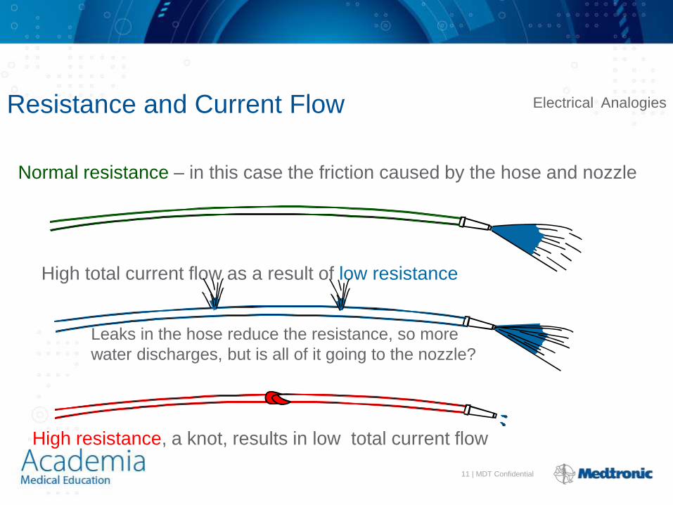
Resistance and Current Flow
Normal resistance – in this case the friction caused by the hose and nozzle
Leaks in the hose reduce the resistance, so more
water discharges, but is all of it going to the nozzle?
High resistance, a knot, results in low total current flow
High total current flow as a result of low resistance
Electrical Analogies
12 | MDT Confidential
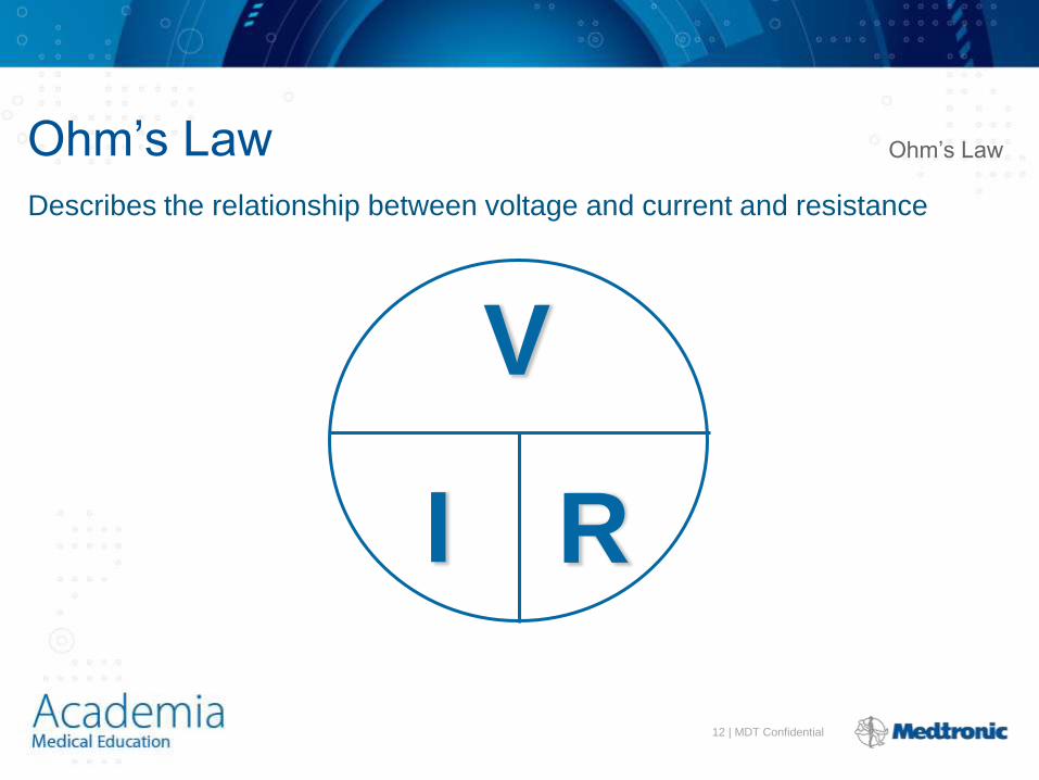
Ohm’s Law
V
I R
Describes the relationship between voltage and current and resistance
Ohm’s Law
13 | MDT Confidential
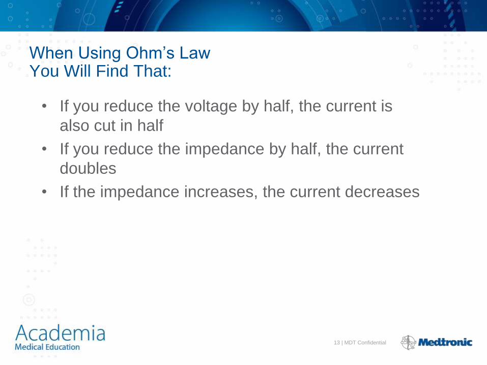
• If you reduce the voltage by half, the current is
also cut in half
• If you reduce the impedance by half, the current
doubles
• If the impedance increases, the current decreases
When Using Ohm’s Law You Will Find That:

14 | MDT Confidential
Impedance Changes Affect Pacemaker Function and Battery Longevity
• High impedance reading reduces battery current
drain and i_______ longevity
• Low impedance reading increases battery current
drain and d_______ longevity
• Impedance reading values range from 300 to 1,000
W
– High impedance leads will show impedance reading
values greater than 1,000 ohms
ncreases
ecreases
15 | MDT Confidential
Lead Impedance Values Will Change Due to:
• Insulation breaks
• Wire fractures

16 | MDT Confidential
An Insulation Break Around the Lead Wire Can Cause Impedance Values to Fall
•Insulation breaks expose the wire to body fluids which have a low resistance and cause impedance values to fall
•Current drains through the insulation break into the body which depletes the battery
•An insulation break can cause impedance values to fall below 300 W
Insulation break
Decreased resistance

17 | MDT Confidential
Insulation Break
18 | MDT Confidential
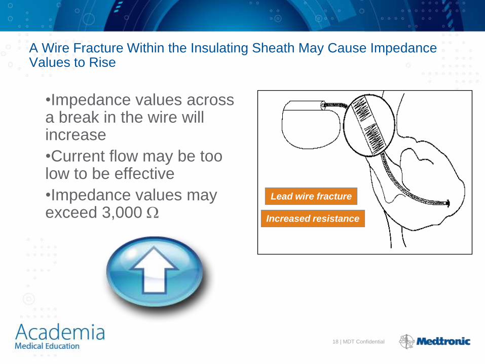
A Wire Fracture Within the Insulating Sheath May Cause Impedance Values to Rise
•Impedance values across a break in the wire will increase
•Current flow may be too low to be effective
•Impedance values may exceed 3,000 W
Lead wire fracture
Increased resistance
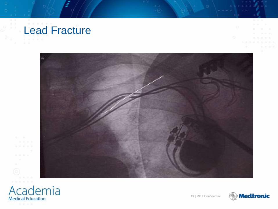
19 | MDT Confidential
Lead Fracture

20 | MDT Confidential
PACING

21 | MDT Confidential
Stimulation Threshold • The m_____ _______ ________ needed to c_________ capture the heart
outside of the heart’s refractory period
Capture Non-Capture
inimum electrical stimulus onsistantly

22 | MDT Confidential
• A function of:
– Amplitude (Voltage) - the strength of the impulse:
• The amplitude of the impulse must be large enough to
cause depolarization ( i.e., to “capture” the heart)
• The amplitude of the impulse must be sufficient to provide
an appropriate pacing safety margin
– Pulse width - the duration of the current flow expressed in
ms
• The pulse width must be long enough for depolarization to
disperse to the surrounding tissue
Myocardial Capture

23 | MDT Confidential
The Strength-Duration Curve
• The strength-duration
curve illustrates the
relationship of amplitude
and pulse width
– Any combination of pulse
width and voltage on or
above
the curve will result
in capture
Pulse Width
.50
1.0
1.5
2.0
.25 V
olts
0.5 1.0 1.5
Capture
No - Capture
24 | MDT Confidential
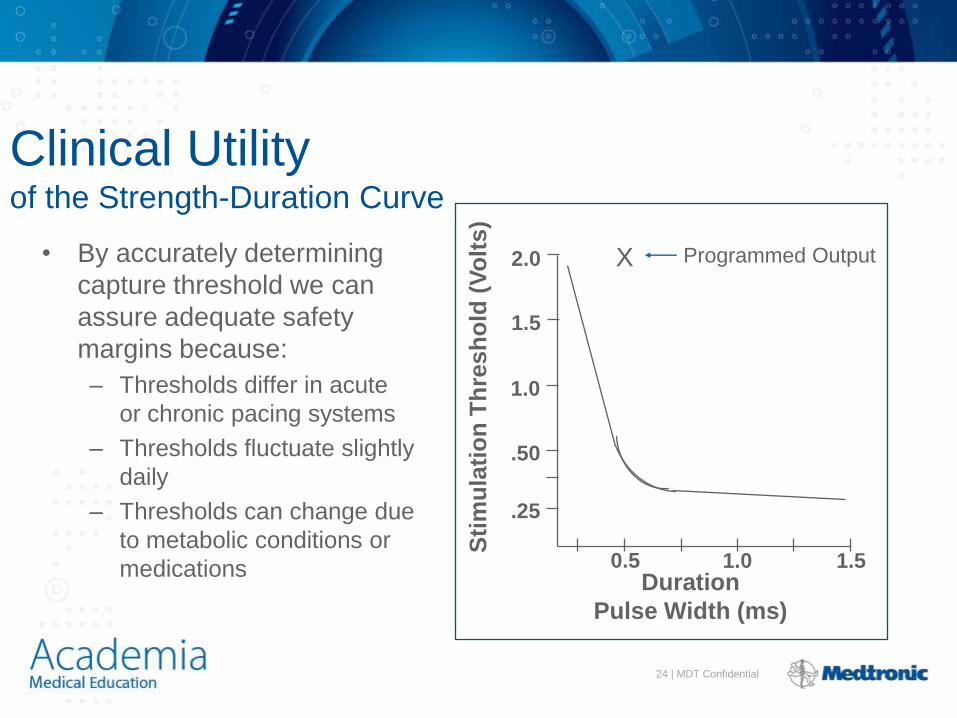
Clinical Utility of the Strength-Duration Curve
• By accurately determining
capture threshold we can
assure adequate safety
margins because:
– Thresholds differ in acute
or chronic pacing systems
– Thresholds fluctuate slightly
daily
– Thresholds can change due
to metabolic conditions or
medications 0.5 1.0 1.5 Duration
Pulse Width (ms)
.50
1.0
1.5
2.0
.25
Sti
mu
lati
on
Th
resh
old
(V
olt
s)
X Programmed Output

25 | MDT Confidential
Effect of lead design on capture
• Lead maturation
– Fibrotic “capsule” develops around the electrode following
lead implantation
– May gradually raise threshold
– Usually no measurable effect on Impedance

26 | MDT Confidential
Steroid Eluting Leads
• Steroid eluting leads
reduce the inflammatory
process
– Exhibit little to no acute
stimulation threshold
peaking
– Leads maintain low
chronic thresholds
Silicone rubber plug
containing steroid
Tines for
stable
fixation
Porous, platinized tip
for steroid elution
27 | MDT Confidential
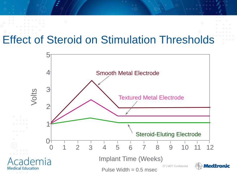
Effect of Steroid on Stimulation Thresholds
Pulse Width = 0.5 msec
0 3 6
Implant Time (Weeks)
Textured Metal Electrode
Smooth Metal Electrode
1
2
3
4
5
Steroid-Eluting Electrode
0 1 2 4 5 7 8 9 10 11 12
Volts
28 | MDT Confidential
Capture Hysteresis (The Wedensky Effect)
• The threshold measured when
decreasing voltage is less than the
threshold measured when increasing
voltage (from a sub threshold voltage)

29 | MDT Confidential
SENSING

30 | MDT Confidential
3
0
Pacemaker Sensing
• Refers to the ability of the pacemaker to “see”
signals
– Expressed in millivolts (mV)
• The millivolts (mV) refers to the size of the signal
the pacemaker is able to “see”
0.5 mV signal
2.0 mV signal
31 | MDT Confidential
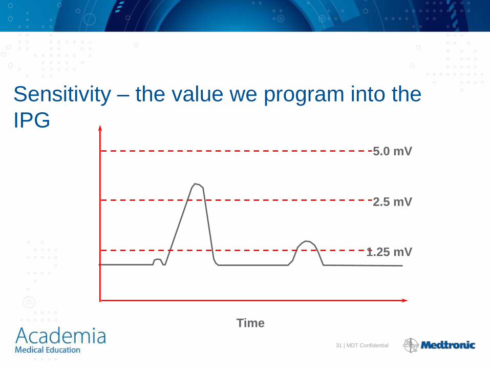
Sensitivity – the value we program into the
IPG
Time
5.0 mV
2.5 mV
1.25 mV

32 | MDT Confidential
Sensing Amplifiers/Filters • Accurate sensing requires that extraneous signals are
filtered out – Because whatever a pacemaker senses is by definition a P-
or an R-wave
– Sensing amplifiers use filters that allow appropriate sensing of P waves and R waves and reject inappropriate signals
• Unwanted signals most commonly sensed are:
– T waves (which the pacemaker defines as an R-wave)
– Far-field events (R waves sensed by the atrial channel, which the Pacemaker thinks are P-waves)
– Skeletal muscle myopotentials (e.g., from the pectoral muscle etc. which the pacemaker may think is either P- or R-waves)
– Signals from the pacemaker – eg. a ventricular pacing spike sensed on the atrial channel “crosstalk”

33 | MDT Confidential
Pacemaker sensing

34 | MDT Confidential
POLARIZATION
35 | MDT Confidential
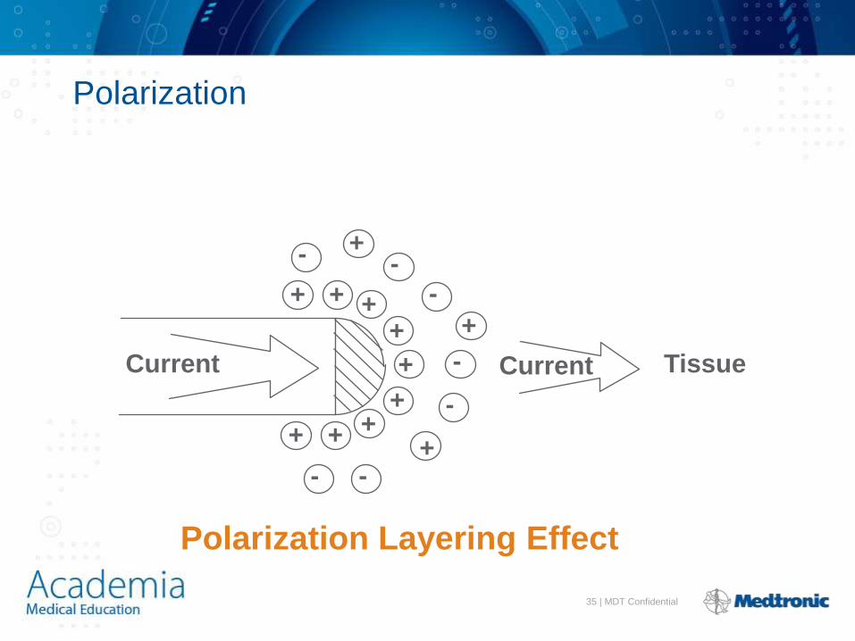
Polarization
Current Current Tissue
- + -
+
+
+ + + -
+
-
- + + + +
+ - -
Polarization Layering Effect

36 | MDT Confidential
ICD PHYSICS

37 | MDT Confidential
ICD Battery Design
• Lithium/Silver Vanadium Oxide
• Anode: Lithium
• Cathode: Silver Vanadium Oxide
• Electrically Insulated via Porous separator
• Porous Separator allows ions Flow.
• High Power to Achieve Short Charge time, High
surface area

38 | MDT Confidential
ICD Sensing
39 | MDT Confidential
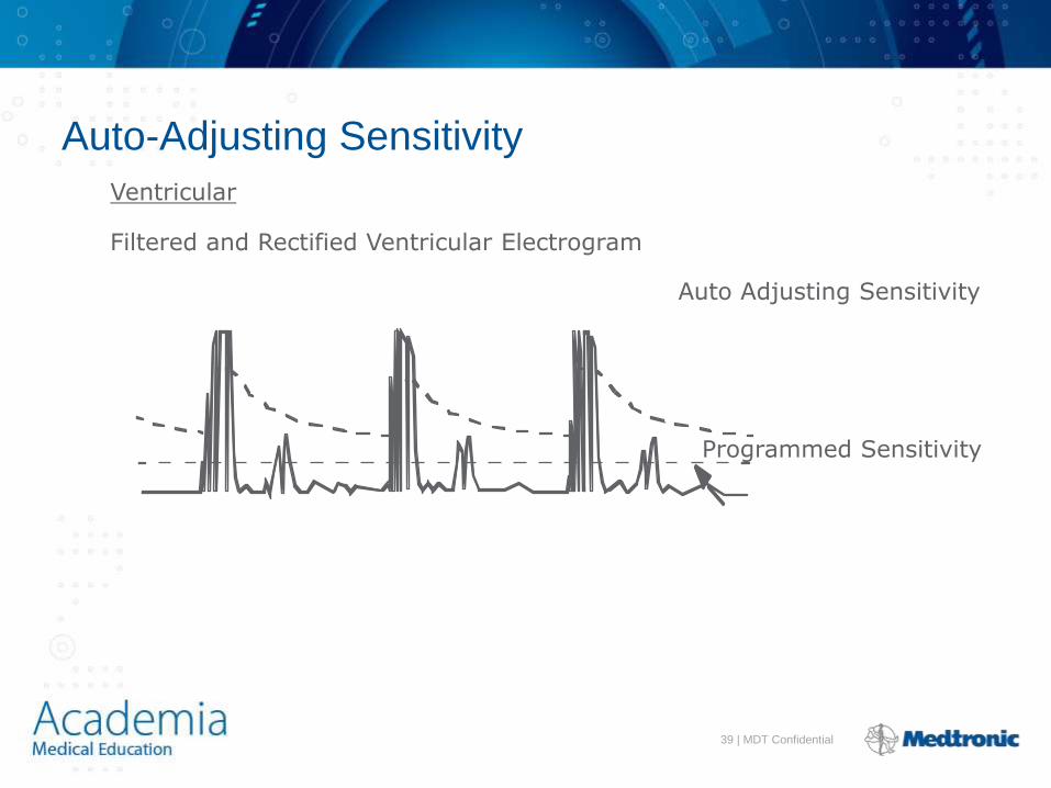
Auto-Adjusting Sensitivity
Ventricular
Filtered and Rectified Ventricular Electrogram
Auto Adjusting Sensitivity
Programmed Sensitivity

40 | MDT Confidential
Atrial
Filtered and Rectified Atrial Electrogram
Auto Adjusting Sensitivity
Programmed Sensitivity
Auto-Adjusting Sensitivity
41 | MDT Confidential
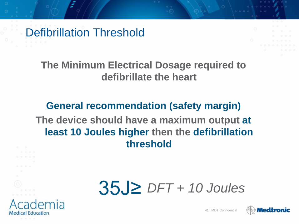
DFT + 10 Joules
Defibrillation Threshold
The Minimum Electrical Dosage required to
defibrillate the heart
General recommendation (safety margin)
The device should have a maximum output at
least 10 Joules higher then the defibrillation
threshold
35J≥
42 | MDT Confidential
Probability and defibrillation
Pacing is an all or none phenomenon At a particular pulse amplitude and duration you either capture myocardium every time or you don’t
Concept of threshold
Defibrillation is a probabilistic phenomenon No energy is guaranteed to successfully defibrillate every time

43 | MDT Confidential
Capture No capture
Pacing
44 | MDT Confidential
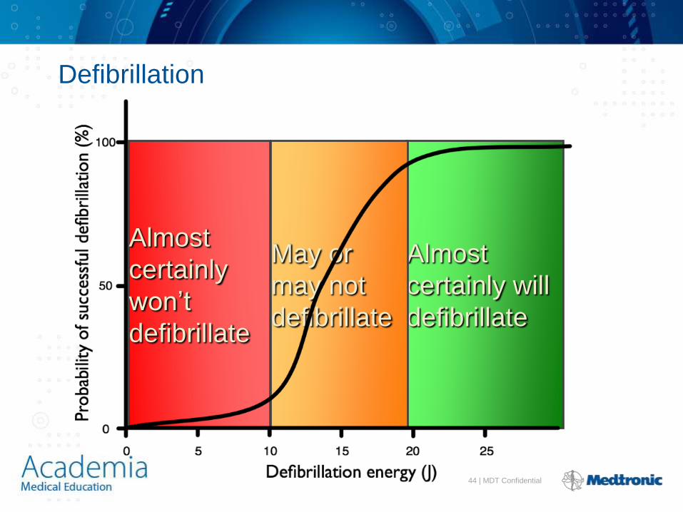
Almost
certainly will
defibrillate
Almost
certainly
won’t
defibrillate
May or
may not
defibrillate
Defibrillation
45 | MDT Confidential
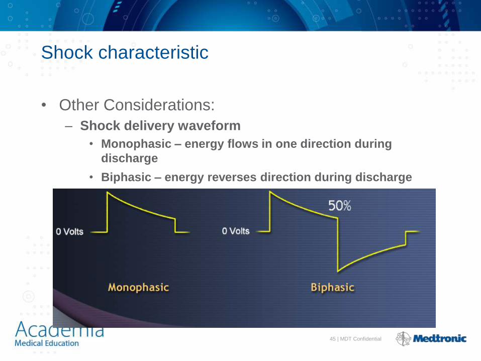
Shock characteristic
• Other Considerations:
– Shock delivery waveform
• Monophasic – energy flows in one direction during
discharge
• Biphasic – energy reverses direction during discharge

46 | MDT Confidential
Biphasic Shock
• Lower defibrillation thresholds
• Higher implant success rates
• Reduced short-term myocardial injury
• Faster return to sinus rhythm post-shock

47 | MDT Confidential
Shock Vectors
• HVA / HVX to HVB or
• HVB to HVA / HVX
A A
B
X
B

48 | MDT Confidential
Tissue Impedance
ICDs have a
capacitor system
which generates a
voltage between
the can and the coil
ΔV
49 | MDT Confidential
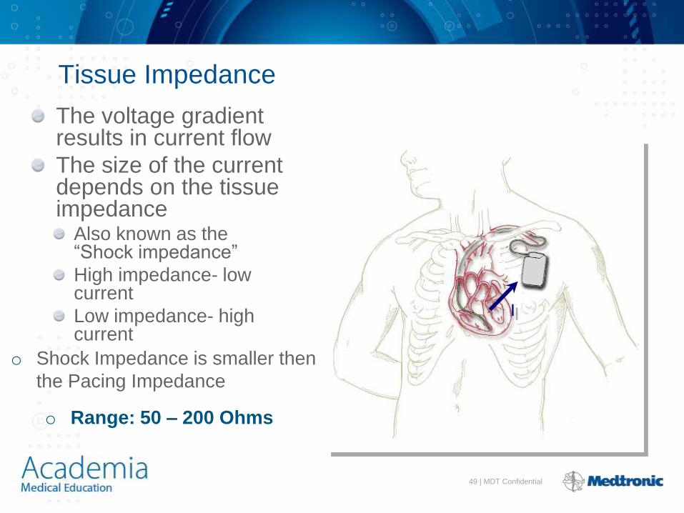
Tissue Impedance
The voltage gradient results in current flow
The size of the current depends on the tissue impedance
Also known as the “Shock impedance”
High impedance- low current
Low impedance- high current
I
o Shock Impedance is smaller then
the Pacing Impedance
o Range: 50 – 200 Ohms

50 | MDT Confidential
Tissue Impedance
High impedance will
reduce the overall
current and may prevent
successful defibrillation-
e.g.
LV dilatation
Pneumothorax I

51 | MDT Confidential
Tissue Impedance
Additional elements in the circuit can reduce the overall impedance and increase current flow
SVC coil
SQ array
Epicardial patch
Hence DFT can be lowered
I

52 | MDT Confidential
Current shunting
Additional elements in the circuit may direct current away from the heart
Impedance may be low and current high but energy never gets to myocardium
For example SVC coil in RA
Retained pacing wires/ stylets
I

53 | MDT Confidential
Thank You
• Any Questions