Embed Size (px)
Citation preview

HistoryThe original QFH was made from 10mm copper tubing only because I had some left over from mycaravan renovations. This proved to be false economy, as just the 10mm elbows and tee cost more than allthe the material for the 15mm (1/2 inch) job! The original 10mm (3/8 inch) version was tested in the loftand I immediately noticed a huge improvement over my crossed dipole. Over a period of about 2 weekstesting I was convinced that the 10mm design was almost perfect except for the odd null here and there. Ithen checked all the calculations, and made slight changes to the dimensions of both loops and balun. Aftertrying various types of balun, I decided to stick with the trifilar wound version.
Final designI then made up the 15mm (1/2 inch) version of the antenna and installed it on my chimney stack about 45feet from ground level. This extended my horizon considerably in all directions. I was receiving clearsignals from elevations down to 0 degrees from the South. However, noise appeared in the north earlierthan I would have expected. and I noticed that the QFH was leaning slightly to the South.Was the QFH directional, I wondered? If so, it was back to the drawing board. I tried tilting the QFHnorth and checked the results. The South part of the pass increased in noise and the North part becameclear. This result not being what I expected, it was up with the ladders again, and all dimensions were re-checked. Everything appeared to be correct. This phenomenon perplexed me for a considerable time, soI decided to make further changes to the loop dimensions. By the time Mark 5 came around and Irepeated the tilt test, I found that tilting made no difference to signal strength, so I installed it vertically andthen Eureka!
Other experiments carried out included the use of different types of cable. I found in my case that 17metres (18.6 yard) of RG 059 straight from the QFH connecting block (no preamp) directly into myreceiver gave the best results.
A WarningIf you are not going to use a preamp, but you have been feeding DC down the coaxial cable to power apreamp, then beware; the QFH is dead short to DC. You may need to disable the 12 volt feed eithervia switch or some other means.
Some observations At this point you will probably have seen pictures of the PHQFH, the version described here is madefrom 15mm (1/2 inch) copper tube. there have been suggestions made that perhaps a model made from22mm (7/8 inch) copper tube would be more suited to the centre resonant frequency of 137.50, but Iwould need prove that it would perform better than the 15mm version. Let’s face it, it can be quite achore bending even 15mm copper pipe, so unless you are another Mr Universe or you are prepared toanneal the 22mm tube I would stick to the 15mm version!
A Note from Judd Jensen: The diameter of the copper pipe has nothing to do with the resonantfrequency of the antenna. Changing the diameter changes the resonant frequency only a little. Moreimportantly, it changes the impedance of the antenna. We have made many loops with different diam-eters and, for example, an 8 mm pipe diameter antenna shows an impedance of about 21 ohm, whereasa 15 mm antenna is about 30 ohms impedance . Our results , how and why will be published in the nextRIG.With regards : Ruud Jansen PA0ROJ, Chairman of the Dutch workgroup KUNSTMANEN.
The PHQFH Quadrifilar Helix Antenna.Construction manual

Tools and material requirements
Tools1) Bending spring for 15mm copper pipe, 1metre long (or for piping you are using in your country)2) Joiners Vise (flat table mounted vise), Black & Decker Workmate, or similar3) Propane torch, gas supply.4) Solder, and soldering flux paste. Rosin core preferred5) Power or hand Drill with 4mm (5/32) drill6) Tapered round file, 15mm mid diameter or deburring tool on pipe cutter.7) Fine grain sandpaper for cleaning copper oxidisation8) Pipe cutter or hacksaw9) Tape measure in mm
Notes for those who don’t live in the United Kingdom
Most of the components specified here, such as the copper piping, elbows, and T-piecesare available worldwide. However, much of the time the commonly used pipe diametersvary from country to country. The only advice I can give is to make any substitutions asclose as possible in physical dimensions and electrical specification to the original speci-fied. Bear in mind that radical changes in pipe diameter mean radical changes in antennaimpedance, so try and get as close to the 15mm pipe diameter as possible. Where elbowshave different seating dimensions, you will have to recalculate overall dimensions fromthe 8.5mm assumed in this article. Improvise!!
AcknowledgementsProject creator Paul HayesOriginal QHA design : Bob Thorpe G4UNUAdobe Acrobat PDF layout using Pagemaker 6.5 & Acrobat distiller Angus Anderson ZR6UM
My solicitor (The other alf) has just pointed out to me that although I am freely offering practical adviceI should also mention obvious safety requirements. I am a member of RoSPA ( Gold advanced Driver)and I should mention general safety rules but I would hope that anyone undertaking this project willseriously consider the safety aspects involved whilst using Blowlamps, Chemicals etc, Please readinstructions carefully.
Please note that I will NOT be held responsible for any injury or damage sustainedwhilst attempting to make the PHQFH.
Hardware1) Two lengths of three metre long 15mm copper tubing, OR
Three lengths of two metre long 15mm copper tubing.2) Ten 15mm endfeed elbows, these are cheaper than ‘Yorkshire’ type.
If you do use the ‘Yorkshire’ type, allow for this when marking lengths. All my measurementsare for the endfeed type. You can also use compression and chrome plated piping if you fancy.
3) One 15mm “T” piece4) One 22mm to 15mm copper reducer.5) 22mm plastic waste connector6) 150mm long 22mm waste pipe.
10) Wooden template: One circle at 340mm Radius (13 3/8 inch) for small loop and one circle at363mm Radius (14 5/16 inch) for large loop. You can make both from the same piece becauseyou only need half circles.

And Now for the best Bit!!
I will assume you are using end feed elbows and aT piece, for which we will allow 8.5mm per joint.
Short Loop:Cut two one metre lengths of 15mm copper tubing,and mark with insulation tape or permanent markerat 752mm. This leaves a good bit at either end forgripping and helps to get the bends smoother. Cleanthe burrs from the ends of the piping, I use a roundfile because I find this easier and better than the de-burring tool that usually comes with the cutter. Don’tskimp on this bit otherwise you will have problemslater.Cut two pieces of 15mm copper tubing at 343mm.There’s no need to de-burr these.
Large Loop:Cut two one metre lengths of 15mm copper tubing,and mark with insulation tape or permanent markerpen at 804mm. De-burr as above. Cut two piecesof 15mm copper tubing at 175mm and one at367mm. There’s no need to de-burr these.
Assembly NOTE:Ensure you purchase the correct size 22mm to 15mmreducer. There are at least two different types. Youneed the one that is 22mm outside diameter {FIG1}. If using self cleaning flux then flux one end ofeach of the two 175mm lengths of tubing and solderto the ‘T’ piece joints. This should give you a totallength of 367mm to match the other pipe length youcut. I find it easier to do this first rather than cuttingpipes after the loops are soldered together. {FIG2}.
Bending the large loopNow for the bending: We will start with the largeloop just to get you in ‘bending mode’. Take one804mm length of pipe. Sit on a bench or similar, andmake yourself comfortable. Insert the bending springinto the pipe until about 50mm of spring is left pro-truding. If you require more grip for removing thespring attach some sturdy string or wire to the ringat the end of the spring. Ensure you have markedthe middle of the pipe so that you don’t bend be-yond the length of the spring. Start by gripping thepipe with one hand at the end of the pipe {FIG 3}(this is on the left for me because I am a ‘lefty’).
Figure 1
Figure 2
Figure 3
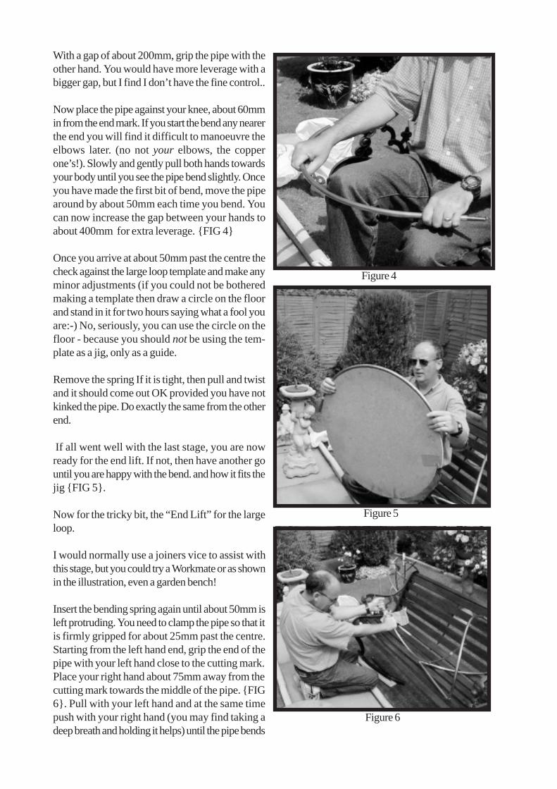
With a gap of about 200mm, grip the pipe with theother hand. You would have more leverage with abigger gap, but I find I don’t have the fine control..
Now place the pipe against your knee, about 60mmin from the end mark. If you start the bend any nearerthe end you will find it difficult to manoeuvre theelbows later. (no not your elbows, the copperone’s!). Slowly and gently pull both hands towardsyour body until you see the pipe bend slightly. Onceyou have made the first bit of bend, move the pipearound by about 50mm each time you bend. Youcan now increase the gap between your hands toabout 400mm for extra leverage. {FIG 4}
Once you arrive at about 50mm past the centre thecheck against the large loop template and make anyminor adjustments (if you could not be botheredmaking a template then draw a circle on the floorand stand in it for two hours saying what a fool youare:-) No, seriously, you can use the circle on thefloor - because you should not be using the tem-plate as a jig, only as a guide.
Remove the spring If it is tight, then pull and twistand it should come out OK provided you have notkinked the pipe. Do exactly the same from the otherend.
If all went well with the last stage, you are nowready for the end lift. If not, then have another gountil you are happy with the bend. and how it fits thejig {FIG 5}.
Now for the tricky bit, the “End Lift” for the largeloop.
I would normally use a joiners vice to assist withthis stage, but you could try a Workmate or as shownin the illustration, even a garden bench!
Insert the bending spring again until about 50mm isleft protruding. You need to clamp the pipe so that itis firmly gripped for about 25mm past the centre.Starting from the left hand end, grip the end of thepipe with your left hand close to the cutting mark.Place your right hand about 75mm away from thecutting mark towards the middle of the pipe. {FIG6}. Pull with your left hand and at the same timepush with your right hand (you may find taking adeep breath and holding it helps) until the pipe bends
Figure 4
Figure 5
Figure 6

about 10mm then move your right hand a little fur-ther towards the middle of the bend and repeat.Continue until your right hand is close to the middleof the pipe.
When you complete this stage, you should haveabout 86mm of offset in the bend. If so, then re-move the spring and insert it into the other end anddo the same. Ensure you make the end lift as perinstructions otherwise your QFH may be polarizedthe wrong way when complete.
Repeat the same procedure with the 1 metre pieceof tubing that you marked for the long loop. Cut theloops to length (i.e. 804mm). If you did everythingcorrect and did not bend the pipe to close to theend, then the end of the pipe should still be a 15mmdiameter circle, and not a oval shape. If it is ovalthen you will have some problems ahead with theelbows and alignment and will have to “Circularise”the pipe again.
Safety Note!If you have not already done so, I suggest that nowyou start breathing again.
Bending the Small loopThis stage is almost identical to the last stage exceptfor a tighter bend and less end lift. The lift should beabout 80mm at each end.
SolderingNow for the burnt fingers. We will do the long loopfirst because this is probably the hardest. Take the367mm length of copper tubing and brush some fluxon each end for about 15mm.
Fasten the tubing in a vice close to the top (if youare using a workmate then you will need to clamp itwith packing pieces). Place 15mm elbows on eachend, the left one leaning away from you and the rightone leaning towards you. {FIG 7}
Take one long loop clean and flux ends fit into leftelbow with loop facing away from you then cleanflux other long loop and fit into right elbow loop fac-ing towards you, then fit elbows to the other ends.{FIG 8} Now clean and flux the other 367mm lengthof copper tubing and fit at the top of the loops. {FIG9}
Figure 7
Figure 8
Figure 9

Notice all the short pieces of copper pipe, I havegot bags of them, if any one has any uses for themthen let me know Now for the soldering. I bet youwondered what you needed the bucket of water fordidn’t you? Well now you know. For Safety in caseyou get carried away with the blowlamp, or in mycase, get distracted and set fire to my shirt! As forthe apple, you will just have to wait.
Remember we are working on the long loop, theone with the pre soldered “T” connector. I wouldsuggest you solder the top of the loop first, so clampthe bottom of the loop in the vice. Using your blowlamp, warm up one of the top elbows (in my case Istart with the top left only because I am left handed).
Keep the blowlamp moving slowly back and forthto evenly heat the joints. Then move the flame away,but be wary where you are pointing it. Place thesolder next to the join between the elbow and thepipe. If the solder doesn’t melt and flow into thejoint, then move the solder away and continue heat-ing the joint. Try again until the solder flows.Repeatthe procedure with the other joint (the right one inmy case).
Let it cool a little, then place the top of the loop inthe vice with the “T” pointing up. You will need toensure that the “T” is vertical with the loop beforeyou solder it. At this point don’t worry to much ifthe loop top and bottom pipes do not seem to beparallel, as you can twist them later. {FIG 10}
The short loop procedure is the same as the longloop, only this time we are not using a “T” piece,and so I will leave you to get on with it.
Checking dimensionsThe illustrations should help here
Check that the top and bottom pipes are parallel.{FIG 11}.
Check the length of the loop (in this example, thelarge loop {FIG 12})
Figure 10
Figure 11
Figure 12

FIG 13 shows how to twist the loop to correct di-mensions.
Marking and cutting the top pipe for elbows(large loop) Referring to FIG 14, cut 22mm fromthe middle and save this bit for later. Repeat thiswith the small loop
Connecting the loopsYou will need a 85mm length of 22mm plastic 2 over-flow pipe. Mark and drill a 15mm hole, 15mm infrom the end. Now mark and drill a 17mm hole at90 degrees from the 15mm hole, at 50mm from sameend, {FIG 15}
If you had the presence of mind to make this at thebeginning then you only need to cut a split to the17mm hole. If not then cut splits at both ends toallow it to go over the copper pipe. If you did pre-pare it earlier, then you should have inserted the smallloop pipe through the 15mm hole before you sol-dered the loop up. Don’t ask how many times I haveforgotten. It reminds me of the old molded mainsplugs where you had to insert the flex before con-necting!. I bet if you are honest with youtselves, youprobably did the same and could not be botheredundoing the connection so you cut a split in the plugtop! I know I am waffling again but what do youwant for nowt?
Figure 13
Figure 14
Please note how the quality of the photos has sud-denly deteriorated. My photographer took a break-he said I work him too hard..
Figure 15

Fit the 85mm spacer and then solder the top elbows,ensuring the large loop connects to the small loop tothe left {FIG 16}.
Take a look at the QFH bottom complete assembly{FIG 17} To complete the bottom, saw a 22mmoverflow straight connector in half, clean any burrsfrom inside and place it over the 15mm to 22mmreducer, trapping the 85mm spacer.
Then take a complete 22mm overflow straight con-nector and tap this on until the first piece is home.Remember the straight connectors have a taperedfit, so it will get tighter the further you knock it on.
Drill 4mm holes in the top elbows, then fit the balun.Don’t use a spacer on top of the loops between thebalun and the elbows, because the nuts have to tightenonto the copper to make a good connection. Don’tforget to seal the complete balun assembly and nutsafter connecting the coax.Don’t waste money on expensive low loss cable,RG59 or RG 58 is as good as any.
Final notesWell, that’s it.I may do a trouble shooting guide but I am taking a short break for now. How is everybody getting on?I have not had much construction feedback, so I can assume either nobody is attempting it, or the one’sthat are built are doing ok?
Any constructive comments will be welcome, I will go over everything when I complete it.
Bad news; I noticed my wife Anne has bought a gallon tin of paint and is talking about new Kitchen Units.Never mind, I may get my son Neal to practice his DIY skills! or perhaps I may have a funny do. Itworked! They are both doing the decorating so I can carry on with my DIY guide. I may need to take abreak now and again whilst they paint around my computer :-)))
It’s been nice working with you all. Don’t be afraid to continueexperimenting and trying new ideas- some of the best ideashave come through mistakes. If you would like to see what thefinished product looks like, look to the right.
Then you might understand why having green fingers, good pot-ting compost and a relaxing environment helps. Please don’tover water the QFH.
Now all your suspicions have been proved correct, yes I ammad, but I am happy!
Figure 16
Figure 17


![Design of Ionofree Micro Strip Quad Helix Antenna for ... · antenna, bifilar helices antenna, microstrip antenna, quadrafilar helix antenna. ... Helical antenna [1],[2] is broadband](https://img.pdfslide.us/doc/110x75/5b9506e809d3f2ea5c8b5a04/design-of-ionofree-micro-strip-quad-helix-antenna-for-antenna-bifilar-helices.jpg)