Embed Size (px)
Citation preview

The PhaetonChassis
Design and function
Self-Study Programme 277
Service.

2
S277_033
In top form, the Phaeton chassis fulfils even the most challenging demands on comfort and driving dynamics.Through its components, including
- Speed dependent power-assisted steering, - Four-link front suspension, - Trapezoidal wishbone rear suspension and- ESP with braking assistant,
it achieves an important contribution towards active vehicle safety.
NEW CautionNote
The self-study programme presents the design and operation of new developments!Contents will not be updated.
Current testing, adjustment and repair instructions may be found in the appropriateservice material.

3
At a Glance
Introduction . . . . . . . . . . . . . . . . . . . . . . . . . . . . . . . . . . .4
Front axle . . . . . . . . . . . . . . . . . . . . . . . . . . . . . . . . . . . . 6
Rear axle . . . . . . . . . . . . . . . . . . . . . . . . . . . . . . . . . . . . 12
Measurement. . . . . . . . . . . . . . . . . . . . . . . . . . . . . . . . . 16
Steering system . . . . . . . . . . . . . . . . . . . . . . . . . . . . . . . 18
Brake system . . . . . . . . . . . . . . . . . . . . . . . . . . . . . . . . .32
Wheels and tyres. . . . . . . . . . . . . . . . . . . . . . . . . . . . . .46
Tyre pressure monitor . . . . . . . . . . . . . . . . . . . . . . . . . .48
Check your Knowledge . . . . . . . . . . . . . . . . . . . . . . . .59

4
Introduction
The chassis
● Independent wheel suspension front andrear
● Four-link front suspension with 1628 mm track width
● Trapezoidal wishbone rearsuspension with 1612 mmtrack width
● Front and rear anti-roll bars
● 4-corner air suspension with regulated damping
S277_002

5
● Ventilated disc brakes
● Braking assistant
● Speed dependent power-assisted steering
● Electronic Stability Programme, Bosch 5.7
● Foot parking brake
● Tyre pressure monitor, optional

6
Front axle
The front axle
S277_129
The Phaeton's front axle is equipped with four-link suspension. The multitude of guide elements produces the following advantages:
- Complete isolation of drive forces from the steering- High steering precision through optimised positioning of the pivot axis- Good driving comfort- Exceptional anti-squat and anti-dive performance

7
Bearing block aluminium cast part
The upper suspension links(front and rear)
aluminium forged parts
Bearing linksteel forged part
Wheel bearing housingsteel cast part
Guide linkaluminium forged part
Anti-roll barsteel
Subframe made ofhydroformed steel
S277_010
The component overview

8
Front axle
The bolted wheel bearing
The anti-roll bar
The wheel bearings are not pressed into the wheel bearing housing as was the practice up to now, but bolted directly to the wheel bearing housing as a unit (bearing and bearing housing).
This enables the wheel bearing to be installed without removing the pivot bearing or jointed shaft.
Depending on the engine, the Phaeton has either a solid anti-roll bar of 35 mm diameter or a tubular anti-roll bar of 35 mm diameter and 6 mm wall thickness.
The intermediate rubber bearings and aluminium pipe clamps are vulcanised on in this design and cannot be replaced.
This support arrangement, which was designed to have radially rigid and rotationally flexible characteristics, prevents noise and wear.
S277_044
S277_025
Wheel hub Wheel bearing housing
Bolted connection
Bolted connection
Rubber bearing with aluminium pipe clamps
Wheel bearing

9
The connection of the air suspension strut to the suspension link
The subframe
The high-pressure formed subframe of tubular steel is bolted to the body using rubber-metal bearings. This flexible connection keeps the body free of forces and impacts that the chassis introduces.
The additional bolted brace ensures ample transverse rigidity.
The air suspension strut is attached to the bearing link with a rubber-metal bearing.
S277_026
S277_037
Brace
Air suspension strut
Bearing link

10
Front axle
The virtual steering axis
With the four-link front suspension, the steering axis does not run through the upper and lower joints on the wheel bearing housing as with previously familiar front axle designs. Instead it runs through the intersection points formed by extrapolating the connection lines of the two upper and two lower suspension link joints respectively.
Thus, the suspension link axis is in free space and does not change position at full steering lock. This is why we refer to it as the virtual steering axis.
This arrangement enables the steering axis to be placed close to the wheel centre plane. This has a positive effect especially on the scrub radius and the road feedback lever arm, and thus produces advantages in driving behaviour.
1-4 Directions of the suspension links
R Wheel centre point
A Wheel contact point
n Trail
nv Castor offset
p Scrub radius
a Road feedback lever arm
Point AS = Piercing point of the
steering axis on the
roadway
S277_029

11
The full steering lock positions
Link position for left curve
Link position for straight driving
Link position for right curve
This axle design allows the virtual steering axis, around which the wheel moves and whose position determines the castor angle and the steering swivel inclination, to be shifted much further out. By optimising the axle geometry, it is possible to completely isolate torque steer effects on the steering.
Since the wheels are located using four ball sockets on the respective transverse links, the pivot axis can run approximately in the wheel centre independently of construction space requirements. The pivot axis is designed to change position according to the steering movements.
The defined movement of the axis when steering reduces the space requirements in comparison to conventional axle systems with fixed space steering axes.
The virtual steering axis changes position depending on the steering movements.
S277_070
S277_040
S277_072

12
Rear axle
In the Phaeton, the rear axle is designed with trapezoidal (unequal length) wishbone suspension. All wheel location elements are mounted to a subframe that is rigid in bending, torsion and warping.
This is connected to the body using large-dimensioned rubber bearings. This type of structure achieves exact wheel location and good ride.
The rear axle, front wheel drive
The wheel hub
Instead of the bolted constant velocity (CV) joint pivot, the wheel bearing is prestressed with a stub axle.
The rear axle for front wheel drive vehicles is equivalent to the axle for all-wheel drive vehicles. Rear axle drive and jointed shafts are not used.
S277_101
S277_046
Wheel bearing housing
Bolted connection
Bolted connection
Stub axle

13
The rear axle 4-motion
In the 4-motion version, the subframe holds the rear differential at three points. Therefore, the rear differential is doubly isolated from the body.
S277_016
14
Rear axle
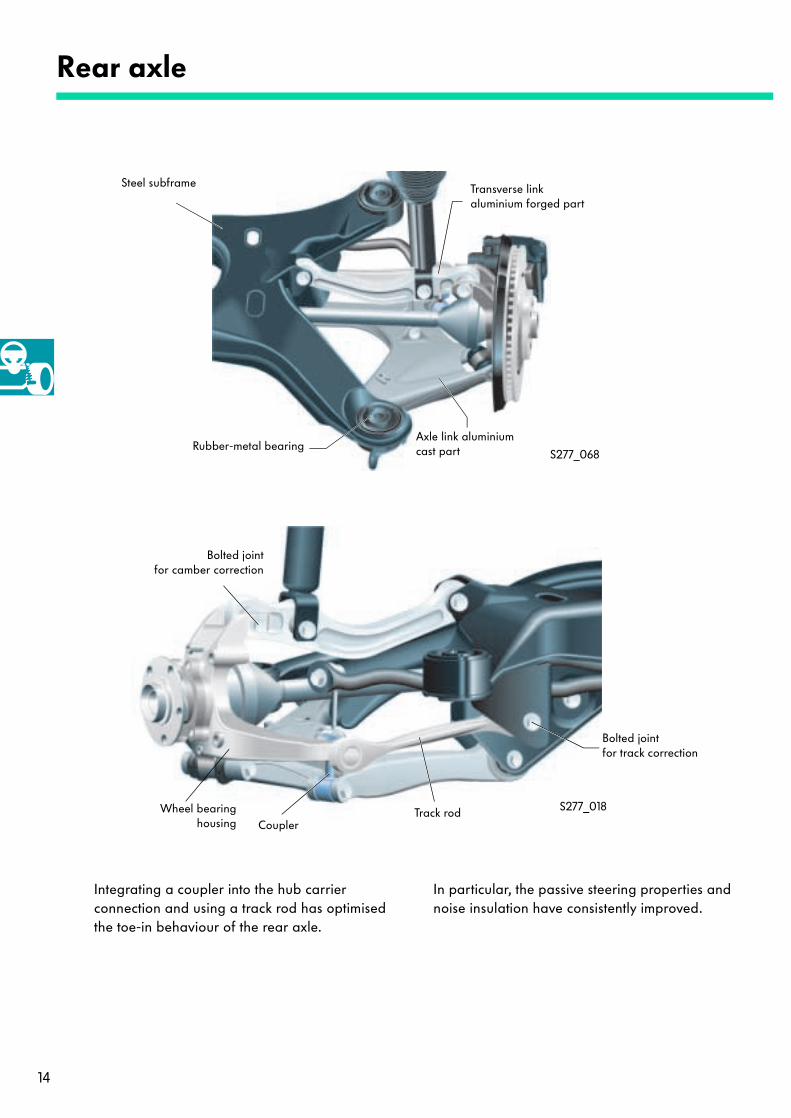
Integrating a coupler into the hub carrier connection and using a track rod has optimised the toe-in behaviour of the rear axle.
In particular, the passive steering properties and noise insulation have consistently improved.
Steel subframe
Rubber-metal bearingAxle link aluminium cast part
Transverse linkaluminium forged part
Bolted jointfor track correction
Bolted jointfor camber correction
S277_068
S277_018
CouplerTrack rodWheel bearing
housing

15
The anti-roll bar
The wheel bearing housing
An anti-roll bar made of 20 mm solid material has been installed on the rear axle. The rubber bearings are vulcanised on as in the front axle. This design is free of noise and wear.
With the rear axle, as with the front axle, the wheel bearings are bolted to the wheel bearing housing. The wheel bearings on the front and rear axles are identical in construction.
S277_031
S277_044
Wheel hubWheel bearing housing
Bolted connection
Bolted connection
Rubber bearings

16
Measurement
The particularities of measurement
The Phaeton is equipped with 4-corner air suspension as standard. Before every measurement, the level position of each suspension strut must be checked.
When measuring the vehicle, the familiar parameters, camber and toe-in, must be adjusted on the rear or front axle.
Toe-in curve diagram
Extension in mm
Compression in mm
Toe-in in degrees
-20.
-40.
-60.
-80.
-100.
-120.
-20.20. -40. -60.40.60.
20.
40.
60.
80.
100.S277_042
In addition, a toe-in value is set at the front axle when the suspension is extended. The adjustment must be made with the wheel extended by 60 mm when the vehicle is empty.
Adjusting the toe-in curve with the wheel in an extended state sets the toe-in curve for driving stability.

17
The following steps are important when performing the front-end alignment:
- Setting the basic toe-in with an empty vehicle by changing the length of the track rod- Setting the inclination of the toe-in curve by changing the height of the outer
track rod joint
S277_020
S277_021
h
A
h = Adjustment range for the toe-in curve A = Adjustment option for independent toe-in

18
Steering system
The steering system
S277_093
Overview
The steering column
The Phaeton is equipped with an adjustable steering column. The travel range is 50 mm in the axial direction and 40 mm in the vertical direction. The steering column is available with either manual or electric adjustment.
S277_083

19
With manual adjustment, eight steel discs lock the steering column in place on each side of the steering tube using a clamping mechanism. Here there are four discs for axial adjustment and four discs for vertical adjustment per side.
The advantage: infinite adjustment with high holding forces.
S277_066
Adjustment of the steering column - mechanical adjustment
Disc pack
Steering tube
unclamped clamped
Adjustment of the steering column - electrical adjustment
The electric steering column is essentially the same in concept as the manually adjustable steering column with reference to kinematics, adjustment field, installation space, connection and crash concept.
The electric steering column is infinitely adjustable in the axial and vertical directions and is driven by electric motors.
Console
Motorfor axial adjustment
Crash carriage
Pull tab
S277_081Spindlefor vertical adjustment

20
Steering system
Adjustment of the steering column - circuit diagram
The comfort CAN bus carries the command signal to adjust the steering column, and the control unit for driver seat/mirror position processes it.
The steering column electronics control unit interprets and reads the driver's wish from the steering column adjustment button and places the signal on the comfort CAN bus.
The control unit for driver seat/mirror position then sets the motors to the corresponding position.
Hall sensors in the adjuster motors send the return signal to the control unit for driver seat/mirror position.
S277_091
Switch for steering column adjustment
± Z, ± Y
Control unit for steering column electronics
J527
Control unit for driver seat/mirror position
J543
Steering column adjustment motor, Z
Steering column adjustment motor, Y
Steering column Z position
Steering column Y position

21
The electric steering column lock
The Phaeton uses an electric steering column lock instead of a mechanical steering lock.
The electric steering column lock is an integrated system with an electrical interface to the access and start authorisation control unit and a mechanical interface to the steering column.
When the electric motor is activated, the worm gear moves the push rod in the longitudinal direction. To lock the steering column (terminal 15, out), the inner-toothed locking collar is pushed over the conical, outer-toothed locking star until it stops. To unlock the steering column (terminal S, in), the locking collar is pulled away from the locking star.
S277_074
Locking collar Locking star
Worm gearPush rod
Motor for steeringcolumn lock, N360
Control unit with two Hall sensors
Control unit for access and start authorisation, J518
lockunlock

22
Steering system
The Servotronic
Design and function
The Phaeton is equipped with Servotronic. This hydraulic steering system, which is electronically controlled and speed dependent, is distinguished by light, comfortable steering while parking and a safe driving feel with increasing speed.
S277_049
Power-steering pump
Servotronicsolenoid
valve, N119

23
The diagram shows how the pressure changes with respect to application moment in relation to driving speed.The characteristic curve has been specifically adjusted to the vehicle character.
The Servotronic steering system is based on hydraulic steering.The hydraulic steering's modified rotary valve uses the principle of direct hydraulic reaction (feedback).Using an electro-hydraulic converter and reconfiguring the steering valve accordingly has enabled the Servotronic system to operate according to driving speed.
Application moment (Nm)
Pressure p (bar)
The Servotronic characteristic curve diagram
S277_051
120
100
80
60
40
20
0
0 2 4 6 8 10246810
120 km/h
50 km/h
0 km/h

24
Steering system
The electric control
Servotronic solenoid valve, N119
Road speed signal
15 31
The Servotronic control unit evaluates the road speed signal from the dash panel insert and converts the signal into modulated current. This actuates the N119 solenoid valve.
The N119 solenoid valve determines the hydraulic reaction at the rotary valve and thus the application moment at the steering wheel.
The speed dependent influence on the steering translates into minimum forces required for steering at still stand and low speeds.
Since the hydraulic reaction changes in relation to diving speed, the application force at the steering wheel increases with increasing speed. This gives the driver especially good contact with the roadway, allowing the driver to steer accurately.
S277_095

25
The steering system remains fully functional if the vehicle electrical system fails or other electrical faults occur. The Servotronic system then works using the mechanical forced opening of the N119 solenoid valve at maximum hydraulic reaction (fast speed characteristic curve).
Safety with the Servotronic system
The characteristic curve for control current to the solenoid valve
If the road speed signal fails while driving, the Servotronic system remains at the last given control range until the ignition is switched off. The next time the motor is started, the maximum hydraulic reaction develops, according to the fast speed characteristic curve.
S277_067
900
800
700
600
500
400
300
200
100
0
Con
vert
er c
urre
nt I
[mA
]
Tacho frequency fe [Hz]
0 20 40 60 80 100 120 140 160 180
0 20 40 60 80 100 120 140 160
Driving speed v [km/h]

26
Steering system
The rotary valve in neutral position - vehicle stationary
The familiar hydraulic pump generates the pressure that the Servotronic system requires, about 130 bar, which is transferred to the rotary valve. In the valve unit is a torsion bar, which is pinned to the rotary valve on one side and to the driving pinion and control bush on the other side. The torsion bar is responsible for centering (neutral position).
S277_053
Rotary valve
Control bush
Working cylinder,left
Working cylinder,right
Working cylinder, left
Working cylinder, right
Control bush Pressure and flowrelief valve
Rotary valve
Pin connection
Road speed signalControl unit
Torsion bar
Return
Solenoid valve forServotronic
Reactionpiston
from the pump
Torsion bar

27
The oil that the hydraulic pump supplies flows through the connection hole in the valve region and into the inflow radial channel. It then flows into the cross holes in the control bush to the inflow control channels in the rotary valve. In the valve neutral position, the oil flows via the open inflow control vanes into all axial channels in the control bush. From there it flows via the open return control vanes also into the return control channels in the rotary valve.
From these channels, the oil can flow through connections into the return chamber, and from there back to the oil reservoir. At the same time, the radial channels in the valve body and the associated tube lines connect the right and left working cylinder chambers.
S277_055
S277_057
Inflowcontrol channel
Returncontrol vane
Inflowcontrol vane
Axial channel
Inflowradial channel
Returncontrol channel
Return
from the pump
Reaction chamber
Reaction piston
Radial channel
Inflow radial channel
Radial channel
Return chamber
Right working cylinder
Left working cylinder
Control bush

28
Steering system
The rotary valve in working position, left full steering lock - driving at low speed
At left full steering lock, oil must flow to the right side of the working cylinder to assist the steering effort.
The force at the steering wheel turns the torsion bar in its elastic range, since it is pinned to the rotary valve at the top and to the control bush and driving pinion at the bottom.
The torsion bar, which narrows in the appropriate region, turns the rotary valve against the control bush.
The pressurised oil travels via the inflow control vanes, which are further open, into the associated axial channels, through the hole in the radial channel and via a tube line to the right cylinder chamber, thus hydraulically assisting the steering rack to move. The pressurised oil in the right cylinder chamber pushes the oil out of the left cylinder chamber into the return line.
If the driver releases the steering wheel, the torsion bar ensures that the rotary valve and the control bush spring back into the neutral position.
S277_059
Rotary valve
Control bush
Working cylinder, left
Working cylinder, right
Working cylinder, left
Working cylinder, right
Control bush Pressure and flowrelief valve
Rotary valve
Pin connection
Road speed signalControl unit
Torsion bar
Return
Solenoid valve forServotronic
Reactionpiston
from the pumpTorsion bar

29
The servotronic control unit evaluates the road speed signal and passes it on to the N119 solenoid valve as modulated control current.
Due to the maximum current produced in this driving situation, the N119 solenoid valve closes and prevents oil from flowing from the inflow radial channel to the reaction chamber.
A baffle ensures that the return pressure level also acts in the reaction chamber. Thus, the Servotronic rotary valve behaves as a normal rotary valve in this situation.The steering is light and can be operated with little effort since the reaction has been eliminated.
S277_061
Return
from the pump
Reaction chamber
Reaction piston
Radial channel
Inflow radial channel
Radial channel
Return chamber
Right working cylinder
Left working cylinder
Control bush
Baffle
Solenoid valve forServotronic

30
Steering system
The rotary valve in working position, right full steering lock - driving at high speed
At right full steering lock, oil must flow to the left side of the working cylinder to assist the steering effort.
The force at the steering wheel turns the torsion bar in its elastic range, since it is pinned to the rotary valve at the top and to the control bush and driving pinion at the bottom.
The torsion bar, which narrows in the appropriate region, turns the rotary valve against the control bush.
The pressurised oil travels via the inflow control vanes, which are further open, into the associated axial channels, through the hole in the radial channel and via a tube line to the left cylinder chamber, thus hydraulically assisting the steering rack to move.
The pressurised oil in the left cylinder chamber pushes the oil out of the right cylinder chamber into the return line. If the driver releases the steering wheel, the torsion bar ensures that the rotary valve and the control bush spring back into the neutral position.
S277_063
Rotary valve
Control bush
Working cylinder, left
Working cylinder, right
Working cylinder, left
Working cylinder, right
Control bush Pressure and flowrelief valve
Rotary valve
Pin connection
Road speed signalControl unitTorsion bar
Return
Solenoid valve forServotronic
Reactionpiston
from the pump
Torsion bar

31
As the speed increases, the Servotronic control unit reduces the control current to the N119 solenoid valve. With this, the N119 solenoid valve takes on a certain opening position and enables a limited oil inflow from the inflow radial channel into the reaction chamber. A baffle prevents large amounts of oil from flowing out into the return chamber, so that higher pressure develops in the reaction chamber. The increased pressure acting on the reaction piston then generates a greater pressing force on the balls guided by V-ways. These balls are located between the reaction piston and the centering piece, which is firmly joined to the control bush.
At high driving speeds, the N119 solenoid valve is completely open due to the very low or zero control current. Thus, the inflow radial channel supplies maximum pressure to the reaction system. When the driver turns the steering wheel to the right, the reaction pressure also increases corresponding to the prevailing operating pressure and pushes the reaction piston out of the reaction chamber.
During straight driving, this has a positive effect on the centering of the rotary valve, making it particularly exact. When the rotary valve pivots, the balls, which are now more highly loaded, exert additional resistance against turning of the rotary valve. Therefore, with the hydraulic reaction in this sequence of operations, the specifically determined application moment required to move the steering wheel is higher.
As soon as the reaction pressure, which is determined specifically for the vehicle, is reached, the cut-off valve opens and the oil flows out into the return chamber so that the pressure does not increase further. The application moment at the steering wheel now does not increase further, and conveys a secure driving feel through optimum contact with the roadway.
S277_065
Reaction piston
Reaction chamber
Centering piece
BallBaffle
Inflow radial channel
Solenoid valve forServotronic
Cut-off valve
Return chamber
Control bush

32
Brake system
The brake system
The Phaeton’s high performance brake system consists of newly developed front and rear wheel brakes.
Front wheel brake
Foot parking brake
Pedal cluster
ABS hydraulic unit
Dual brake servo

33
S277_006
Rear wheel brake
Brake lines
Brake cables
The brake system is fitted with the Bosch ABS System 5.7 with integrated ESP as standard. It is diagonally separated into 2 circuits. The Phaeton has large ventilated brake discs front and rear.

34
Brake system
The brake equipment (all brake parts are made of aluminium)
Engine Front Rear
V6 Ø 323 mm x 30 mm Ø 280 mm x 22 mm
V8 Ø 360 mm x 34 mm Ø 310 mm x 22 mm
V10 TDI, W12 Ø 365 mm x 34 mm Ø 335 mm x 22 mm
The wheel brakes
To satisfy demanding safety requirements and guarantee a high level of comfort, the wheel brakes have been specially designed for the Phaeton.
The front wheel brakes
A new aluminium brake calliper was developed for the Phaeton's 18" front wheel brake. This light-weight brake calliper consists of an unseparated housing in a monoblock design with 8 pistons and 4 brake pads.
This arrangement ensures optimum conditions for pressing the brake pads onto the brake disc. The brake calliper design, which has a wide reach around the friction ring, achieves a low weight combined with optimal calliper stiffness.
S277_103

S277_012
Brake disc cupmade of aluminium
Friction ringSlider
The front brake disc
The front brake disc is constructed from two parts. The friction ring is attached to the brake disc cup with sliders. The design allows the brake disc to freely expand radially. This significantly improves the thermal shock resistance, that is, it increases the life of the brake disc. At the same time, this type of connection has a favourable effect on the deformation of the friction ring under temperature loading. Thus, the noise behaviour is also improved.
A positive spin-off of this design is the weight saved by manufacturing the cup from aluminium. The specially formed cooling ribs provide a robust construction with optimal flow-through. Specially shaped rims and an air guide part guide the air stream directly to the brake disc.
The rear wheel brakes
The Phaeton's rear wheel brakes are high-performance, ventilated disc brakes. The brakes use a newly developed aluminium brake calliper. The parking brake feature is integrated into the brake calliper.
35
S277_008

36
Brake system
To retain the mechanical and hydraulic function of the brakes in this system, the increase in clearance that results from brake pad wear must be compensated by resetting.
A turning action of the resetting nut on the thread of the push bar resets the clearance increase that results from brake pad wear.
S277_108
Sloped disc
Parking brake lever
Actuating shaft
Housing
Push bar
Compressionspring
Resetting nut Spring washer Piston Brake disc
Brake pad
Automatic resetting
Actuation of the rear wheel brakes
When the driver applies the hand brake, the brake cables actuate the parking brake lever on the brake calliper. The actuating shaft turns and performs a stroke.
The mounting of the actuating shaft on three balls, which are positioned on a sloped disc, produces the stroke. The stroke movement actuates the piston which clamps the brake calliper and presses the brake pads against the brake disc.

37
The push bar is held by the compression spring; the turns of the thread between the push bar and resetting nut are engaged in this resetting sequence. The coarse-pitch thread between the push bar and resetting nut produces a turning moment on the resetting nut. The cone clutch between the resetting nut and the piston opens far enough so that the resetting nut can turn on the thread of the push bar by the amount of the increased clearance in the brake application direction. This resetting process takes places also when the brake calliper is relieved, that is, after the braking process. Thus the brake wear that occurs while braking is directly and non-incrementally reset. After the brake calliper is relieved, a clearance between the brake pads and brake disc appears (figure D).
The nominal clearance is the play between the resetting nut and push bar thread determined by tolerances (figure C).
S277_110
S277_112
S277_114
S277_116
Increased clearance
Cone clutch
Nominal clearance
Clearance
Resetting nut
Push barWhen the driver applies the brakes and hydraulic pressure develops in the brake system and brake callipers, the piston moves in the housing towards the brake disc. The resetting nut is carried in the piston by a spring washer.If the clearance increases due to brake pad wear, it is compensated in the thread between the push bar and resetting nut. The force of the compression spring on the resetting nut acts against the pressing direction of the piston. This opens the cone clutch between the resetting nut and the piston (figures A and B).

38
Brake system
The foot parking brake
For the first time, Volkswagen has introduced in the Phaeton a foot parking brake, distinguished by its low weight, minimum release force and responsive design. The pedal cluster is manufactured from aluminium alloy.
The parking brake is located in the left of the footwell above the foot rest. The parking brake is applied by pressing the pedal.
When the driver presses the foot parking brake pedal, a control cable transfers the applied force to a lever mechanism under the floor of the vehicle. Here, the force is divided over two brake cables, which operate the actuating mechanisms on the rear wheel brakes.
The parking brake is released by pulling the release lever below the light rotary switch by hand.
Control cable
Release cable
Release lever
PedalS277_109

39
The coil spring, which acts on a drum, takes on the brake locking function. The spring slides on the drum and expands due to the direction of movement. If the counter force of the brake moves the spring in the other direction, it pulls together and increases the friction between the coil spring and drum. Thus, the pedal locking action is almost completely stepless and noiseless. An additional plastic spring produces the typical click sound when the pedal is pressed.
When the driver pulls the release lever, the retainer of the release cable is drawn upwards. This expands the coil spring, or in other words, the spring becomes moveable and the pedal can return to the initial position. This principle requires low release forces.
Lock: The coil spring presses against the drum when the pedal moves in the opposing direction.
Release:The diameter of the coil spring becomes larger when the spring expands. The coil spring can move on the drum.
S277_156
S277_154S277_152
Control cable
Cable retainer
Retainer forrelease cable
Release cable
Coil spring
Expand
Drum
Coil springDrum
Pedal
Plastic spring

40
Brake system
The brake lines and brake cables
The brake line system connects the hydraulic components of the brake system. The brake lines consist of galvanised steel pipes, which have a resistant surface protection provided by the zinc plating and an additional polyamide coating.
These lines are attached to the body with plastic holders. A robust, hard outer shell is used for attachment. Injected, soft elements are used for noise insulation.
The brake cables are sheathed in polyamide and greased to prevent corrosion and reduce friction forces.
The moveable connections in the lines to the front and rear axles are brake tubes. The inner tube consists of a material that keeps water absorption into the brake fluid low. For stabilisation, this tube has several braided fibre sleeves, which are protected against external influences by CR rubber.
The lines in the engine compartment as well as those in the connection lines between the ESP unit and the brake servo are connected to plastic tubes with braided steel sheathing. The structure of these lines also reduces noise transfer from the unit during operation.
Structure of the hand brake cable
Protective shell made of polyurethane
Profile wire spiral made of bare drawn stranding wire
Lining tube made ofPolyamide
Polyamide
Wire strand made of drawn stranding wires
S277_102
The hand brake cable

41
The pedal cluster
S277_119 S277_117
Pedal cluster - manual transmission Pedal cluster - automatic transmission
The bearing block of the pedal cluster is made of aluminium alloy. It is designed to break at a specific location in the event of a crash. Thus the driver's lower legs and feet are not endangered.
To upgrade the aesthetics, additional custom covers are fitted to the pedals.

42
Brake system
The Bosch 5.7 ABS / ESP anti-lock braking system
S277_131
The Phaeton uses the Bosch 5.7 ABS system with ESP (electronic stability program) with hydraulic braking assistant.

43
The special characteristics of the Bosch 5.7 ABS system include:
- The hydraulic unit and control unit are integrated into one unit.- The G201 brake pressure sensor screws directly into the hydraulic unit.- An ESP feature without preloading is provided.- The ESP has EDL, TCS and ABS features as well as a braking assistant.- Even when the active ESP function is switched off, the vehicle remains stable in critical situations
due to the application of ESP logic (“passive” ESP).
G201 Brake pressure sensor
S277_106
Control unit with hydraulic unit
S277_104
44
Brake system
The active wheel sensor system
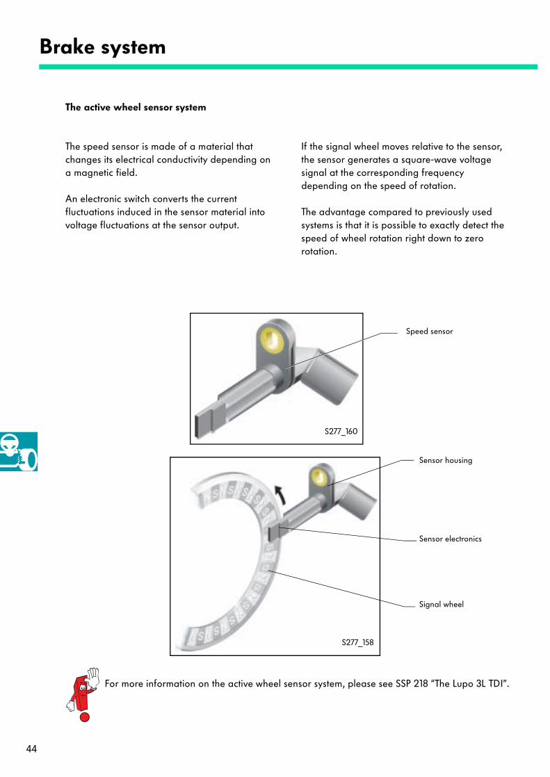
The speed sensor is made of a material that changes its electrical conductivity depending on a magnetic field.
An electronic switch converts the current fluctuations induced in the sensor material into voltage fluctuations at the sensor output.
If the signal wheel moves relative to the sensor, the sensor generates a square-wave voltage signal at the corresponding frequency depending on the speed of rotation.
The advantage compared to previously used systems is that it is possible to exactly detect the speed of wheel rotation right down to zero rotation.
Speed sensor
Signal wheel
Sensor electronics
Sensor housing
S277_160
S277_158
For more information on the active wheel sensor system, please see SSP 218 “The Lupo 3L TDI”.

45
The dual brake servo
The brake servo is an 8/9" dual brake servo with a stroke of 36 mm.The diameter of the main brake cylinder is 26.99 mm.The dual brake servo has a light-weight construction and has the following features:
- The central valves of the dual main brake cylinder guarantee the shortest application distance at the pedal combined with reliable, self-priming ESP functionality.
- The active (electrically activated) brake servo variant represents the core component for activation with automatic delay of the vehicle in ADC operation (automatic distance control) and guarantees regulated, automatic delay.
Vehicles with ADC have an active brake servo.For more information, please see SSP 276 “Automatic distance control”.
Displacement sensor, only in vehicles with ADC
Pressure sensor,only in vehicles with ADC
Connection for release switch,only in vehicles with ADC S277_105

46
Wheels and tyres
The wheels and tyres
The Phaeton sets standards in comfort and driving dynamics. Different wheel-tyre combinations are available with the Phaeton.
Vehicles with V6 petrol engines are equipped with cast aluminium wheels with dimensions 7½ J 16 ET40 and 235/60R16 tyres as standard.
Vehicles with W12 petrol engines have 18" cast aluminium wheels with dimensions 7½ J 18 ET40 and 235/50R18 tyres.
One-piece cast aluminium hollow spoke wheels are also optional for all engine types.The 8½ J 18 ET45 wheel comes with a 255/45R18 tyre.
S277_045
S277_043
S277_041
47
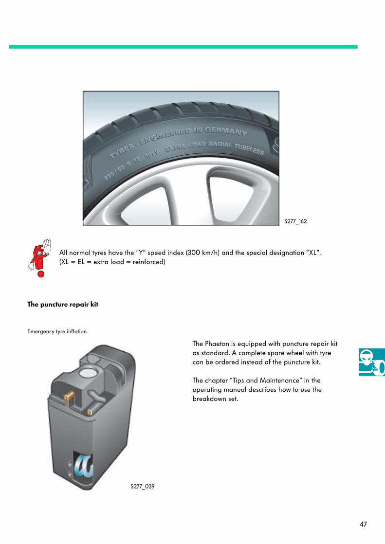
The puncture repair kit
S277_039
The Phaeton is equipped with puncture repair kit as standard. A complete spare wheel with tyre can be ordered instead of the puncture kit.
The chapter “Tips and Maintenance” in the operating manual describes how to use the breakdown set.
Emergency tyre inflation
All normal tyres have the “Y” speed index (300 km/h) and the special designation “XL”.(XL = EL = extra load = reinforced)
S277_162

48
Tyre pressure monitor
Tyre pressure monitor (TPM)
The tyre pressure monitor continuously monitors the tyre pressure while driving and also when the vehicle is stationary.
The tyre pressure monitor used in the Phaeton is a 5-wheel system.The spare wheel is also monitored and included in the system messages.
Function of the tyre pressure monitor
A measuring and transmitting unit mounted in each tyre valve sends radio signals at regular intervals to the antennas mounted in each wheel housing.The signals are then passed on to the control unit for monitoring the tyre pressure.
S277_121
Function selector switch in Infotainment
Tyre valves with wheel electronics
Receiving antenna
Control unit for monitoring tyre pressure
Combi-processor indash panel insert

49
The control unit evaluates the tyre pressures or changes in tyre pressure and sends corresponding system messages to the dash panel insert. The system messages then appear on the driver information system display.
The system recognises the following situations:
- Gradual pressure loss: The system informs the driver in time to be able to correct the tyre pressure.
- Sudden pressure loss: The system warns the driver immediately while driving.
- Excessive pressure loss when the vehicle is stationary: The system warns the driver immediately after the ignition is switched on.
If the driver has selected the “Vehicle” menu in the main information display and operating unit (ZAB), the system messages for tyre pressure monitor are displayed.

50
Tyre pressure monitor
The tyre pressure sensors G222...G226
The tyre pressure sensors are screwed to the metal valves and can be reused when the wheels or rims are changed.
The following components are integrated into a tyre pressure sensor:
The pressure sensor detects the actual tyre inflation pressure (absolute pressure measurement). The pressure is then sent to the tyre pressure monitoring control unit for evaluation.
The temperature signal is used for compensating temperature-dependent pressure changes in the tyres as well as for diagnostic purposes.
The control unit for monitoring the tyre pressure performs the temperature compensation. The measured tyre inflation pressures are normalised to a temperature of 20 °C.
The pressure sensor, temperature sensor and measuring and control electronics are integrated into one intelligent sensor.
When the driver selects “Store pressures”, the tyre inflation pressures are normalised to 20 °C.
To avoid making incorrect settings, pay particular attention that the tyre inflation pressures are checked or corrected and stored with “cold tyres”.
S277_118S277_358
Tyre pressure sensor
Metal valve
Transmittingantenna
Pressure andtemperature
sensor
Measuringand controlelectronics
Battery

51
The following information is sent from the transmitting antenna of the tyre pressure sensor:
- Individual identification number(ID code),
- Current tyre inflation pressure (absolute pressure),
- Current tyre air temperature,
- Condition of the integrated battery and
- The status, synchronisation and control information necessary for secure data transfer.
Each tyre pressure sensor has an individual identification number (ID code), which is used for “own wheel recognition”.
The ID codes
S277_120
S277_122
S277_121
0000678500
0000735700
0000597400
0000675300
0000755100

52
Tyre pressure monitor
The tyre pressure monitoring antennas R59 ... R62
The antennas for monitoring the tyre pressure receive radio signals from the tyre pressure sensors and transfer these signals to the control unit for monitoring the tyre pressure for further processing.
The tyre pressure monitor has 4 antennas for monitoring tyre pressures. They are mounted in the FL, FR, RL, RR wheel housings behind the wheel arch shells.
They are connected to the control unit for monitoring the tyre pressure using high frequency antenna lines and are allocated to the control unit according to their location.
The antennas receive all radio signals transmitted in their reception and frequency range. Each antenna receives the radio signals of all wheel sensors that are in range.
The control unit filters and selects the radio signals so that it can process the correct information.
The antennas for monitoring the tyre pressure, R59 ... R62, are located in the wheel housings behind the wheel arch shells.
The spare wheel does not have a separate antenna assigned to it. The antennas receive the radio signals that the spare wheel transmits (data messages) and transfer the signals to the control unit for monitoring the tyre pressure. The control unit recognises and stores the “fifth wheel” as the spare wheel using own wheel and position recognition.
S277_123
S277_120
53
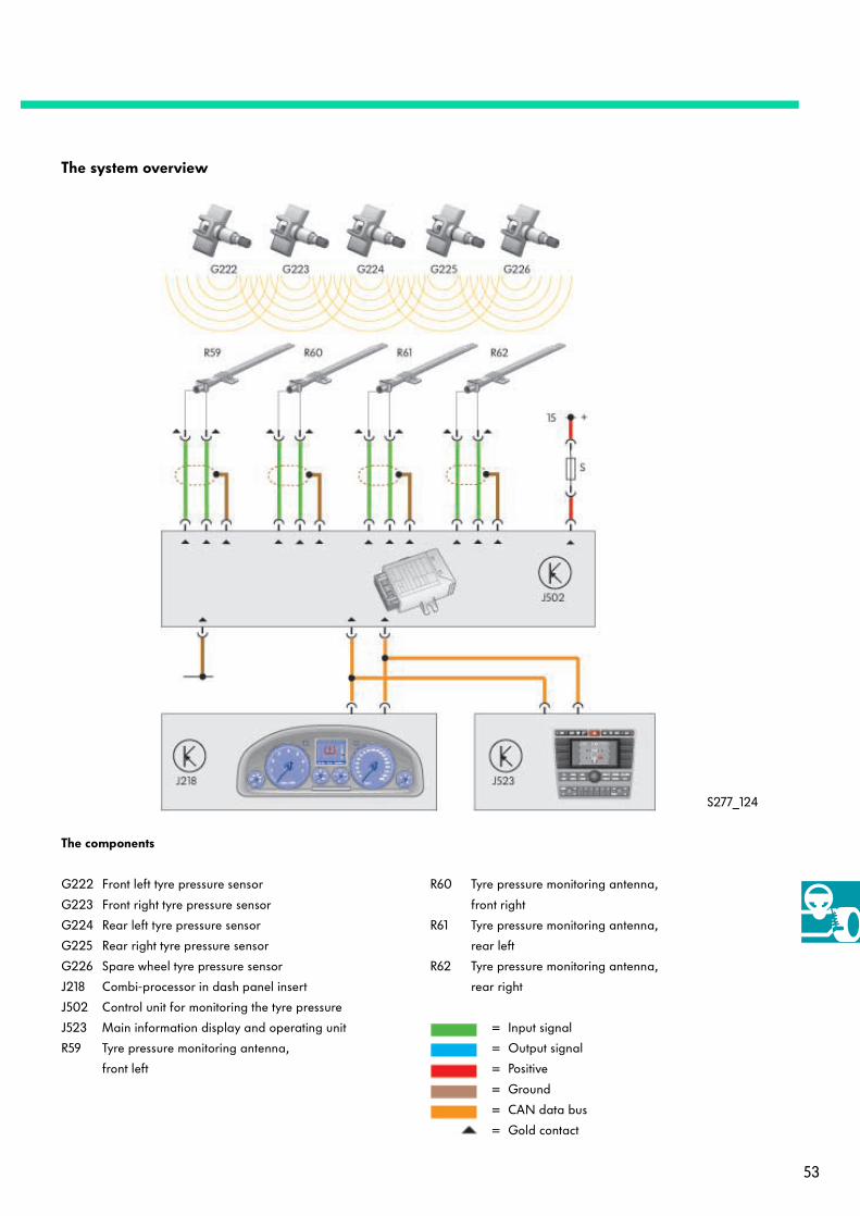
The system overview
G222 Front left tyre pressure sensor
G223 Front right tyre pressure sensor
G224 Rear left tyre pressure sensor
G225 Rear right tyre pressure sensor
G226 Spare wheel tyre pressure sensor
J218 Combi-processor in dash panel insert
J502 Control unit for monitoring the tyre pressure
J523 Main information display and operating unit
R59 Tyre pressure monitoring antenna,
front left
The components
S277_124
R60 Tyre pressure monitoring antenna,
front right
R61 Tyre pressure monitoring antenna,
rear left
R62 Tyre pressure monitoring antenna,
rear right
= Input signal
= Output signal
= Positive
= Ground
= CAN data bus
= Gold contact

54
Tyre pressure monitor
The warnings
The wheel electronics sends data messages every 54 seconds. If the wheel electronics detects a sudden change in pressure (>0.2 bar/min.), it transmits in 850 ms cycles.
The pressure falls below the coded minimum pressure of, for example, 1.9 bar for W12.
The strong warnings
Sudden pressure loss
S277_130
S277_128
Pres
sure
/bar
Time/s
Target tyre pressure stored via the menu. The system calculates the target pressures relative to 20 °C from the respective inflation pressures.
Dynamic strong warning on sudden pressure loss >0.2 bar relative to the last transmitted pressure value.
Strong warning due to sudden pressure loss >0.4 bar below the stored target tyre pressure.
Flat tyre!
55
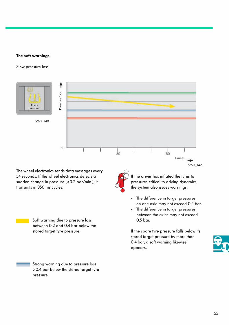
The soft warnings
Slow pressure loss
The wheel electronics sends data messages every 54 seconds. If the wheel electronics detects a sudden change in pressure (>0.2 bar/min.), it transmits in 850 ms cycles.
If the driver has inflated the tyres to pressures critical to driving dynamics, the system also issues warnings.
- The difference in target pressureson one axle may not exceed 0.4 bar.
- The difference in target pressures between the axles may not exceed 0.5 bar.
If the spare tyre pressure falls below its stored target pressure by more than 0.4 bar, a soft warning likewise appears.
S277_142
S277_140
Strong warning due to pressure loss >0.4 bar below the stored target tyre pressure.
Soft warning due to pressure loss between 0.2 and 0.4 bar below the stored target tyre pressure.
Checkpressures! Pr
essu
re/b
ar
Time/s

56
The warnings in the dash panel insert (centre display)
Tyre pressure monitor
... Display during the learn phase
... Display during radio fault
S277_146
S277_146
S277_146
The small symbol is always displayed.The large symbol only appears when the “Tyre pressure monitor” menu is open. It disappears when another menu opens.
System is learning!
System switchedoff!
... Display when switching off
Warning currentlynot possible!
S277_148
S277_148
System fault!
Faulty wheel on board!
... Display when faulty wheel on board
... Display during system fault

57
The controls
Tyre pressure monitor main menu with strong warning rear right S277_127
TPM
Spare wheelmonitoring
Inflationinformation
Adopt current pressures
Vehicle
Target pressures in [bar] at 2° C
S277_150
“Vehicle” function key
The driver is responsible for correctly setting the tyre pressures to be monitored.

58
Tyre pressure monitor
The tyre pressure monitor system main menuappears in the main information display and operating unit (ZAB) display when the “Vehicle” function key is pressed.
The following functions are stored
- Switch on/off tyre pressure monitor system- Switch on/off spare wheel monitoring- Inflation info- Adopt current pressures
The driver can specify and set the tyre pressures to be monitored within the limits coded according to the vehicle series.
After pressing the “Adopt current tyre pressures” function key and then confirming the pressures, the system stores the current tyre inflation pressures at the current tyre inner temperatures for the respective IDs.
Pressing the key also starts a new learn process for wheel assignment. To avoid receiving from external wheel electronics while learning, the system learns only when travelling faster than 5 km/h. The learning process is complete after about 15 minutes driving time.

59
Check Your Knowledge
1. What is special about the Phaeton's wheel bearings?
a. They are bolted to the wheel bearing housing as one unit.
b. They are joined to the wheel bearing housing by optimal pressing.
c. They can be installed without removing the pivot bearing or jointed shaft.
2. Which components have advantageous effects on the scrub radius and the road feedback lever arm?
a. The light-weight brake calliper, which consists of an unseparated housing in a monoblockdesign with 8 pistons and 4 brake pads.
b. The electronically controlled and speed dependent Servotronic system.
c. The virtual steering axis.
3. Where is the antenna that receives the data messages from the tyre pressure sensor in the spare wheel?
a. In the boot.
b. In the centre console between the driver and front passenger.
c. The spare wheel does not have its own antenna; the other antennas receive the signals from the spare wheel sensor and identify the sensor using its unmistakable ID code.
1.: a, c; 2.: c; 3.: c;
Only for internal use © VOLKSWAGEN AG, Wolfsburg
All rights reserved
240.2810.96.20 Issued 03/02
❀ No chlorine was used to bleach this paper
during manufacture.
277