Embed Size (px)
Citation preview
The Petri Net Markup Language:Concepts, Technology, and Tools
Jonathan Billington1, Søren Christensen2, Kees van Hee3,Ekkart Kindler4, Olaf Kummer5, Laure Petrucci6,
Reinier Post3, Christian Stehno7, and Michael Weber8
1 University of South Australia, Computer Systems Engineering Centre,[email protected]
2 University of Aarhus, Department of Computer Science,[email protected]
3 Technische Universiteit Eindhoven, Department of Math. and Computer Science{k.m.v.hee,r.d.j.post}@tue.nl
4 University of Paderborn, Department of Computer Science,[email protected]
5 CoreMedia AG, Germany,[email protected]
6 Laboratoire Specification et Verification, CNRS UMR 8643, ENS de Cachan,[email protected]
7 Carl von Ossietzky University Oldenburg, Department of Computing Science,[email protected]
8 Humboldt-Universitat zu Berlin, Computer Science Department,[email protected]
Abstract. The Petri Net Markup Language (PNML) is an XML-basedinterchange format for Petri nets. In order to support different versionsof Petri nets and, in particular, future versions of Petri nets, PNML al-lows the definition of Petri net types. Due to this flexibility, PNML isa starting point for a standard interchange format for Petri nets. Thispaper discusses the design principles, the basic concepts, and the un-derlying XML technology of PNML. The main purpose of this paper isto disseminate the ideas of PNML and to stimulate discussion on andcontributions to a standard Petri net interchange format.
1 Introduction
It has been recognised in the Petri net community for over a decade [29, 18, 2,19, 15] that it is useful to be able to transfer Petri net models between toolsthat may exist in different countries throughout the world. This would allowPetri Net tool users in geographically distributed locations to take advantage ofnewly developed facilities on other tools, for example, for analysis, simulationor implementation. The Petri net community would be able to exchange Petrinet models that are of mutual interest, perhaps for teaching a course, or in aglobal development project where teams in different countries exchange designinformation. It would allow a library of Petri net models to be created that could

be accessed worldwide via the Internet and edited, simulated and analysed ondifferent tools. This idea can be extended to the transfer of analysis results.For example, one may wish to develop Petri net models with a tool, obtain theoccurrence graph with another Petri net tool, and model check it on a third one.
To facilitate the transfer of Petri nets it is useful to develop a standardtransfer format. This was recognised in the initial proposal to establish an In-ternational standard for High-level Petri nets in 1995 [12]. Three years ago, aninitiative was taken to discuss the development of a standard interchange formatfor Petri nets by holding a workshop [1] as part of the Petri net conference inAarhus, Denmark. The principles and objectives of such an interchange formatwere discussed and different proposals for XML-based interchange formats werepresented. Since then, there have been several other meetings and discussions onsuch a format including standards meetings at the last two Petri net conferences,resulting in a mailing list being established to promote further discussion1. Still,there is no well-accepted interchange format for Petri nets to date.
The Petri Net Markup Language (PNML) [15] was one of the proposals foran interchange format at the first workshop. Though not generally accepted yet,it is currently supported by a couple of tools. Moreover, it is flexible enoughto integrate different types of Petri nets and is open for future extensions. Thismakes it a good starting point for a future standard interchange format.
In this paper, we present the concepts of PNML, its realization in XML tech-nology as well as some tools supporting its use. The purpose of this paper isto focus and promote the development of a standard interchange format. It willserve as a starting point for international standardization within the joint tech-nical committee of the International Organization for Standardization and theInternational Electrotechnical Commission (ISO/IEC) and should stimulate thediscussion of its concepts and its realization. A recent new work item proposal[14] on Petri Net techniques was accepted in 2002. It proposes the developmentof a 3 part standard for High-level Petri nets. Part 2 of this standard (ISO/IEC15909-2) will develop the transfer format. (Part 1 [13] is concerned with basicconcepts, definitions and graphical notation and Part 3 is reserved for extensions,such as the inclusion of time and modularity constructs.)
Though the basic concepts of PNML have been stable from its very beginning,there have been different extensions and minor changes. The current version isPNML 1.3, which will be discussed in this paper. However, due to its size, wecannot give here a complete description of PNML 1.3 and its realization in XML.For further technical details and examples, we refer the reader to the PNML
homepage [24]. Here, we concentrate on the principles and concepts of PNML
(Sect. 2) and its realization (Sect. 3).One of the main guiding principles of PNML is extensibility to allow for the
incorporation of future versions of Petri nets. To this end, PNML includes thedefinition of different Petri Net Types. In order to guarantee some compatibil-ity between different Petri net types, PNML suggests an evolving ConventionsDocument, which maintains the syntax (and to some extent the semantics) of all
1 See http://www.informatik.hu-berlin.de/top/PNX/ for details.
available features for defining Petri net types. In Sect. 4, we discuss the structureof the Conventions Document and some of the features covered in its presentversion. The graphical features of PNML are considered in Sect. 5, where we givea transformation to Scalable Vector Graphics (SVG [11]) in order to provide areference for the graphical appearance of a PNML file. In Sect. 6, we presentsome of the tools available for PNML and, in particular, tools that provide somesupport in reading and writing PNML files. Section 7 briefly discusses the is-sues of modularity, and the transfer of analysis results. Finally we provide someconclusions and suggestions for future work.
2 Concepts
In this section, the idea, the design principles and the concepts of PNML areexplained. PNML is designed to be a Petri net interchange format that is inde-pendent of specific tools and platforms. Moreover, the interchange format needsto support different dialects of Petri nets and must be extensible. More recently,the ideas to support the exchange of analysis information was added to this list.
An early proposal [3] for a standard Petri net transfer syntax appeared in1988. The Abstract Petri Net Notation [2] is a more recent (1995) proposal forsuch an interchange format. It tries to capture different versions of Petri netswithin a single format and provides limited features to extend it. PNML goesone step further by providing an explicit concept for defining new features andnew Petri net types.
2.1 Design Principles
Starting from the above ideas, the design of PNML was governed by the principlesof flexibility and compatibility and the need for it to be unambiguous.
Flexibility means that PNML should be able to represent any kind of Petri netwith its specific extensions and features. PNML should not restrict the featuresof some kinds of Petri nets, nor force us to ignore or to abstract from specificinformation of a Petri net when converting it to PNML. In order to achieve thisflexibility, PNML considers a Petri net as a labelled graph, where all additionalinformation can be stored in labels that can be attached to the net itself, to thenodes of the net or to its arcs.
Ambiguity is removed from the format by ensuring that the original Petrinet and its particular type can be uniquely determined from its PNML represen-tation. To this end, PNML supports the definition of different Petri net types.A Petri net type definition (PNTD) determines the legal labels for a particu-lar Petri net type. By assigning a fixed type to each Petri net, the descriptionbecomes unambiguous.
Compatibility means that as much information as possible can be exchangedbetween different types of Petri nets. In order to achieve compatibility, PNML
comes with conventions on how to define a label with a particular meaning. In aConventions Document, the syntax as well as the intended meaning of all kinds
of extensions are predefined. When defining a new Petri net type, the labels canbe chosen from this Conventions Document. When a new Petri net type complieswith these conventions for defining its own labels, the meaning of its labels iswell-defined. This allows other Petri net tools to interpret the net even if theydo not know the new Petri net type itself.
2.2 PNML Structure
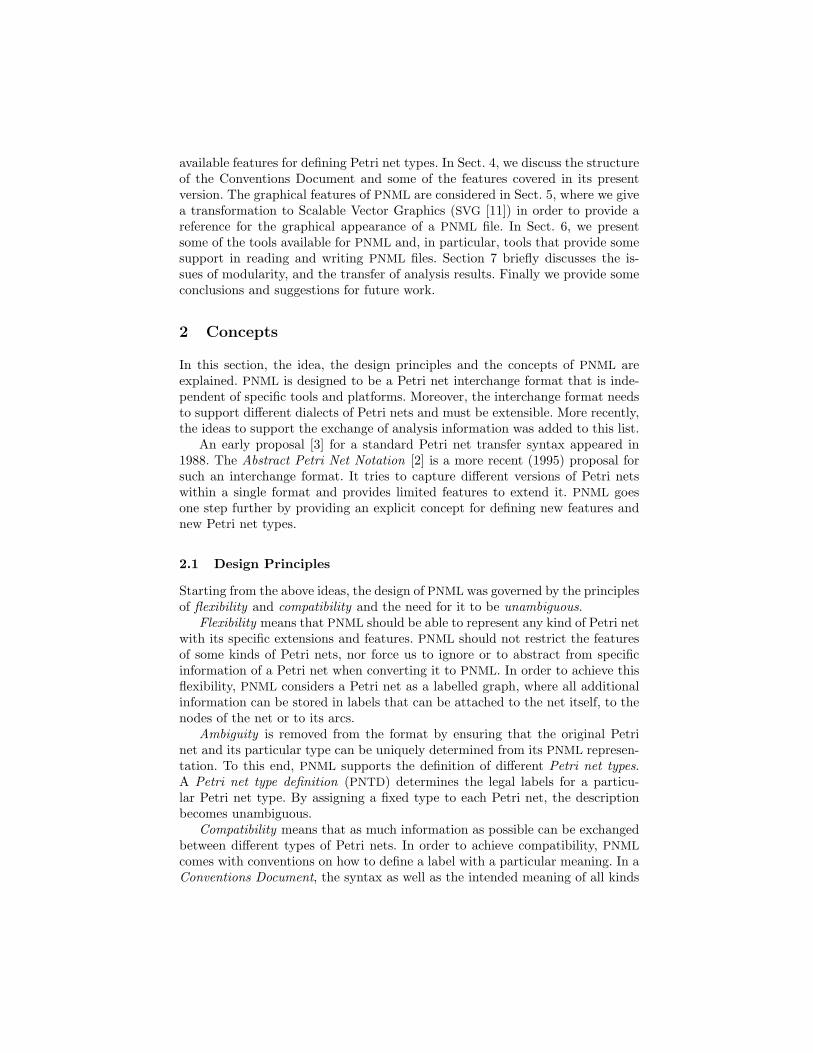
The different parts of PNML and their relationships are shown in Fig. 1. The metamodel defines the basic structure of a PNML file; the type definition interfaceallows the definition of new Petri net types that restrict the legal files of themeta model; and the feature definition interface allows the definition of newfeatures for Petri nets. These three parts are fixed once and for all. Another partof PNML, the Conventions Document, evolves. It contains the definition of a setof standard features of Petri nets, which are defined according to the featuredefinition interface. Moreover, there will be several Standard Petri Net Types,using some features from the Conventions Document and possibly others. Newfeatures can be added to the Conventions Document and new Petri net typesto the standard types when they are of common interest. Due to their evolvingnature, these documents are best published and maintained via a web site.
PNMLTypes &Features
PNMLFiles
Definition
Petri NetType
PNMLTechnology
ConventionsDocument
Petri NetFile
Petri NetFile
Petri NetFile
...
Feature Definition Interface Type Definition Interface
Meta Model
Fig. 1. Overview of the parts of PNML
2.3 Meta Model
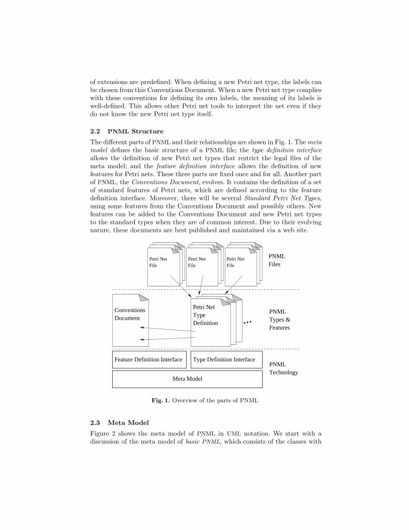
Figure 2 shows the meta model of PNML in UML notation. We start with adiscussion of the meta model of basic PNML, which consists of the classes with
thick outlines. The other classes belong to structured PNML and will be explainedlater in this section.
PetriNetFile PetriNet ToolInfo
LabelObjectidgraphics
value
*
toolversiontype
id
**
*
*
**
Node Arctarget
RefNode
source
Place RefPlace RefTrans Transition/repr
*
1
1
1ref
/repr
Page1
1
Attribute Annotation
graphics
Fig. 2. The PNML meta model
Petri nets and objects. A file that meets the requirements of PNML is calleda Petri net file; it may contain several Petri nets. Each Petri net consists ofobjects, which, basically, represent the graph structure of the Petri net2. Eachobject within a Petri net file has a unique identifier, which can be used to referto this object. In basic PNML, an object is a place, a transition or an arc. Forconvenience, a place or a transition is called a node.
Labels. In order to assign further meaning to an object, each object may havelabels. Typically, a label represents the name of a node, the initial marking ofa place, the guard of a transition, or the inscription of an arc. In addition, thePetri net itself may have some labels. For example, the declarations of functionsand variables that are used in the arc inscriptions could be labels of a high-levelPetri net. The legal labels and the legal combinations of labels are defined by2 Note that the PNML meta model allows arcs between nodes of the same kind. The
reason is that there are Petri net types with such arcs. Since Petri net types onlyrestrict the meta model, the meta model should not forbid such arcs.
the Petri net type. The type of a Petri net is defined by a reference to a uniquePetri net type definition (PNTD), which will be discussed in Sect. 3.2.
Two kinds of labels are distinguished: annotations and attributes. An anno-tation comprises information that is typically displayed as text near the corre-sponding object. Examples are names, initial markings, arc inscriptions, tran-sition guards, and timing or stochastic information. In contrast, an attributespecifies a graphical property of an object such as colour, style, form or linethickness. For example, an attribute arc type could have domain normal, read,inhibitor, reset. Another example is an attribute for classifying the nodes ofa net as proposed by Mailund and Mortensen [20]. PNML does not define howthis is done, although the Conventions Document may provide directions.
Graphical information. Each object and each annotation is equipped withgraphical information. For a node, this includes its position; for an arc, it includesa list of positions that define intermediate points of the arc; for an annotation,it includes its relative position with respect to the corresponding object3. Therecan be additional information concerning size, colour, and shape of nodes or arcs,or concerning colour, font, and font size of labels (see Sect. 3 and 5 for details).
Tool specific information. For some tools, it might be necessary to store toolspecific information, which is not supposed to be used by other tools. In order tostore this information, each object and each label may be equipped with such toolspecific information. Its format depends on the tool and is not specified by PNML.PNML provides a mechanism for clearly marking tool specific information alongwith the name and the version of the tool adding this information. Therefore,other tools can easily ignore it, and adding tool specific information will nevercompromise a Petri net file.
Pages and reference nodes. Up to now, only basic PNML has been discussed.For structuring a Petri net, there is the more advanced structured PNML. Struc-tured PNML allows us to separate different parts of a net into separate pages asknown from several Petri net tools (e. g. Design/CPN [10]). A page is an objectthat may consist of other objects – it may even consist of other pages. An arc,however, may connect nodes on the same page only4. A reference node, whichcan be either a reference transition or a reference place represents an appearanceof a node. It can refer to any node on any page of the Petri net as long as thereare no cyclic references; this guarantees that, ultimately, each reference noderefers to exactly one place or transition of the Petri net.
Reference nodes may have labels but these labels can only specify informa-tion about their appearance. They cannot specify any information about thereferenced node itself, which already has its own labels for this purpose.3 For an annotation of the net itself, the position is absolute.4 The reason is that an arc cannot be drawn from one sheet of paper to another when
printing the different pages.
Basic PNML is PNML without pages or reference nodes. A fixed transforma-tion can “flatten” any PNML net to a semantically equivalent basic PNML net.To do so, the reference nodes are merged with the nodes they refer to and pageborders are ignored (see [17] for details). This transformation can be achieved bya simple XSLT stylesheet [6]. By applying this stylesheet, a tool supporting onlybasic PNML can be used for arbitrary PNML nets5. A more powerful structuringmechanism, modular PNML [17], allows different PNML documents to referenceeach other. Modular PNML will be briefly discussed in Sect. 7.
2.4 Discussion of the Use of PNML
In this section, we briefly discuss the use of Petri net types and the definitionof Petri net features to achieve our design goals. Every Petri net file has aunique type, which is a reference (a URI – Uniform Resource Identifier) to thecorresponding Petri net type definition. This way, the syntax is unambiguouslydefined by the PNML meta model and the type definition. To be interpretedunambiguously, each Petri net type definition must have a formal semanticsthat is known by each tool that uses it.
The description of the semantics of Petri net features and Petri net types isnot formalized yet. A formalism for defining the semantics of features and forcombining the semantics of features to a semantics of a Petri net type is far fromtrivial. Working out such a formalism is a long-term project. The concepts ofPNML provide a starting point for this work.
But what about compatibility? There are times when it would be very usefulto be able to import a net, even when the semantics of the Petri net type isunknown. For example, when we have a hard copy of a net describing a complexsystem in a net dialect that our own tool does not support, but we wish to inputthe net. Manual input of the net would be very time consuming. A transferredfile would go a long way to alleviating this problem. In this case, a tool mighttry to extract as much information as possible from the net type by guessing themeaning of some labels from their names, which may result in wrong interpreta-tions. In order to allow the tool some more “educated guesses” on the meaningof labels, PNML provides the features definition interface. Each feature fixes thesyntax for the corresponding labels along with a description of their semantics.Standard features defined according to this interface will be maintained in theConventions Document. A new Petri net type definition may choose its featuresfrom these conventions by a reference to the Conventions Document (see Sect. 3.2for details). If the Petri net type chooses all its features from the ConventionsDocument, a tool not knowing the new type, but knowing the feature from theConventions Document, knows the meaning of the corresponding labels. Thenit can try to extract all the relevant information and convert the net to a Petrinet type it knows – possibly losing some information of the original net.5 It is also possible to use basic PNML with extra information to represent the page
structure, and a pair of XSLT sheets for the conversion. This allows the page struc-ture to be preserved even after processing a net with a tool that only supports basicPNML, if that tool supports the extra information.
3 PNML Technology
In this section, we will discuss how the concepts of PNML can be implemented inXML. Though the use of XML has some disadvantages6, the advantages of XML
clearly prevail. Aside from its popularity, it is platform independent, and thereare many tools available for reading, writing and validating XML documents.
There are different XML technologies that could be used for implementingPNML. RELAX NG [7] was chosen for defining the structure of a PNML docu-ment, because it was one of the first technologies7 with a module concept anda validator supporting it. This module concept was necessary for clearly sepa-rating the PNML meta model from the type definitions (PNTDs). Today, thereis also tool support for XML Schema [26]. So PNML could be easily realized inXML Schema8.
3.1 PNML Meta Model
The PNML meta model is translated into XML syntax in a straightforward man-ner. Technically, the syntax of PNML 1.3 is defined by a RELAX NG grammar,which can be found on the PNML web site [24].
PNML elements. Here, not the full grammar, but a more compact translationis presented: basically, each concrete class9 of the PNML meta model is translatedinto an XML element. This translation along with the attributes and their datatypes is given in Tab. 1. These XML elements are the keywords of PNML andare called PNML elements for short. For each PNML element, the aggregationsof the meta model define in which elements it may occur as a child element. Wehave omitted the Graphics class from the meta model shown in Fig. 2 so as notto clutter the diagram. The classes with associated graphical information areinstead indicated by an attribute “graphics”.
The data type ID in Tab. 1 describes a set of unique identifiers within thePNML document. The data type IDRef describes the same set, now as referencesto the elements of ID. The set of references is restricted to a denoted subset. Forinstance, a reference place transitively refers with its attribute ref to a place ofthe same net.
Labels. There are no PNML elements for labels because the meta model doesnot define any concrete ones. Concrete labels are defined by the Petri net types.An XML element that is not defined by the meta model (i. e. not occurring in6 One disadvantage is storage waste. But, this can be easily avoided by using a com-
pressed XML format, which is supported by most XML APIs.7 RELAX NG replaces TREX (Tree Regular Expressions for XML) [5], which was
used when first defining PNML.8 There are converters providing translation between several XML schema languages.9 A class in a UML diagram is concrete if its name is not displayed in italics.

Table 1. Translation of the PNML meta model into PNML elements
Class XML element XML Attributes
PetriNetFile <pnml>
PetriNet <net> id: IDtype: anyURI
Place <place> id: IDTransition <transition> id: IDArc <arc> id: ID
source: IDRef (Node)target: IDRef (Node)
Page <page> id: IDRefPlace <referencePlace> id: ID
ref: IDRef (Place or RefPlace)RefTrans <referenceTransition> id: ID
ref: IDRef (Transition or RefTrans)ToolInfo <toolspecific> tool: string
version: stringGraphics <graphics>
Tab. 1) is considered as a label of the PNML element in which it occurs. Forexample, an <initialMarking> element could be a label for a place, which repre-sents its initial marking. Likewise <name> could represent the name of an object,and <inscription> an arc inscription. A legal element for a label may consist offurther elements. The value of a label appears as a string in a <text> element.Furthermore, the value may be represented as an XML tree in a <structure>
element10. An optional PNML <graphics> element defines its graphical appear-ance, and further optional PNML <toolspecific> elements may add tool specificinformation to the label.
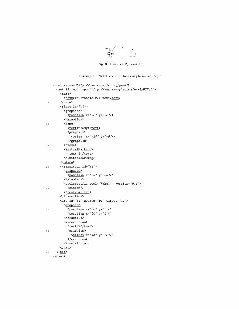
Graphics. PNML elements and labels include graphical information. The struc-ture of the PNML <graphics> element depends on the element in which it ap-pears. Table 2 shows the elements which may occur in the substructure of a<graphics> element. The <position> element defines an absolute position andis required for each node, whereas the <offset> element defines a relative posi-tion and is required for each annotation. The other sub-elements of <graphics>are optional. For an arc, the (possibly empty) sequence of <position> elementsdefines its intermediate points. Each absolute or relative position refers to Carte-sian coordinates (x, y). As for many graphical tools, the x-axis runs from leftto right and the y-axis from top to bottom. More details on the effect of thegraphical features can be found in Sect. 5.1.
10 In order to be compatible with earlier versions of PNML, the text element <value>may occur alternatively to the <text> <structure> pair.
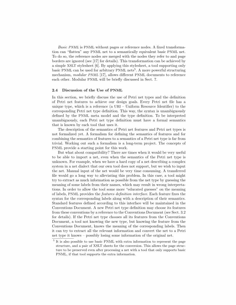
2ready
Fig. 3. A simple P/T-system
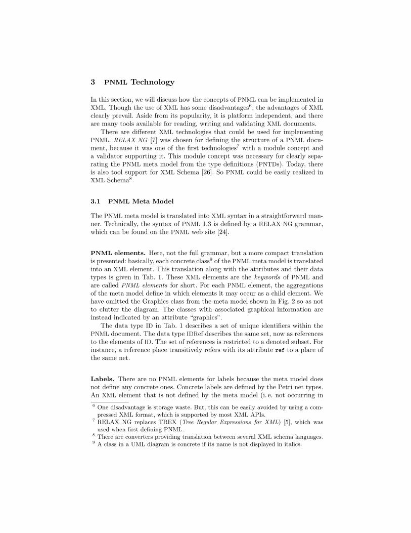
Listing 1. PNML code of the example net in Fig. 3
<pnml xmlns="http://www.example.org/pnml">
<net id="n1" type="http://www.example.org/pnml/PTNet">
<name>
<text>An example P/T-net</text>
5 </name>
<place id="p1">
<graphics>
<position x="20" y="20"/>
</graphics>
10 <name>
<text>ready</text>
<graphics>
<offset x="-10" y="-8"/>
</graphics>
15 </name>
<initialMarking>
<text>3</text>
</initialMarking>
</place>
20 <transition id="t1">
<graphics>
<position x="60" y="20"/>
</graphics>
<toolspecific tool="PN4all" version="0.1">
25 <hidden/>
</toolspecific>
</transition>
<arc id="a1" source="p1" target="t1">
<graphics>
30 <position x="30" y="5"/>
<position x="60" y="5"/>
</graphics>
<inscription>
<text>2</text>
35 <graphics>
<offset x="15" y="-2"/>
</graphics>
</inscription>
</arc>
40 </net>
</pnml>
Table 2. Elements in the <graphics> element depending of the parent element
Parent element class Sub-elements of <graphics>
Node, Page <position> (required)<dimension>
<fill>
<line>
Arc <position> (zero or more)<line>
Annotation <offset> (required)<fill>
<line>
<font>
Listing 2. Label definition
<define name="PTMarking"
xmlns:pnml="http://www.informatik.hu-berlin.de/top/pnml">
<element name="initialMarking">
<interleave>
5 <element name="text">
<data type="nonNegativeInteger"
datatypeLibrary="http://www.w3.org/2001/XMLSchema-datatypes"/>
</element>
<ref name="pnml:StandardAnnotationContent"/>
10 </interleave>
</element>
</define>
Example. In order to illustrate the structure of a PNML file, we consider thesimple example net shown in Fig. 3. Listing 1 shows the corresponding PNML
code. It is a straightforward translation, where we have labels for the names ofobjects, for the initial markings, and for arc inscriptions. Note that we assumethat the dashed outline of the transition results from the tool specific information<hidden> from an imaginary tool PN4all.
3.2 Petri Net Types
When defining a Petri net type, we firstly need to explain how labels are defined.
Label definition. Listing 2 shows the RELAX NG definition of the la-bel <initialMarking>, which represents the initial marking of a place of aP/T-system (cf. List. 1). Its value (in a <text> element) should be a natu-ral number, which is formalized by referring to the corresponding data type
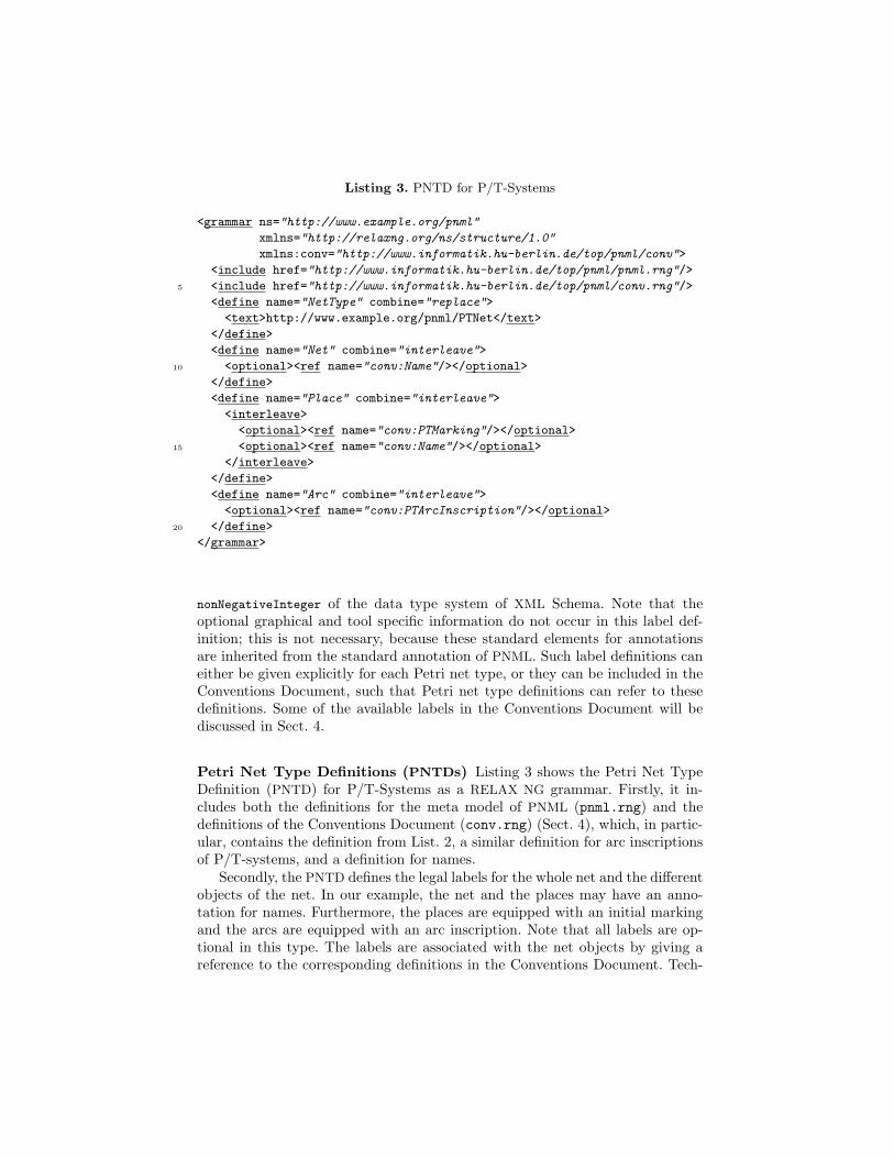
Listing 3. PNTD for P/T-Systems
<grammar ns="http://www.example.org/pnml"
xmlns="http://relaxng.org/ns/structure/1.0"
xmlns:conv="http://www.informatik.hu-berlin.de/top/pnml/conv">
<include href="http://www.informatik.hu-berlin.de/top/pnml/pnml.rng"/>
5 <include href="http://www.informatik.hu-berlin.de/top/pnml/conv.rng"/>
<define name="NetType" combine="replace">
<text>http://www.example.org/pnml/PTNet</text>
</define>
<define name="Net" combine="interleave">
10 <optional><ref name="conv:Name"/></optional>
</define>
<define name="Place" combine="interleave">
<interleave>
<optional><ref name="conv:PTMarking"/></optional>
15 <optional><ref name="conv:Name"/></optional>
</interleave>
</define>
<define name="Arc" combine="interleave">
<optional><ref name="conv:PTArcInscription"/></optional>
20 </define>
</grammar>
nonNegativeInteger of the data type system of XML Schema. Note that theoptional graphical and tool specific information do not occur in this label def-inition; this is not necessary, because these standard elements for annotationsare inherited from the standard annotation of PNML. Such label definitions caneither be given explicitly for each Petri net type, or they can be included in theConventions Document, such that Petri net type definitions can refer to thesedefinitions. Some of the available labels in the Conventions Document will bediscussed in Sect. 4.
Petri Net Type Definitions (PNTDs) Listing 3 shows the Petri Net TypeDefinition (PNTD) for P/T-Systems as a RELAX NG grammar. Firstly, it in-cludes both the definitions for the meta model of PNML (pnml.rng) and thedefinitions of the Conventions Document (conv.rng) (Sect. 4), which, in partic-ular, contains the definition from List. 2, a similar definition for arc inscriptionsof P/T-systems, and a definition for names.
Secondly, the PNTD defines the legal labels for the whole net and the differentobjects of the net. In our example, the net and the places may have an anno-tation for names. Furthermore, the places are equipped with an initial markingand the arcs are equipped with an arc inscription. Note that all labels are op-tional in this type. The labels are associated with the net objects by giving areference to the corresponding definitions in the Conventions Document. Tech-
nically, the definition extends the original definition of the net, places and arcsof the RELAX NG grammar for PNML.
3.3 High-level Petri Nets
One of the driving forces for developing PNML was the standardisation processof high-level Petri nets [13]. This standard defines High-Level Petri Net Graphs(HLPNGs) as a syntactic representation of high-level Petri nets. Here, we willbriefly sketch the idea of a PNTD for HLPNGs. Note that this definition is anexample for having a textual as well as a structural representation of the valueof a label.
The PNTD defines labels for the corresponding concepts of HLPNGs: signa-tures, variables, initial markings, arc-inscriptions, and transition guards. Arc-inscriptions and transition guards are terms over the signature and the variablesof the HLPNG. No concrete syntax is defined, but terms are defined in the usualinductive manner, providing an abstract syntax.
In the PNTD for HLPNGs, the value of a label may be represented by usinga concrete or abstract syntax. The value in a concrete syntax is represented aspure text within the label’s <text> element, the value in an abstract syntax isrepresented within the label’s <structure> element. An XML substructure withinthe <structure> element represents the inductive construction of a term from itssubterms. This way, we can exchange high-level nets between two tools that usedifferent concrete syntaxes, but have the same underlying structure (which isfixed for HLPNGs). Tools are not required to export or import abstract syntax,but if they do, interoperability with other tools is increased.
4 Conventions
The Conventions Document comprises the definitions of all standard labels, inorder to guarantee compatibility among different Petri net types.
Technically, the Conventions Document consists of a sequence of more or lessindependent label definitions as discussed in Sect. 3.2. Each label definition inthe Conventions Document must be assigned a unique name. In our examplefrom List. 2, a label with name PTMarking has been defined. Note that it is notnecessarily the name of the corresponding XML element. In the example fromList. 2, the label PTMarking is defined as the XML element <initialMarking>.For each label, the Conventions Document gives a reference to its meaning andstates in which PNML elements it may occur. The definitions in the ConventionsDocument can be used by referring to the name of a label in the ConventionsDocument as shown in List. 3.
Table 3 gives some examples of labels defined in the Conventions Document.The first column gives the name of the label. The second column gives thecorresponding XML element. The third column gives the data type of the label.If it is a simple data type, the value of the label must be text in the XML
element <text>. More complex data types (indicated by “structured” in Tab. 3),
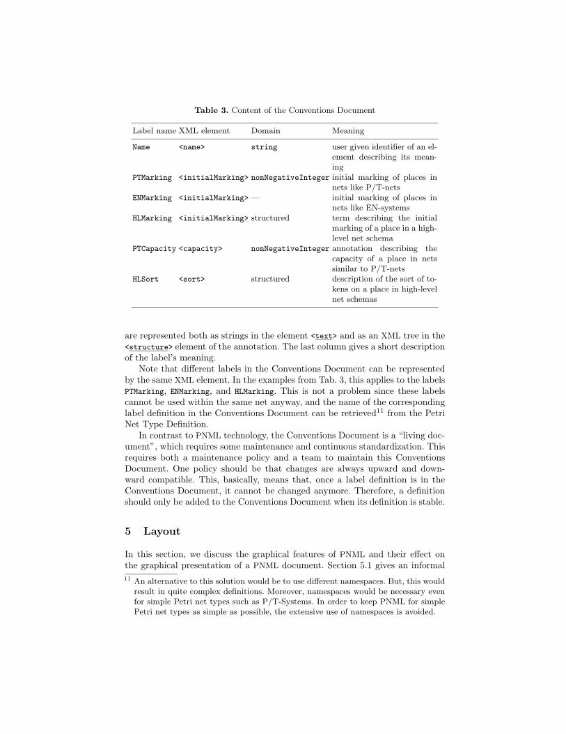
Table 3. Content of the Conventions Document
Label name XML element Domain Meaning
Name <name> string user given identifier of an el-ement describing its mean-ing
PTMarking <initialMarking> nonNegativeInteger initial marking of places innets like P/T-nets
ENMarking <initialMarking> — initial marking of places innets like EN-systems
HLMarking <initialMarking> structured term describing the initialmarking of a place in a high-level net schema
PTCapacity <capacity> nonNegativeInteger annotation describing thecapacity of a place in netssimilar to P/T-nets
HLSort <sort> structured description of the sort of to-kens on a place in high-levelnet schemas
are represented both as strings in the element <text> and as an XML tree in the<structure> element of the annotation. The last column gives a short descriptionof the label’s meaning.
Note that different labels in the Conventions Document can be representedby the same XML element. In the examples from Tab. 3, this applies to the labelsPTMarking, ENMarking, and HLMarking. This is not a problem since these labelscannot be used within the same net anyway, and the name of the correspondinglabel definition in the Conventions Document can be retrieved11 from the PetriNet Type Definition.
In contrast to PNML technology, the Conventions Document is a “living doc-ument”, which requires some maintenance and continuous standardization. Thisrequires both a maintenance policy and a team to maintain this ConventionsDocument. One policy should be that changes are always upward and down-ward compatible. This, basically, means that, once a label definition is in theConventions Document, it cannot be changed anymore. Therefore, a definitionshould only be added to the Conventions Document when its definition is stable.
5 Layout
In this section, we discuss the graphical features of PNML and their effect onthe graphical presentation of a PNML document. Section 5.1 gives an informal11 An alternative to this solution would be to use different namespaces. But, this would
result in quite complex definitions. Moreover, namespaces would be necessary evenfor simple Petri net types such as P/T-Systems. In order to keep PNML for simplePetri net types as simple as possible, the extensive use of namespaces is avoided.
overview of all graphical features. In Sect. 5.2, we discuss a precise description ofthe graphical presentation of a PNML document, i.e. an XSLT transformation [6]from PNML to the Scalable Vector Graphics (SVG) [11]. SVG is a standard fortwo-dimensional vector graphics based on XML. In combination with a standardSVG viewer, this XSLT transformation provides us with a standard viewer forPNML documents.
5.1 Graphical Information in PNML
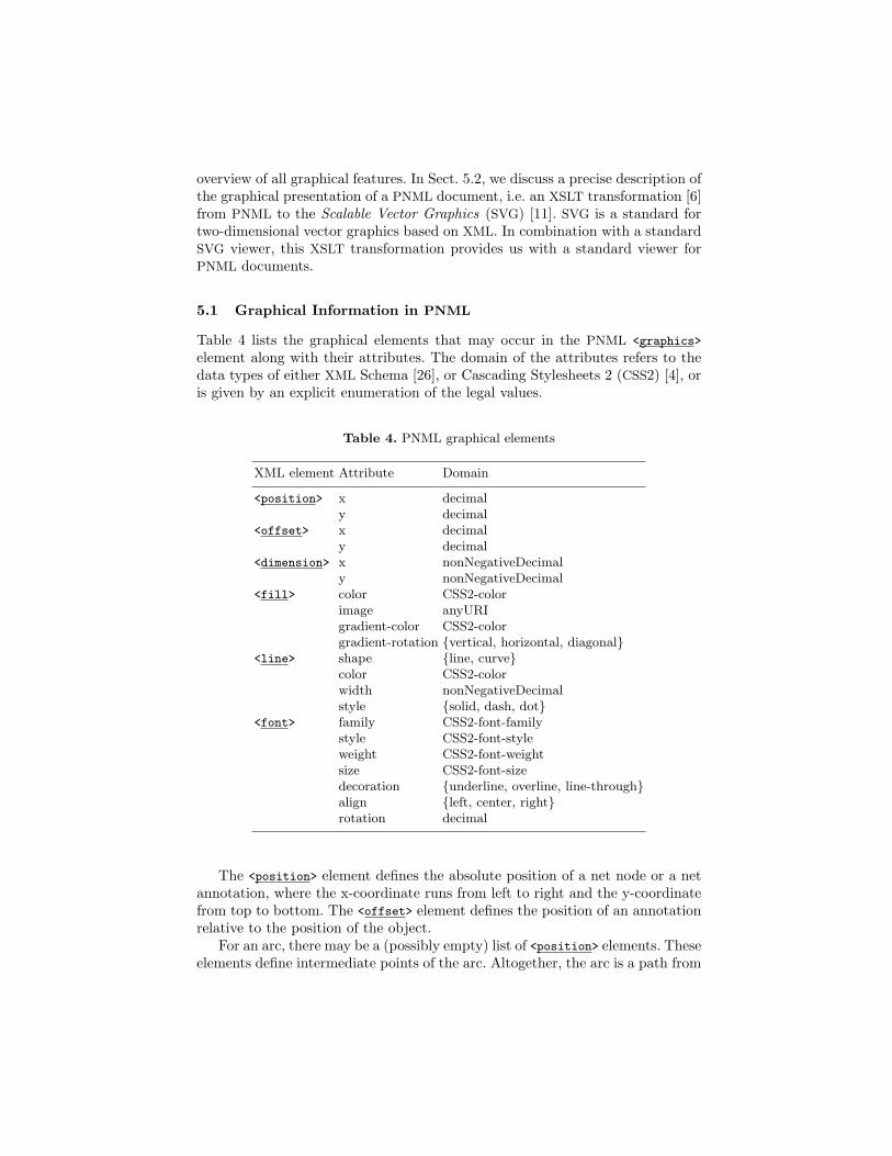
Table 4 lists the graphical elements that may occur in the PNML <graphics>
element along with their attributes. The domain of the attributes refers to thedata types of either XML Schema [26], or Cascading Stylesheets 2 (CSS2) [4], oris given by an explicit enumeration of the legal values.
Table 4. PNML graphical elements
XML element Attribute Domain
<position> x decimaly decimal
<offset> x decimaly decimal
<dimension> x nonNegativeDecimaly nonNegativeDecimal
<fill> color CSS2-colorimage anyURIgradient-color CSS2-colorgradient-rotation {vertical, horizontal, diagonal}
<line> shape {line, curve}color CSS2-colorwidth nonNegativeDecimalstyle {solid, dash, dot}
<font> family CSS2-font-familystyle CSS2-font-styleweight CSS2-font-weightsize CSS2-font-sizedecoration {underline, overline, line-through}align {left, center, right}rotation decimal
The <position> element defines the absolute position of a net node or a netannotation, where the x-coordinate runs from left to right and the y-coordinatefrom top to bottom. The <offset> element defines the position of an annotationrelative to the position of the object.
For an arc, there may be a (possibly empty) list of <position> elements. Theseelements define intermediate points of the arc. Altogether, the arc is a path from
the source node of the arc to the destination node of the arc via the intermediatepoints. Depending on the value of attribute shape of element <line>, the path isdisplayed as a polygon or as a (quadratic) Bezier curve, where points act as lineconnectors or Bezier control points.
The <dimension> element defines the height and the width of a node. Depend-ing on the ratio of height and width, a place is displayed as an ellipse rather thana circle.
The two elements <fill> and <line> define the interior and outline coloursof the corresponding element. The value assigned to a colour attribute mustbe a RGB value or a predefined colour as defined by CSS2. When the at-tribute gradient-color is defined, the fill colour continuously varies from colorto gradient-color. The additional attribute gradient-rotation defines the orien-tation of the gradient. If the attribute image is defined, the node is displayed asthe image at the specified URI, which must be a graphics file in JPEG or PNG
format. In this case, all other attributes of <fill> and <line> are ignored.For a label, the <font> element defines the font used to display the text of the
label. The complete description of possible values of the different attributes canbe found in the CSS2 specification. Additionally, the align attribute defines thejustification of the text with respect to the label coordinates, and the rotation
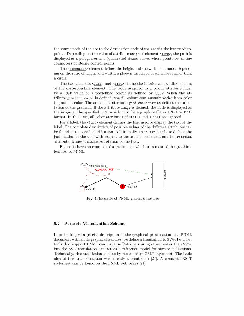
attribute defines a clockwise rotation of the text.Figure 4 shows an example of a PNML net, which uses most of the graphical
features of PNML.
Fig. 4. Example of PNML graphical features
5.2 Portable Visualization Scheme
In order to give a precise description of the graphical presentation of a PNML
document with all its graphical features, we define a translation to SVG. Petri nettools that support PNML can visualise Petri nets using other means than SVG,but the SVG translation can act as a reference model for such visualisations.Technically, this translation is done by means of an XSLT stylesheet. The basicidea of this transformation was already presented in [27]. A complete XSLT
stylesheet can be found on the PNML web pages [24].
Transformations for basic PNML. The overall idea of the translation fromPNML to SVG is to transform each PNML object to some SVG object, where theattributes of the PNML element and its child elements are used to give the SVG
element the intended graphical appearance.As expected, a place is transformed into an ellipse, while a transition is
transformed into a rectangle. Their position and size are calculated from the<position> and <dimension> elements. Likewise, the other graphical attributesfrom <fill> and <line> can be easily transformed to the corresponding SVG
attributes.An annotation is transformed to SVG text such as name: someplace. The lo-
cation of this text is automatically computed from the attributes in <offset>
and the position of the corresponding object. For an arc, this reference posi-tion is the centre of the first line segment. If there is no <offset> element, thetransformation uses some default value, while trying to avoid overlapping.
An arc is transformed into a SVG path from the source node to the targetnode – possibly via some intermediate points – with the corresponding attributesfor its shape. The start and end points of a path may be decorated with somegraphical object corresponding to the nature of the arc (e.g. inhibitor). Thestandard transformation supports arrow heads as decorations at the end, only.The arrow head (or another decoration) should be exactly aligned with thecorresponding node. This requires computations using complex operations thatare neither available in XSLT nor in SVG – the current transformation usesrecursive approximation instead.
Transformations for structured PNML. Different pages of a net shouldbe written to different SVG files since SVG does not support multi-image files.Unfortunately, XSLT does not support output to different files yet, but XSLT
2.0 will. Hence, a transformation of structured PNML to SVG will be supportedonce XSLT 2.0 is available.
The transformations for reference places and reference transitions are similarto those for places and transitions. In order to distinguish reference nodes fromother nodes, reference nodes are drawn slightly translucent and an additionallabel gives the name of the referenced object.
Type specific transformations. Above, we have discussed a transformationthat works for all PNML documents, where all annotations are displayed as text.For some Petri net types, one would like to have other graphical representationsfor some annotations. This can be achieved with customized transformations.The technical details of customized transformations are not yet fixed. Due tothe rule-based transformations of XSLT, equipping the Type Definition Interfaceand the Feature Definition Interface of PNML with some information on theirgraphical appearance seems to be feasible. Basically, each new feature can beassigned its own transformation to SVG. Adding these transformations to thestandard ones for PNML gives us a customized transformation for this Petri nettype.
6 Tools and Reference Implementation
In this section, we describe how PNML can be used in Petri net tools, howthey implement PNML and how XML techniques can help to validate and toparse PNML documents. Several Petri net tools inspired the development ofPNML. The Petri Net Kernel (Sect. 6.2) implements an object model of Petrinets similar to PNML. Renew (Sect. 6.3) was the first tool that implemented aversion of PNML. PEP (Sect. 6.4) features a Petri net based collection of tools.Design/CPN (Sect. 6.5) was one of the first Petri net tools that implemented anXML based file format. Currently, there are several Petri net tools implementingPNML as one (or as the only) file format (e. g. Renew [25], PNK [23], PEP [22],VIPtool [9]).
6.1 XML Techniques
Implementing a new file format such as PNML for an existing tool requiressome extra work. Fortunately, there are different tools and Application Pro-gramming Interfaces (APIs) for implementing parsers for XML documents ondifferent platforms and for different programming languages. Basically, there aretwo techniques supporting the parsing of XML documents, SAX and DOM. SAX
is a lightweight, event-driven interface, which is well-suited for streaming largeXML documents with minor modifications. SAX is not well-suited for implement-ing I/O-interfaces and, in particular, for implementing PNML. DOM (DocumentObject Model) provides a parser for XML documents. Then, a program has fullaccess to the document and all its elements in a tree-like structure. Moreover, itprovides a powerful reference mechanism for accessing the elements of the XML
document.The current version of PNML, the PNTDs, and the Conventions Document are
defined in the XML schema language RELAX NG [7]. There are several tools forvalidating an XML document against a RELAX NG specification (e. g. Jing12).Some special features of PNML, however, cannot be expressed in RELAX NG
yet. This concerns the correct use of a PNTD in a PNML document and thecorrectness of references. For example, a reference place must refer to a place ora reference place; it must not refer to a transition or to a reference transition.Moreover, references must not be cyclic. Currently, we are developing a Jing-based validator that takes the special features of PNML into account. See thePNML Web pages [24] for more details.
Another task is the validation of the syntactical correctness of the stringvalues of labels. If the domain of a label is defined in a known data type system(e. g. the RELAX NG internal system or the XML Schema Datatype Library), Jingcan validate these string values. Other more specific values must be validated byexternal tools.
12 See URL http://www.thaiopensource.com/relaxng/jing.html for more details.
6.2 Petri Net Kernel
PNML has been strongly influenced by the development of the Petri Net Kernel(PNK) [28, 23]. PNK is an infrastructure for building Petri net tools. Thus, itprovides methods to manage Petri nets of different types. PNK implements adata model for Petri nets that is similar to that of PNML. Each place, transi-tion, arc, or even the net may contain several labels according to the Petri nettype. Standard operations on labels (e. g. setting a value, storing a string as anexternal representation of the label value, loading, etc.) are implemented in theAPI of PNK. Label specific operations (e. g. parsing the string representing thelabel value, operating on a label, etc.), however, are implemented by the labeldeveloper.
PNK stores one or more Petri nets in a PNML file. It uses the string rep-resentation of the current label values, which is stored in the <value> tag ofthe appropriate PNML label. PNK is able to read a PNML file even if it doesnot find a PNK implementation of the Petri net type. In this case, PNK assumesthat all labels are simple string labels without special semantics. Therefore, PNK
provides a universal editor for all Petri net types. Moreover, PNK provides anAPI for loading a net and for accessing its objects, and thus can be seen as aDocument Object Model for PNML.
6.3 Renew
Renew [25] was one of the first Petri net tools to provide XML-based export andimport. While its main focus lies on reference nets (object-based Petri nets),Renew was designed as a multi-formalism tool right from the start.
In order to keep the higher levels independent of the actual Petri net type,inscriptions are always edited textually and interpreted by a configurable netcompiler later on. This approach was quite successful. As it is conceptuallyalmost identical to the label concept of PNML, it gives credibility to the claimthat labels are indeed expressive enough for practical purposes.
One special feature is that Renew distinguishes inscriptions syntactically,whenever possible. For instance, whether a label is a place type or an initialmarking is not explicitly stored; that distinction is made by the compiler. Ifwe want to conform to the PNML standard more closely, the actual type of alabel must be computed at export time, so that the correct label element can becreated.
It was evaluated whether a simple DTD suffices for the description of theformat. A DTD that permitted all intended constructs was quickly given. Butit turned out that certain important constraints were not easily expressible, sothat they had to be checked by an external tool later on. This may be acceptableor not, but it justifies the use of more powerful grammars for the definition ofPNML.
6.4 PEP
PEP [22] features a collection of tools and formalisms useful for the verificationand development of concurrent systems, combined beneath a graphical user in-terface. PEP supports a number of different modelling languages, each of themhaving a Petri net semantics. Simulation and verification is based on its Petrinet core. PEP uses stand-alone tools for most of the transformation and analy-sis tasks available. This allows easy extensions by new modelling languages orverification tools, but introduces a large number of interfaces for different filetypes.
PEP uses a common I/O library for accessing Petri net files in different for-mats. Thus, an extension to PNML files for all separate tools developed for PEP
was easy to integrate. Although the original PEP file formats for Petri nets werenot XML based, their structure was comparable to PNML. The implementationwas therefore straightforward, once the Petri net types and the API support (bylibxml2 library [30]) had been fixed.
Writing PNML files is supported by libxml2 with special output functions toadhere to XML encoding. For reading PNML, the syntax tree of the document isautomatically generated. Further processing is based on user defined functionswhich perform the gathering of the current node’s data and all of its subnodes.Parts of this processing may be delegated to further functions, allowing reuse ofcode for frequently used tags in PNML, e.g. <graphics>. Thus only one functionparseGraphics is needed, which is called for any <graphics> element found inthe input document. When a node is completely read, its data is stored in theinternal data structure of the program. To resolve references, e.g. start and endcoordinates of arcs, all possible reference targets are stored in a lookup table,allowing random access to any such element.
A converter was implemented to simplify access for tools, which use theirown implementation of the original PEP file format. The converter is based onthe functions from PEP’s I/O library. The scripts which control these externaltools now also take care of appropriate conversions, if necessary.
6.5 Design/CPN and CPN Tools
Design/CPN [10] and CPN Tools [8] both support Coloured Petri nets. De-sign/CPN has been available since 1989 and is being replaced by CPN Tools.Both tools support an XML based file format. Design/CPN exports and importsan external XML format, whereas CPN Tools has a native XML based file for-mat. A DTD for both of these formats is publicly available. Petri net models aretransferred between the two tools using an external file format converter.
Coloured Petri nets are hierarchical and tokens are complex data values.Arc inscriptions and guards comprise terms with variables, and the operationsinvolved and the types of variables are defined as annotations of the net. Thismeans that the XML format must be tailored to this information. CPN Toolswill support PNML with a PNTD for Coloured Petri nets, most likely using anexternal converter.
7 Modularity and Analysis Issues
There are two other issues that are important to raise in this paper. They aremodular PNML, and the integration of analysis results (such as net properties oroccurrence graphs and related automata) with the net that is being analysed.
Modular PNML [17] allows Petri net modules to be defined where a mod-ule’s interface definition is clearly separated from its implementation. This facil-itates the modular construction of Petri nets from instances of the modules. LikePNML itself, this module concept for PNML is independent of the Petri net type.Moreover, a Petri net in modular PNML can be transformed into a Petri net instructured PNML by a simple XSLT stylesheet (similar to the transformationfrom structured PNML to basic PNML).
The second issue is properties and analysis results. For a net, we would liketo represent its properties and analysis results in a uniform way. This wouldallow us to use different tools with different capabilities more efficiently, becauseone tool could use the results of others. For example, the analysis of a high-levelPetri net might be too complex to perform. In this case, a way of obtainingpartial results consists of analysing the net’s skeleton (i.e. the Petri net obtainedby removing the terms). Sufficient conditions (e.g. for deadlock analysis) canbe checked by transferring the skeleton to a fast dedicated Petri net tool, andreturning the results. PNML provides a technical hook for this purpose: an el-ement <properties> that could contain this additional information. A uniformrepresentation of Petri net properties and analysis results, however, is beyondthe scope of this paper. This is an interesting and important research direction.The VeriTech project [16] and the Munich Model-Checking Kit [21] can serve asguidelines for this work.
8 Conclusion
In this paper, we have presented the principles and concepts of PNML and havesketched its realization with XML technology. We have discussed the need for theformat to be extensible, to cater for evolving Petri net dialects and to includeanalysis results (such as occurrence graphs). This flexibility has been obtainedby considering the objects that we wish to transfer as labelled directed graphs.We have introduced the notion of Petri net type definitions (PNTDs) to accom-modate different Petri net dialects (and analysis results). PNTDs contain the setof legal labels for a particular net type. The concept of a Conventions Documentthat contains all the features for the various PNTDs and their semantics hasbeen suggested as a mechanism for increasing compatibility between differenttype definitions and hence different tools. The paper does not address the diffi-cult issue of providing a formal semantics for each feature and combining themto provide a semantics for each Petri net type. This is seen as important futurework.
The work presented in this paper provides a starting point for experimentingwith using PNML to transfer Petri nets between tools. We encourage the Petri
net community to participate in these experiments and provide the full detailsof PNML [24] for this purpose. The experience gained in experimenting with thetransfer format will lead to formulating a set of requirements and a relativelymature baseline document needed for the development of an International Stan-dard within the work of project ISO/IEC 15909. Although not addressing theproblem of combining features, the current Final Committee Draft of the Stan-dard for High-level Petri Nets [13] does include an example of how the semanticsof a Petri net type (in this case High-level Petri Net Graphs) may be provided(see clause 9). The work on semantics will need to be harmonised with ISO/IEC15909.
Moreover, there are many other matters that will require significant futurework. These include: user definable defaults for the graphical information ofPNML elements; the realization of type specific graphical representations forPNML elements; and the policy and procedures required for maintaining theConventions Document.
Acknowledgements. Many people from the Petri net community have contributedto the concepts of PNML during discussions of earlier versions, by making proposals,and by asking questions. Here is an incomplete list of those who contributed: MatthiasJungel, Jorg Desel, Erik Fischer, Giuliana Franceschinis, Nisse Husberg, Albert Koel-mans, Kjeld Høyer Mortensen, Wolfgang Reisig, Stephan Roch, Karsten Schmidt, aswell as all former members of the DFG research group “Petri Net Technology”. Thanksto all of them. Moreover, we would like to thank the DFG (German Research Council)for supporting the work on PNML.
References
1. R. Bastide, J. Billington, E. Kindler, F. Kordon, and K. H. Mortensen, editors.Meeting on XML/SGML based Interchange Formats for Petri Nets, Arhus, Den-mark, June 2000. 21st ICATPN.
2. F. Bause, P. Kemper, and P. Kritzinger. Abstract Petri net notation. Petri NetNewsletter, 49:9–27, October 1995.
3. G. Berthelot, J. Vautherin, and G. Vidal-Naquet. A syntax for the description ofPetri nets. Petri Net Newsletter, 29:4–15, April 1988.
4. B. Bos, H. W. Lie, C. Lilley, and I. Jacobs (eds.). Cascading Style Sheets, level 2– CSS2 Specification. URL http://www.w3.org/TR/CSS2, 1998.
5. J. Clark. TREX – tree regular expressions for XML. URL http://www.
thaiopensource.com/trex/. 2001/01/20.6. J. Clark (ed.). XSL Transformations (XSLT) Version 1.0. URL http://www.w3.
org/TR/XSLT/xslt.html, 1999.7. J. Clark and M. Murata (eds.). RELAX NG specification. URL http://www.
oasis-open.org/committees/relax-ng/. 2001/12/03.8. CPN Tools. URL http://www.daimi.au.dk/CPNtools. 2001/09/11.9. J. Desel, G. Juhas, R. Lorenz, and C. Neumair. Modelling and validation with
VipTool. In Conference on Business Process Management, Tool Presentation, 2003.10. Design/CPN. URL http://www.daimi.au.dk/designCPN/. 2001/09/21.11. J. Ferraiolo, F. Jun, and D. Jackson (eds.). Scalable Vector Graphics (SVG) 1.1
Specification. URL http://www.w3.org/TR/SVG11/, 2003.
12. ISO/IEC/JTC1/SC7. Subdivision of project 7.19 for a Petri net standard.ISO/IEC/JTC1/SC7 N1441, October 1995.
13. ISO/IEC/JTC1/SC7. Software Engineering - High-Level Petri Nets - Concepts,Definitions and Graphical Notation. ISO/IEC 15909-1, Final Committee Draft,May 2002.
14. ISO/IEC/JTC1/SC7 WG19. New proposal for a standard on Petri net techniques.ISO/IEC/JTC1/SC7 N2658, June 2002.
15. M. Jungel, E. Kindler, and M. Weber. The Petri Net Markup Language. Petri NetNewsletter, 59:24–29, 2000.
16. S. Katz and O. Grumberg. VeriTech: Translating among specifications and verifi-cation tools. Technical report, The Technion, Haifa, Israel, March 1999.
17. E. Kindler and M. Weber. A universal module concept for Petri nets. An imple-mentation-oriented approach. Informatik-Berichte 150, Humboldt-Universitat zuBerlin, June 2001.
18. A. M. Koelmans. PNIF language definition. Technical report, Computing ScienceDepartment, University of Newcastle upon Tyne, UK, July 1995. version 2.2.
19. R. B. Lyngsø and T. Mailund. Textual interchange format for high-level Petri nets.In Proc. Workshop on Practical use of Coloured Petri Nets and Design/CPN, pages47–63, Department of Computer Science, University ofArhus, Denmark, 1998. PB-532.
20. T. Mailund and K. H. Mortensen. Separation of style and content with XML inan interchange format for high-level Petri nets. In Bastide et al. [1], pages 7–11.
21. The Model-Checking Kit. URL http://wwwbrauer.in.tum.de/gruppen/theorie/
KIT/. 2003/02/18.22. The PEP Tool. URL http://parsys.informatik.uni-oldenburg.de/~pep/.
2002/07/29.23. The Petri Net Kernel. URL http://www.informatik.hu-berlin.de/top/pnk/.
2001/11/09.24. Petri Net Markup Language. URL http://www.informatik.hu-berlin.de/top/
pnml/. 2001/07/19.25. Renew: The Reference Net Workshop. URL http://www.renew.de. 2002/03/04.26. M. Sperberg-McQueen and H. Thompson (eds.). XML Schema. URL http://www.
w3.org/XML/Schema, April 2000. 2002-03-22.27. C. Stehno. Petri Net Markup Language: Implementation and Application. In
J. Desel and M. Weske, editors, Promise 2002, Lecture Notes in Informatics P-21,pages 18–30. Gesellschaft fur Informatik, 2002.
28. M. Weber and E. Kindler. The Petri Net Kernel. In H. Ehrig, W. Reisig, G. Rozen-berg, and H. Weber, editors, Petri Net Technology for Communication Based Sys-tems, Lecture Notes in Computer Science 2472. Springer, Berlin Heidelberg, 2002.To appear.
29. G. Wheeler. A textual syntax for describing Petri nets. Foresee design document,Telecom Australia Research Laboratories, 1993. version 2.
30. The XML C library for Gnome. URL http://xmlsoft.org. 2003/01/23.


![Science & Scientific Method. DAIMIHenrik Bærbak Christensen2 Literature [Wikipedia, 2005] –Scientific Method. [Carter, 1996] –The Scientific Method. [Zobel,](https://img.pdfslide.us/doc/110x75/56649d585503460f94a3733a/science-scientific-method-daimihenrik-baerbak-christensen2-literature-wikipedia.jpg)