Embed Size (px)
Citation preview

104
Transactions of The Japan Institute of Electronics Packaging Vol. 3, No. 1, 2010
[Tutorial Paper]
The Performance of Lead-Free Solders During a Long-Distance
Electric Vehicle RaceKazuhiro Nogita*, Mathew C. Greaves**, Benjamin D. Guymer**, Bernard B. Walsh**, James M. Kennedy***,
Michael D. Duke****, and Tetsuro Nishimura*****
*School of Mechanical and Mining Engineering, The University of Queensland, St. Lucia, Brisbane QLD 4072, Australia
**Ultramotive Technologies Pty. Ltd., Unit 1 / 30 Walker Street, Tennyson QLD 4105, Australia
***Tritium Pty Ltd., Unit 1 / 30 Walker Street, Tennyson QLD 4105, Australia
****School of Engineering, Faculty of Science and Engineering, The University of Waikato, Hamilton 3240, New Zealand
*****Nihon Superior Co. Ltd., NS Bldg., 1-16-15 Esaka-Cho, Suita City, Osaka 564-0063, Japan
(Received August 10, 2010; accepted September 2, 2010)
Abstract
The authors produced a demonstration electric vehicle, “Deep Green Research,” based on a Honda Civic, in which critical
electrical connections were soldered with a lead-free Sn–Cu–Ni–Ge alloy. This paper reports on the team’s participation
and completion in the Global Green Challenge, the world’s largest solar car and eco car race, from Darwin to Adelaide,
Australia that was run in late October, 2009. The successful completion of this course under the harsh conditions of the
Australian outback proved the high reliability of the Sn–Cu–Ni–Ge lead-free solder joints in the control panels, cables,
and connectors that had to carry the heavy current required to propel the vehicle over long distances at speeds of up
to 104 km/hour. The vehicle set a new record for the longest distance travelled on a single charge by a car that satisfies
relevant Australian safety regulations. This distance of 360 km was achieved using lithium-ion batteries with a total capac-
ity of 33 kWh and resulted in an award in the category “Modified Production Class — Small Car (Electric)”.
Keywords: Lead-free Solder, Electric Vehicle, Waste Electrical and Electronic Equipment, End-of-Life Vehicle
(ELV) Directive
1. IntroductionThe rapid increase in the volume of scrapped electrical
and electronic equipment that is finding its way into landfill
sites has prompted concern about the possibility of lead in
the solders used in the assembly of this equipment leach-
ing into the groundwater.[1] This concern has prompted
the European Union to issue a directive that has effectively
banned the use of lead-containing solders in such equip-
ment placed on the market after 1st July 2006. Currently
there are exemptions in the regulations for certain applica-
tions such as photovoltaic or electric vehicles where there
are concerns that reliability could be jeopardised by a tran-
sition from lead-based to lead-free solders.[2] Recent
announcements by the EU make it clear that these exemp-
tions are temporary so that it is imperative that the reliabil-
ity of lead-free alternatives be proven and alloys further
developed for specific applications if required. At present,
the most utilised group of lead-free solders is aimed at
replacing Sn–37Pb solder for low-middle temperature
applications, below 250°C.[3] Although the lead-rich Sn–
Pb high-temperature solders are temporarily exempted
from the directives on Waste Electrical and Electronic
Equipment (WEEE) and the Restriction of Hazardous Sub-
stances (RoHS), the End-of-Life Vehicle (ELV) directive
will require the removal of lead in vehicles by 2013. Obvi-
ously, this will lead to an increasing demand for reliable
and low cost lead-free solders for combustion engine vehi-
cles, hybrid, and full electric vehicles. Previous research
has shown that a successful lead-free solder for low-middle
temperature applications can be based on the Sn–Cu
system with trace additions of Ni (Sn–0.7wt%Cu–
0.05wt%Ni),[4, 5] and a commercial alloy based on that dis-
covery, (SN100C®) also has an addition of < 0.01 wt% Ge
to further enhance its behaviour as a practical solder.
105
Due to the above considerations it is timely to consider
the application of lead-free solder alloys for use in and
around the engines and electric motors of a range of vehi-
cles. Using lead-free solder alloys in an electric vehicle par-
ticipating in the world’s largest solar and eco car race was
considered an opportunity both to test the reliability of an
existing lead-free solder and to promote its use to the gen-
eral public. The authors therefore formed a team to pro-
duce a demonstration electric vehicle utilising solders
based on the lead-free Sn–Cu–Ni–Ge system.
This paper reports on the participation of that team in
the world’s largest solar car and eco car race, the Global
Green Challenge,[6] from Darwin to Adelaide, Australia in
late October 2009 with their demonstration vehicle.
2. The Concept of the “Deep Green Research”Electric Vehicle
The concept underlying the “Deep Green Research”
project was to design a car that is suitable for city driving
and that has minimal impact on the environment. The
approach taken was to use an existing car body that
already complies with the Australian safety requirements
for a passenger vehicle so that all attention could be
focussed on replacing the petrol-fuelled internal combus-
tion engine and its mechanical drive train with a battery-
driven electric motor.
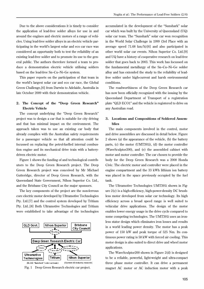
Figure 1 shows the funding of and technological contrib-
utors to the Deep Green Research project. The Deep
Green Research project was conceived by Mr Michael
Gutteridge, director of Deep Green Research, with the
Queensland State Government, Nihon Superior Co. Ltd.,
and the Brisbane City Council as the major sponsors.
The key components of the project are the non-ferrous
core electric motor developed by Ultramotive Technologies
Pty. Ltd.[7] and the control system developed by Tritium
Pty. Ltd..[8] Both Ultramotive Technologies and Tritium
were established to take advantage of the technologies
accumulated in the development of the “Sunshark” solar
car which was built by the University of Queensland (UQ)
solar car team. The “Sunshark” solar car won recognition
in the World Solar Challenge in 1999 (3rd Place with an
average speed 71.68 km/h)[6] and also participated in
other world solar car events. Nihon Superior Co. Ltd.[9]
and UQ have a history of cooperative research on lead-free
solder that goes back to 2003. This work has focussed on
the fundamental metallurgy of the Sn–Cu–Ni–Ge solder
alloy and has extended the study to the reliability of lead-
free solder under high-current and harsh environmental
conditions.
The roadworthiness of the Deep Green Research car
has now been officially recognized with the issuing by the
Queensland Department of Transport of a registration
plate “QLD ECO1” and the vehicle is registered to drive on
any Australian road.
3. Locations and Compositions of Soldered Assem-blies
The main components involved in the control, motor
and drive assemblies are discussed in detail below. Figure
2 shows (a) the appearance of the vehicle, (b) the battery
parts, (c) the motor (UMT391i), (d) the motor controller
(WaveSculptor200), and (e) the assembled cabinet with
motor and motor controller. The car chosen to provide the
body for the Deep Green Research was a 2008 Honda
Civic. The electric motor and controller were placed in the
engine compartment and the 33 kWh lithium ion battery
was placed in the space previously occupied by the fuel
tank.
The Ultramotive Technologies UMT391i shown in Fig-
ure 2(c) is a high-efficiency, high-power-density DC brush-
less motor developed from solar car technology. Its high
efficiency across a broad speed range is well suited to
vehicular drive applications. The design of the motor
enables lower energy usage in the drive cycle compared to
some competing technologies. The UMT391i uses an iron-
less stator design which eliminates iron losses and results
in a world leading power density. The motor has a peak
power of 150 kW and peak torque of 525 Nm. Its con-
tinuous power rating is 58 kW with forced air cooling. This
motor design is also suited to direct drive and wheel motor
applications.
The WaveSculptor200 shown in Figure 2(d) is designed
to be a reliable, powerful, light-weight and ultra-compact
three phase motor controller. It can drive a permanent
magnet AC motor or AC induction motor with a peakFig. 1 Deep Green Research electric car project.
Nogita et al.: The Performance of Lead-Free Solders (2/6)

106
Transactions of The Japan Institute of Electronics Packaging Vol. 3, No. 1, 2010
power of 150 kW and an average power of 75 kW. The
motor controller uses a CAN bus to command the vehicle,
broadcast telemetry, configure the controller, and update
the firmware. It controls the motor current, vehicle speed,
and battery current and can reduce battery current to
within the maximum and minimum battery pack voltages.
The WaveSculptor200 is designed to be mounted under
the vehicle’s bonnet and is therefore water and dust proof.
All cooling is provided via a liquid cooling loop.
The soldered joints in the vehicle are listed in Table 1.
The composition of SN100C®4 is Sn–4wt%Cu–0.05wt%
Ni+Ge, and that of SN100C® is Sn–0.7wt%Cu–0.05wt%
Ni+Ge. SN100C® was used concurrently with Sn–37Pb in
a range of locations throughout the vehicle and both alloys
(a) (d)
(b) (e)
(c)
Fig. 2 (a) The appearance of the vehicle, (b) battery parts,(c) motor (UMT391i), (d) motor controller (WaveSculptor200),and (e) assembled cabinet.

107
performed without incident for the duration of the Eco
Challenge. This concurrent testing demonstrates that the
SN100C® solder was capable of at least matching the per-
formance of the older generation of lead-containing alloys
it is replacing for the applications listed in Table 1. Details
of soldering conditions (soldering methods, temperatures,
Table 1 A list of soldered joints.
No. Parts Soldering Parts Details Solders SolderingCondition Soldering Temp. Flux
MaxCurrentduringracing
MaxTemp.duringracing
1 Wire Motor litz wire terminations SN100C4 Dipping App. 450C pot temp None 300A 90C
2 Wire Inductor litz wire terminations SN100C4 Dipping App. 450C pot temp None 300A 85C
3 Motor Controller Motor controller gate drive board SN100C Hand App. 400C iron tip temp (30) + NC254 gel n/a 55C
4 Motor Controller* Motor controller DSP board Sn37Pb Hand App. 375C iron tip temp NC254 gel n/a 55C
5 BMS BMS through-hole components (110 boards) SN100C Hand App. 400C iron tip temp (30) + NC254 gel n/a 45C
6 BMS* BMS surface-mount components (110 boards) Sn37Pb Paste Reflow App. 250C reflow temp NC254 in paste n/a 45C
7 BMS* Precharge / BMS master Sn37Pb Hand App. 375C iron tip temp NC254 gel n/a 45C
8 Driver controls Driver controls SN100C Hand App. 400C iron tip temp (30) + NC254 gel n/a 45C
9 Fan/Pump driver Fan/Pump driver SN100C Hand App. 400C iron tip temp (30) + NC254 gel n/a 45C
(a) (c)
(b)
(d)
Fig. 3 (a) Photograph of motor litz wire soldered with SN100C®4, (b) cross-sectioned view, (c) low magnification, and (d)high-magnification optical micrographs.
Nogita et al.: The Performance of Lead-Free Solders (4/6)

108
Transactions of The Japan Institute of Electronics Packaging Vol. 3, No. 1, 2010
and flux), expected maximum electric current and temper-
ature experienced by the solder joints in each location are
also shown in Table 1. SN100C® was used for the motor
controller gate drive PCB, battery management system
(BMS), driver controls, and Fan/Pump driver.
The greatest demand imposed on the solder in this vehi-
cle was in the joint that attaches directly to the motor (both
motor litz wire terminations and inductor litz wire termina-
tions) where currents of up to 300 A (23.34 A/mm2) and
temperatures of up to 90°C could be expected, and for this
application SN100C®4 solder was used. Figures 3(c) and d
show optical micrographs of cross-sections of a motor litz
wire termination with SN100C®4 solder before the vehicle
had seen any service.
It can be clearly seen that the (Cu,Ni)6Sn5 intermetallic
compound (IMC) has formed spontaneously around the
circumference of individual copper wires during dipping
and cooling. A high-temperature dipping process was
required for this application as the wire is pre-coated with
a protective/insulating layer that must be burnt off during
the joining process. The solder material is in direct contact
with the copper at all locations and no significant erosion
of the wire has occurred. While the interfacial IMC has a
columnar morphology there is no visible cracking between
individual IMC grains and the copper wire. Mechanical
properties such as Young’s modulus and hardness were
measured by nano-indentation, and reported elsewhere.[10]
4. Global Green Challenge — Eco Car RacingThe Global Green Challenge,[6] first held in 1987 as
“The World Solar Challenge” from Darwin to Adelaide,
Australia, is the world’s largest event for alternative energy
cars. In 2009, for the first time, the event was split into two
categories, the “Solar Car Challenge” for cars powered
only by direct solar-generated electricity and the “Eco
Challenge” for cars powered by other alternative energy
sources. In previous years cars other than those directly
powered by solar-generated electricity could participate
only for demonstration purposes. The Eco Challenge cate-
gory, introduced in response to the growing interest in
other power sources, created an opportunity for cars like
Deep Green Research to fully participate in this major
global event.
Major global car manufacturers were well represented
amongst the 14 vehicles participating in the Eco Challenge
section of the event. Ford (USA), Suzuki (Japan), Holden
(Australia), Hyundai (Korea), and BMW Australia entered
cars powered by petrol and/or ethanol. Deep Green
Research was one of only two battery-powered cars in the
event, the other being the Tesla from the USA. However,
as the Tesla was not registered within Australia, it could
carry only the “SUN” registration plate that restricts the
vehicle to the race. During the race the Tesla, which car-
ries lithium ion batteries with a storage capacity of 53
kWh, set a new world record for the distance travelled on
a single battery charge, 501 km. The distance achieved by
Deep Green Research (33 kWh lithium ion battery), 360
km, is a new record for a car that also satisfies Australian
safety regulations. Furthermore, in terms of kilometers per
unit of energy stored in the battery, Deep Green Research
outperformed the Tesla by a substantial margin. The 1,300
km successfully driven by Deep Green Research qualified
the vehicle for the Modified Production Class — Small
(Electric) Award. In the Solar Challenge category the
entry from Tokai University (Japan) was the winner, break-
ing the previous record by a substantial margin.
Despite the harsh environment of central Australia and
the current and temperature loads applied during the oper-
(a)
(b)
Fig. 4 The appearance of (a) Battery Management System(BMS) and (b) Motor controller gate drive PCB withSN100C® solder after racing. No solder joint faults aredetected.

109
ation of the motor, none of the solder joints failed. Figure
4 shows (a) the Battery Management System (BMS) and
(b) Motor controller gate drive PCB after the race.
Although there were no failures of soldered joints, the
demanding conditions did result in one failure during the
race: the burning out of a resistor in one of the control cir-
cuits. Overall, the race experience confirmed that lead-free
Sn–Cu–Ni–Ge is at least as reliable in this application as
the standard lead-containing solders that will eventually
have to be phased out because of widening restrictions on
the use of lead in electrical and electronic circuitry.
Although further confirmatory testing is required, it is
believed that the best match in a demanding application
for a SN100C® alloy was the use of the SN100C®4 high
temperature variant for the dip soldering of the litz wire
terminations that have to carry up to 300 A (23.34 A/mm2)
of current.
5. ConclusionsA concept electric vehicle was created by fitting a con-
ventional automotive platform with an electric motor,
drive, and control system. This vehicle met Australian
safety regulations and received awards for its perfor-
mance in The Global Green Challenge. The key compo-
nents of the project are the non-ferrous-core electric
motor developed by Ultramotive Technologies Pty. Ltd.,
and the control system developed by Tritium Pty. Ltd.,
with Nihon Superior’s SN100C® lead-free solder (Sn–
0.7Cu–0.05Ni+Ge or Sn–4Cu–0.05Ni+Ge) providing the
essential high-reliability soldered connections. The road-
worthiness of the Deep Green Research car has been offi-
cially recognized with the issuing by the Queensland
Department of Transport of a registration plate “QLD
ECO1” which means that it can drive on any Australian
road. The concept of Deep Green Research proved suc-
cessful with each of the individual components working
without significant failure, including the lead-free solder
alloys which were subject to harsh operating conditions.
Continued development of concept vehicles such as Deep
Green Research will be required to replace existing com-
bustion powered vehicles with low environmental-impact
alternatives.
AcknowledgmentsThe authors acknowledge Mr Michael Gutteridge,
director of Deep Green Research project. Queensland
Government, Nihon Superior Co. Ltd., and The Brisbane
City Council are acknowledged for their financial support.
Mr. K. Sweatman of Nihon Superior Co. Ltd., Dr. D. Finn,
Mr C. Walsh, Dr. M. MacDiarmid of Tritium Pty. Ltd., Mr.
S. te Brinke of the University of Twente, and Mr. J. Read,
Dr. S. D. McDonald of the University of Queensland are
acknowledged for their support. K. Nogita is funded by a
Smart Futures Fellowship, Queensland Government,
Australia.
References
[1] Y. Li, K.-S. Moon, and C. P. Wong, “Electronics with-
out lead,” Science, Vol. 308, pp. 1419–1420, 2005.
[2] J. Hwang, Implementing lead-free Electronics. 2004:
McGraw-Hill. 473.
[3] K. Suganuma, S.-J. Kim, and K.-S. Kim: “High-
temperature lead-free solders: Properties and possi-
bilities,” JOM, Vol. 61, pp. 64–71, 2009.
[4] K. Nogita, C. M. Gourlay, and T. Nishimura, “Crack-
ing and phase stability in reaction layers between
Sn–Cu–Ni solders and Cu substrates,” JOM, Vol.
61, pp. 45–51, 2009.
[5] K. Nogita, et al., “Inhibiting cracking of interfacial
Cu6Sn5 by Ni additions to Sn-based lead-free sol-
ders,” Transactions of The Japan Institute of Elec-
tronics Packaging (Trans JIEP), Vol. 2, pp. 46–54,
2009.
[6] Global Green Challenge. [Available from: http://
www.globalgreenchallenge.com.au/.]
[7] Ultramotive Technologies Pty. Ltd.. [Available from:
http://www.ultramotive.com.au/.]
[8] Tritium Pty. Ltd.. [Available from: http://www.tri-
tium.com.au/.]
[9] Nihon Superior Co. Ltd.. [Available from: http://
www.nihonsuperior.co.jp/english/.]
[10] D. Mu, et al., “Formation and mechanical properties
of intermetallic compounds in Sn–Cu high-
temperature lead-free solder joints,” Materials
Science Forum, Vol. 654–656, pp. 2450–2454,
2010.
Nogita et al.: The Performance of Lead-Free Solders (6/6)