Embed Size (px)
Citation preview
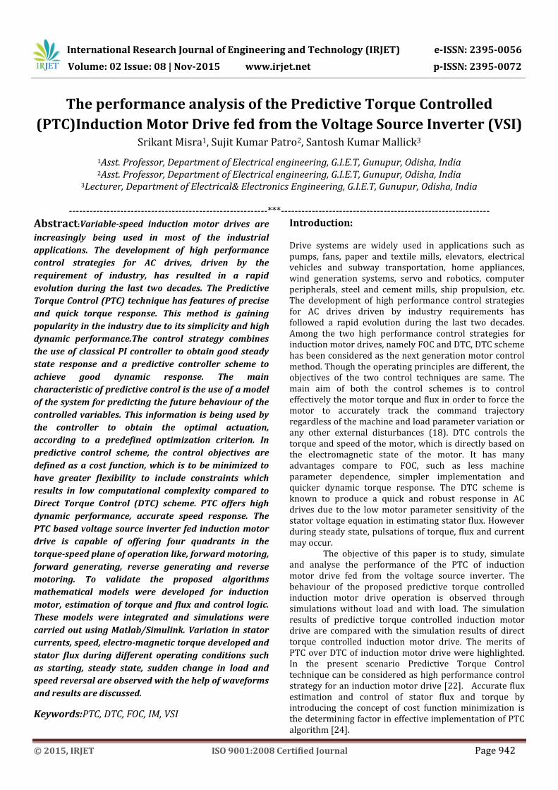
International Research Journal of Engineering and Technology (IRJET) e-ISSN: 2395-0056
Volume: 02 Issue: 08 | Nov-2015 www.irjet.net p-ISSN: 2395-0072
© 2015, IRJET ISO 9001:2008 Certified Journal Page 942
The performance analysis of the Predictive Torque Controlled
(PTC)Induction Motor Drive fed from the Voltage Source Inverter (VSI) Srikant Misra1, Sujit Kumar Patro2, Santosh Kumar Mallick3
1Asst. Professor, Department of Electrical engineering, G.I.E.T, Gunupur, Odisha, India 2Asst. Professor, Department of Electrical engineering, G.I.E.T, Gunupur, Odisha, India
3Lecturer, Department of Electrical& Electronics Engineering, G.I.E.T, Gunupur, Odisha, India
----------------------------------------------------------***-------------------------------------------------------------
Abstract:Variable-speed induction motor drives are
increasingly being used in most of the industrial
applications. The development of high performance
control strategies for AC drives, driven by the
requirement of industry, has resulted in a rapid
evolution during the last two decades. The Predictive
Torque Control (PTC) technique has features of precise
and quick torque response. This method is gaining
popularity in the industry due to its simplicity and high
dynamic performance.The control strategy combines
the use of classical PI controller to obtain good steady
state response and a predictive controller scheme to
achieve good dynamic response. The main
characteristic of predictive control is the use of a model
of the system for predicting the future behaviour of the
controlled variables. This information is being used by
the controller to obtain the optimal actuation,
according to a predefined optimization criterion. In
predictive control scheme, the control objectives are
defined as a cost function, which is to be minimized to
have greater flexibility to include constraints which
results in low computational complexity compared to
Direct Torque Control (DTC) scheme. PTC offers high
dynamic performance, accurate speed response. The
PTC based voltage source inverter fed induction motor
drive is capable of offering four quadrants in the
torque-speed plane of operation like, forward motoring,
forward generating, reverse generating and reverse
motoring. To validate the proposed algorithms
mathematical models were developed for induction
motor, estimation of torque and flux and control logic.
These models were integrated and simulations were
carried out using Matlab/Simulink. Variation in stator
currents, speed, electro-magnetic torque developed and
stator flux during different operating conditions such
as starting, steady state, sudden change in load and
speed reversal are observed with the help of waveforms
and results are discussed.
Keywords:PTC, DTC, FOC, IM, VSI
Introduction: Drive systems are widely used in applications such as pumps, fans, paper and textile mills, elevators, electrical vehicles and subway transportation, home appliances, wind generation systems, servo and robotics, computer peripherals, steel and cement mills, ship propulsion, etc. The development of high performance control strategies for AC drives driven by industry requirements has followed a rapid evolution during the last two decades. Among the two high performance control strategies for induction motor drives, namely FOC and DTC, DTC scheme has been considered as the next generation motor control method. Though the operating principles are different, the objectives of the two control techniques are same. The main aim of both the control schemes is to control effectively the motor torque and flux in order to force the motor to accurately track the command trajectory regardless of the machine and load parameter variation or any other external disturbances (18). DTC controls the torque and speed of the motor, which is directly based on the electromagnetic state of the motor. It has many advantages compare to FOC, such as less machine parameter dependence, simpler implementation and quicker dynamic torque response. The DTC scheme is known to produce a quick and robust response in AC drives due to the low motor parameter sensitivity of the stator voltage equation in estimating stator flux. However during steady state, pulsations of torque, flux and current may occur.
The objective of this paper is to study, simulate and analyse the performance of the PTC of induction motor drive fed from the voltage source inverter. The behaviour of the proposed predictive torque controlled induction motor drive operation is observed through simulations without load and with load. The simulation results of predictive torque controlled induction motor drive are compared with the simulation results of direct torque controlled induction motor drive. The merits of PTC over DTC of induction motor drive were highlighted. In the present scenario Predictive Torque Control technique can be considered as high performance control strategy for an induction motor drive [22]. Accurate flux estimation and control of stator flux and torque by introducing the concept of cost function minimization is the determining factor in effective implementation of PTC algorithm [24].

International Research Journal of Engineering and Technology (IRJET) e-ISSN: 2395-0056
Volume: 02 Issue: 08 | Nov-2015 www.irjet.net p-ISSN: 2395-0072
© 2015, IRJET ISO 9001:2008 Certified Journal Page 943
Predictive Control: In general terms, predictive control can be considered as any algorithm that uses a model of the system to predict its future behaviour and selects the most appropriate control action based on an optimality criterion. One of the earlier predictive controllers used in power converters is the so-called dead-beat control, which eliminates the classic linear controller by using a predictive model of the system. This model is used to calculate the required reference voltage in order to reach the desired reference value for a certain variable (usually the current). The predicted reference voltage is later generated by the converter via a modulation stage. This scheme has been applied for current control of inverters, rectifiers, active filters and uninterruptible power supplies (UPSs) (16). Predictive control presents several advantages that make it suitable for the control of power converters: Concepts are intuitive and easy to understand, it can be applied to a variety of systems, constraints and nonlinearities can be easily included, multivariable case can be considered, and the resulting controller is easy to implement.
Induction Motor drives using Predictive Control Technique: The main characteristic of predictive control is the use of a model of the system for predicting the future behaviour of the controlled variables. This information is used by the controller to obtain the optimal actuation, according to a predefined optimization criterion. Different predictive control methods are dead beat control, hysteresis controland trajectory based control and model predictive control. The optimization criterion in hysteresis based predictive control is to keep the controlled variable within the boundaries of hysteresis area [21], while in trajectory based control the controlled variables are forced to follow a predefined trajectory [16]. In deadbeat control, the optimal actuation is the one that makes the error equal to zero in the next sampling instant [22]-[23]. The optimization criterion used in model predictive control (MPC) is expressed as a cost function to be minimized [12]. The disadvantage of deadbeat control is that it requires a modulator and constraints cannot be included directly. In the present work the use predictive control algorithm for induction motor is presented. The control technique is called as predictive torque control. The standard PTC approach uses a single cost function built by a linear combination of the objective functions to determine the best voltage vector to select in the next sampling time. The torque and the flux errors are included in one cost function through the use of weighting factors. These factors depend on the operating point and system parameters [24], so their choice is not a trivial task
Model Predictive Control: The basic ideas present in MPC are, it is a model to predict the future behaviour of the variables until a horizon in time, a cost function that represents the desired behaviour of the system and the optimal actuation is obtained by minimizing the cost function(8). The model used for prediction is a discrete-time model which can be expressed as a state space model as follows:
1x k Ax k Bu k ………….………… (1)
1y k Cx k Du k ……………….…… (2)
A cost function that represents the desired behaviour of the system needs to be defined. This function considers the references, future states, and future actuations:
, ,.....,J f x k u k u k N ……….….…. (3)
MPC is an optimization problem, which consists of
minimizing the cost function J, for a predefined horizon in
time N, subject to the model of the system and the
restrictions of the system. The result is a sequence of N
optimal actuations. The controller will apply only the first
element of the sequence
10...0 arg min uu k J ……………………… (4)
Fig 1. Working principle of MPC
Model Predictive Control for Power Electronic
Drives:
Another approach for implementing MPC for power
converters and drives is to take advantage of the inherent
discrete nature of power converters. Since power
converters have a finite number of switching states, the
MPC optimization problem can be simplified and reduced
to the prediction of the system behaviour only for those
possible switching states. Then, each prediction is used to
evaluate a cost function (also known as quality or decision
function), and consequently, the state with minimum cost

International Research Journal of Engineering and Technology (IRJET) e-ISSN: 2395-0056
Volume: 02 Issue: 08 | Nov-2015 www.irjet.net p-ISSN: 2395-0072
© 2015, IRJET ISO 9001:2008 Certified Journal Page 944
is selected and generated. This approach is known as a
Finite Control Set MPC (FCS-MPC), since the possible
control actions (switching states) are finite. This method is
also known as finite alphabet MPC or simply as predictive
control, and it has been successfully applied to a wide
range of power converter and drive applications [15]–
[22].
Finite Control Set MPC Operating Principle:
Based on the example shown in Fig. (2), the predicted
value 3 1p kx t is the closest to the reference *1ktx ;
hence, S3 is selected and applied in t = kt . Following the
same criterion, 2S is selected and applied in t = 1kt .However, the ideal theoretical case in which the
variables can be measured, predicted, and controlled instantly in t = kt is not realizable in real-time
applications. Nevertheless, this problem can be overcome if a two-step-ahead prediction is considered, as shown in Fig. (3), in which the control action to be applied in the
following sample time 1kS t is determined. This way, a
complete sample period Ts is available to perform the algorithm. Naturally, the sample period Ts has to be greater than the measurement, computation, and actuation times added together.
Fig.(2). FCS-MPC operating principle (Ideal theoretical
case)
Fig.(3). FCS-MPC operating principle Implementation case
Assume that on a sample time kt , a measurement kx t is
made and the previously computed control action kS t is
applied. With this information and the system model, a first prediction can be made to obtain the future
value 1kx t . Now, from the predicted value 1p kx t ,
the FCS-MPC algorithm is performed for n possible control
actions, leading to one optimal selection 1kS t . Both
predictions are performed during the first sample period, and then, at t = tk+1, the optimal selected control action
1kS t is applied, while 1kx t is measured to perform
the algorithm again. As shown in the example in Fig.3.3.1.1 (b), there is only one prediction for the first step, given by
the applied control action kS t = 3S determined in the
previous execution of the algorithm while 1kS t = S2 is
selected from the n predictions for the second step.
Fig.4.FCS-MPC generic control diagram
Fig.5.FCS-MPC generic control algorithm
Predictive Torque Control: The most widely used linear strategy in high performance electrical drives is field oriented control (FOC) [18]-[24], in which a decoupled torque and flux control is performed by considering an appropriate coordinate frame. A nonlinear hysteresis-based strategy such as direct torque control (DTC) [23] appears to be a solution for high performance applications. For motor drive applications,

International Research Journal of Engineering and Technology (IRJET) e-ISSN: 2395-0056
Volume: 02 Issue: 08 | Nov-2015 www.irjet.net p-ISSN: 2395-0072
© 2015, IRJET ISO 9001:2008 Certified Journal Page 945
the measured variables is , ω, and a mathematical model of the machine are used to estimate the variables that cannot
be measured, such as the rotor and stator flux r , s .
Then, the same model is used to predict the future behaviour of the variables for every control action. Finally, the voltage vector that produces the optimum reference tracking is selected as the switching state for the next sampling step. The model of the machine is the most important part of the controller, because both estimations and predictions depend on it. The block diagram of PTC motor drive [13] employing a 2L-VSI is as shown in the fig.6.
Fig.6. PTC scheme In the PTC algorithm under consideration, the outer speed controller is the same as in the FOC, but the inner loops are replaced by a one-step FS-MPC of the stator flux and electro-magnetic torque. As in any FS-MPC, this algorithm includes a prediction of the outputs and an optimization stage. Additionally, as the stator flux is not directly measurable, it is necessary to make estimation before the prediction, resulting in a three stage algorithm:
Flux Estimation Flux and Torque Prediction Cost Function Optimization
Simulation of PTC
The simulation diagram and the Simulink blocks of the PTC simulation for a given prototype induction motor are shown below. This simulation includes model of two-level voltage source inverter, predictive controller and induction motor model.
Fig.6. PTC Model
SIMULATION RESULTS OF PTC
To observe the behaviour of PTC, simulations are carried out using Matlab/Simulink for a 2 kw rated induction motor drive.
Operation of Drive System on No-load
0 0.1 0.2 0.3 0.4 0.5 0.6 0.7-15
-10
-5
0
5
10
15
20
25
Time(sec)
I (A m
p s )
Fig.7. Stator currents _q_d
0 0.1 0.2 0.3 0.4 0.5 0.6 0.7-0.8
-0.6
-0.4
-0.2
0
0.2
0.4
0.6
0.8
Time(sec)
F l u x
( W b
)
Fig.8 .Stator fluxes _q_d
0 0.1 0.2 0.3 0.4 0.5 0.6 0.70
0.1
0.2
0.3
0.4
0.5
0.6
0.7
0.8
Time(sec)
F l u x
( W b
)
Fig.9.Stator flux
0 0.1 0.2 0.3 0.4 0.5 0.6 0.7-15
-10
-5
0
5
10
15
20
25
Time(sec)
I a (A
m p
s)
Fig.10.Stator current
0 0.1 0.2 0.3 0.4 0.5 0.6 0.7-1
0
1
2
3
4
5
6
Time(sec)
T o r q
u e (
N m
)
Fig.11.Torque
0 0.1 0.2 0.3 0.4 0.5 0.6 0.70
50
100
150
200
250
300
350
Time(sec)
S p e
e d ( r
a d /
s )

International Research Journal of Engineering and Technology (IRJET) e-ISSN: 2395-0056
Volume: 02 Issue: 08 | Nov-2015 www.irjet.net p-ISSN: 2395-0072
© 2015, IRJET ISO 9001:2008 Certified Journal Page 946
Fig.12.starting transients during no load operationof PTC drive
Operation of Drive System on Load
1.9 1.95 2 2.05 2.1-8
-6
-4
-2
0
2
4
6
8
Time(sec)
I a ( A
m p
s)
Fig.13.Stator currents _q_d
1.9 1.95 2 2.05 2.1-0.8
-0.6
-0.4
-0.2
0
0.2
0.4
0.6
0.8
Time(sec)
F l u
x (W
b )
Fig.14.. Stator fluxes _q_d
1.9 1.95 2 2.05 2.10
0.1
0.2
0.3
0.4
0.5
0.6
0.7
0.8
Time(sec)
F l u x
( W b
)
Fig.15.. Stator flux
1.9 1.95 2 2.05 2.1-8
-6
-4
-2
0
2
4
6
8
Time(sec)
I a (A
m p
s)
Fig.16. Stator current
1.9 1.95 2 2.05 2.1-1
0
1
2
3
4
5
6
Time(sec)
T o r q
u e (
N m
)
Fig.17.Torque
1.9 1.95 2 2.05 2.10
50
100
150
200
250
300
350
Time(sec)
S p e e d (r a d / s)
Fig.18.Speed
Fig. 13 to 18 shows the transients during step change in load. Up to 2 sec the machine is operated under no load. At 2 sec the drive subjected to a load of 5 Nm. Due to this step change in load, the drive takes approximately 0.03 sec to trace the load torque 5 N-m is observed.Speed of the motor is decreased by a small value due to the applied load on the motor and rotates constant speed under constant stator flux linkage.
Conclusions
In this project a comparison of PTC and DTC induction motor drive was presented. The simulation results presented here show the effectiveness of prediction scheme, i.e the diminishing torque ripple at different loads and speeds. From these results it is noted that PTC gives better results than DTC. PTC takes advantage of discrete nature of the power converter switching states and the control processor. The high sampling frequency required should not be problem nowadays, opening interesting possibilities with a conceptually different approach to optimization in the control of power converters and drives. To implement this PTC requires a high speed processor. Because of the advancement in the technology, a high speed processor will not be a problem in the future. Also opting for sensor-less control reduces the overall cost of the system.
International Research Journal of Engineering and Technology (IRJET) e-ISSN: 2395-0056
Volume: 02 Issue: 08 | Nov-2015 www.irjet.net p-ISSN: 2395-0072
© 2015, IRJET ISO 9001:2008 Certified Journal Page 947
REFERENCES
[1]. D. A. Bradley, C.D. Clarke, R M. Davis, and D.A Jones, ”Adjustable frequency inverters and their application to variable speed drives”. IEE Proceedings. Vol 111, No. 11, November 1964.
[2]. K. Hasse, “Zur Dynamik Drehzahlgelter Antriebe mit Stromrichterge-speisten Asynchron-Kurzschlusslaufermachinen” Ph.D. thesis, TH Darmstadt, 1969.
[3]. F. Blaschke “The principle of field orientation as applied to the new transvector closed loop control system for rotating-field machines”, Siemens Review, 1972, pp 217-220.
[4]. W. Leonhard, “30 years of space vectors, 20 years of field orientation, 10 years of digital signal processing with controlled AC-drives, a review(Part 1)”, EPE Journal, No. 1, July 1991, pages 13-20.
[5]. W. Leonhard, “30 years of space vectors, 20 years of field orientation, 10 years of digital signal processing with controlled AC-drives, a review(Part 2)”, EPE Journal, No. 2, Oct 1991, pages 89-102.
[6]. D.W. Novotny and T.A. Lipo, “Vector control and dynamics of AC drives” Oxford university press, New York, 2003.
[7]. T. Kume and T. Iwakane, “High-performance vector controlled AC motor drives: Applications and new technologies”, IEEE Transactions on Industry Applications, Vol, 1A-23, No. 5, Sep/Oct, 1987, pp. 872-880.
[8]. Rik W. De Doncker and Donald W. Novotny, “ The universal field oriented controller”, IEEE Transactions on Industry Applications, Vol, 30, No. 1, Jan/Feb, 1994, pp. 92-100.
[9]. Tsugutoshi Othani, Noriyuki Takada and Koji Tanaka, “Vector control of induction motor without shaft encoder”, IEEE Transactions on Industry Applications, Vol, 28, No. 1, Jan/Feb, 1992, pp. 157-164.
[10]. C. Ilas, A. Bettini, L. Ferraris, and F. Profumo,”Comparision of different schemes without shaft sensor for field oriented control drives”, in IEEE-IECON Conference Records, 1994, pp. 1579-1588.
[11]. J. Holtz,”State of the art of controlled AC drives without speed sensor”, PEDS Conference Records, 1994, pp. 1-6.
[12]. Joachim Holtz,” sensorless control of induction motor drives”, tutorial n Proceedings of IEEE-IECON, Nov.29-Dec.2, 2001.
[13]. Joachim Holtz,”sensorless speed and position control of induction motors”, in Proceedings of IEEE vol. 90,no. 8, Aug, 2002, pp.1359-1394
[14]. I. Takahashi and T. Nouguchi, “A New Quick Response and High Efficiency Control Strategy for an Induction Motor,” IEEE Trans. Ind. Appl., vol. IA- 22, no. 5, pp. 820–827, Sep. 1986.
[15]. I. Takahashi and Y. Ohmori, “High-performance direct torque control of an induction motor,” IEEE Trans. Industry Applications,vol. IA-25, pp. 257-265, Mar./Apr. 1989.
[16]. Bimal K. Bose, “Modern power electronics and AC drives” Pearson Education, 2004.
[17]. R. Krishnan, “Electric motor drives: Modelling, analysis and control” Pearson Education, 2003.
[18]. Peter Vas, “Sensorless vector and direct torque control” Oxford university press, New York, 1998.
[19]. Werner Leonard, “Control of electrical drives” Springer-Verlag, Third Edition, 2003.
[20]. M. H. Rashid, “Power electronics: Circuits, devices and applications”, Pearson Education, 2004.
[21]. Haitham Abu-Rub, Atif Iqbal, and Jaroslaw Guzinski, “High Performance Control of AC Drives with MATLAB/Simulink Models”, First Edition, 2012 John Wiley & Sons, Ltd.
[22]. E. F. Camacho and C. Bordons, Model Predictive Control Springer Verlag, 1999.
[23]. A. Linder and R. Kennel, “Model predictive control for electrical drives,” in Proc. IEEE PESC, Recife, Brazil, Jun. 12–16, 2005, pp. 1793–1799.
[24]. R. Kennel, A. Linder,and M. Linke, “Generalized predictive control (GPC)-ready for use in drive applications?” in Proc. 32nd Annu. IEEE PESC, 2001, vol. 4, pp. 1839–1844.
Srikant Misra received his M. Tech Degree in
Power Electronics and Drives from
BPUT.B.Techfrom BPUT. A life time member
of AMIE, ISTE,SESI,IAENG,IAEME. He working
as an Asst. professor in EE Department at
Gandhi institute of engineering &
Technology. He is having overall10 years experiences in
Industrial and teaching fields. His interest areas are
Renewable power system and Power Electronics
Sujit Kumar Patro received his M. Tech
Degree in Power Electronics and Drives from
NIST, Berhampur under BPUT UG from
BPUT. A life time member of AMIE, SESI,
IAENG. He working as a Asst. professor in EE
Department at Gandhi institute of
engineering & Technology. He is having more
than3year’sexperiencesteaching fields. His interest areas
are power system and Power Electronics
Santosh Kumar Mallick received his B.
Tech Degree in Electrical Engineering, from
SMIT Berhampur under BPUT. He working
as a lecturer in EE Department at Gandhi
institute of engineering & Technology. He is
having more than 2 year’sexperiences in teaching fields.
His interest areas are power system and Power
Electronics